Expandable Epicardial Pads And Devices And Methods For Delivery Of Same
Vidlund; Robert M. ; et al.
U.S. patent application number 16/788382 was filed with the patent office on 2020-06-11 for expandable epicardial pads and devices and methods for delivery of same. This patent application is currently assigned to Tendyne Holdings, Inc.. The applicant listed for this patent is Tendyne Holdings, Inc.. Invention is credited to Craig A. Ekvall, Igor Kovalsky, Zachary J. Tegels, Robert M. Vidlund.
| Application Number | 20200179111 16/788382 |
| Document ID | / |
| Family ID | 56564875 |
| Filed Date | 2020-06-11 |


View All Diagrams
| United States Patent Application | 20200179111 |
| Kind Code | A1 |
| Vidlund; Robert M. ; et al. | June 11, 2020 |
Expandable Epicardial Pads And Devices And Methods For Delivery Of Same
Abstract
Apparatus and methods are described herein for use in the delivery of a prosthetic mitral valve. In some embodiments, an apparatus includes an epicardial pad configured to engage an outside surface of a heart to secure a prosthetic heart valve in position within the heart. The epicardial pad defines a lumen configured to receive therethrough a tether extending from the prosthetic valve. The epicardial pad is movable between a first configuration in which the epicardial pad has a first outer perimeter and is configured to be disposed within a lumen of a delivery sheath and a second configuration in which the epicardial pad has a second outer perimeter greater than the first outer perimeter. The epicardial pad can be disposed against the outside surface of the heart when in the second configuration to secure the prosthetic valve and tether in a desired position within the heart.
| Inventors: | Vidlund; Robert M.; (Forest Lake, MN) ; Kovalsky; Igor; (Minnetonka, MN) ; Tegels; Zachary J.; (Minneapolis, MN) ; Ekvall; Craig A.; (East Bethel, MN) | ||||||||||
| Applicant: |
|
||||||||||
|---|---|---|---|---|---|---|---|---|---|---|---|
| Assignee: | Tendyne Holdings, Inc. St. Paul MN |
||||||||||
| Family ID: | 56564875 | ||||||||||
| Appl. No.: | 16/788382 | ||||||||||
| Filed: | February 12, 2020 |
Related U.S. Patent Documents
| Application Number | Filing Date | Patent Number | ||
|---|---|---|---|---|
| 15654374 | Jul 19, 2017 | 10610356 | ||
| 16788382 | ||||
| PCT/US2016/016567 | Feb 4, 2016 | |||
| 15654374 | ||||
| PCT/US2015/014572 | Feb 5, 2015 | |||
| PCT/US2016/016567 | ||||
| 62212803 | Sep 1, 2015 | |||
| 62100548 | Jan 7, 2015 | |||
| 61935899 | Feb 5, 2014 | |||
| Current U.S. Class: | 1/1 |
| Current CPC Class: | A61F 2/2418 20130101; A61B 2017/3425 20130101; A61B 2017/0443 20130101; A61F 2/2433 20130101; A61F 2220/0016 20130101; A61F 2/2439 20130101; A61F 2/2457 20130101; A61F 2250/0039 20130101; A61F 2230/0093 20130101; A61F 2/2436 20130101; A61F 2220/0075 20130101; A61F 2250/0098 20130101; A61F 2250/0063 20130101; A61F 2220/0041 20130101; A61B 17/0401 20130101; A61F 2220/0083 20130101 |
| International Class: | A61F 2/24 20060101 A61F002/24; A61B 17/04 20060101 A61B017/04 |
Claims
1. An apparatus, comprising: an epicardial pad configured to engage an outside surface of a heart to secure a prosthetic heart valve in position within the heart, the prosthetic heart valve having a tether extending therefrom and outside the heart when the prosthetic heart valve is disposed within the heart, the epicardial pad defining a lumen configured to receive the tether therethrough, the epicardial pad being movable between a first configuration in which the epicardial pad has a first outer perimeter and is configured to be disposed within a lumen of a delivery sheath and a second configuration in which the epicardial pad has a second outer perimeter greater than the first outer perimeter, the epicardial pad configured to be disposed against the outside surface of the heart when in the second configuration to secure the prosthetic valve and tether in a desired position within the heart, wherein the epicardial pad is a balloon.
2. The apparatus of claim 1, wherein the balloon is configured to be inflated by an inflation medium to move the epicardial pad to the second configuration.
3. The apparatus of claim 1, wherein the balloon is configured to be inflated by an inflation medium to move the epicardial pad to a third configuration in which the epicardial pad is expanded, the epicardial pad configured to be moved from the third configuration to the second configuration in which the epicardial pad is collapsed inwardly to form a cup shape.
4. The apparatus of claim 1, wherein the balloon includes an inflation lumen through which an inflation medium can be communicated to and from the balloon.
5. The apparatus of claim 4, wherein the inflation lumen is defined by the balloon.
6. The apparatus of claim 4, wherein the inflation lumen is defined by an inflation line separate from the balloon and in fluid communication with an interior of the balloon.
7. An apparatus, comprising: an epicardial pad configured to engage an outside surface of a heart to secure a prosthetic heart valve in position within the heart, the prosthetic heart valve having a tether extending therefrom and outside the heart when the prosthetic heart valve is disposed within the heart, the epicardial pad defining a lumen configured to receive the tether therethrough, the epicardial pad being movable between a first configuration in which the epicardial pad has a first outer perimeter and is configured to be disposed within a lumen of a delivery sheath and a second configuration in which the epicardial pad has a second outer perimeter greater than the first outer perimeter, the epicardial pad configured to be disposed against the outside surface of the heart when in the second configuration to secure the prosthetic valve and tether in a desired position within the heart, wherein the epicardial pad includes a spiral member.
8. The apparatus of claim 7, wherein the spiral member has an elongated and radially compressed shape when in the first configuration, and has an axially compressed shape with coils of the spiral member being collapsed upon each other when in the second configuration.
9. The apparatus of claim 7, wherein the spiral member has a plurality of coils, the spiral member having an elongated and radially compressed shape when in the first configuration, and having an axially compressed shape with the plurality of coils being collapsed upon each other when in the second configuration, the epicardial pad having a third configuration in which the spiral member is biased into an expanded shape when not constrained within a lumen of a delivery sheath.
10. The apparatus of claim 7, wherein the spiral member has an elongated and radially compressed shape when in the first configuration, and has an axially compressed shape with coils of the spiral member being collapsed upon each other when in the second configuration, the epicardial pad further including a locking member configured to maintain the epicardial pad in the second configuration.
11. The apparatus of claim 10, wherein the locking member is positioned at a proximal end portion of the spiral member.
12. The apparatus of claim 10, wherein the locking member defines a lumen configured to receive a portion of a delivery device therethrough.
13. The apparatus of claim 10, wherein the locking member includes a collapsible tubular sock portion.
14. The apparatus of claim 13, wherein the sock portion is formed of a mesh or fabric material.
15. The apparatus of claim 13, wherein the sock portion is moveable from a first configuration during delivery of the epicardial pad to a second configuration during deployment of the epicardial pad, the sock portion having a first length in the first configuration greater than a second length in the second configuration.
16. The apparatus of claim 15, wherein the sock portion is at least partially collapsed upon itself in the second configuration of the sock portion.
17. The apparatus of claim 15, wherein the sock portion is configured to engage at least some of the coils of the spiral member when the spiral member is in the second configuration.
18. The apparatus of claim 7, wherein the spiral member is formed of a shape-memory material.
19. The apparatus of claim 7, wherein the spiral member is at least partially covered with a polyester material.
20. An apparatus, comprising: a delivery sheath defining a first lumen; a dilator device defining a second lumen and being movably disposed within the first lumen of the delivery sheath, the dilator device including an elongate member and an expandable member disposed at a distal end of the elongate member, the expandable member having a collapsed configuration and an expanded configuration, the dilator device being in the collapsed configuration when disposed within the first lumen; and an epicardial pad having a collapsed configuration and an expanded configuration, the epicardial pad configured to be disposed within the second lumen when in the collapsed configuration, the epicardial pad configured to be disposed against an outside surface of a heart when in the expanded configuration, the dilator member of the dilator device configured to dilate tissue associated with the outside surface of the heart when moved from its collapsed configuration to its expanded configuration such that a space is formed in which the epicardial pad can be disposed, wherein the epicardial pad is a balloon inflatable with an inflation medium to move the epicardial pad to the expanded configuration.
Description
[0001] This application is a divisional of U.S. patent application Ser. No. 15/654,374, filed Jul. 19, 2017, which is a continuation of International PCT Application No. PCT/US2016/016567, entitled "Expandable Epicardial Pads and Devices and Methods for Delivery of Same," filed Feb. 4, 2016, which claims priority to and is a continuation-in-part of International PCT Application No. PCT/US2015/014572, entitled "Apparatus and Methods for Transfemoral Delivery of Prosthetic Mitral Valve," filed Feb. 5, 2015, which claims priority to and the benefit of U.S. Provisional Patent Application Ser. No. 61/935,899, entitled "Transfemoral Delivery of Prosthetic Mitral Valve," filed Feb. 5, 2014, and U.S. Provisional Patent Application No. 62/100,548, entitled "Apparatus and Methods for Transfemoral Delivery of Prosthetic Mitral Valve," filed Jan. 7, 2015. The disclosure of each of the above applications is incorporated herein by reference in its entirety.
[0002] International PCT Application No. PCT/US2016/016567 also claims priority to and the benefit of U.S. Provisional Patent Application No. 62/212,803, entitled "Dilator Devices and Methods for Epicardial Pad Delivery," filed Sep. 1, 2015, the disclosure of which is incorporated herein by reference in its entirety.
[0003] International PCT Application No. PCT/US2016/016567 is also related to International PCT Application No. PCT/US2014/0049218, entitled "Epicardial Anchor Devices and Methods," filed Jul. 31, 2014, the disclosure of which is incorporated herein by reference in its entirety.
BACKGROUND
[0004] Embodiments are described herein that relate to devices and methods for delivery and deployment of prosthetic valves and epicardial pads.
[0005] Prosthetic heart valves can pose particular challenges for delivery and deployment within a heart. Valvular heart disease, and specifically, aortic and mitral valve disease is a significant health issue in the United States (US); annually approximately 90,000 valve replacements are conducted in the US. Traditional valve replacement surgery involving the orthotopic replacement of a heart valve is considered an "open heart" surgical procedure. Briefly, the procedure necessitates surgical opening of the thorax, the initiation of extra-corporeal circulation with a heart-lung machine, stopping and opening the heart, excision and replacement of the diseased valve, and re-starting of the heart. While valve replacement surgery typically carries a 1-4% mortality risk in otherwise healthy persons, a significantly higher morbidity is associated to the procedure largely due to the necessity for extra-corporeal circulation. Further, open heart surgery is often poorly tolerated in elderly patients. Thus elimination of the extra-corporeal component of the procedure could result in reduction in morbidities and cost of valve replacement therapies could be significantly reduced.
[0006] While replacement of the aortic valve in a transcatheter manner is the subject of intense investigation, lesser attention has been focused on the mitral valve. This is in part reflective of the greater level of complexity associated to the native mitral valve apparatus, and thus, a greater level of difficulty with regards to inserting and anchoring the replacement prosthesis. A need exists for delivery devices and methods for transcatheter mitral valve replacements.
SUMMARY
[0007] Devices and methods for use in the delivery and deployment of a prosthetic valve and an epicardial pad are described herein. As described herein, in some embodiments, a method includes delivering and deploying an expandable tissue dilator device. The expandable tissue dilator device can be used to dilate tissue or otherwise create space near an apex of a heart. In some embodiments, after a prosthetic mitral valve has been deployed within the heart via a transfemoral, transapical or other suitable delivery approach, a tether attached to the prosthetic valve can extend outside the apex of the heart. The tissue dilator can be used to dilate tissue or otherwise create space for delivery and/or deployment of an epicardial pad device near the apex of the heart to secure the tether and the prosthetic valve in a desired position. In some embodiments, the epicardial pad can be an expandable epicardial pad.
BRIEF DESCRIPTION OF THE FIGURES
[0008] FIGS. 1-6 are each a cross-sectional illustration of a heart with devices used during various stages in a procedure to transfemorally deliver and deploy a prosthetic mitral valve.
[0009] FIGS. 7-9 are front, bottom, and top views of a prosthetic heart valve according to an embodiment.
[0010] FIG. 10 is an opened and flattened view of the inner frame of the prosthetic heart valve of FIGS. 7-9, in an unexpanded configuration.
[0011] FIGS. 11 and 12 are side and bottom views, respectively, of the inner frame of FIG. 10 in an expanded configuration.
[0012] FIG. 13 is an opened and flattened view of the outer frame of the valve of FIGS. 7-9, in an unexpanded configuration.
[0013] FIGS. 14 and 15 are side and top views, respectively, of the outer frame of FIG. 13 in an expanded configuration.
[0014] FIGS. 16-18 are side, front, and top views of an assembly of the inner frame of FIGS. 10-12 and the outer frame of FIGS. 13-15.
[0015] FIG. 19 is a side perspective view of the assembly of the inner frame of FIGS. 10-12 and the outer frame of FIGS. 13-15 shown in a biased expanded configuration.
[0016] FIG. 20 is a side perspective view of the assembly of FIG. 19 with the outer frame shown inverted.
[0017] FIG. 21 is a side view of the assembly of FIG. 20 shown in a collapsed configuration within a lumen of a delivery sheath.
[0018] FIG. 22 is a side view of the assembly of FIG. 21 shown in a first partially deployed configuration.
[0019] FIG. 23 is a side view of the assembly of FIG. 21 shown in a second partially deployed configuration.
[0020] FIG. 24 is a side view of the assembly of FIG. 21 shown in a third partially deployed configuration in which the inverted outer frame is substantially deployed outside of the delivery sheath.
[0021] FIG. 25 is a side view of the assembly of FIG. 21 shown in a fourth partially deployed configuration in which the outer frame has reverted and assumed a biased expanded configuration.
[0022] FIG. 26 is a side view illustrating a portion of a tether coupled to a portion of a valve leader member, according to an embodiment.
[0023] FIG. 27 is a side view of a prosthetic mitral valve in a collapsed configuration within a lumen of a portion of a delivery sheath and a balloon dilator device coupled to the delivery sheath.
[0024] FIG. 28 is a cross-sectional illustration of a heart with the delivery sheath and balloon dilator device of FIG. 27 at a stage of a procedure to deliver and deploy the prosthetic mitral valve disposed within the delivery sheath.
[0025] FIG. 29 is a cross-sectional illustration of a heart with a portion of a delivery sheath shown after deploying a prosthetic mitral valve with the assistance of a wire assist structure, according to an embodiment.
[0026] FIG. 30 is a perspective view of the wire assist structure of FIG. 29 coupled to a portion of a prosthetic mitral valve, according to an embodiment.
[0027] FIG. 31 is a perspective view of an assist member coupled to a portion of a prosthetic mitral valve, according to an embodiment.
[0028] FIG. 32 is a flowchart illustrating a method of delivering a prosthetic mitral valve via a femoral vein, according to an embodiment.
[0029] FIG. 33 is a side view of a portion of an epicardial pad device, according to an embodiment, and shown in a collapsed configuration within a delivery sheath.
[0030] FIG. 34 is a side perspective view of the epicardial pad device of FIG. 33 shown in an expanded configuration.
[0031] FIG. 35 is a side perspective view of a portion of a heart illustrating purse-string sutures at an apex of the heart prior to securing an epicardial pad device thereto.
[0032] FIG. 36 is a side perspective view of the epicardial pad device of FIG. 33 shown in the expanded configuration.
[0033] FIG. 37 is a bottom perspective view of a portion of a heart illustrating with the epicardial pad device of FIG. 33 secured thereto.
[0034] FIG. 38 is an enlarged side perspective view and FIG. 39 is an enlarged bottom view of a portion A in FIG. 37 illustrating an integrated locking mechanism.
[0035] FIG. 40 is a side view of an epicardial pad device, according to another embodiment, and shown in a collapsed configuration.
[0036] FIG. 41 is a side perspective view of the epicardial pad device of FIG. 40 shown in an expanded configuration.
[0037] FIG. 42 is a side view of the epicardial device of FIG. 40 shown in the expanded configuration and being deployed near an apex of a heart.
[0038] FIG. 43 is a side view of an epicardial pad device, according to another embodiment, and shown in an expanded configuration being deployed near a heart.
[0039] FIG. 44 is a side view of the epicardial pad device of FIG. 43 shown in a collapsed configuration and deployed on the apex of the heart.
[0040] FIGS. 45 and 46 are each a side view of an epicardial pad device, according to another embodiment, and shown being deployed on an apex of a heart.
[0041] FIG. 47 is a bottom view of a heart with the epicardial pad of FIGS. 45 and 46 secured to the apex of the heart.
[0042] FIG. 48 is an illustration of a patient with a portion of a tether shown extended from within the heart of the patient to outside of the patient, according to an embodiment.
[0043] FIG. 49 is an illustration of the patient of FIG. 48 with an expandable tissue dilator device disposed within the patient, shown in a collapsed configuration near the patient's heart, and distal to a distal end of a delivery sheath.
[0044] FIG. 50 is an illustration of the expandable tissue dilator device of FIG. 49 in an expanded configuration and disposed within the patient near the patient's heart.
[0045] FIG. 51 is an illustration of a portion of an epicardial pad device in an expanded configuration extending from a delivery sheath and disposed near an apex region of the patient's heart.
[0046] FIG. 52 is an illustration of the epicardial pad device of FIG. 51 delivered and deployed at the apex region of the patient's heart.
[0047] FIG. 53 is a partial cross-sectional side view of a portion of an epicardial pad delivery device, according to an embodiment, in an undeployed configuration.
[0048] FIG. 54 is a partial cross-sectional side view of the epicardial pad delivery device of FIG. 53 during a stage of a procedure to deliver an epicardial pad device to the apex region of a patient's heart.
[0049] FIG. 55 is a side view illustration of the epicardial pad delivery device of FIG. 53 during another stage of a procedure to deliver an epicardial pad device to the apex region of a patient's heart.
[0050] FIG. 56 is a side view illustration of the epicardial pad delivery device of FIG. 53 during another stage of a procedure to deliver an epicardial pad device to the apex region of a patient's heart.
[0051] FIG. 57 is a side view illustration of the epicardial pad delivery device of FIG. 53 during another stage of a procedure to deliver an epicardial pad device to the apex region of a patient's heart.
[0052] FIG. 58 is a side view illustration of a portion of an epicardial pad assembly and an epicardial pad delivery device, according to an embodiment, during a stage of a procedure to deliver the epicardial pad assembly to the apex region of a patient's heart.
[0053] FIG. 59 is a side view illustration of the epicardial pad assembly and the epicardial pad delivery device of FIG. 58 during another stage of a procedure to deliver the epicardial pad assembly to the apex region of a patient's heart.
[0054] FIG. 60 is a side view illustration of the epicardial pad assembly and the epicardial pad delivery device of FIG. 58 during another stage of a procedure to deliver the epicardial pad assembly to the apex region of a patient's heart.
[0055] FIG. 61 is an illustration of a cutter assembly, according to an embodiment, used during a stage of a procedure to deliver the epicardial pad assembly of FIGS. 58-60 to the apex region of a patient's heart.
[0056] FIG. 62 is a side view illustration shown partially in cross-section of an epicardial pad assembly and an epicardial pad delivery device, according to an embodiment, during a stage of a procedure to deliver the epicardial pad assembly to the apex region of a patient's heart.
[0057] FIG. 63 is a side view illustration of the epicardial pad assembly of FIG. 62 in an expanded configuration.
[0058] FIG. 64 is a side view illustration of the epicardial pad assembly of FIG. 62 in a collapsed configuration.
[0059] FIGS. 65-70 are each a cross-sectional illustration of a heart with devices used during various stages in a procedure to transfemorally deliver and deploy a prosthetic mitral valve.
DETAILED DESCRIPTION
[0060] Devices and methods for use in the delivery and deployment of prosthetic mitral valves and epicardial pads are described herein. As described herein, in some embodiments, a method includes delivering and deploying an expandable tissue dilator device. The expandable tissue dilator device can be used to dilate tissue or otherwise create space near an apex region of a heart. In some embodiments, after a prosthetic mitral valve has been deployed within the heart via a transcatheter or other suitable delivery approach, a tether attached to the prosthetic valve can extend outside the apex of the heart. The tissue dilator device can be used to dilate tissue or otherwise create space for delivery and/or deployment of an epicardial pad device at the apex region of the heart to secure the tether and the prosthetic valve in a desired position.
[0061] The prosthetic valve can be delivered to within a patient's heart using a variety of different delivery approaches for delivering a prosthetic heart valve (e.g., prosthetic mitral valve). For example, the prosthetic valves described herein can be delivered using a transfemoral delivery approach as described in International Application No. PCT/US15/14572 (the '572 PCT application) incorporated by reference above, or via a transatrial approach, such as described in U.S. Provisional Patent Application Ser. No. 62/220,704, entitled "Apparatus and Methods for Transatrial Delivery of Prosthetic Mitral Valve," filed Sep. 18, 2015 ("the '704 provisional application"), which is incorporated herein by reference in its entirety. In another example, a prosthetic mitral valve as described herein can be delivered via a transjugular approach, via the right atrium and through the atrial septum and into the left atrium. The prosthetic valves described herein can also be delivered apically if desired.
[0062] In some embodiments, an apparatus includes an epicardial pad configured to engage an outside surface of a heart to secure a prosthetic heart valve in position within the heart. The prosthetic heart valve has a tether extending therefrom and outside the heart when the prosthetic heart valve is disposed within the heart. The epicardial pad defines a lumen configured to receive the tether therethrough. The epicardial pad is movable between a first configuration in which the epicardial pad has a first outer perimeter and is configured to be disposed within a lumen of a delivery sheath and a second configuration in which the epicardial pad has a second outer perimeter greater than the first outer perimeter. The epicardial pad can be disposed against the outside surface of the heart when in the second configuration to secure the prosthetic valve and tether in a desired position within the heart.
[0063] In some embodiments, an apparatus includes a delivery sheath that defines a first lumen and a dilator device that defines a second lumen and is movably disposed within the first lumen of the delivery sheath. The dilator device includes an elongate member and an expandable member disposed at a distal end of the elongate member. The expandable member has a collapsed configuration and an expanded configuration. The dilator device is in the collapsed configuration when disposed within the first lumen. An epicardial pad having a collapsed configuration and an expanded configuration is configured to be disposed within the second lumen when in the collapsed configuration. The epicardial pad is configured to be disposed against an outside surface of a heart when in the expanded configuration. The dilator member of the dilator device is configured to dilate tissue associated with the outside surface of the heart when moved from its collapsed configuration to its expanded configuration such that a space is formed in which the epicardial pad can be disposed.
[0064] In some embodiments, a method includes disposing a distal end portion of a delivery sheath outside a surface of a heart near an apex of the heart. The delivery sheath has a dilator device movably disposed within a lumen of the delivery sheath. The dilator device includes an elongate member and a dilator member disposed at a distal end portion of the elongate member, and is movable from a collapsed configuration when disposed within the lumen of the delivery sheath and an expanded configuration. After disposing the delivery sheath outside a surface of the heart, the dilator member of the dilator device is disposed outside a distal end of the delivery sheath, and is moved to the expanded configuration such that tissue associated with the surface of the heart is dilated from pressure exerted on the tissue by the dilator member and a space is formed to receive an epicardial pad device.
[0065] In some embodiments, a method includes disposing a distal end portion of a delivery sheath outside a surface of a heart near an apex of the heart. The delivery sheath has an epicardial pad disposed within a lumen of the delivery sheath. The epicardial pad has a collapsed configuration when disposed within the lumen of the delivery sheath and an expanded configuration. The epicardial pad defines an opening and has a tether extending through the opening. The tether is coupled to a prosthetic heart valve implanted within the heart. The epicardial pad is disposed outside a distal end of the delivery sheath and outside the surface of the heart near the apex of the heart. The epicardial pad is secured in the expanded configuration to the outside surface of the heart to secure the prosthetic heart valve and the tether in a desired position.
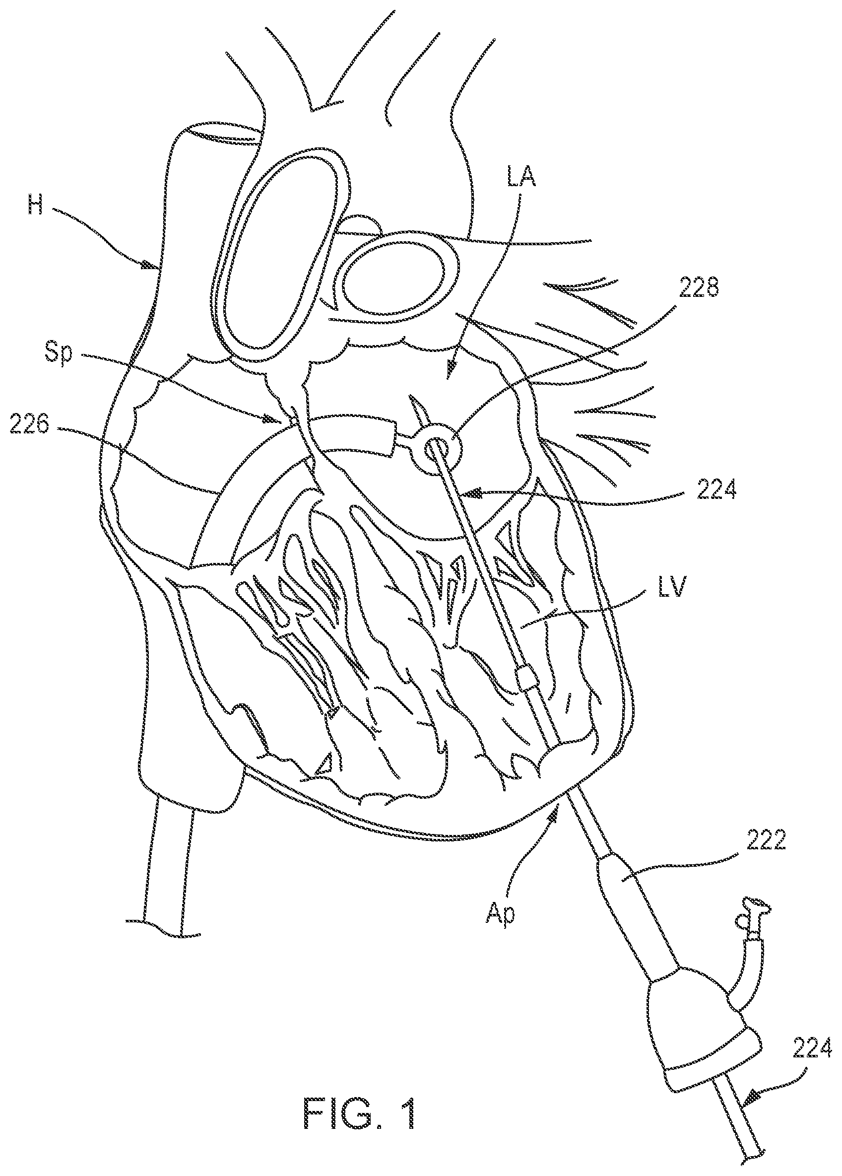
[0066] FIGS. 1-6 illustrate one example method of delivering a prosthetic mitral valve 200 (shown in FIGS. 3-6) to a left atrium LA of a heart H via introduction through a femoral vein. As shown in FIG. 1, a procedural catheter 222 is inserted through an apical puncture (e.g., a 5F apical puncture) in a ventricular wall at the apex Ap of the heart H. A leader tube 224 is inserted through a lumen (not shown) of the procedural catheter 222 and extended through the left ventricle LV, through a mitral valve gap and into the left atrium LA. A delivery sheath 226 is introduced through a femoral vein puncture and extended through the inferior vena cava, into the right atrium, and then through a transseptal puncture of the septum Sp of the heart H, and into the left atrium LA of the heart H. A snare device 228 is movably disposed within the delivery sheath 226 and used to grab or snare a distal end portion of the leader tube 224, as shown in FIG. 1. The snare device 228 can be used to pull the leader tube 224 through the delivery sheath 226 such that the distal end portion of the leader tube 224 extends outside the femoral vein and a proximal end of the leader tube 224 is disposed through the ventricular wall at the apex Ap of the heart H, as shown in FIG. 2. The leader tube 224 allows for back-loading of the prosthetic mitral valve 200 starting in the femoral vein and exiting the heart H at the apex Ap. Although not shown in FIGS. 1 and 2, the procedural catheter 224 is disposed outside the patient's body, the distal end of the leader tube 224 extends outside the femoral vein and outside the patient's body, and the proximal end of the leader tube 224 extends outside the apex Ap and outside the patient's body. Although the above described snare process describes delivering the leader tube 224 to the left atrium of the heart and then snaring the leader tube 224 using the snare device 228, in alternative embodiments, the leader tube 224 can be delivered to the left ventricle LV and the snare device 228 and delivery sheath 226 can be inserted through the mitral annulus and into the left ventricle LV to grab or snare the leader tube 224 as described above.
[0067] After the leader tube 224 has been extended between the apex Ap and the access site to the femoral vein, a valve leader member 234 attached to the prosthetic mitral valve 200 (also referred to as "valve") can be inserted into the leader tube 224 at the femoral end of the leader tube 224 and extended through the leader tube 224 until the valve leader member 234 exits the leader tube at the apex end of the leader tube 224. After the valve leader member 234 is inserted and extended outside the apex Ap, the leader tube 224 can be removed from the patient. For example, the leader tube 224 can be pulled out through the apex puncture site, or through the femoral vein puncture site. Thus, only the valve leader member 234 remains disposed within the body, as shown in FIG. 3.
[0068] The valve leader member 234 can have a tapered distal end 235 to aid in the insertion and maneuvering of the valve leader member 234 through the leader tube 224. The valve leader member 234 is attached at a proximal end portion 237 to a tether line 236 (also referred to herein as "tether"), which is attached to the valve 200. FIG. 26 illustrates an enlarged view of the attachment of the proximal end portion 237 to tether 236. The tether 236 can be formed, for example, as a braided rope or cord as shown, for example, in FIG. 26.
[0069] As shown in FIG. 3, the valve 200 is partially disposed within a lumen of the delivery sheath 226. Although the delivery sheath 226 is used to deliver both the snare device 228 and the valve 200, in other embodiments, a different delivery sheath can be used to deliver the snare device 228 than is used to deliver the valve 200. As shown in FIG. 3, prior to inserting the valve leader member 234 into the leader tube 224, the procedural catheter 222 can be removed. Alternatively, the procedural catheter 222 can be removed after inserting the valve leader member 234.
[0070] Also as shown in FIG. 3, in this embodiment, a portion of the valve 200 is allowed to partially deploy outside a distal end of the delivery sheath 226. The partially deployed portion of the valve 200 can be used as a lead-in to the delivery sheath 226 as the valve 200 is inserted through the femoral vein. For example, the valve 200 can be formed with a shape-memory material (as described in more detail below) and can have a biased undeformed shape and can be manipulated and/or deformed (e.g., compressed and/or expanded) and, when released, return to its original undeformed shape. In some embodiments, the valve 200 can have a biased expanded or undeformed configuration when deployed within a heart, and can be moved to a collapsed or deformed configuration when placed within the lumen of the delivery sheath 226 for delivery through the femoral vein. The valve can be, for example, a valve constructed the same as or similar to, and function in the same or similar manner as, the prosthetic heart valve 500, described in detail below.
[0071] After the valve leader member 234 has been placed in position between the femoral puncture site and the apical puncture site, as described above, the delivery sheath 226 with the valve 200 can be inserted through the femoral puncture site and moved through the femoral vein, through the inferior vena cava, into the right atrium, and then through the septum Sp until a distal end portion of the delivery sheath 226 (with the valve 200) is disposed within the left atrium LA, as shown in FIG. 4. As shown in FIG. 4, the tether 236 extends from the valve 200 through the apical puncture and outside the patient's body. As the delivery sheath 226 is advanced, the tether 236 can optionally be pulled at the apex end to help move the delivery sheath 226, with the valve 200 disposed therein, through the femoral vein, through the septal puncture and into the left atrium LA. The valve 200 can then be fully deployed within the left atrium LA (see, e.g., FIG. 5) by pulling the apex end portion of the tether 236 until the valve 200 is pulled out of the lumen of the delivery sheath 226 and disposed within the left atrium LA. Alternatively, pusher device 238 (see, e.g., FIG. 4) can be inserted within the delivery sheath 226 and used to push the valve 200 outside a distal end of the delivery sheath 226. In yet other embodiments, the pusher device 238 can be used to push the valve 200 while the tether 236 is pulled. In other words, the valve 200 can be deployed by pushing the valve 200 with the pusher device 238, by pulling the valve 200 with the tether 236, or both. The pusher 238 can also be used to aid in positioning the valve 200 in a desired radial orientation within the left atrium LA. For example, the pusher device 238 can define an internal lumen (not shown) that can be placed over an inner frame portion of the valve 200 to hold the inner frame portion in a small diameter, which can help enable the valve 200 to be positioned in a desired radial orientation and be seated within the annulus of the mitral valve. Further examples of such a valve assist device are described below with reference to FIGS. 29-31.
[0072] As shown in FIGS. 5 and 6, as the valve 200 is deployed within the left atrium LA, the valve 200 is allowed to assume its biased expanded or deployed configuration. The delivery sheath 226 can then be removed from the patient and the valve 200 can be positioned and tensioned using the tether 236 to obtain the desired or optimal location in the native mitral annulus and minimize perivalvular leaks. An epicardial pad device 239 can be used to secure the tether 236 and valve 200 in position within the mitral annulus as shown in FIG. 6. For example, an epicardial pad device as described in International Patent Application No. PCT/US14/49218 ("the '218 PCT application"), the disclosure of which is incorporated herein by reference in its entirety, can be used. In some embodiments, an expandable epicardial pad can be used to secure the tether and valve in position. Example embodiments of expandable pads that can be used are described herein with reference to FIGS. 33-47. Such a pad can be smaller in size such that the pad can be delivered to the heart via a small incision and small catheter or delivery sheath. In some embodiments, a positioning device (not shown) can be used to help position the valve 200 and deploy the epicardial pad device. For example, a positioning device as described in the '218 PCT application incorporated by reference above, or devices described in International Patent Application No. PCT/US14/61046, the disclosure of which is incorporated herein by reference in its entirety, can be used. In some embodiments, rather than securing the prosthetic mitral valve with a tether and epicardial pad, the prosthetic mitral valve can be secured with clips or other coupling methods to a portion(s) of the mitral valve apparatus and/or the ventricular wall of the heart. For example, such coupling methods are described in International Patent Application No. PCT/US14/58826 ("the '826 PCT application"), the disclosure of which is incorporated herein by reference in its entirety.
[0073] FIGS. 7-9 illustrate an embodiment of a prosthetic heart valve that can be delivered and deployed within a left atrium of a heart using a transfemoral delivery approach as described above. FIGS. 7-9 are front, bottom, and top views, respectively, of a prosthetic heart valve 500 according to an embodiment. Prosthetic heart valve 500 (also referred to herein as "valve") is designed to replace a damaged or diseased native heart valve such as a mitral valve. Valve 500 includes an outer frame assembly 510 and an inner valve assembly 540 coupled to the outer frame assembly 510.
[0074] As shown, outer frame assembly 510 includes an outer frame 520, covered on all or a portion of its outer face with an outer covering 530, and covered on all or a portion of its inner face by an inner covering 532. Outer frame 520 can provide several functions for prosthetic heart valve 500, including serving as the primary structure, as an anchoring mechanism and/or an attachment point for a separate anchoring mechanism to anchor the valve to the native heart valve apparatus, a support to carry inner valve assembly 540, and/or a seal to inhibit paravalvular leakage between prosthetic heart valve 500 and the native heart valve apparatus.
[0075] Outer frame 520 is configured to be manipulated and/or deformed (e.g., compressed and/or expanded) and, when released, return to its original (undeformed) shape. To achieve this, outer frame 520 can be formed of materials, such as metals or plastics, that have shape memory properties. With regards to metals, Nitinol has been found to be especially useful since it can be processed to be austenitic, martensitic or super elastic. Other shape memory alloys, such as Cu--Zn--Al--Ni alloys, and Cu--Al--Ni alloys, may also be used.
[0076] As best shown in FIG. 7, outer frame assembly 510 has an upper end (e.g., at the atrium portion 516), a lower end (e.g., at the ventricle portion 512), and a medial portion (e.g., at the annulus portion 514) therebetween. The medial portion of the outer frame assembly 510 has a perimeter that is configured (e.g., sized, shaped) to fit into an annulus of a native atrioventricular valve. The upper end of the outer frame assembly 510 has a perimeter that is larger than the perimeter of the medial portion. In some embodiments, the perimeter of the upper end of the outer frame assembly 510 has a perimeter that is substantially larger than the perimeter of the medial portion. As shown best in FIG. 9, the upper end and the medial portion of the outer frame assembly 510 has a D-shaped cross-section. In this manner, the outer frame assembly 510 promotes a suitable fit into the annulus of the native atrioventricular valve.
[0077] Inner valve assembly 540 includes an inner frame 550, an outer covering 560, and leaflets 570. As shown, the inner valve assembly 540 includes an upper portion having a periphery formed with multiple arches. The inner frame 550 includes six axial posts or frame members that support outer covering 560 and leaflets 570. Leaflets 570 are attached along three of the posts, shown as commissure posts 552 (best illustrated in FIG. 8), and outer covering 560 is attached to the other three posts, 554 (best illustrated in FIG. 8), and optionally to commissure posts 552. Each of outer covering 560 and leaflets 570 are formed of approximately rectangular sheets of material, which are joined together at their upper, or atrium end. The lower, ventricle end of outer covering 560 may be joined to inner covering 532 of outer frame assembly 510, and the lower, ventricle end of leaflets 570 may form free edges 575, though coupled to the lower ends of commissure posts 552.
[0078] Although inner valve assembly 540 is shown as having three leaflets, in other embodiments, an inner valve assembly can include any suitable number of leaflets. The leaflets 570 are movable between an open configuration and a closed configuration in which the leaflets 570 coapt, or meet in a sealing abutment.
[0079] Outer covering 530 of the outer frame assembly 510 and inner covering 532 of outer frame assembly 510, outer covering 560 of the inner valve assembly 540 and leaflets 570 of the inner valve assembly 540 may be formed of any suitable material, or combination of materials, such as those discussed above. In this embodiment, the inner covering 532 of the outer frame assembly 510, the outer covering 560 of the inner valve assembly 540, and the leaflets 570 of the inner valve assembly 540 are formed, at least in part, of porcine pericardium. Moreover, in this embodiment, the outer covering 530 of the outer frame assembly 510 is formed, at least in part, of polyester.
[0080] Inner frame 550 is shown in more detail in FIGS. 10-12. Specifically, FIGS. 10-12 show inner frame 550 in an undeformed, initial state (FIG. 10), a side view of the inner frame 550 in a deployed configuration (FIG. 11), and a bottom view of the inner frame 550 in a deployed configuration (FIG. 12), respectively, according to an embodiment.
[0081] In this embodiment, inner frame 550 is formed from a laser-cut tube of Nitinol.RTM.. Inner frame 550 is illustrated in FIG. 10 in an undeformed, initial state, i.e. as laser-cut, but cut and unrolled into a flat sheet for ease of illustration. Inner frame 550 can be divided into four portions, corresponding to functionally different portions of the inner frame 550 in final form: atrial portion 541, body portion 542, strut portion 543, and tether clamp or connecting portion 544. Strut portion 543 includes six struts, such as strut 543A, which connect body portion 542 to tether clamp portion 544.
[0082] Connecting portion 544 includes longitudinal extensions of the struts, connected circumferentially by pairs of opposed, slightly V-shaped connecting members (or "micro-Vs"). Connecting portion 544 is configured to be radially collapsed by application of a compressive force, which causes the micro-Vs to become more deeply V-shaped, with the vertices moving closer together longitudinally and the open ends of the V shapes moving closer together circumferentially. Thus, connecting portion 544 can be configured to compressively clamp or grip one end of a tether, either connecting directly onto a tether line (e.g. braided filament line) or onto an intermediate structure, such as a polymer or metal piece that is in turn firmly fixed to the tether line.
[0083] In contrast to connecting portion 544, atrial portion 541 and body portion 542 are configured to be expanded radially. Strut portion 543 forms a longitudinal connection, and radial transition, between the expanded body portion and the compressed connecting portion 544.
[0084] Body portion 542 includes six longitudinal posts, such as post 542A. The posts can be used to attach leaflets 570 to inner frame 540, and/or can be used to attach inner assembly 540 to outer assembly 510, such as by connecting inner frame 550 to outer frame 520. In the illustrated embodiment, the posts include openings through which connecting members (such as suture filaments and/or wires) can be passed to couple the posts to other structures.
[0085] Inner frame 550 is shown in a fully deformed, i.e. the final, deployed configuration, in side view and bottom view in FIGS. 11 and 12, respectively.
[0086] Outer frame 520 of valve 500 is shown in more detail in FIGS. 13-15. In this embodiment, outer frame 520 is also formed from a laser-cut tube of Nitinol.RTM.. Outer frame 520 is illustrated in FIG. 13 in an undeformed, initial state, i.e. as laser-cut, but cut and unrolled into a flat sheet for ease of illustration. Outer frame 520 can be divided into a coupling portion 571, a body portion 572, and a cuff portion 573, as shown in FIG. 13. Coupling portion 571 includes multiple openings or apertures, such as 571A, by which outer frame 520 can be coupled to inner frame 550, as discussed in more detail below.
[0087] Outer frame 520 is shown in a fully deformed, i.e. the final, deployed configuration, in side view and top view in FIGS. 14 and 15, respectively. As best seen in FIG. 15, the lower end of coupling portion 571 forms a roughly circular opening (identified by "0" in FIG. 15). The diameter of this opening preferably corresponds approximately to the diameter of body portion 542 of inner frame 550, to facilitate coupling of the two components of valve 500.
[0088] Outer frame 520 and inner frame 550 are shown coupled together in FIGS. 16-18, in front, side, and top views, respectively. The two frames collectively form a structural support for a prosthetic valve such as valve 500. The frames support the valve leaflet structure (e.g., leaflets 570) in the desired relationship to the native valve annulus, support the coverings (e.g., outer covering 530, inner covering 532, outer covering 560) for the two frames to provide a barrier to blood leakage between the atrium and ventricle, and couple to the tether (e.g., tether assembly 590) (by the inner frame 550) to aid in holding the prosthetic valve in place in the native valve annulus by the tether connection to the ventricle wall. The outer frame 520 and the inner frame 550 are connected at six coupling points (representative points are identified as "C"). In this embodiment, the coupling points are implemented with a mechanical fastener, such as a short length of wire, passed through an aperture (such as aperture 571A) in coupling portion 571 of outer frame 520 and corresponding openings in longitudinal posts (such as post 542A) in body portion 542 of inner frame 550. Inner frame 550 is thus disposed within the outer frame 520 and securely coupled to it.
[0089] FIGS. 19-25 illustrate a method of reconfiguring a prosthetic heart valve 300 (e.g., prosthetic mitral valve) prior to inserting the prosthetic heart valve 300 into a delivery sheath 326 (see, e.g., FIGS. 21-25) for delivery into the heart via the femoral vein. The prosthetic heart valve 300 (also referred to herein as "valve") can be constructed the same as or similar to, and function the same as or similar to the valve 500 described above. Thus, some details regarding the valve 300 are not described below. It should be understood that for features and functions not specifically discussed, those features and functions can be the same as or similar to the valve 500.
[0090] As shown in FIG. 19, the valve 300 has an outer frame 320 and an inner frame 350. As discussed above for valves 200 and 500, the outer frame 320 and the inner frame 350 of valve 300 can each be formed with a shape-memory material and have a biased expanded or deployed configuration. The outer frame 320 and the inner frame 350 can be moved to a collapsed or undeployed configuration for delivery of the valve 300 to the heart. In this example method of preparing the valve 300 for delivery to the heart, the outer frame 320 of the valve 300 is first disposed in a prolapsed or inverted configuration as shown in FIG. 20. Specifically, the elastic or superelastic structure of outer frame 320 of valve 300 allows the outer frame 320 to be disposed in the prolapsed or inverted configuration prior to the valve 300 being inserted into the lumen of the delivery sheath 326. As shown in FIG. 20, to dispose the outer frame 320 in the inverted configuration, the outer frame 320 is folded or inverted distally such that the outer frame 320 is pointed away from the inner frame 350. In this inverted configuration, the overall outer perimeter or outer diameter of the valve 300 is reduced and the overall length is increased. For example, the diameter D1 shown in FIG. 19 is greater than the diameter D2 shown in FIG. 20, and the length L1 in FIG. 16 is less than the length L2 in FIG. 20. With the outer frame 320 in the inverted configuration, the valve 300 can be placed within a lumen of a delivery sheath 326 as shown in FIG. 21 for delivery of the valve 300 to the left atrium of the heart. By disposing the outer frame 320 in the inverted configuration, the valve 300 can be collapsed into a smaller overall diameter, i.e. placed in a smaller diameter delivery sheath, than would be possible if the valve 300 in the configuration shown in FIG. 19 were collapsed radially. This is because in the configuration shown in FIG. 19, the two frames are concentric, and thus the outer frame 320 must be collapsed around the inner frame 350, whereas in the configuration shown in FIG. 20, the two frames are coaxial but not concentric, such that the outer frame 320 can be collapsed without needing to accommodate the inner frame 350 inside it.
[0091] The procedure to deliver the valve 300 to the heart can be the same as or similar to the procedure described with reference to FIGS. 1-6. In this embodiment, the valve 300 is not partially deployed outside of the lumen of the delivery sheath 326 prior to being inserted into a femoral puncture, through the femoral vein, through the inferior vena cava, into the right atrium, through the septum Sp and into the left atrium LA of the heart. With the distal end portion of the delivery sheath 326 disposed within the left atrium of the heart, the valve 300 can be deployed outside of the delivery sheath 326. For example, although not shown, a tether such as tether 236 described above for valve 200 can be attached to the valve 300 and used to pull the valve 300 out of the lumen of the delivery sheath 326. Alternatively, or in addition to, a pusher device (not shown) can be used to deploy the valve 300. Thus, as described above for valve 200, the valve 300 can be deployed by pushing with the pusher device, pulling with the tether, or both.
[0092] As the valve 300 exits the lumen of the delivery sheath 326, the outer frame assembly 310 exits first in its inverted configuration as shown in the progression of FIGS. 22-24. After the outer frame assembly 310 is fully outside of the lumen of the delivery sheath 326, the outer frame 320 can revert to its expanded or deployed configuration as shown in FIG. 25. In some embodiments, the pusher device and/or the tether can be used to aid in the reversion of the outer frame assembly 310. The valve 300 can continue to be deployed until the inner frame 350 is fully deployed with the left atrium and the valve 300 is in the expanded or deployed configuration (as shown in FIG. 19).
[0093] FIGS. 27 and 28 illustrate an optional balloon dilator device that can be used during a procedure for transfemoral delivery of a prosthetic heart valve to the heart. FIG. 27 illustrates a valve 400 disposed within a lumen of a delivery sheath 426. The valve 400 can be constructed the same as or similar to, and function the same as or similar to, the valves 200, 500 and 300 described above. For example, the valve 400 can include an outer frame 420 and an inner frame 450 as described above for previous embodiments. A tether 436 can be coupled to the valve 400 and a valve leader member 434 (see FIG. 28) can be coupled to the tether 436.
[0094] In this embodiment, to deliver the valve 400, a leader tube (not shown) can be inserted through an apical puncture and extended through the heart and out through a femoral vein access site. A valve leader member 434 coupled to a tether 436 can be inserted through the femoral end of the leader tube and extended out the apical end of the leader tube, as described above with respect to FIGS. 1-6. The valve 400 can be loaded into the distal end of a lumen of a delivery sheath 426 either before or after the tether 436 and valve leader member 434 are looped through the patient. A balloon dilator device 445 can then be advanced along the valve leader member 434 from the apical end, through the heart, through the femoral vein and out the femoral access site.
[0095] The balloon dilator device 445 includes a balloon member 446 that can be disposed at least partially within the distal end portion of the lumen of the delivery device 426, and distal of the valve 400, as shown in FIG. 27. The balloon dilator device 445 also includes an elongate member 447 coupled to the balloon member 446 and that defines an inflation lumen in fluid communication with an interior of the balloon member 446. The elongate member 447 can be coupled to a source of an inflation medium (not shown) configured to supply the inflation medium to the balloon member 446. With the balloon dilator device 445 coupled to the delivery sheath 426 as shown in FIG. 27, the balloon member 446 can be inflated. The delivery sheath 426 can then be inserted through the femoral access site and advanced through the femoral vein, through the inferior vena cava, into the right atrium, through the septum Sp and into the left atrium LA as shown in FIG. 28. The balloon member 446 provides a smooth surface to aid in maneuvering the delivery sheath 426 through the femoral vein and the septum and into the heart. With the distal end portion of the delivery sheath 426 disposed within the left atrium LA, the balloon member 446 can be deflated and removed through the apical access site. The valve 400 can then be deployed and positioned within the mitral annulus as described above for FIGS. 1-6. For example, a pusher device 438 (see FIG. 27) can be used to push the valve 400 out of the lumen of the delivery sheath 426 and/or the tether 436 coupled to the valve 400 can be pulled.
[0096] FIGS. 29 and 30 illustrate an optional wire assist structure that can be used during a procedure to deliver a prosthetic heart valve transfemorally as described above for previous embodiments. A wire assist structure 649 can be releasably coupled to a valve 600 as shown in FIG. 29. The valve 600 can be constructed the same as or similar to, and function the same as or similar to, the valves described above for previous embodiments. For example, the valve 600 can include an outer frame 620 and an inner frame 650. The wire assist structure 649 can be releasably coupled to the inner frame 650 as best shown in FIG. 30. For example, releasable connectors (not shown) can be used to couple the wire assist structure 649 to the inner frame 650.
[0097] In use, the wire assist structure 649 can be movably disposed within a delivery sheath 626 used to deliver the valve 600 to the heart. The wire assist structure 649 can hold the inner frame 650 and allow for positioning control of the valve 600 (i.e., clocking and advancement) while the outer frame 650 of the valve 600 is fully expanded, which allows the valve 600 to be functioning during the positioning phase. When the valve 600 is in the desired final position, the wire assist structure 649 can be released from the inner frame 650 and removed with the delivery sheath 626.
[0098] FIG. 31 illustrates another optional assist member that can be used during a procedure to deliver a prosthetic heart valve transfemorally. An assist member 748 can be in the form of a tubular member defining a lumen with a diameter sized to receive at least a portion of the inner frame 750 of a valve 700. The valve 700 can be constructed the same as or similar to, and function the same as or similar to, the valves described above for previous embodiments. For example, the valve 700 can include an outer frame (not shown) and the inner frame 750 as described above for previous embodiments.
[0099] In use, the assist member 748 can be movably disposed within a delivery sheath (not shown) used to deliver the valve 700 and be disposed over at least a portion of the inner valve assembly 740. As with the wire assist structure 649, the assist member 748 can hold the inner frame 750 in a small compact configuration and allow for positioning control of the valve 700 (i.e., clocking and advancement) while the outer frame of the valve 700 is being expanded. This can in some cases allow the valve 700 to be functioning (or at least partially functioning) during the positioning phase of the valve 700. With the inner frame 750 held in a compact or small diameter form factor, the valve 700 can be more easily positioned to help seal the annulus with the outer frame (not shown) of the valve 700. When the valve 700 is in the desired final position, the assist member 748 can be removed.
[0100] FIG. 32 is a flowchart illustrating a method of deploying a prosthetic mitral valve to a heart using a transfemoral delivery approach. The method includes at 880, inserting a leader tube through an access site on the skin of the patient, through an access puncture site on the apex of the heart, and positioning a distal end portion of the leader tube in the left atrium of the heart. At 881, inserting a delivery sheath with a snare device coupled thereto through an access site into the femoral vein and into the left atrium of the heart. At 882, the leader tube is captured with the snare device, and pulled through the femoral vein such that the leader tube extends between the apex of the heart and the entry to the femoral vein. At 883, an outer frame of a prosthetic mitral valve is disposed in an inverted configuration when the mitral valve is in a biased expanded configuration. For example, the prosthetic mitral valve can be formed with a shape-memory material and have a biased expanded configuration.
[0101] At 884, after inverting the outer frame, the prosthetic mitral valve is inserted into a lumen of a delivery sheath such that the prosthetic mitral valve is moved to a collapsed configuration. The delivery sheath can be the same delivery sheath as used with the snare device or a different delivery sheath. At 885, a valve leader member is inserted to the leader tube at the femoral end of the leader tube, and moved through the leader tube until the valve leader member exits the leader tube outside of the apex of the heart. A proximal end of the valve leader member is coupled to a tether line that in turn is coupled to the prosthetic mitral valve and disposed within the delivery sheath. At 886, the delivery sheath is inserted into the femoral vein and moved through the femoral vein and through a septum of a heart until a distal end portion of the delivery sheath is disposed in the left atrium of the heart. At 887, the prosthetic mitral valve is moved distally out of the delivery sheath such that the inverted outer frame of the prosthetic mitral valve reverts, and the prosthetic mitral valve assumes its biased expanded configuration. At 888, the prosthetic mitral valve is positioned within a mitral annulus of the heart and optionally an epicardial pad device can be secured to the apex of the heart to maintain the prosthetic mitral valve in the desired position (e.g., orientation) within the mitral annulus. In some embodiments, rather than securing the prosthetic mitral valve with a tether and epicardial pad, the prosthetic mitral valve can be secured with clips or other coupling methods to a portion(s) of the ventricular wall of the heart.
[0102] FIGS. 33-37 illustrate an embodiment of an expandable epicardial pad device that can be used to secure a tether attached to a prosthetic mitral valve to the heart, for example, at the apex of the heart. An epicardial pad device 939 (also referred to herein as "epicardial pad" or "pad") can be used, for example, during a procedure to deliver a prosthetic heart valve as described herein. The epicardial pad 939 can be formed with a small profile such that the epicardial pad 939 can be delivered to the exterior of the heart via a small incision and a small diameter delivery catheter or sheath 963 (see FIGS. 33 and 34). In some embodiments, the delivery sheath 963 can have a diameter, for example, in the range of 3-5 mm. An inner delivery sheath 964 can be movably disposed within a lumen of the delivery sheath 963 and used to hold the tether 936 while the epicardial pad 939 is being deployed as described in more detail below.
[0103] As shown in FIGS. 33 and 34 the epicardial pad 939 includes a frame member 961 and a fabric cover 962. The frame member 961 can be formed with, for example a shape-memory material such as Nitinol.RTM. such that the epicardial pad 939 can have a biased expanded configuration as shown in FIGS. 34 and 36, and can be moved to a collapsed configuration as shown in FIG. 33. For example, as shown in FIG. 33 the epicardial pad 939 can be placed within a lumen of the delivery sheath 963 to move the epicardial pad 939 to the collapsed configuration. The fabric cover 962 can be formed with various suitable material(s) such as, for example, polyester, polyethylene or ePTFE.
[0104] In use, after a prosthetic mitral valve has been deployed within the heart H (e.g., via a transfemoral delivery approach as described herein or a transatrial delivery approach), the tether 936 attached to the prosthetic valve (not shown) can extend outside the apex of the heart. The epicardial pad 939 can be used to secure the tether 936 and prosthetic valve in a desired position. With the tether 936 extending outside of the heart, the tether 936 can be threaded through a center opening of the epicardial pad 939 and through a lumen of the inner delivery sheath 964, as shown in FIGS. 33 and 34. The outer delivery sheath 963 can be placed over the inner delivery sheath 964 and the epicardial pad 939 to collapse the epicardial pad 939 as shown in FIG. 33. Although not shown, the epicardial pad 936 can be entirely disposed within the lumen of the outer delivery sheath 963 during delivery. As described above, the outer delivery sheath 963 can have a relatively small outer diameter such that it can be inserted through a small incision in the skin of the patient. When the distal end of the delivery sheath 963 is at a desired location near the apex of the heart, the epicardial pad 939 can be moved outside of the delivery sheath 963 such that the epicardial pad 939 can assume its biased expanded configuration as shown in FIGS. 34 and 36. For example, to move the epicardial pad 939 outside of the lumen of the delivery sheath 963, the delivery sheath 963 can be moved proximally, such that the deliver sheath 963 is removed from epicardial pad 939. Alternatively, the epicardial pad 939 can be moved distally outside of the lumen of the delivery sheath 963. For example, a push rod (not shown) can be used, or the inner delivery sheath 964 in which the tether 936 is disposed can be used to move or push the epicardial pad 939 out of the delivery sheath 963.
[0105] Prior to moving the expanded epicardial pad 939 into position on the apex of the heart, conventional purse-string sutures 965 at the incision through which the tether 936 extends out of the heart at the apex of the heart can be closed. Although purse-string sutures 965 are illustrated in this embodiment, the epicardial pad 939 can alternatively be implemented without the use of such purse-string sutures 965. The epicardial pad 939, in the expanded configuration, can then be positioned on the apex of the heart. In this embodiment, the epicardial pad 939 includes an integral locking mechanism that includes barbs 967 as shown in FIGS. 37-39. The locking mechanism or barbs 967 can be formed integrally with the frame member 961. As shown in FIGS. 33 and 34, the tether 936 can be inserted through a lumen of the inner delivery sheath 964 such that the delivery sheath 964 can prevent the barbs 967 from contacting the tether 936. For example, the tether 936 can be threaded into the inner delivery sheath 964 prior to the inner delivery sheath 964 and tether 936 being inserted through the center opening of the epicardial pad 939. Thus, the inner delivery sheath 964 can protect the tether 936 from the barbs 967 during deployment of the epicardial pad 939. When the epicardial pad 939 is deployed at the desired position on the apex region of the heart, the inner delivery sheath 964 can be removed uncovering the tether 936 and allowing the barbs 967 to engage or pierce the tether 936 as shown in FIGS. 38 and 39. The barbs 967 can hold or lock the tether 936 and epicardial pad 939 in the desired position. The barbs 967 can be oriented at various different angles relative to a longitudinal axis of the epicardial pad 939, such as, for example, between 45-120 degrees.
[0106] In alternative embodiments, other methods of securing the epicardial pad 939 to the heart can be used. For example, in an embodiment in which the epicardial pad 939 does not include an integrated locking mechanism as described above, the distal end portion of the tether 936 can be tied or another securing device such as a clip or locking pin can be used.
[0107] FIGS. 40-42 illustrate another embodiment of an expandable epicardial pad device that can be used to secure a tether attached to a prosthetic mitral valve to the heart, for example, at the apex of the heart. An epicardial pad device 1039 (also referred to herein as "epicardial pad" or "pad") can be used, for example, during a procedure to deliver a prosthetic heart valve as described herein. The epicardial pad 1039 can be formed with a small profile such that the epicardial pad 1039 can be delivered to the exterior of the heart via a small incision and a small diameter delivery catheter or sheath (not shown) as described above for epicardial pad 939.
[0108] As shown in FIGS. 40-42, the epicardial pad 1039 includes a frame member 1061 and a fabric cover 1062. In this embodiment, the frame member 1061 includes a first frame portion 1068 and a second frame portion 1069. As with the previous embodiment, the frame member 1061 can be formed with, for example a shape-memory material such as Nitinol.RTM., such that the epicardial pad 1039 can have a biased expanded configuration as shown in FIGS. 41 and 42, and can be moved to a collapsed configuration as shown in FIG. 40. For example, although not shown for this embodiment, the epicardial pad 1039 can be placed within a lumen of a delivery sheath to collapse or move the epicardial pad 1039 to the collapsed configuration. In the expanded configuration, the second frame portion 1069 expands within an interior region defined by the first frame portion 1068 as best shown in FIG. 41. In other words, the second frame portion 1069 and the first frame portion 1068 form a double-layer flower-like shape. The fabric cover 1062 can be formed with, for example, various suitable material(s) such as, for example, polyester, polyethylene or ePTFE, as described above for fabric cover 962.
[0109] In use, after a prosthetic mitral valve has been deployed within the heart H (FIG. 42), for example, via a transfemoral delivery approach as described herein, the tether 1036 attached to the prosthetic valve (not shown) can extend outside the apex of the heart. The epicardial pad 1039 can be used to secure the tether 1036 and prosthetic valve in a desired position. With the tether 1036 extending outside of the heart, the tether 1036 can be threaded through a lumen of an inner delivery sheath (not shown), such as inner delivery sheath 964 described above, and through a center opening of the epicardial pad 1039. An outer delivery sheath (not shown) can be placed over the inner delivery sheath to collapse the epicardial pad 1039. As described above, the outer delivery sheath can have a relatively small outer diameter such that it can be inserted through a small incision in the skin of the patient. When the distal end of the delivery sheath is at a desired location near the apex of the heart, the epicardial pad 1039 can be moved outside of the outer delivery sheath such that the epicardial pad 1039 can assume its biased expanded configuration as shown in FIGS. 41 and 42 in a similar manner as described above for epicardial pad 939.
[0110] Prior to moving the expanded epicardial pad 1039 into position on the apex of the heart, conventional purse-string sutures 1065 at the incision through which the tether 1036 extends out of the heart at the apex of the heart can be closed. As with the previous embodiment, although purse-string sutures 1065 are illustrated in this embodiment, the epicardial pad 1039 can alternatively be implemented without such purse-string sutures 1065. The epicardial pad 1039, in the expanded configuration, can then be positioned on the apex of the heart. The epicardial pad 1039 can include an integral locking mechanism, similar to or the same as locking mechanism (e.g., barbs) described above to secure or lock the tether 1036 and epicardial pad 1039 in position on the heart. In alternative embodiments, other methods of securing the epicardial pad 1039 to the heart can be used. For example, as described above, the distal end portion of the tether 1036 can be tied or another securing device such as a clip or locking pin can be used.
[0111] FIGS. 43 and 44 illustrate an expandable epicardial pad device 1139 according to another embodiment. The epicardial pad device 1139 can be used in the same or similar manner as described for previous embodiments to secure a tether attached to a prosthetic mitral valve to the heart, for example, at the apex of the heart. The epicardial pad device 1139 (also referred to herein as "epicardial pad" or "pad") can be used, for example, during a procedure to deliver a prosthetic heart valve as described herein. In this embodiment, the epicardial pad device 1139 includes a balloon member 1155. The balloon member 1155 can be small in size such that the balloon member 1155 can be delivered to the exterior of the heart via a small incision and a small diameter delivery catheter or sheath (not shown) as described above for previous embodiments.
[0112] The balloon member 1155 can define an inner lumen through which the tether 1136 can be inserted. The epicardial pad 1139 can also include an inflation lumen through which an inflation medium can be communicated to and from the balloon member 1155. For example, the inflation lumen (not shown) can be defined by the balloon member 1155 or by a separate inflation line (not shown) in fluid communication with an interior of the balloon member 1155.
[0113] In use, after a prosthetic mitral valve has been deployed within the heart H (FIG. 43), as described herein, the tether 1136 attached the prosthetic valve (not shown) can extend outside the apex of the heart. With the tether 1136 extending outside of the heart, the tether 1136 can be threaded or inserted through the lumen of the balloon member 1155 as described above. The balloon member 1155 can be inflated or deflated when the tether 1136 is inserted into the balloon lumen. The balloon member 1155 can be collapsed or deflated (not shown) and then placed within a lumen of a delivery sheath (not shown). The delivery sheath can be inserted through a small incision in the skin of the patient and a distal end of the delivery sheath disposed at a desired location near the apex of the heart. The epicardial pad 1139 (i.e., balloon member 1155) can be moved outside of the delivery sheath and then can be inflated as shown in FIG. 43.
[0114] Purse-string sutures 1165 at the incision through which the tether 1136 extends out of the heart at the apex of the heart can be closed prior to positioning the epicardial pad 1139 on the apex. As with previous embodiments, although purse-string sutures 1165 are illustrated in this embodiment, the epicardial pad 1139 can alternatively be implemented without such purse-string sutures 1165. Prior to positioning the balloon member 1155 on the apex of the heart, the balloon member 1155 can be partially deflated or fully deflated. The balloon member 1155 is then moved distally into contact with the heart where it can collapse inwardly upon itself to form a cup shape as the balloon member 1155 is pushed against the heart, as shown in FIG. 44. The epicardial pad 1139 and tether 1136 can be secured in the desired position with, for example, clip(s) or a locking pin(s) or by tying the tether 1136. In some embodiments, the balloon member 1155 is secured by adhesively coupling the balloon member 1155 to the tether 1136 such that the balloon member 1155 is prevented from moving relative to the tether 1136. In some embodiments, the balloon member 1155 can be adhesively coupled to the tether 1136 and also adhesively coupled to the heart. In some embodiments, the balloon member 1155 is fully deflated and can be filled with an adhesive or a cement material to add strength and rigidity to the balloon member 1155.
[0115] FIGS. 45-47 illustrate yet another embodiment of an epicardial pad device that can be used to secure a tether attached to a prosthetic mitral valve to the heart, for example, at the apex of the heart. The epicardial pad device 1239 (also referred to herein as "epicardial pad" or "pad") can be used, for example, during a procedure to deliver a prosthetic heart valve as described herein. In this embodiment, the epicardial pad device 1239 includes multiple stackable pad members 1273 that can be sized such that each stackable pad member 1273 can be delivered separately to the exterior of the heart via a small incision and a small diameter delivery catheter or sheath (not shown). When all of the stackable pad members 1273 are implanted and attached to the heart, the stackable pad members 1273 can define a total surface area of, for example, 2 cm. The stackable pad members 1273 can be formed with, for example, suitable polymer or metal materials such as, for example, PEEK plastic, or stainless steel such as, for example, MP35N stainless steel.
[0116] In use, after a prosthetic mitral valve has been deployed within the heart H, for example, via a transfemoral delivery approach as described herein, the tether 1236 attached to the prosthetic valve (not shown) can extend outside the apex of the heart. With the tether 1236 extending outside of the heart, a first stackable pad member 1273 can be slid onto the tether 1236. For example, the stacking members 1273 can define a through-hole in which the tether 1236 can be received. The first stackable pad member 1273 can be slid or moved distally along the tether 1236 until it contacts the surface of the heart H as shown in FIG. 45. A second stackable pad member 1273 can then be slid distally along the tether 1236 until it contacts the first stackable pad member 1273 and then a third stackable pad member 1273 can be slid distally along the tether 1236 until it contacts the second stackable pad member 1273 as shown in FIG. 46. Each stackable pad member 1273 can be oriented at a different angle relative to the tether 1236 as shown in FIG. 47. Using three separate stackable pad members 1273 in this manner can distribute the forces against the surface of the heart more evenly than a single stackable pad member 1273. After the three stackable pad members 1273 have been positioned against the heart, a locking pin 1274 can be inserted laterally through the tether 1236 to secure the stackable pad members 1273 against the surface of the heart. Although three stackable pad members 1273 are shown with respect to epicardial pad device 1239, a different number of stackable pads 1273 can alternatively be used, such as, for example, 2, 4, 5, 6, etc. In some embodiments, it may be desirable to insert a locking pin after each stackable pad member 1273 has been positioned.
[0117] In some embodiments, prior to deployment of an epicardial pad device to secure a tether and a prosthetic valve in a desired position, as discussed above, for example, with respect to FIGS. 33-37, an expandable tissue dilator device can be used to dilate tissue or otherwise create space suitable for delivery and/or deployment of the epicardial pad device. FIGS. 48-50 illustrate an embodiment of an expandable tissue dilator device 1376 (also referred to herein as "tissue dilator") that can be used to dilate tissue or otherwise create space suitable for delivery and/or deployment of an epicardial pad device 1339 (see FIGS. 51 and 52). The epicardial pad device 1339 can be the same as or similar to any epicardial pad device described herein or in International PCT Application No. PCT/US2014/0049218 (the '218 PCT Application), and can be used in the same or similar manner as described for previous embodiments herein or in the '218 PCT Application to secure a tether attached to a prosthetic mitral valve to the heart, for example, at the apex of the heart.
[0118] The tissue dilator 1376 can be used, for example, during a procedure to deliver a prosthetic heart valve transfemorally as described herein or in any other suitable delivery method (e.g., transapical, transatrial, transjugular). In this embodiment the tissue dilator 1376 can include an expandable member 1377 coupled to a distal end of an elongate member (not shown). The expandable member 1377 can be moved between a collapsed configuration for delivery of the expandable member 1377 and an expanded configuration, in which the size (e.g., diameter) of the expandable member 1377 is greater than when in the collapsed configuration. When in the collapsed configuration, the expandable member 1377 can be introduced through a lumen defined by a small profile delivery sheath 1363 and to a desired location within a patient's body (e.g., near a patient's heart H). The expandable member 1377 can be moved to the expanded configuration when at the desired location to dilate surrounding tissue as described in more detail below. In some embodiments, the expandable member 1377 can be a balloon that can be expanded (e.g., inflated) with an inflation medium. For example, the elongate member (not shown) can define a lumen that can communicate an inflation medium to and from the expandable member 1377. The tissue dilator 1376 can be delivered to the exterior of the heart via a small incision I, in which the delivery catheter or sheath 1363 (see FIG. 49) can be inserted. In some embodiments, the delivery sheath 1363 can have a diameter, for example, in the range of 3-5 mm.
[0119] In use, after a prosthetic mitral valve has been deployed within the heart H via a transfemoral approach (as described herein), a transapical approach, or other suitable delivery approach, the tether 1336 attached to the prosthetic valve (not shown) can extend outside the apex of the heart H and outside the patient's body via a small incision I (see, e.g., FIG. 48). A proximal end of the tether 1336 can be threaded into and through a distal end of a lumen of the delivery sheath 1363. In this manner, the tether 1336 can provide a guide or otherwise assist in the insertion and movement of the delivery sheath 1363 through the incision I in the skin of the patient. A distal end 1378 of the delivery sheath 1363 can be moved along the tether 1336 and disposed at a desired location near the apex of the heart H (see FIG. 49). The expandable member 1377 of the tissue dilator 1376, when in its collapsed or deflated configuration, can be delivered to the apex region of the heart via the delivery sheath 1363. More specifically, the tissue dilator 1376, with the expandable member 1377 in its collapsed or deflated configuration, can be inserted through the proximal end of the lumen of the delivery sheath 1363, and moved distally towards the distal end of the delivery sheath 1363. In some embodiments, the tissue dilator 1376 can be inserted into the delivery sheath 1363 prior to the delivery sheath 1363 being inserted into the body of the patient. The expandable member 1377 of the tissue dilator 1376 can then be extended outside the distal end of the lumen of the delivery sheath 1363 (see FIG. 49), and moved to its expanded configuration (e.g., inflated), as shown in FIG. 50. For example, to move the expandable member 1377 of the tissue dilator 1376 outside of the lumen of the delivery sheath 1363, the delivery sheath 1363 can be moved proximally, such that the deliver sheath 1363 is removed from the expandable member 1377 of the tissue dilator 1376. Alternatively or additionally, the tissue dilator 1376 can be moved distally such that the expandable member 1377 is moved outside of the lumen of the delivery sheath 1363.
[0120] With the expandable member 1377 disposed outside the heart of the patient (e.g., between the patient's ribs and the heart) the expandable member 1377 can be moved to its expanded configuration such that tissue near the expandable member 1377 is dilated by the pressure exerted by the expandable member 1377 on the surrounding tissue. For example, the elongate member of the tissue dilator 1376 can be fluidically coupled directly, or via a fluid line (not shown), to a source of an inflation medium suitable to expand (e.g., inflate) the expandable member 1377. When the expandable member 1377 is disposed at the desired location in the patient near the apex of the heart, the expandable member 1377 can be expanded. In this manner, the tissue dilator 1376 can be used to dilate tissue or otherwise create space suitable for delivery and/or deployment (e.g., expansion and securement to the heart H) of the epicardial pad device 1339, as described in more detail below.
[0121] After inflation of the expandable member 1377 of the tissue dilator 1376, and the dilation of the surrounding tissue, the expandable member 1377 of the tissue dilator 1376 can be deflated or collapsed and withdrawn proximally (not shown) through the lumen of the delivery sheath 1363 and outside of the patient. In some embodiments, the delivery sheath 1363 can be removed from the patient's body at the same time or after the tissue dilator 1376 is removed. The tether 1336 extending outside of the patient can be threaded through a center opening of the epicardial pad 1339 and through a lumen of an inner delivery sheath (not shown). The epicardial pad 1339 can be used to secure the tether 1336 and the prosthetic valve (not shown) in a desired position. The delivery sheath 1363 can be placed over the inner delivery sheath and the epicardial pad 1339 to collapse the epicardial pad 1339 in a similar manner as described above for previous embodiments.
[0122] The delivery sheath 1363 can then be re-inserted through the small incision I in the skin of the patient and a distal end of the delivery sheath 1363 disposed near the apex of the heart. When the distal end of the delivery sheath 1363 is at the desired location near the apex of the heart, the epicardial pad 1339 can be moved outside the distal end of the delivery sheath 1363 such that the epicardial pad 1339 can assume a biased expanded configuration (see FIG. 51), similar to, for example, the epicardial pad 936 described above, or can be moved to an expanded configuration as described above for epicardial pad 1139. For example, to move the epicardial pad 1339 outside of the lumen of the delivery sheath 1363, the delivery sheath 1363 can be moved proximally, such that the delivery sheath 1363 is removed from epicardial pad 1339. Alternatively, the epicardial pad 1339 can be moved distally outside of the lumen of the delivery sheath 1363. For example, a push rod (not shown) can be used, or the inner delivery sheath (not shown) in which the tether 1336 is disposed can be used to move or push the epicardial pad 1339 out of the delivery sheath 1363. Upon delivery and deployment of the epicardial pad 1339 about the heart H, the delivery sheath 1363 can be removed from the patient and the incision I can be closed with sutures S (see FIG. 52).
[0123] In other alternative embodiments, an expandable tissue dilator device can define an inner lumen through which the tether can be inserted. The tissue dilator can also include an inflation lumen through which an inflation medium can be communicated to and from the expandable member of the tissue dilator, as previously described. For example, the inflation lumen can be defined by the tissue dilator or by a separate inflation line that can be disposed within a lumen of the tissue dilator (e.g., a lumen defined by the elongate member of the tissue dilator). In such embodiments, in use, after a prosthetic mitral valve has been deployed within the heart, the tether attached to the prosthetic valve can extend outside the apex of the heart, as described with respect to previous embodiments. With the tether extending outside of the heart, the tether can be threaded or inserted through the lumen of the tissue dilator. As described with respect to previous embodiments, the expandable member of the tissue dilator can be collapsed or deflated and placed within the lumen of the delivery sheath. The delivery sheath can be inserted through a small incision in the skin of the patient and a distal end of the delivery sheath disposed at a desired location near the apex of the heart. The expandable member of the tissue dilator can be moved outside a distal end of the delivery sheath and expanded at or near the heart (e.g., the apex region) as shown and described with respect to the tissue dilator 1376.
[0124] After expanding the expandable member of the tissue dilator, and in turn creating space suitable for delivery and/or deployment of an epicardial pad device, the tissue dilator can be collapsed or deflated and withdrawn proximally about the tether and through the lumen of the delivery sheath and outside of the patient. The delivery sheath can be withdrawn from the patient's body through the small incision I. Upon removal of the tissue dilator and the delivery sheath from the tether, the proximal end of the tether can be threaded through a center opening of the epicardial pad and an inner sheath, and the epicardial pad can be delivered to and deployed at the heart using the delivery sheath, as described in previous embodiments.
[0125] In alternative embodiments, the tissue dilator can be delivered through a lumen of a delivery sheath separate from the delivery sheath through which the epicardial pad is delivered. Said another way, the tissue dilator can be delivered through a first delivery sheath and the epicardial pad can be delivered through a second delivery sheath.
[0126] In yet other alternative embodiments, a delivery sheath can include multiple lumens (e.g., two lumens). In such embodiments, the tether can be routed or threaded through a first lumen of the delivery sheath, and the tissue dilator can be routed and delivered through the second lumen of the delivery sheath. In such an embodiment, after the tissue dilator has been used to dilate the surrounding tissue near the apex of the heart, the tissue dilator can be removed leaving the delivery sheath within the body of the patient. The proximal end of the tether (extending through the first lumen of the delivery sheath) can then be threaded through an epicardial pad and an inner sheath as described above. The epicardial pad and inner sheath can then be inserted into the proximal end of the delivery sheath (e.g., delivery sheath 1363) and moved distally to the distal end of the delivery sheath. For example, the inner sheath can push the epicardial pad distally along the tether. The epicardial pad can then be deployed out the distal end of the delivery sheath and secured to the apex of the heart, as described above for previous embodiments.
[0127] In another embodiment, a delivery device can define a lumen that can receive both a dilator device and an expandable epicardial pad. For example, FIGS. 53-57 illustrate an embodiment of an epicardial pad delivery device that can be used to deliver an expandable epicardial pad that can be used to secure a tether attached to a prosthetic mitral valve to the heart, for example, at the apex of the heart. An expandable epicardial pad delivery device 1401 (also referred to herein as "pad delivery device" or "delivery device") can be used, for example, during a procedure to deliver a prosthetic heart valve (e.g., a prosthetic mitral valve) as described herein. The delivery device 1401 can be used to deliver an expandable epicardial pad 1439. The delivery device 1401 can have a small outer diameter such that the delivery device 1401 can be inserted through a small incision in a patient to deliver the epicardial pad 1439 to the exterior of the heart of the patient. The delivery device 1401 includes an outer delivery sheath 1463, an expandable tissue dilator device 1476, and a stopper tube 1489.
[0128] The expandable epicardial pad 1439 (also referred to as "epicardial pad" or "pad") can have a collapsed configuration for delivery of the pad 1439 within a body of a patient, and an expanded configuration. When in the collapsed configuration, the pad 1439 can have a small profile such that the pad 1439 can be disposed within a lumen of the delivery device 1401. A tether 1436 attached to a prosthetic mitral valve (not shown) deployed within the heart H can extend through the delivery device 1401 as described in more detail below.
[0129] The delivery sheath 1463 includes an elongate member 1411 and at least one retracting element 1479. The delivery sheath 1463 also defines a lumen 1413 that can receive therethrough the dilator device 1476. The elongate member 1411 can have an outer diameter, for example, in the range of 3-5 mm. The retracting element 1479 can be located at or near a distal end of the delivery sheath 1463. The at least one retracting element 1479 can include a lip that extends partially or fully around the circumference of the delivery sheath 1463. The lip can be shaped such that the retracting element 1479 can pull tissue proximally when the delivery sheath 1463 is moved in a proximal direction. For example, in this embodiment, at least a portion of the lip can form an angle relative to the elongate member 1411 such that the lip is capable of catching and pulling tissue. For example, the retracting element 1479 can be used to retract or separate pericardium tissue from epicardial tissue at the surface of the heart as described in more detail below. The angle can be, for example, about 90.degree.. In other configurations, the angle can be greater than or less than 90.degree..
[0130] In some embodiments, the retracting element 1479 can include a threaded feature (not shown). Rotation of the delivery sheath 1463 in a first direction can cause the threaded feature to engage with and/or capture tissue. Rotation of the delivery sheath 1463 in a second direction opposite the first direction can cause the thread feature to release the tissue. For example, depending on the direction of thread or threads in the threaded feature, the threaded feature could be rotated clockwise to capture the tissue (e.g., pericardium) such that the retracting element 1479 can be used to pull the tissue proximally. To release the tissue from the retracting element 1479, the threaded feature can be rotated counter-clockwise. In other embodiments, the retracting element 1479 can be configured to release captured tissue when the retracting element 1479 reaches a predetermined tension. In some embodiments, the retracting element 1479 can be collapsible from an expanded configuration in which the retracting element 1479 engages with and captures tissue to a collapsed configuration in which the retracting element 1479 disengages with the captured tissue.
[0131] The expandable tissue dilator device 1476 (also referred to herein as "tissue dilator" or "dilator device") can be movably disposed within the lumen 1413 of the delivery sheath 1463. The tissue dilator 1476 can be used to dilate tissue or otherwise create space suitable for delivery and/or deployment of the epicardial pad device 1439. The tissue dilator 1476 can include an expandable member 1477 coupled to a distal end of an elongate member 1491 and can define a lumen 1415. The expandable member 1477 can be moved between a collapsed configuration for delivery of the expandable member 1477 and an expanded configuration, in which the size (e.g., diameter) of the expandable member 1477 is greater than when in the collapsed configuration. When in the collapsed configuration, the expandable member 1477 can be introduced through the lumen 1413 of the delivery sheath 1463 to a desired location within a patient's body (e.g., near a patient's heart H). The expandable member 1477 can be moved to the expanded configuration when at the desired location to dilate surrounding tissue as described in more detail below. In some embodiments, the expandable member 1477 can be a balloon that can be expanded (e.g., inflated) with an inflation medium. For example, the elongate member 1491 can define an inflation lumen (not shown) that can communicate an inflation medium to and from the expandable member 1477.
[0132] As described above, the expandable epicardial pad 1439 can have a collapsed configuration for delivery of the epicardial pad 1439 to the exterior of the heart. As shown in FIGS. 53 and 54, in this embodiment, the epicardial pad 1439 is disposed within a lumen 1415 of the tissue dilator 1476 to deliver the epicardial pad 1439 to the heart. The epicardial pad 1439 can also define an inner lumen (not shown) through which the tether 1436 can be inserted. The epicardial pad 1439 can be the same as or similar to any epicardial pad devices described herein or in International PCT Application No. PCT/US2014/0049218 (the '218 PCT Application), and can be used in the same or similar manner as described for other embodiments herein or in the '218 PCT Application to secure a tether attached to a prosthetic mitral valve to the heart, for example, at the apex of the heart. For example, the epicardial pad 1439 can include an expandable balloon that is the same as or similar to the balloon member 1155 described above with reference to FIG. 43. Alternatively, although not shown, the epicardial pad 1439 can be biased toward an expanded configuration and be movable between a collapsed configuration in which the epicardial pad 1439 is compressed within the tissue dilator 1476 and the expanded configuration when moved out of the tissue dilator 1476.
[0133] The stopper tube 1489 can define an inner lumen through which the tether 1436 can be inserted. The tether 1436 can be movably disposed within the stopper tube 1489 such that the stopper tube 1489 can control the movement of the expandable epicardial pad 1439. Said another way, the stopper tube 1489 can be used to prevent proximal movement of the expandable epicardial pad 1439 and to push the expandable epicardial pad 1439 distally relative to the tissue dilator 1476 and/or the outer delivery sheath 1463. The stopper tube 1489 can be releasably attachable to the epicardial pad 1439 such that the stopper tube 1489 is secured to the epicardial pad 1439 during insertion and/or delivery of the epicardial pad 1439. In other embodiments, the stopper tube 1489 is configured to abut a portion of the epicardial pad 1439 such that it can limit proximal movement of the epicardial pad 1439 and push the epicardial pad 1439 distally. The stopper tube 1489 can also include an inflation lumen (not shown) through which an inflation medium can be communicated to and from the epicardial pad 1439. Alternatively, the inflation lumen can be defined by a separate inflation line (not shown) in fluid communication with an interior of the epicardial pad 1439.
[0134] In use, after a prosthetic mitral valve (not shown) has been deployed within the heart H via a transfemoral approach (as described herein), a transapical approach, a transjugular approach, or another suitable delivery approach, the tether 1436 attached to the prosthetic valve can extend outside the apex of the heart H and outside the patient's body via a small incision (similar to incision I as shown above in FIG. 48). A proximal end of the tether 1436 can be threaded into and through the delivery device 1401. Specifically, when the delivery device 1401 is in the configuration of FIG. 53 in which the epicardial pad 1439 and stopper tube 1489 are disposed within the lumen 1415 of the tissue dilator 1476 and the tissue dilator 1476 is disposed within the lumen 1413 of the delivery sheath 1463, the proximal end of the tether 1436 can be threaded through the lumen of the epicardial pad 1439 and the lumen of the stopper tube 1489. In this manner, the tether 1436 can provide a guide or otherwise assist in the insertion and movement of the delivery device 1401 through the incision in the skin of the patient. A distal end of the delivery device 1401 can be moved along the tether 1436 and disposed at a desired location near the apex of the heart H. A distal end 1478 of the delivery sheath 1463 can then be inserted through the pericardium P of the heart H such that the retracting element 1479 is between the pericardium P and the epicardium E.
[0135] FIG. 54 is a cross-sectional illustration of the delivery device 1401 after insertion of the distal end 1478 of the delivery device 1401 between the pericardium P and the epicardium E. As shown in FIG. 54, the delivery sheath 1463 can be pulled proximally such that the pericardium P is pulled proximally by the retracting element 1479 relative to the epicardium E, creating a space between the pericardium P and the epicardium E. The proximal movement of the delivery sheath 1463 relative to the tissue dilator 1476 results in the expandable member 1477 being disposed distally of the distal end 1478 of the delivery sheath 1463. Alternatively or additionally, the tissue dilator 1476 can be moved distally such that the expandable member 1477 is moved outside of the lumen of the delivery sheath 1463.
[0136] Alternatively, rather than arranging the tissue dilator 1476, the epicardial pad 1439, and the stopper tube 1489 within the delivery sheath 1463 prior to insertion of the delivery device 1401, in some embodiments, the components of the delivery device 1401 can be inserted in stages. The tether 1436 can be threaded into and through the lumen 1413 of the delivery sheath 1463 and the delivery sheath 1463 can then be moved along the tether 1436 and inserted through the pericardium P of the heart H such that the retracting element 1479 is disposed between the pericardium P and the epicardium E. The tissue dilator 1476 can then be delivered to the apex region of the heart H via the delivery sheath 1463. More specifically, the tissue dilator 1476, with the expandable member 1477 in its collapsed or deflated configuration, can be inserted through the proximal end of the lumen 1413 of the delivery sheath 1463, and moved distally towards the distal end 1478 of the delivery sheath 1463. The tether 1436 extending outside of the patient can then be threaded through a center opening of the epicardial pad 1439. Before insertion, the delivery sheath 1463 and the tissue dilator 1476 can be placed over the epicardial pad 1439 to collapse the epicardial pad 1439 in a similar manner as described above for previous embodiments. Alternatively, the epicardial pad 1439 can be threaded over the tether 1436 and into the lumen 1413 of the tissue dilator 1476.
[0137] FIG. 55 is a side view illustration of the delivery device 1401 after the expandable member 1477 has been expanded. As shown in FIG. 55, after the delivery sheath 1463 has been retracted and the expandable member 1477 is positioned distally of the distal end of the delivery sheath 1463 between the pericardium P and the epicardium E, the expandable member 1477 can be moved to its expanded configuration such that tissue near the expandable member 1477 is dilated by the pressure exerted by the expandable member 1477 on the surrounding tissue. For example, the elongate member 1491 of the tissue dilator 1476 can be fluidically coupled directly or via a fluid line (not shown) to a source of an inflation medium suitable to expand (e.g., inflate) the expandable member 1477. When the expandable member 1477 is disposed at the desired location in the patient, the expandable member 1477 can be expanded. In this manner, the tissue dilator 1476 can be used to dilate tissue or otherwise create space suitable for delivery and/or deployment (e.g., expansion and securement to the heart H) of the epicardial pad device 1439, as described in more detail below.
[0138] After inflation of the expandable member 1477 of the tissue dilator 1476, and the dilation of the surrounding tissue, the expandable member 1477 of the tissue dilator 1476 can be deflated or collapsed and withdrawn proximally into the lumen 1413 of the delivery sheath 1463 or through the lumen 1413 of the delivery sheath 1463 and outside of the patient. The proximal movement of the tissue dilator 1476 relative to the epicardial pad 1439 causes the epicardial pad 1439 to be disposed distally of the distal end of both the delivery sheath 1463 and the tissue dilator 1476. The stopper tube 1489 can prevent undesired proximal movement of the epicardial pad 1439. Alternatively or additionally, the epicardial pad 1439 can be moved distally outside of the lumen of the delivery sheath 1463 and the lumen of the tissue dilator 1476. For example, the stopper tube 1489 can be used to move or push the epicardial pad 1439 out of the delivery sheath 1463. When the epicardial pad 1439 has been moved distally relative to the delivery sheath 1463 and the tissue dilator 1476, the epicardial pad 1439 can assume a biased expanded configuration, similar to, for example, the epicardial pad 936 described above, or can be moved to an expanded configuration as described above for epicardial pad 1139. The stopper tube 1489 can then be moved distally to position the epicardial pad 1439 against the apex of the heart H as shown in FIG. 56. When the epicardial pad 1439 is in the desired position, the stopper tube 1489 can release or be detached from the epicardial pad 1439.
[0139] Upon delivery and deployment of the epicardial pad 1439 at the apex of the heart H, the delivery sheath 1463, tissue dilator 1476, and stopper tube 1489 can be removed from the patient and the incision can be closed with sutures (similar to above with reference to FIG. 52). The retracting element 1479 can be disengaged from the tissue of the pericardium P. The delivery sheath 1463, the tissue dilator 1476, and the stopper tube 1489 can be removed from the patient's body at the same time or in stages. The epicardial pad 1439 and tether 1436 can be secured in the desired position with, for example, one or more clips or one or more locking pins or by tying the tether 1436.
[0140] In some embodiments, the delivery device 1401 can include an anchoring member in the form of an internal balloon that can be disposed inside the heart during the delivery of the epicardial pad 1439. For example, FIG. 57 is an illustration of the embodiment of FIGS. 53-56 including an optional expandable anchoring member 1492. The expandable anchoring member 1492 includes an elongate member and a locating balloon on the distal end of the elongate member. The elongate member can define an inflation lumen through which the locating balloon can be expanded (e.g., inflated) with an inflation medium. Said another way, the elongate member can define an inflation lumen that can communicate an inflation medium to and from the locating balloon. Additionally, the elongate member and the locating balloon can define a tether lumen (not shown).
[0141] In use, the tether 1436 can be threaded through the tether lumen of the expandable anchoring member 1492. With the locating balloon in an unexpanded configuration, the expandable anchoring member 1492 can be pushed or moved distally through the lumen of the stopper tube 1489 and the epicardial pad 1439. When the delivery device 1401 is positioned in the desired location near the apex of the heart H, the elongate member of the expandable anchoring member 1492 can be pushed distally, pushing the locating balloon through the puncture site in the apex of the heart H through which the tether 1436 extends.
[0142] With the locating balloon disposed within the left ventricle LV, the locating balloon can be transitioned from an unexpanded configuration (not shown) to an expanded configuration, as shown in FIG. 57. With the locating balloon in its expanded configuration, the elongate member of the expandable anchoring member 1492 can be pulled proximally. The proximal movement of the elongate member of the expandable anchoring member 1492 pulls the locating balloon toward the apex of the heart H, helping to stabilize the location of the tissue surrounding the puncture site for placement of the epicardial pad 1439. After the epicardial pad 1439 is positioned against the outside of the heart H, the locating balloon can be deflated and withdrawn through the apex of the heart H and the epicardial pad 1439 by pulling proximally on the elongate member of the expandable anchoring member 1492.
[0143] FIGS. 58-61 illustrate an embodiment of an expandable epicardial pad assembly. The expandable epicardial pad assembly can be used to secure a tether attached to a prosthetic mitral valve to the heart, for example, at the apex of the heart. An expandable epicardial pad assembly 1502 (also referred to herein as "pad assembly") can be used, for example, during a procedure to deliver a prosthetic heart valve as described herein. The epicardial pad assembly 1502 can be formed with a small profile, or can be moved between a collapsed configuration for delivery in which the pad assembly 1502 has a small profile, and an expanded configuration for deployment/implantation within a patient's body. For example, as described above for previous embodiments, the epicardial pad assembly 1502 can be delivered to the heart H via a delivery device 1501 including a small diameter delivery catheter or sheath 1563 that can be inserted through a small incision in the patient. In some embodiments, the delivery sheath 1563 can have a diameter, for example, in the range of 3-5 mm.
[0144] In this embodiment, the pad assembly 1502 can include an inner anchor 1592 and an expandable epicardial pad 1539 (shown in FIGS. 59-61). The inner anchor 1592 includes a protrusion 1593. The protrusion 1593 can be shaped and sized to fill the puncture site in the apex of the heart H through which a tether 1536 coupled to a prosthetic heart valve (not shown) extends. The expandable epicardial pad 1539 can be the same as or similar to any epicardial pad device described herein or in International PCT Application No. PCT/US2014/0049218 (the '218 PCT Application), and can be used in the same or similar manner as described for previous embodiments herein or in the '218 PCT Application to secure a tether attached to a prosthetic mitral valve to the heart, for example, at the apex of the heart. The epicardial pad 1539 can be used to secure the tether 1536 and the prosthetic valve (not shown) in a desired position.
[0145] The expandable epicardial pad 1539 and the inner anchor 1592 are attached via a first suture 1594 and a second suture 1595. The first suture 1594 is attached to the inner anchor 1592 via a first suture knot 1596 and the second suture 1595 is attached to the inner anchor 1592 via a second suture knot 1596. The first suture 1594 also includes a third knot 1598 and a fourth knot 1599. The third knot 1598 and the fourth knot 1599 are sliding knots configured to be tightened to secure the expandable epicardial pad 1539 against the heart H as described in more detail below.
[0146] In addition to the delivery sheath 1563, the delivery device 1501 includes an inner stopper tube 1589A and an outer stopper tube 1589B. The outer stopper tube 1589B is movably disposed within a lumen of the delivery sheath 1563, and the inner stopper tube 1589A is movably disposed within a lumen of the outer stopper tube 1589A. The inner stopper tube 1589A can define an inner lumen through which the tether 1536 can be inserted. The inner stopper tube 1589A can be coupled to the inner anchor 1592 and control the movement of the inner anchor 1592. For example, the inner stopper tube 1589A can be used to prevent proximal movement of the inner anchor 1592 and to push the inner anchor 1592 distally relative to the delivery sheath 1563 and/or the outer stopper tube 1589B. The inner stopper tube 1589A can be releasably coupled to the inner anchor 1592 such that the inner stopper tube 1589A is secured to the inner anchor 1592 during insertion and/or delivery of the epicardial pad assembly 1501. In other embodiments, the inner stopper tube 1589A is configured to abut a portion of the inner anchor 1592 such that it can limit proximal movement of the inner anchor 1592 and push the inner anchor 1592 distally.
[0147] Similarly, the outer stopper tube 1589B can define an inner lumen through which the inner stopper tube 1589A can be inserted. The outer stopper tube 1589B can be coupled to and can control movement of the epicardial pad 1539. For example, the outer stopper tube 1589B can be used to prevent proximal movement of the epicardial pad 1539 and to push the epicardial pad 1539 distally relative to the delivery sheath 1563 and/or the inner stopper tube 1589A. The outer stopper tube 1589B can be releasably coupled to the epicardial pad 1539 such that the outer stopper tube 1589B is secured to the epicardial pad 1539 during insertion and/or delivery of the epicardial pad assembly 1501. In other embodiments, the outer stopper tube 1589B is configured to abut a portion of the epicardial pad 1539 such that it can limit proximal movement of the epicardial pad 1539 and push the epicardial pad 1539 distally.
[0148] The inner anchor 1592 can be formed with, for example, suitable medical-grade polymer or metal materials such as, for example, PEEK plastic, or stainless steel such as, for example, MP35N stainless steel. The inner anchor 1592 can also be formed with, for example, purified terephthalic acid (PTA), polylactic acid (PLA), or Nitinol.RTM.. In some embodiments, the inner anchor 1592 can be configured to remain in the heart. In other embodiments, the inner anchor 1592 can be formed of a bioabsorbable material or a bioresorbable material such that initially, the inner anchor 1592 can contribute to the stability of the epicardial pad 1539, and after a period of time, the inner anchor 1592 can be absorbed into the body. For example, in some cases, the inner anchor 1592 can be absorbed or at least partially absorbed when ingrowth of the epicardial pad 1539 to the heart has at least partially begun.
[0149] In use, after a prosthetic mitral valve has been deployed within the heart H via a transfemoral approach (as described herein), a transapical approach, or another suitable delivery approach, the tether 1536 attached to the prosthetic valve (not shown) can extend outside the apex of the heart H and outside the patient's body via a small incision (similar to incision I as shown above in FIG. 48). The delivery sheath 1563 can be placed over the inner anchor 1592 and the epicardial pad 1539 to collapse the inner anchor 1592 and the epicardial pad 1539 in a similar manner as described above for previous embodiments. A proximal end of the tether 1536 can be threaded into and through a distal end of a lumen of the outer delivery sheath 1563 and through a center opening of the inner anchor 1592 and a center opening of the epicardial pad 1539. In this manner, the tether 1536 can provide a guide or otherwise assist in the insertion and movement of the delivery sheath 1563 through the incision in the skin of the patient. A distal end 1578 of the delivery sheath 1563 can be moved along the tether 1536 and disposed at a desired location near the apex of the heart H. The distal end 1578 of the delivery sheath 1563 can then be inserted through the apex of the heart H such that the distal end 1578 is positioned in the left ventricle LV. Alternatively, the tether 1536 can be threaded into the delivery sheath 1563 and the delivery sheath 1563 can be positioned in the left ventricle LV prior to the pad assembly 1502 being inserted into the lumen of the delivery sheath 1563. In such a case, the inner anchor 1592 and epicardial pad 1539 can be moved at least partially through the distal end 1578 of the delivery sheath 1563 via the inner stopper tube 1589A and the outer stopper tube 1589B, respectively.
[0150] With the distal end 1578 of the delivery sheath 1563 positioned in the left ventricle LV, the inner anchor 1592 can be extended outside the distal end of the lumen of the delivery sheath 1563 and moved to its expanded configuration in the left ventricle LV, as shown in FIG. 59. For example, to move the inner anchor 1592 outside of the lumen of the delivery sheath 1563, the delivery sheath 1563 can be moved proximally relative to the inner stopper tube 1589A, such that the delivery sheath 1563 is removed from the inner anchor 1592. Alternatively or additionally, the inner anchor 1592 can be pushed distally via a distal movement of the inner stopper tube 1589A such that the inner anchor 1592 is moved outside of the lumen of the delivery sheath 1563.
[0151] When the inner anchor 1592 is positioned in the left ventricle LV, the delivery sheath 1563 can be moved proximally such that the delivery sheath 1563 is withdrawn from the left ventricle LV through the apex of the heart H. As shown in FIG. 60, when the distal end 1578 of the delivery sheath 1563 is at the desired location near the apex of the heart H outside of the left ventricle LV, the epicardial pad 1539 can be moved outside the distal end 1578 of the delivery sheath 1563 such that the epicardial pad 1539 can assume a biased expanded configuration, similar to, for example, the epicardial pad 936 described above, or can be moved to an expanded configuration as described above for epicardial pad 1139. For example, to move the epicardial pad 1539 outside of the lumen of the delivery sheath 1563, the delivery sheath 1563 can be moved proximally relative to the outer stopper tube 1589B, such that the delivery sheath 1563 is removed from the epicardial pad 1539. Alternatively, the epicardial pad 1539 can be pushed distally via a distal movement of the outer stopper tube 1589B such that the epicardial pad 1539 is moved outside of the lumen of the delivery sheath 1563.
[0152] As shown in FIG. 60, after the epicardial pad 1539 has moved to its expanded configuration, the third knot 1598 and the fourth knot 1599 can be slid distally along the first suture 1594 and the second suture 1595, respectively, to secure the epicardial pad 1539 and the inner anchor 1592 in position. In some embodiments, the third knot 1598 and the fourth knot 1599 can be tightened against the epicardial pad 1539 by pulling on the first suture 1594 and the second suture 1595. In other embodiments, the delivery assembly 1501 can include a first suture tube (not shown) and a second suture tube (not shown). The first suture 1594 can be threaded through the first suture tube and the second suture 1595 can be threaded through the second suture tube. The first suture tube and the second suture tube can be slid along the first suture 1594 and the second suture 1595, respectively, to push the third knot 1598 and the fourth knot 1599 against the epicardial pad 1539 to secure the epicardial pad 1539 and the inner anchor 1592 against the apex of the heart H.
[0153] Upon delivery and deployment of the epicardial pad 1539 at the apex of the heart H, the delivery sheath 1563, the inner stopper tube 1589A and the outer stopper tube 1589B can be removed from the patient. The epicardial pad 1539 and tether 1536 can be secured in the desired position with, for example, clip(s) or a locking pin(s) or by tying the tether 1536.
[0154] FIG. 61 is an illustration of a cutting assembly 1503 that can optionally be used to cut or sever the tether 1536, the first suture 1594, and/or the second suture 1595. The cutting assembly 1503 includes an outer tube 1505, an inner tube 1506, and a rotational knob 1504. The outer tube 1505 and the inner tube 1506 each define a distal end opening and a side opening. A first sharp edge 1507 surrounds the side opening of the outer tube 1505 and a second sharp edge 1508 surrounds the side opening of the inner tube 1506. The outer tube 1505 and the inner tube 1506 are arranged such that the inner tube 1506 is movably disposed within the outer tube 1505. For example, the inner tube 1506 can be rotationally movable relative to the outer tube 1505 and vice versa. Additionally, the distal end opening of the inner tube 1506 and the distal end opening of the outer tube 1505 can be coaxial.
[0155] In use, the side openings of the outer tube 1505 and the inner tube 1506 can be aligned such that the side openings at least partially overlap to collectively define an opening between the first sharp edge 1507 and the second sharp edge 1508. The tether 1536, the first suture 1594, and the second suture 1595 can be inserted through the distal end opening in the inner tube 1506 and threaded through the combined opening defined between the first sharp edge 1507 and the second sharp edge 1508. The rotational knob 1504 can rotate the inner tube 1506 relative to the outer tube 1507 (or vice versa) such that the second sharp edge 1508 rotates toward the first sharp edge 1507 and pinches the tether 1536, the first suture 1594, and/or the second suture 1595 between the first sharp edge 1507 and the second sharp edge 1508. The inner tube 1506 and the outer tube 1507 can be further rotated relative to each other such that the first sharp edge 1507 and the second sharp edge 1508 cut the tether 1536, the first suture 1594, and/or the second suture 1595.
[0156] In some embodiments, the cutting assembly 1503 can be used to cut the tether 1536 at a first time and be used to cut the first suture 1594 and/or the second suture 1595 at a second time before or after the first time. In other embodiments, the cutting assembly 1503 can be used to cut the tether 1536, the first suture 1594, and the second suture 1595 in one motion. In some embodiments, a first cutting assembly can be used to cut the tether 1536 and a second cutting assembly can be used to cut the first suture 1594 and/or the second suture 1595. The first cutting assembly can be a different size than the second cutting assembly depending on the size of the tether 1536, the first suture 1594 and/or the second suture 1595. In still other embodiments, the tether 1536, the first suture 1594 and/or the second suture 1595 can be trimmed using scissors, cauterization, or any other suitable cutting methods. Additionally, in some embodiments, the cutting assembly 1503 can be used to slide the third knot 1598 and the fourth knot 1599 distally along the first suture 1594 and the second suture 1595, respectively, to secure the epicardial pad 1539 and the inner anchor 1592 against the apex of the heart H.
[0157] FIGS. 62-64 illustrate another embodiment of an expandable epicardial pad delivery device that can be used to deliver an expandable epicardial pad. The expandable epicardial pad can be used to secure a tether attached to a prosthetic mitral valve to the heart, for example, at the apex of the heart. An expandable epicardial pad delivery device 1601 (also referred to herein as "pad delivery device" or "delivery device") can be used, for example, during a procedure to deliver a prosthetic heart valve as described herein. The delivery device 1601 can be used to deliver an expandable epicardial pad 1639. The expandable epicardial pad 1639 includes a spiral member 1609 and a locking member 1616 at a proximal end portion of the spiral member 1609. The spiral member 1609 can be formed such that the spiral member 1609 can have a small profile for delivery of the spiral member 1609 within a delivery sheath of the delivery device 1601. The delivery device 1601 can include an outer delivery sheath 1663 that has a small outer diameter such that the epicardial pad 1639 can be delivered within the delivery device 1601 to the exterior of the heart via a small incision. The delivery device 1601 also includes an inner tube 1619, and a handle assembly 1617. The delivery device 1601 can also include a push rod 1618 to control the location of the locking member 1616 relative to the inner tube 1619 and outer delivery sheath 1663.
[0158] The outer delivery sheath 1663 extends from the handle 1617 and defines a lumen 1613. The outer delivery sheath 1663 can have an outer diameter, for example, in the range of 3-5 mm. The inner tube 1619 can be moveably disposed within the lumen 1613 of the outer delivery sheath 1663. The inner tube 1619 defines a lumen (not shown) configured to receive a portion of the tether 1636. The push rod 1618 can be movably disposed within the lumen 1613 such that the push rod 1618 can control the movement of the locking member 1616 and the spiral member 1609. For example, the push rod 1618 can be used to push the locking member 1616 until most or all of the spiral member 1609 and/or the locking member 1616 has been pushed out of the distal end of the outer delivery sheath 1663.
[0159] The spiral member 1609 is configured to be manipulated and/or deformed (e.g., compressed and/or expanded) and, when released, return to its original (undeformed) shape. To achieve this, the spiral member 1609 can be formed of various materials, such as biocompatible metals or plastics, that have shape memory properties. For example, the spiral member 1609 can be formed with, for example, a suitable polymer, such as, for example, PEEK plastic. With regards to metals, Nitinol.RTM. has been found to be especially useful since it can be processed to be austenitic, martensitic or super elastic. Other shape memory alloys, such as Cu--Zn--Al--Ni alloys, and Cu--Al--Ni alloys, may also be used. The spiral member 1609 can also optionally be covered at least in part with a polyester material to promote ingrowth.
[0160] The spiral member 1609 can be moved from a first configuration when the spiral member 1609 is disposed within the outer delivery sheath 1663 to a second, expanded configuration when the spiral member 1609 is unconstrained (e.g., outside the lumen of the delivery sheath 1663). In the first configuration, the spiral member 1609 is radially compressed and placed into an elongated, stretched shape within the lumen 1613 of the outer delivery sheath 1663 as partially shown in FIG. 62. For example, the spiral member 1609 may be shaped as an elongated spiral or coil. In the second, expanded configuration, as shown in FIG. 63, the coils of the s
D00000
D00001
D00002
D00003
D00004
D00005
D00006
D00007
D00008
D00009
D00010
D00011
D00012

D00013

D00014

D00015

D00016

D00017

D00018

D00019

D00020

D00021

D00022

D00023

D00024

D00025

D00026

D00027

D00028

D00029

D00030

D00031

D00032

D00033

D00034

D00035

D00036

D00037

D00038

D00039

D00040

D00041

D00042

D00043
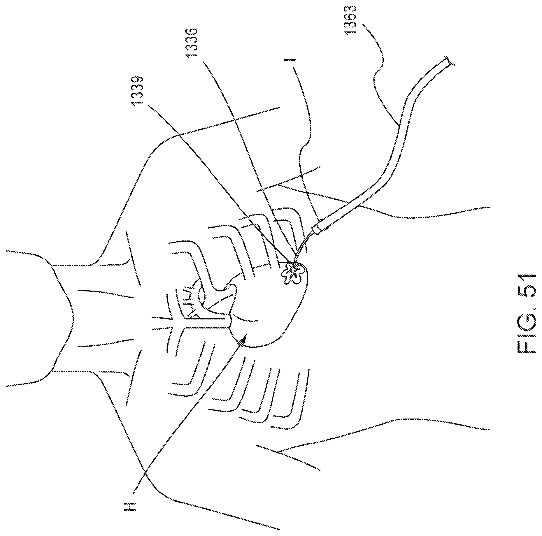
D00044

D00045

D00046

D00047

D00048

D00049

D00050

D00051

D00052

D00053

D00054

D00055

D00056

D00057

D00058

D00059

D00060

D00061

XML
uspto.report is an independent third-party trademark research tool that is not affiliated, endorsed, or sponsored by the United States Patent and Trademark Office (USPTO) or any other governmental organization. The information provided by uspto.report is based on publicly available data at the time of writing and is intended for informational purposes only.
While we strive to provide accurate and up-to-date information, we do not guarantee the accuracy, completeness, reliability, or suitability of the information displayed on this site. The use of this site is at your own risk. Any reliance you place on such information is therefore strictly at your own risk.
All official trademark data, including owner information, should be verified by visiting the official USPTO website at www.uspto.gov. This site is not intended to replace professional legal advice and should not be used as a substitute for consulting with a legal professional who is knowledgeable about trademark law.