Electrode Catheter With Incremental Advancement
GROSS; Yossi ; et al.
U.S. patent application number 16/302150 was filed with the patent office on 2020-06-11 for electrode catheter with incremental advancement. This patent application is currently assigned to PYTHAGORAS MEDICAL LTD.. The applicant listed for this patent is PYTHAGORAS MEDICAL LTD.. Invention is credited to Yossi GROSS, Yaron TAL, Yehuda ZADOK.
| Application Number | 20200179044 16/302150 |
| Document ID | / |
| Family ID | 59009713 |
| Filed Date | 2020-06-11 |


| United States Patent Application | 20200179044 |
| Kind Code | A1 |
| GROSS; Yossi ; et al. | June 11, 2020 |
ELECTRODE CATHETER WITH INCREMENTAL ADVANCEMENT
Abstract
Apparatus comprises: (a) a longitudinal member (32), having a distal portion (34); (b) a plurality of electrodes (38) disposed on the distal portion of the longitudinal member, such that a first electrode (38a) of the plurality of electrodes is disposed distally along the longitudinal member from a second electrode (38b) of the plurality of electrodes; and (c) a controller (40). The controller comprises an actuator, and circuitry (42) electrically connected to the electrodes via the longitudinal member. The actuator is configured to move the longitudinal member in discrete incremental movements such that for each incremental movement, (i) before the incremental movement the first electrode is disposed in a starting position, (ii) during each incremental movement the actuator moves second electrode toward the starting position, and (iii) at the end of each incremental movement the second electrode is stationary at the starting position.
| Inventors: | GROSS; Yossi; (Moshav Mazor, IL) ; ZADOK; Yehuda; (Holon, IL) ; TAL; Yaron; (Tel Mond, IL) | ||||||||||
| Applicant: |
|
||||||||||
|---|---|---|---|---|---|---|---|---|---|---|---|
| Assignee: | PYTHAGORAS MEDICAL LTD. Herzlia IL |
||||||||||
| Family ID: | 59009713 | ||||||||||
| Appl. No.: | 16/302150 | ||||||||||
| Filed: | May 15, 2017 | ||||||||||
| PCT Filed: | May 15, 2017 | ||||||||||
| PCT NO: | PCT/IL2017/050533 | ||||||||||
| 371 Date: | November 16, 2018 |
Related U.S. Patent Documents
| Application Number | Filing Date | Patent Number | ||
|---|---|---|---|---|
| 62338115 | May 18, 2016 | |||
| Current U.S. Class: | 1/1 |
| Current CPC Class: | A61B 5/6852 20130101; A61B 2018/00208 20130101; A61B 2018/165 20130101; A61B 2018/0016 20130101; A61B 2018/00732 20130101; A61B 2018/0072 20130101; A61B 2018/00839 20130101; A61B 5/6855 20130101; A61B 2018/00404 20130101; A61B 2018/1467 20130101; A61B 2018/1497 20130101; A61B 2018/00511 20130101; A61B 2018/00214 20130101; A61B 5/0215 20130101; A61B 5/6858 20130101; A61B 2018/00434 20130101; A61B 5/4893 20130101; A61B 18/1492 20130101; A61B 2018/162 20130101; A61B 2018/00577 20130101 |
| International Class: | A61B 18/14 20060101 A61B018/14 |
Claims
1. Apparatus for use with a blood vessel of a subject, the apparatus comprising: a longitudinal member, having a distal portion that is transluminally advanceable into the blood vessel; a plurality of electrodes disposed on the distal portion of the longitudinal member, such that a first electrode of the plurality of electrodes is disposed distally along the longitudinal member from a second electrode of the plurality of electrodes; and a controller, comprising: circuitry electrically connected to the electrodes via the longitudinal member, and an actuator, mechanically connected to the longitudinal member, and configured to move the longitudinal member in discrete incremental movements such that for each incremental movement, (a) before the incremental movement the first electrode is disposed in a starting position, (b) during each incremental movement the actuator moves second electrode toward the starting position of the first electrode, and (c) at the end of each incremental movement the second electrode is stationary at the starting position of the first electrode.
2. The apparatus according to claim 1, wherein: the plurality of electrodes comprises a third electrode and a fourth electrode, the third electrode is disposed distally along the longitudinal member from the fourth electrode, and the actuator is configured to move the longitudinal member in incremental movements such that for each incremental movement, (a) before the incremental movement the third electrode is disposed in a starting position, (b) during each incremental movement the actuator moves fourth electrode toward the starting position of the third electrode, and (c) at the end of each incremental movement the fourth electrode is stationary at the starting position of the third electrode.
3. The apparatus according to claim 1, wherein: the plurality of electrodes comprises a third electrode and a fourth electrode, the third electrode is disposed distally along the longitudinal member from the fourth electrode, and the actuator is configured to move the longitudinal member in incremental movements such that for each incremental movement, (a) before the incremental movement the third electrode is disposed in a starting position, (b) during each incremental movement the actuator moves fourth electrode toward the starting position of the third electrode, and (c) at the end of each incremental movement the fourth electrode is stationary at the starting position of the third electrode, wherein the circuitry is configured to, after each incremental movement, drive the first and third electrodes to apply ablative current, and to drive the second and fourth electrodes to apply excitatory current.
4. The apparatus according to claim 1, wherein the distal portion of the longitudinal member has an operational shape in which it is curved to define a helix, the plurality of electrodes is distributed in a helical arrangement along the distal portion of the longitudinal member, and the actuator is configured to move the second electrode into the starting position of the first electrode by advancing and rotating the longitudinal member.
5. The apparatus according to claim 1, wherein the actuator comprises a servomotor.
6. The apparatus according to claim 1, wherein the circuitry is configured to drive the first electrode to apply ablative current, and to drive the second electrode to apply excitatory current.
7. The apparatus according to claim 6, wherein the circuitry is configured to drive the first electrode to apply ablative current, and to drive the second electrode to apply excitatory current after each incremental movement.
8. The apparatus according to claim 6, wherein the circuitry is configured to configure the ablative current to have a frequency of 450-550 kHz.
9. The apparatus according to claim 6, wherein the circuitry is configured to configure the excitatory current to have a frequency of 20-500 Hz.
10. The apparatus according to claim 6, wherein the circuitry is configured to drive the first electrode to apply the ablative current independently from driving the excitatory current.
11.-19. (canceled)
Description
CROSS-REFERENCES TO RELATED APPLICATIONS
[0001] The present application is the US National Phase of PCT application IL2017/050533 to Yossi GROSS et al., filed May 15, 2017, entitled "HELICAL CATHETER," which published as WO 2017/199240, and which claims priority to U.S. provisional patent application 62/338,115 to Yossi GROSS et al., filed May 18, 2016, and entitled "HELICAL CATHETER," which is incorporated herein by reference.
FIELD OF THE INVENTION
[0002] Applications of the present invention relate generally to ablation of tissue. Some applications of the present invention relate more specifically to ablation of tissue of the renal artery.
BACKGROUND
[0003] Hypertension is a prevalent condition in the general population, particularly in older individuals. Sympathetic nervous pathways, such as those involving the renal nerve, are known to play a role in regulating blood pressure. Ablation of renal nerve tissue from the renal artery is a known technique for treating hypertension.
SUMMARY OF THE INVENTION
[0004] Apparatus and methods are provided for improving nerve ablation procedures, including inter alia by reducing the number of steps, the number of movements, and/or the amount of time required. The apparatus and methods may be particularly useful for renal nerve ablation procedures. For some applications, ablative current is applied by one electrode and excitatory current is applied by another electrode, without it being necessary to move the electrodes. The electrodes are then moved in a stepwise procession through the artery with which the nerve is associated.
[0005] Also described are techniques for applying current to the wall of an artery in a manner that emulates monopolar current application, but without the use of a skin-based return electrode.
[0006] There is therefore provided, in accordance with an application of the present invention, a method, including:
[0007] advancing into a blood vessel of a subject a distal portion of a longitudinal member having a plurality of electrodes disposed thereon, such that a first electrode of the plurality of electrodes is disposed at a starting position, the first electrode being disposed, along the distal portion, distally to a second electrode of the plurality of electrodes;
[0008] using a controller to drive the first electrode to apply an ablative current;
[0009] using the controller to drive the second electrode to apply an excitatory current; and
[0010] subsequently, moving the longitudinal member distally such that the second electrode moves toward the starting position of the first electrode, and stops at the starting position of the first electrode.
[0011] In an application, the distal portion of the longitudinal member has an operational shape in which it is curved to define a helix, the plurality of electrodes are distributed in a helical arrangement along the distal portion of the longitudinal member, and the step of moving the longitudinal member distally includes moving the longitudinal member distally and rotating at least the distal portion of the longitudinal member such that the second electrode moves toward the starting position of the first electrode, and stops at the starting position of the first electrode.
[0012] In an application, the method further includes, subsequently to the step of moving the longitudinal member:
[0013] using the controller to drive the first electrode to apply an ablative current to tissue distal to the starting position of the first electrode; and
[0014] using the controller to drive the second electrode to apply an excitatory current to tissue at the starting position of the first electrode.
[0015] There is further provided, in accordance with an application of the present invention, apparatus for use with a blood vessel of a subject, the apparatus including:
[0016] a longitudinal member, having a distal portion that is transluminally advanceable into the blood vessel;
[0017] a plurality of electrodes disposed on the distal portion of the longitudinal member, such that a first electrode of the plurality of electrodes is disposed distally along the longitudinal member from a second electrode of the plurality of electrodes; and a controller, including: [0018] circuitry electrically connected to the electrodes via the longitudinal member, and [0019] an actuator, mechanically connected to the longitudinal member, and configured to move the longitudinal member in discrete incremental movements such that for each incremental movement, (a) before the incremental movement the first electrode is disposed in a starting position, (b) during each incremental movement the actuator moves second electrode toward the starting position of the first electrode, and (c) at the end of each incremental movement the second electrode is stationary at the starting position of the first electrode.
[0020] In an application:
[0021] the plurality of electrodes includes a third electrode and a fourth electrode,
[0022] the third electrode is disposed distally along the longitudinal member from the fourth electrode, and
[0023] the actuator is configured to move the longitudinal member in incremental movements such that for each incremental movement, (a) before the incremental movement the third electrode is disposed in a starting position, (b) during each incremental movement the actuator moves fourth electrode toward the starting position of the third electrode, and (c) at the end of each incremental movement the fourth electrode is stationary at the starting position of the third electrode.
[0024] In an application:
[0025] the plurality of electrodes includes a third electrode and a fourth electrode,
[0026] the third electrode is disposed distally along the longitudinal member from the fourth electrode, and
[0027] the actuator is configured to move the longitudinal member in incremental movements such that for each incremental movement, (a) before the incremental movement the third electrode is disposed in a starting position, (b) during each incremental movement the actuator moves fourth electrode toward the starting position of the third electrode, and (c) at the end of each incremental movement the fourth electrode is stationary at the starting position of the third electrode,
wherein the circuitry is configured to, after each incremental movement, drive the first and third electrodes to apply ablative current, and to drive the second and fourth electrodes to apply excitatory current.
[0028] In an application, the distal portion of the longitudinal member has an operational shape in which it is curved to define a helix, the plurality of electrodes is distributed in a helical arrangement along the distal portion of the longitudinal member, and the actuator is configured to move the second electrode into the starting position of the first electrode by advancing and rotating the longitudinal member.
[0029] In an application, the actuator includes a servomotor.
[0030] In an application, the circuitry is configured to drive the first electrode to apply ablative current, and to drive the second electrode to apply excitatory current.
[0031] In an application, the circuitry is configured to drive the first electrode to apply ablative current, and to drive the second electrode to apply excitatory current after each incremental movement.
[0032] In an application, the circuitry is configured to configure the ablative current to have a frequency of 450-550 kHz.
[0033] In an application, the circuitry is configured to configure the excitatory current to have a frequency of 20-500 Hz.
[0034] In an application, the circuitry is configured to drive the first electrode to apply the ablative current independently from driving the excitatory current.
[0035] There is further provided, in accordance with an application of the present invention, apparatus for use with a blood vessel of a subject, the apparatus including:
[0036] a longitudinal member, having a distal portion that is transluminally advanceable into the blood vessel;
[0037] a plurality of electrodes disposed on the distal portion of the longitudinal member; and
[0038] a controller, including circuitry electrically connected to the electrodes via the longitudinal member, and having: [0039] a first state in which the controller drives one of the electrodes to apply ablative current, and configures the other electrodes not to serve as return electrodes for the ablative current, and [0040] a second state in which the controller drives one of the electrodes to apply ablative current, and configures more than one of the other electrodes to serve as return electrodes for the ablative current.
[0041] In an application, the distal portion of the longitudinal member has an operational shape in which it is curved to define a helix, and the plurality of electrodes are distributed in a helical arrangement along the distal portion of the longitudinal member.
[0042] In an application, the controller has a third state in which the controller drives one of the electrodes to apply ablative current, and configures more than one of the other electrodes to serve as return electrodes for the ablative current, wherein one of the electrodes that serves as a return electrode in the third state is the electrode that in the second state the controller drives to apply ablative current.
[0043] In an application, the electrode that in the first state the controller drives to apply ablative current is the same electrode as the electrode that in the second state the controller drives to apply ablative current.
[0044] In an application, the controller has another state in which the controller drives one of the electrodes to apply ablative current, and configures only one of the other electrodes to serve as a return electrode for the ablative current.
[0045] In an application, in the first state, the controller is configured to configure the ablative current to have a frequency of 450-550 kHz, and a power of 1-7 W.
[0046] The present invention will be more fully understood from the following detailed description of applications thereof, taken together with the drawings, in which:
BRIEF DESCRIPTION OF THE DRAWINGS
[0047] FIGS. 1A, 1B, 1C, and 1D are schematic illustrations of a method for use with a blood vessel of a subject, in accordance with some applications of the invention;
[0048] FIGS. 2A and 2B are schematic illustrations of a system for use with a blood vessel of a subject, in accordance with some applications of the invention; and
[0049] FIGS. 3A, 3B, and 3C are schematic illustrations of a system for use with a blood vessel of a subject, in accordance with some applications of the invention.
DETAILED DESCRIPTION OF EMBODIMENTS
[0050] It is possible to use an excitatory current (i.e., a current configured to induce action potentials in nerve tissue) in order to locate renal nerves, and to monitor the progress of ablation of these nerves. Changes in one or more physiological parameters of the subject in response to the excitatory current indicate that the electrode used to apply the excitatory current is in proximity to a renal nerve, and that renal nerve is still at least partly functioning. Such parameters are typically related to blood pressure and/or heart rate. Techniques for locating and/or monitoring ablation of renal nerves (and other nerves) are described in the following patent applications, which are incorporated herein by reference: [0051] PCT application publication WO 2014/068577 to Gross et al., filed Nov. 3, 2013, and entitled "Controlled tissue ablation," [0052] PCT application publication WO 2015/170281 to Gross et al., filed May 7, 2015, and entitled "Controlled tissue ablation techniques," [0053] U.S. patent application Ser. No. 14/794,737 to Gross et al., filed Jul. 8, 2015, and entitled "Electrical signal-based electrode-tissue contact Detection," which published as US 2017/0007157, [0054] U.S. patent application Ser. No. 14/972,756 to Gross et al., filed Dec. 17, 2015, and entitled "Transluminal electrode catheters, which published as US 2017/0172651" [0055] U.S. patent application Ser. No. 15/001,615 to Gross et al., filed Jan. 20, 2016, and entitled "Catheter guidance and procedure planning, which published as US 2017/0202614" and [0056] U.S. patent application Ser. No. 15/147,081 to Gross et al., filed May 5, 2016 and entitled "Techniques for use with nerve tissue," which published as US 2016/0324572.
[0057] Such techniques may be time-consuming, e.g., because multiple excitations and/or ablations are typically required, because frequent repositioning of the electrode catheter is typically required, and because it is typically necessary to allow the parameter(s) being measured to return to baseline before the next application of current.
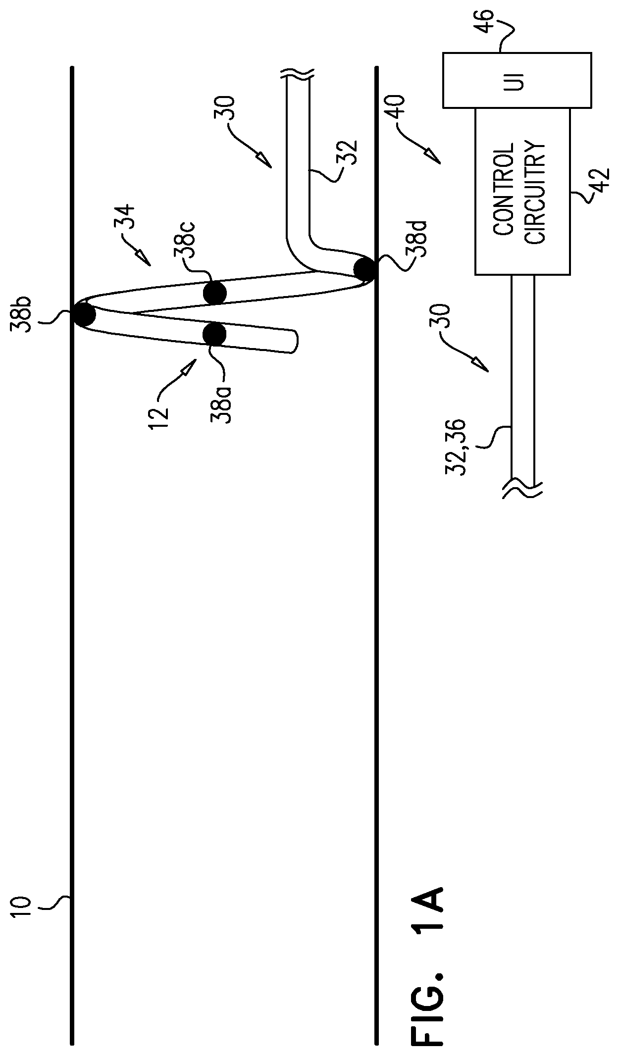
[0058] Reference is made to FIGS. 1A-D, which are schematic illustrations of a method for use with a blood vessel (e.g., a renal artery) 10 of a subject, in accordance with some applications of the invention. The method is hypothesized to reduce the number of steps required for a nerve-locating and/or nerve-ablating procedure by facilitating the application of ablative and excitatory current to artery 10 without movement of the electrode catheter. The method involves iteratively moving an electrode (e.g., an excitatory electrode) into the position within artery 10 that another electrode previously occupied.
[0059] An electrode catheter 30 comprises a longitudinal member 32, which has a distal portion 34 that is transluminally advanceable into blood vessel 10, and a proximal portion 36. Catheter 30 further comprises a plurality of electrodes 38 (e.g., a first electrode 38a, a second electrode 38b, a third electrode 38c, and a fourth electrode 38d) disposed on distal portion 34, typically distributed along member 32. For example, electrode 38a is disposed distally along longitudinal member 32 from electrode 38b. For example, along distal portion 34, electrode 38a is disposed distally to electrode 38b, which is disposed distally to electrode 38c, which is disposed distally to electrode 38d.
[0060] It is to be noted that, although catheter 30 is shown having four electrodes, for some applications the catheter comprises a different number of electrodes, such as two, three, five, six, seven, eight, or more. Similarly, although the helical shape of distal portion 34 is shown as having one helical turn, it may have more than one helical turn. Catheter 30 may in fact have more than one helical turn with more than four electrodes arranged in more than one helical turn along distal portion 34.
[0061] Distal portion 34 of longitudinal member 32 is advanced into blood vessel 10, such that a first electrode 38a of the plurality of electrodes is disposed at a starting position 12 of that electrode (FIG. 1A). (It is to be noted that the term "starting position" (including in the specification and in the claims) does not necessarily mean the first position in which the electrode is disposed after entering artery 10.) A controller 40 comprises control circuitry 42, which is electrically connected to electrodes 38 via longitudinal member 32. Controller 40 is used (e.g., by an operating physician) (i) to drive electrode 38a to apply an ablative current (i.e., to tissue adjacent to the electrode), and (ii) to drive electrode 38b to apply an excitatory current (i.e., to tissue adjacent to the electrode). The ablative and excitatory currents are therefore applied while catheter 30 and its electrodes remain in the same position. For some applications, the ablative and excitatory currents are applied generally at the same time. For some applications, the ablative and excitatory currents are applied independently of each other. A response of one or more physiological parameters to the excitatory current is measured.
[0062] Controller 40 is typically a programmed digital computing device comprising a central processing unit (CPU), random access memory (RAM), non-volatile secondary storage, such as a hard drive or CD ROM drive, network interfaces, and/or peripheral devices. Program code, including software programs, and/or data are loaded into the RAM for execution and processing by the CPU and results are generated for display, output, transmittal, or storage, as is known in the art. Such program code and/or data, when provided to the controller, produce a machine or special-purpose computer, configured to perform the tasks described herein. Controller 40 further comprises a user interface (UI) 46 via which the operating physician interacts with (e.g., operates) the controller. For example, UI 46 may comprise one or more input devices (e.g., buttons and/or levers) and/or one or more output devices (e.g., dials and/or displays). For some applications, controller 40 is electrically connected to a blood pressure sensor (which may be disposed on longitudinal member 32; not shown), and receives blood pressure measurements, thereby facilitating the identification and/or quantification of the response of the one or more physiological parameters to the excitatory current.
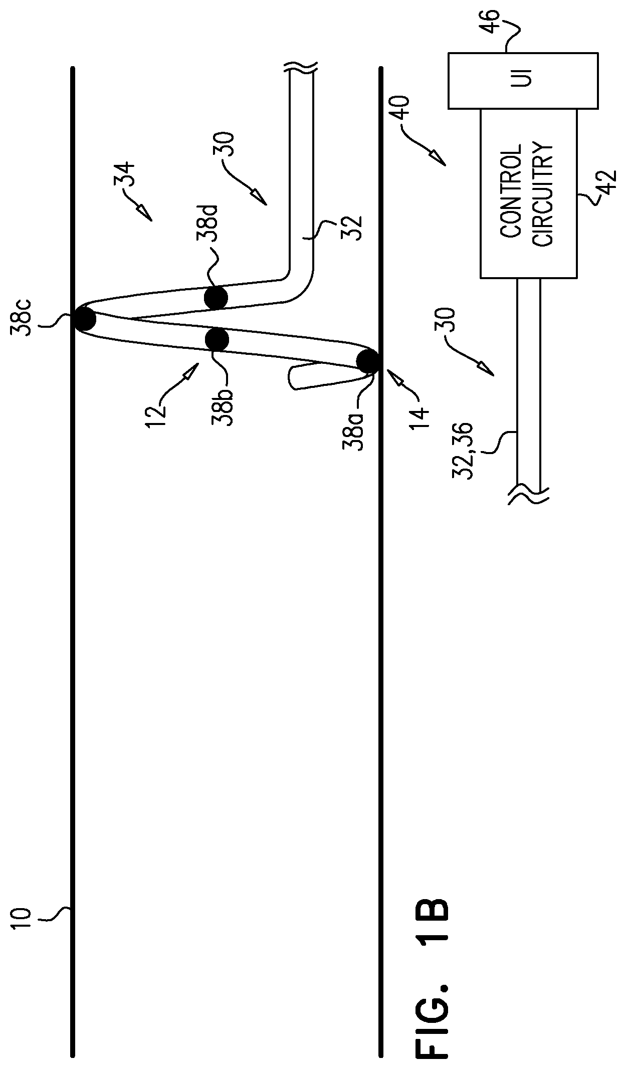
[0063] Longitudinal member 32 is subsequently moved distally such that electrode 38b moves toward the starting position 12 of electrode 38a, and stops there (FIG. 1B). As shown, this also causes electrode 38a to move into a new position 14, electrode 38c to move into the starting position of electrode 38b, and electrode 38d to move into the starting position of electrode 38d. In this position, controller 40 is again used (i) to drive electrode 38a to apply an ablative current, and (ii) to drive electrode 38b to apply an excitatory current, and again, a response of one or more physiological parameters to the excitatory current is measured. As described hereinabove, the ablative and excitatory currents are applied while catheter 30 and its electrodes remain in the same position (and optionally generally at the same time). This reduces the number of steps (and therefore time) required, compared to a similar procedure in which it is necessary to move the electrode catheter between each application of current.
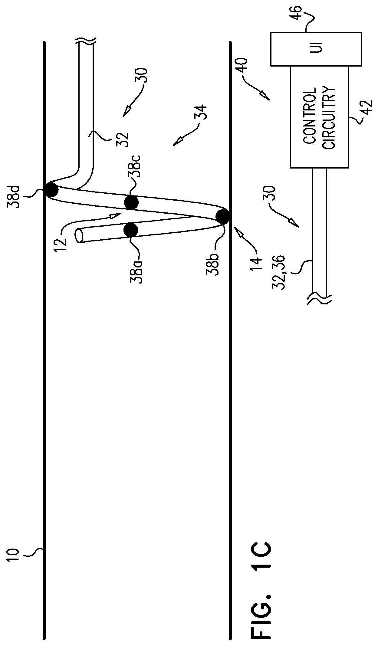
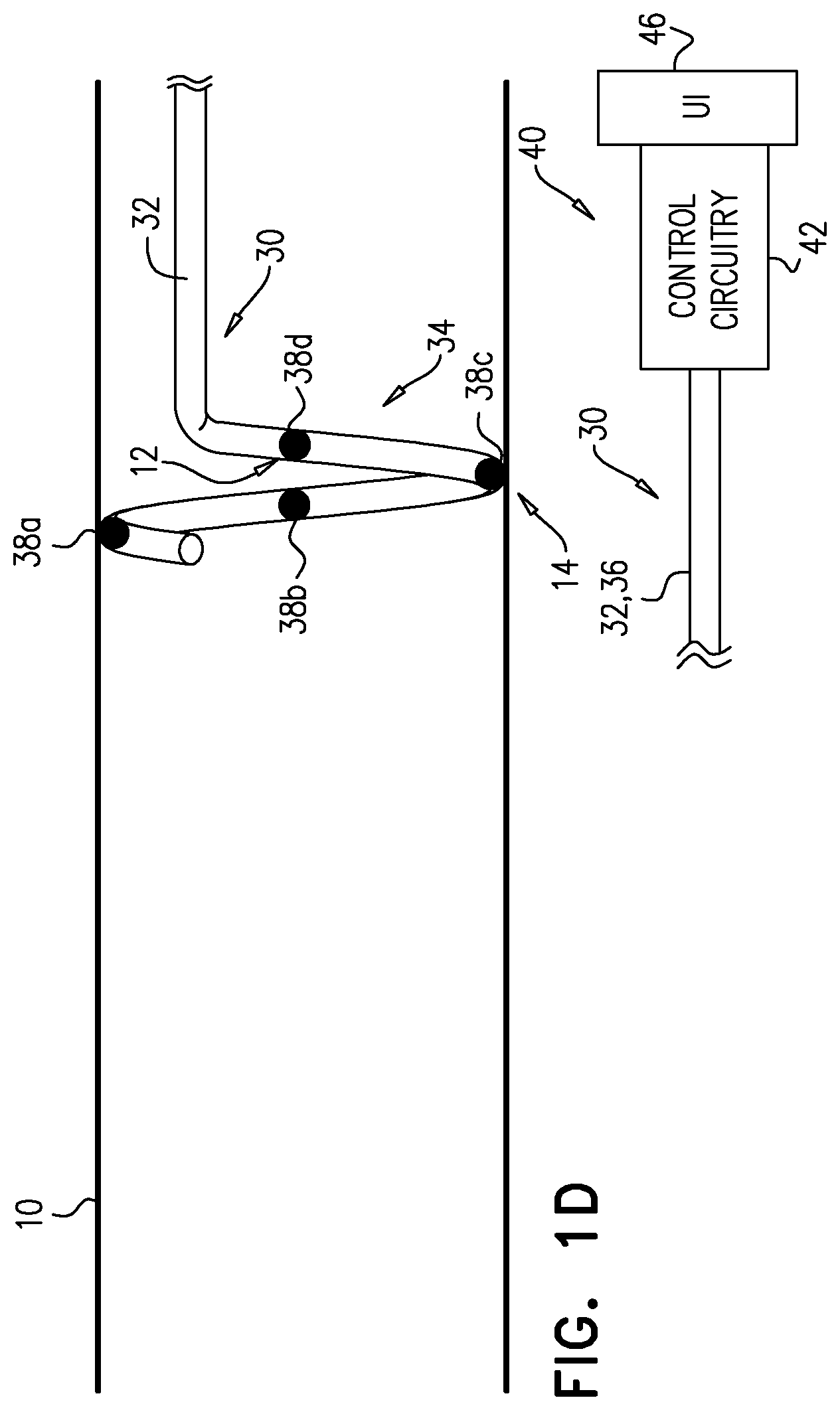
[0064] FIGS. 1C and 1D show further iterative steps in this process.
[0065] For some applications, the movement of longitudinal member 32 distally is performed manually. For some such applications, the longitudinal member (e.g., proximal portion 36 thereof) has markers that are spaced according to the spacing of electrodes 38, such that the operating physician can advance the longitudinal member by one marker, knowing that this will place each electrode in the position that was previously occupied by another electrode. For some applications (e.g., as described hereinbelow with reference to FIGS. 2A-B) the movement of longitudinal member 32 distally is at least partly automated.
[0066] For some applications, and as shown, distal portion 34 of longitudinal member 32 has an operational shape in which it is curved to define a helix, and electrodes 38, which are distributed along distal portion 34, are thereby distributed in a helical arrangement. This is hypothesized to facilitate ablation at many circumferential positions around artery 10, but without ablating in a closed circle, which for some applications may cause narrowing and/or weakening of the artery. For such applications, the step of moving the longitudinal member 32 distally comprises moving the longitudinal member distally and rotating at least distal portion 34 such that electrode 38b moves (e.g., in a helical path) toward the starting position of electrode 38a, and stops there.
[0067] For some applications, the step of moving longitudinal member 32 distally comprises moving the longitudinal member distally without rotating distal portion 34. For some such applications, distal portion 34 may be helical, as shown. Alternatively, for some such applications distal portion 34 may have a different form, such as a basket or balloon.
[0068] The above description of the method shown in FIGS. 1A-D relates to two electrodes. As described hereinabove, catheter 30 may comprise a different number of electrodes (e.g., four electrodes, as shown). The method described with reference to FIGS. 1A-D is also applicable to such numbers of electrodes. Two such applications are as follows:
[0069] (1) More proximal electrodes may be used to repeat the ablation-excitation process at a given site on artery 10. For example, if it is determined that the physiological parameter responds to the excitatory current applied by electrode 38b to starting position 12 (FIG. 1B), another application of ablative current may be applied via electrode 38c when it is disposed at position 12 (FIG. 1C), and another application of excitatory current may be subsequently applied via electrode 38d when that electrode is disposed at position 12 (FIG. 1D).
[0070] (2) More than one electrode may be used to apply a current. That is, application of the ablative and/or excitatory current may be performed in a bipolar manner. For example, ablative current may be applied between electrodes 38a and 38c, and excitatory current may be applied between electrodes 38b and 38d.
[0071] For some applications, the ablative current has a frequency of 450-550 kHz and/or a power of 1-7 W. For some applications, the ablative current has a sinusoidal waveform.
[0072] For some applications, the excitatory current has a frequency of 20-500 Hz and/or a stimulation amplitude of 1-50 mA. For some applications, the excitatory current has a rectangular waveform.
[0073] Reference is now made to FIGS. 2A-B, which are schematic illustrations of a system 20 for use with artery 10 of a subject, in accordance with some applications of the invention. System 20 comprises electrode catheter 30 and a controller 60 for the electrode catheter. Controller 60 is typically as described for controller 40, except where noted. System 20 is typically used to facilitate the method described with reference to FIGS. 1A-D, and/or methods similar thereto.
[0074] Controller 60 comprises control circuitry 62, which is electrically connected to electrodes 38 via longitudinal member 32. Controller 60 also comprises a user interface (UI) 66, via which the operating physician interacts with the controller. Controller 60 further comprises an actuator 64, which is mechanically connected to longitudinal member 32, and is configured to move the longitudinal member in discrete incremental movements such that for each incremental movement, (a) before the incremental movement the first electrode is disposed in a starting position, (b) during each incremental movement the actuator moves second electrode toward the starting position of the first electrode, and (c) at the end of each incremental movement the second electrode is stationary at the starting position of the first electrode.
[0075] In order to perform the movements of catheter 30 described with reference to FIGS. 1A-D, the operating physician triggers actuator 64 (e.g., via UI 66) such that the actuator moves longitudinal member 32 the discrete increment (e.g., distally, or distally and rotationally). The arrows in FIG. 2B show the movement of longitudinal member 32 and electrodes 38 during the discrete incremental movement that will occur when the operating physician next triggers actuator 64. Each incremental movement is typically pre-determined, e.g., based on known dimensions of longitudinal member 32 and spacing of electrodes 38. For some applications, actuator 64 comprises a servomotor. The use of controller 60 to automatically move the longitudinal member such that each electrode moves into the position that the electrode distal to it previously occupied, reduces the requirement for imaging (e.g., fluoroscopy) during the procedure.
[0076] The applications of ablative and excitatory currents are also typically applied by the operating physician via UI 66.
[0077] Reference is again made to FIGS. 1A-2B. For some applications, the electrodes are differently configured for application of ablative or excitatory currents. For some applications, all the electrodes are identical other than in their respective connection to the controller, which differentially drives the electrodes to apply the respective type of current.
[0078] Catheter 30 is described as having its distalmost electrode (electrode 38a) apply ablative current, and for the electrode proximal to that (electrode 38b) apply excitatory current. However, for some applications, the distalmost electrode applies excitatory current, and the electrode proximal to that applies ablative current. For example, the controller may drive electrode 38a to apply excitatory current, electrode 38b to apply ablative current, electrode 38c to apply excitatory current, and so on. For such applications, each site in artery 10 is thereby tested (by applying excitatory current and measuring the physiological response) before any ablative current is applied to it, thereby reducing the number of unnecessary applications of ablative current. An exemplary procedure may be as follows:
[0079] (1) Distal portion 34 of longitudinal member 32 is advanced into artery 10, electrode 38a is driven to apply excitatory current. If the physiological response to the excitatory current is insufficient or absent, the catheter is repositioned (e.g., advanced distally) and excitatory current is reapplied via electrode 38a, iteratively until a sufficient physiological response is detected, indicating that electrode 38a is in proximity to a viable renal nerve. For this example, let the position of electrode 38a in which it successfully excited the nerve, be called position A.
[0080] (2) Distal portion 34 is advanced distally such that electrode 38b moves to and stops at position A, and electrode 38a moves to and stops at a new position B.
[0081] (3) Electrode 38a is driven to apply excitatory current at position B, and electrode 38b is driven to apply ablative current at position A. Typically, distal portion 34 is not moved between the application of these two currents. For some applications, these two currents are applied at generally the same time. Therefore, electrode 38a tests position B, and electrode 38b ablates at position A, without it being necessary to move catheter 30 between these functions being performed.
[0082] (4) Distal portion 34 is advanced distally, such that electrode 38a moves to a new position C, electrode 38b moves to position B, and electrode 38c moves to position A.
[0083] (5) Electrode 38a is driven to apply excitatory current at position C, and electrode 38c is driven to apply excitatory current at position A. Additionally, if the previous excitation by electrode 38a at position B successfully affected the physiological parameter, then electrode 38b is driven to apply ablative current at position B. Typically, distal portion 34 is not moved between the application of these two or three currents. For some applications, these two or three currents are applied at generally the same time. Therefore, electrode 38a tests position C, electrode 38c re-tests position A (to see if the ablative current successfully denervated that location), and optionally electrode 38b ablates at position B, without it being necessary to move catheter 30 between these functions being performed.
[0084] These steps are iteratively repeated along the artery, e.g., to positions D, E, F, G, and so on. For applications in which another electrode, disposed proximally from electrode 38c, is configured to apply ablative current (e.g., electrode 38d), if the re-testing of position A by electrode 38c determines that the first ablation of position A by electrode 38a was unsuccessful, then this other electrode may be used to re-apply ablative current at position A. Increasing the number of ablating and exciting electrodes along distal portion 34 allows an increased number of re-testing and re-ablating steps using this technique.
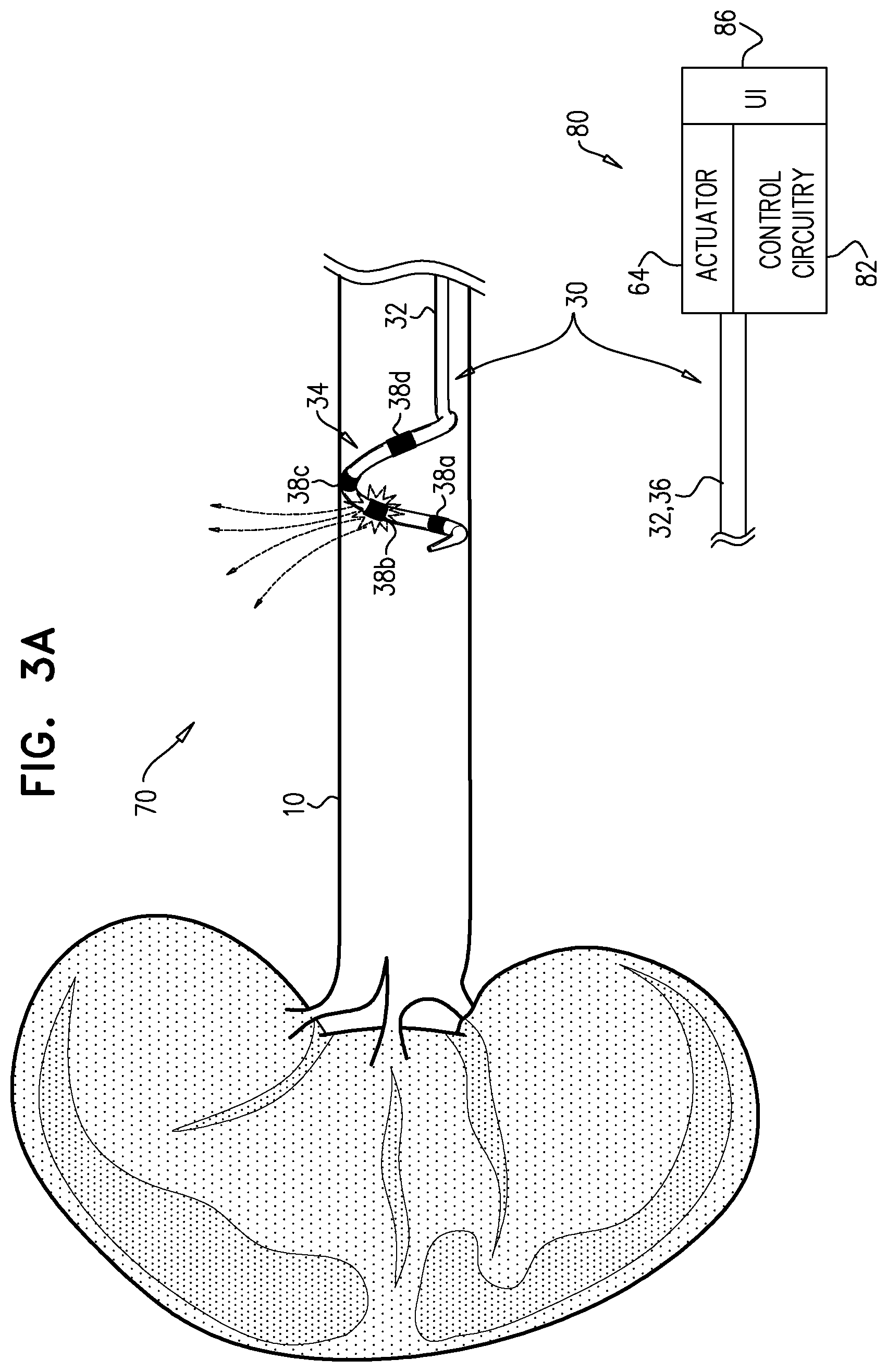
[0085] Reference is made to FIGS. 3A-C, which are schematic illustrations of a system 70 for use with artery 10 of a subject, in accordance with some applications of the invention. System 70 comprises electrode catheter 30 and a controller 80 for the electrode catheter. Alternatively, system 70 may comprise a different electrode catheter. Controller 80 is typically as described for controller 60, except where noted. Controller 80 comprises control circuitry 82, which is electrically connected to electrodes 38 via longitudinal member 32. Controller 80 also comprises a UI 86, via which the operating physician interacts with the controller. Controller 80 may or may not comprise actuator 64 (described hereinabove).
[0086] Controller 80 has a first state in which it drives one of electrodes 38 to apply ablative current, and configures the other electrodes not to serve as return electrodes for the ablative current. (It is to be noted that in this context the terms first state, second state, third state etc. are used to facilitate reference to the different states, and should not be understood as implying a particular order in which these states occur or are used). FIG. 3A shows system 70 with controller 80 in the first state, driving electrode 38b to apply ablative current, with electrodes 38a, 38c, and 38d not serving as return electrodes. In the first state, a skin-mounted return electrode is typically used. The ablative current is represented by dotted arrows, moving deeper into the surrounding tissue, e.g., toward the skin-mounted return electrode. This is typically referred to as monopolar ablation.
[0087] It is understood by the inventors that for some sites within a particular renal artery, monopolar ablation is preferable, and for some sites, bipolar ablation is preferable. For some applications, this is determined during the excitation steps described hereinabove, and/or during procedures described in the patent applications cited hereinabove, and incorporated herein by reference.
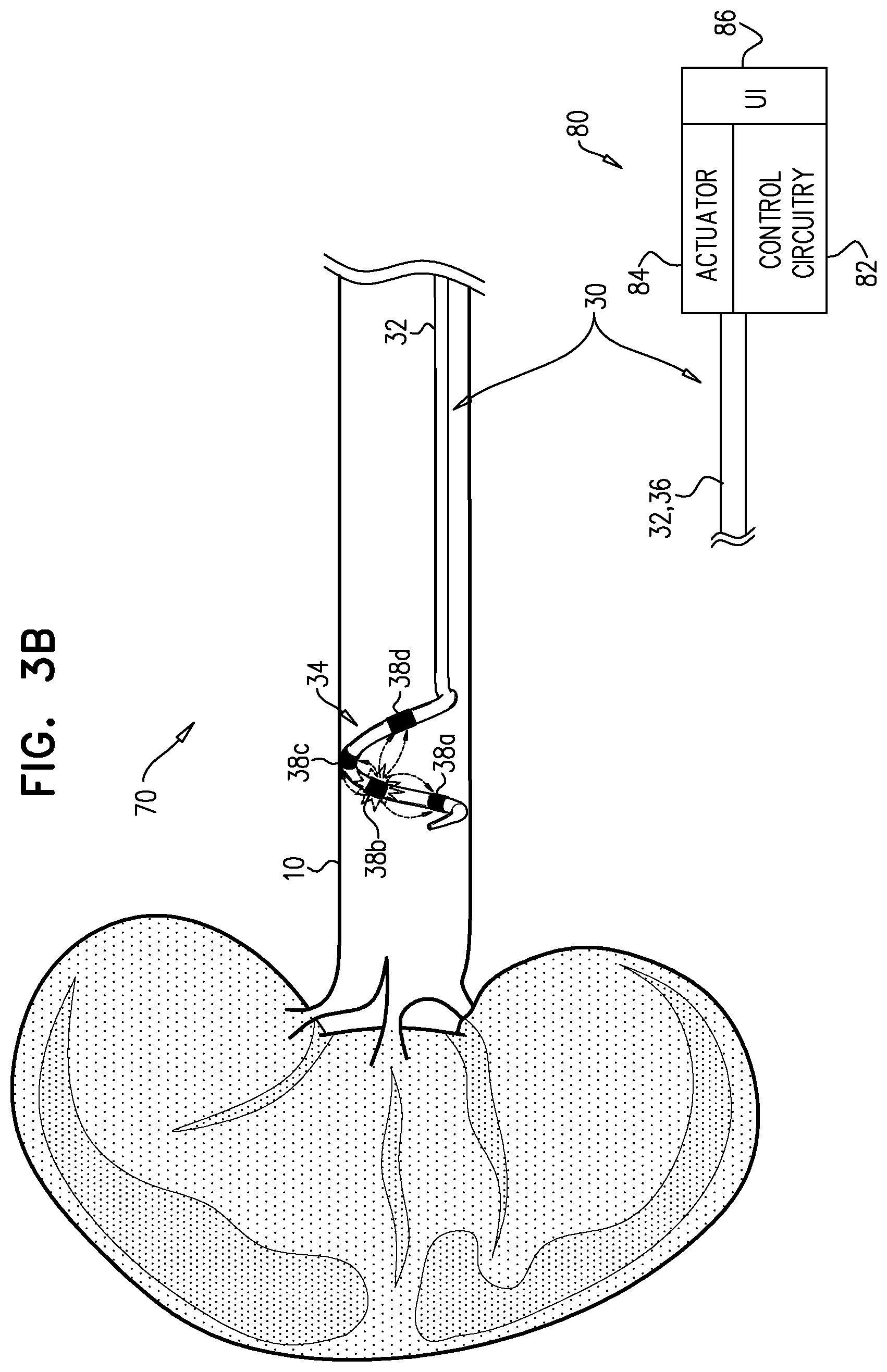
[0088] Controller 80 has a second state in which it drives one of electrodes 38 to apply ablative current, and configures more than one of the other electrodes to serve as return electrodes for the ablative current. FIG. 3B shows system 70 with controller 80 in the second state, driving electrode 38b to apply ablative current, with electrodes 38a, 38c, and 38d serving as return electrodes. The ablative current is represented by dotted arrows, moving from electrode 38b toward the three return electrodes. In classical bipolar ablation, ablative current is driven between two electrodes, and current-density at the return electrode is typically similar to that at the current-applying electrode. Frequently, the resulting lesion may extend between the two electrodes, or a separate lesion may be formed at the return electrode. In the second state of controller 80, the current applied by the current-applying electrode (electrode 38b) spreads toward the more-than-one return electrodes, such that the current-density at each of the return electrodes is lower than at the current-applying electrode. It is hypothesized by the inventors that the effect of this technique is similar to that of monopolar ablation, but advantageously doesn't require a skin-mounted electrode. Control and reliability are improved because the distance and tissue between the current-applying electrode and the return electrodes is less variable than with a skin-mounted return electrode. Additionally, in contrast to bipolar ablation, the spreading of current to more than one return electrodes reduces a likelihood of causing extended and/or secondary lesions.
[0089] For some applications, the same electrode (as shown, electrode 38b) is driven to apply the ablative current in both the first and second states.
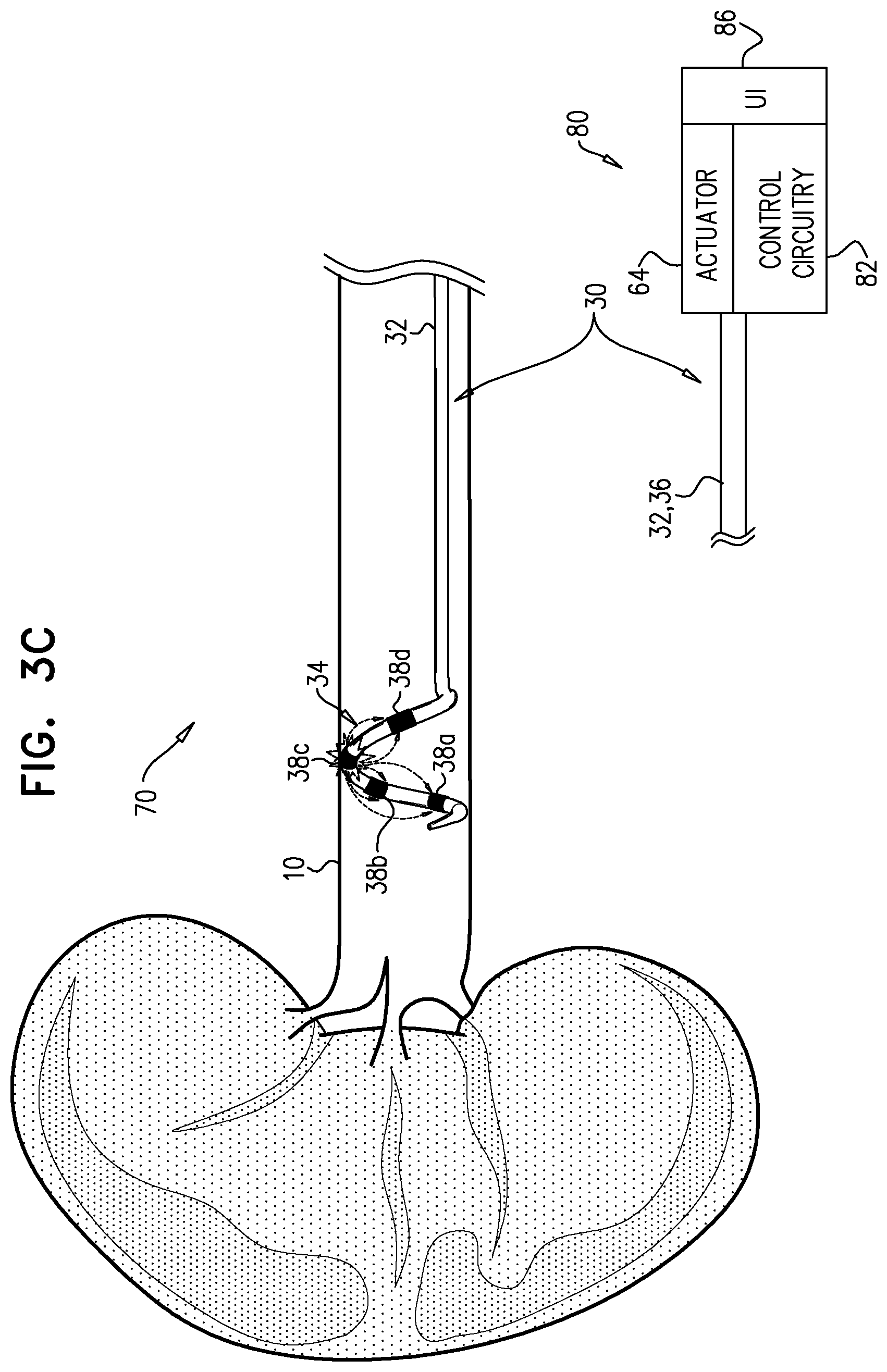
[0090] For some applications, controller 80 has a third state in which it drives one of electrodes 38 to apply ablative current, and configures more than one of the other electrodes to serve as return electrodes for the ablative current. One of the electrodes that serves as a return electrode in the third state is the electrode that in the second state controller 80 drives to apply ablative current. FIG. 3C shows system 70 with controller 80 in the third state, driving electrode 38c to apply ablative current, with electrode 38b serving as one of the return electrodes.
[0091] For some applications, controller 80 has another state in which only one of the other electrodes serves as a return electrode, thereby performing classical bipolar ablation.
[0092] Although the techniques described with reference to FIGS. 3A-C refer to application of ablative current, these same techniques may be used for application of excitatory current, mutatis mutandis.
[0093] Reference is again made to FIGS. 1A-3C. Although the apparatus and methods described herein are described for iteratively moving distal portion 34 in a distal direction (e.g., from an ostium of renal artery 10 toward a kidney), they may alternatively be used by moving the distal portion in a proximal direction, mutatis mutandis.
[0094] Reference is again made to FIGS. 1A-3C. Although not shown, distal portion 34 is typically drawn toward its central longitudinal axis (and thereby away from the wall of artery 10) before each movement being moved distally (or proximally) through the artery. For example, when distal portion 34 is helical, this is typically achieved by straightening the helix. For some applications, distal portion 34 is biased to assume a relatively straight shape, and assumes its helical shape upon insertion of a pre-shaped rod into the distal portion.
[0095] Reference is again made to FIGS. 1A-3C. For some applications electrodes 38 are rings that circumscribe longitudinal member 32. For some applications, electrodes 38 do not circumscribe longitudinal member 32, and instead are disposed on the longitudinal member such that when distal portion 34 assumes the helical shape, they are disposed radially outward from the longitudinal member such that they face the wall of the blood vessel.
[0096] It will be appreciated by persons skilled in the art that the present invention is not limited to what has been particularly shown and described hereinabove. Rather, the scope of the present invention includes both combinations and subcombinations of the various features described hereinabove, as well as variations and modifications thereof that are not in the prior art, which would occur to persons skilled in the art upon reading the foregoing description.
* * * * *
D00000
D00001
D00002
D00003
D00004
D00005
D00006
D00007
D00008
D00009
XML
uspto.report is an independent third-party trademark research tool that is not affiliated, endorsed, or sponsored by the United States Patent and Trademark Office (USPTO) or any other governmental organization. The information provided by uspto.report is based on publicly available data at the time of writing and is intended for informational purposes only.
While we strive to provide accurate and up-to-date information, we do not guarantee the accuracy, completeness, reliability, or suitability of the information displayed on this site. The use of this site is at your own risk. Any reliance you place on such information is therefore strictly at your own risk.
All official trademark data, including owner information, should be verified by visiting the official USPTO website at www.uspto.gov. This site is not intended to replace professional legal advice and should not be used as a substitute for consulting with a legal professional who is knowledgeable about trademark law.