Electrosurgical Forceps
Sims; Grant T. ; et al.
U.S. patent application number 16/210218 was filed with the patent office on 2020-06-11 for electrosurgical forceps. The applicant listed for this patent is COVIDIEN LP. Invention is credited to Kelley D. Goodman, Craig V. Krastins, Robert F. Mccullough, JR., Daniel W. Mercier, Jennifer L. Rich, Grant T. Sims.
| Application Number | 20200179035 16/210218 |
| Document ID | / |
| Family ID | 70970722 |
| Filed Date | 2020-06-11 |


| United States Patent Application | 20200179035 |
| Kind Code | A1 |
| Sims; Grant T. ; et al. | June 11, 2020 |
ELECTROSURGICAL FORCEPS
Abstract
An electrosurgical forceps includes first and second shaft members pivotably coupled to one another via a pivot member such that pivoting of the first and second shaft members between spaced-apart and approximated positions pivots jaw members thereof between open and closed positions. A knife is translatable between retracted and extended positions. The knife has a stop to prevent distal movement of the knife beyond the extended position.
| Inventors: | Sims; Grant T.; (Boulder, CO) ; Goodman; Kelley D.; (Erie, CO) ; Krastins; Craig V.; (Arvada, CO) ; Mccullough, JR.; Robert F.; (Boulder, CO) ; Rich; Jennifer L.; (Parker, CO) ; Mercier; Daniel W.; (Erie, CO) | ||||||||||
| Applicant: |
|
||||||||||
|---|---|---|---|---|---|---|---|---|---|---|---|
| Family ID: | 70970722 | ||||||||||
| Appl. No.: | 16/210218 | ||||||||||
| Filed: | December 5, 2018 |
| Current U.S. Class: | 1/1 |
| Current CPC Class: | A61B 18/1492 20130101; A61B 2018/00577 20130101; A61B 18/1442 20130101; A61B 18/1445 20130101; A61B 2018/00607 20130101; A61B 2018/1455 20130101; A61B 18/085 20130101; A61B 2018/0063 20130101; A61B 2018/146 20130101; A61B 2018/00589 20130101; A61B 2018/00601 20130101; A61B 18/1206 20130101 |
| International Class: | A61B 18/14 20060101 A61B018/14; A61B 18/12 20060101 A61B018/12; A61B 18/08 20060101 A61B018/08 |
Claims
1. An electrosurgical forceps, comprising: a first shaft member; a second shaft member pivotably coupled to the first shaft member; a first jaw member secured to and extending distally from the first shaft member; a second jaw member secured to and extending distally from the second shaft member, the first jaw member including: a jaw frame; an insulative spacer disposed on the jaw frame and defining a longitudinally-extending channel; and a tissue-contacting plate disposed on the insulative spacer; and a knife selectively translatable through the first shaft member from a retracted position to an extended position in which the knife extends at least partially between the first and second jaw members, the knife including a distal edge having a sharp, upper segment and a dull, lower segment depending from the upper segment, the lower segment configured to abut the insulative spacer when the knife is in the extended position.
2. The electrosurgical forceps according to claim 1, wherein the lower segment of the distal edge of the knife protrudes distally beyond the upper segment.
3. The electrosurgical forceps according to claim 1, wherein the upper segment of the distal edge of the knife extends at an oblique angle relative to a longitudinal axis defined by the knife, and the lower segment is perpendicular relative to the longitudinal axis.
4. The electrosurgical forceps according to claim 1, wherein the lower segment of the distal edge of the knife is received in the channel of the insulative spacer, and the upper segment is received in a longitudinally-extending channel defined by the tissue-contacting plate.
5. The electrosurgical forceps according to claim 1, wherein the lower segment of the distal edge of the knife is configured to abut an inner peripheral surface of the insulative spacer upon the knife moving to the extended position, the inner peripheral surface of the insulative spacer defining an outer periphery of the channel.
6. An electrosurgical forceps, comprising: a first shaft member having a first inner frame; a second shaft member pivotably coupled to the first shaft member; a first jaw member secured to and extending distally from the first shaft member; a second jaw member secured to and extending distally from the second shaft member; a knife selectively translatable through the first shaft member from a retracted position to an extended position in which the knife extends at least partially between the first and second jaw members; and an elongate shell attached to a lateral side of the first inner frame and defining a longitudinally-extending passageway configured for slidable receipt of the knife therethrough.
7. The electrosurgical forceps according to claim 6, wherein the elongate shell has an inner surface that defines the passageway, the inner surface configured to permit movement of the knife along a longitudinal axis defined by the knife and resist lateral and vertical movement of the knife relative to the longitudinal axis.
8. The electrosurgical forceps according to claim 6, wherein the elongate shell is fabricated from plastic.
9. The electrosurgical forceps according to claim 6, wherein the knife has a blade stop protruding outwardly therefrom configured to abut a proximal edge of the elongate shell when the knife moves to the extended position to prevent further distal movement of the knife along the passageway.
10. The electrosurgical forceps according to claim 6, wherein the elongate shell has a connection tab extending laterally therefrom, the connection tab configured to engage in a correspondingly shaped aperture defined in the lateral side of the first inner frame.
11. The electrosurgical forceps according to claim 6, wherein the elongate shell has a rectangular shape.
Description
BACKGROUND
[0001] The present disclosure relates to electrosurgical instruments and, more particularly, to electrosurgical forceps for grasping, treating, and/or dividing tissue.
TECHNICAL FIELD
[0002] A surgical forceps is a plier-like instrument which relies on mechanical action between its jaws to grasp tissue. Electrosurgical forceps utilize both mechanical clamping action and electrical energy to treat tissue, e.g., coagulate, cauterize, and/or seal tissue.
[0003] Typically, once tissue is treated, the surgeon has to accurately sever the treated tissue. Accordingly, many electrosurgical forceps have been designed which incorporate a knife configured to effectively sever tissue after the tissue is treated.
SUMMARY
[0004] As used herein, the term "distal" refers to the portion that is being described which is further from a surgeon, while the term "proximal" refers to the portion that is being described which is closer to a surgeon. Further, to the extent consistent, any of the aspects described herein may be used in conjunction with any or all of the other aspects described herein.
[0005] As used herein, the terms parallel and perpendicular are understood to include relative configurations that are substantially parallel and substantially perpendicular up to about +/-10 degrees from true parallel and true perpendicular.
[0006] An electrosurgical forceps provided in accordance with aspects of the present disclosure includes a first shaft member, a second shaft member pivotably coupled to the first shaft member, a first jaw member secured to and extending distally from the first shaft member, a second jaw member secured to and extending distally from the second shaft member, and a knife. The first jaw member includes a jaw frame, an insulative spacer disposed on the jaw frame and defining a longitudinally-extending channel, and a tissue-contacting plate disposed on the insulative spacer. The knife is selectively translatable through the first shaft member from a retracted position to an extended position in which the knife extends at least partially between the first and second jaw members. The knife includes a distal edge having a sharp, upper segment and a dull, lower segment depending from the upper segment. The lower segment is configured to abut the insulative spacer when the knife is in the extended position.
[0007] In aspects, the lower segment of the distal edge of the knife may protrude distally beyond the upper segment.
[0008] In further aspects, the upper segment of the distal edge of the knife may extend at an oblique angle relative to a longitudinal axis defined by the knife, and the lower segment may be perpendicular relative to the longitudinal axis.
[0009] In some aspects, the lower segment of the distal edge of the knife may be received in the channel of the insulative spacer, and the upper segment may be received in a longitudinally-extending channel defined by the tissue-contacting plate.
[0010] In other aspects, the lower segment of the distal edge of the knife may be configured to abut an inner peripheral surface of the insulative spacer upon the knife moving to the extended position. The inner peripheral surface of the insulative spacer may define an outer periphery of the channel.
[0011] In another aspect of the present disclosure, an electrosurgical forceps is provided that includes a first shaft member having a first inner frame, a second shaft member pivotably coupled to the first shaft member, a first jaw member secured to and extending distally from the first shaft member, a second jaw member secured to and extending distally from the second shaft member, a knife, and an elongate shell attached to a lateral side of the first inner frame. The knife is selectively translatable through the first shaft member from a retracted position to an extended position in which the knife extends at least partially between the first and second jaw members. The elongate shell defines a longitudinally-extending passageway configured for slidable receipt of the knife therethrough.
[0012] In aspects, the elongate shell may have an inner surface that defines the passageway. The inner surface may be configured to permit movement of the knife along a longitudinal axis defined by the knife and resist lateral and vertical movement of the knife relative to the longitudinal axis.
[0013] In further aspects, the elongate shell may be fabricated from plastic.
[0014] In other aspects, the knife may have a blade stop protruding outwardly therefrom configured to abut a proximal edge of the elongate shell when the knife moves to the extended position to prevent further distal movement of the knife along the passageway.
[0015] In some aspects, the elongate shell may have a connection tab extending laterally therefrom and configured to engage a correspondingly shaped aperture defined in the lateral side of the first inner frame.
[0016] In aspects, the elongate shell may have a rectangular shape.
BRIEF DESCRIPTION OF THE DRAWINGS
[0017] Various aspects and features of the present disclosure are described hereinbelow with reference to the drawings wherein like numerals designate identical or corresponding elements in each of the several views:
[0018] FIG. 1 is a side, perspective view of an electrosurgical forceps provided in accordance with aspects of the present disclosure;
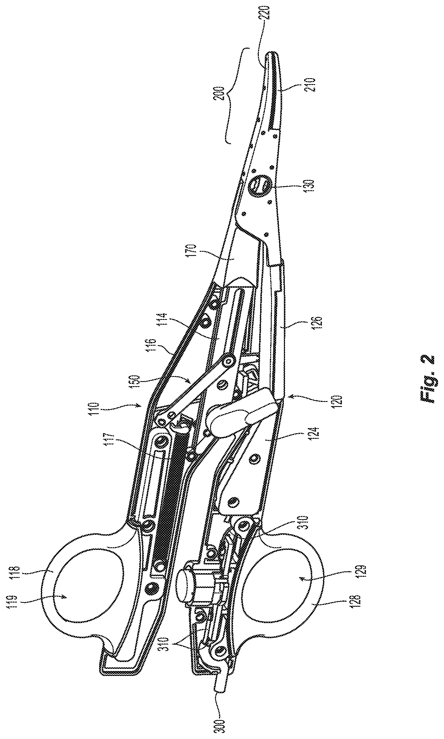
[0019] FIG. 2 is a perspective view from one side of the forceps of FIG. 1 with portions of outer housings of first and second shaft members removed to illustrate the internal components therein;
[0020] FIG. 3 is a side, perspective view of the forceps of FIG. 1 with portions removed to illustrate a knife within an inner frame of the forceps;
[0021] FIG. 4 is a side, perspective view of the inner frame of the first shaft member separated from a knife guide;
[0022] FIG. 5 is a side, cross-sectional view of the knife guide of FIG. 4;
[0023] FIG. 6 is a side, perspective view of a jaw member of the forceps;
[0024] FIG. 7 is a side, perspective view of the jaw member of FIG. 6 with a tissue-contacting plate removed therefrom to reveal an insulative spacer;
[0025] FIG. 8 is a side view of the knife of the forceps;
[0026] FIG. 9 is a longitudinal cross-sectional view of a distal end of the jaw member of FIG. 6 illustrating the knife in an extended position; and
[0027] FIG. 10 is side view of a distal end of another embodiment of the knife of the forceps.
DETAILED DESCRIPTION
[0028] Referring to FIGS. 1 and 2, a forceps 100 provided in accordance with the present disclosure generally includes first and second shaft members 110, 120 and an end effector assembly 200. Shaft members 110, 120 each have a proximal end portion 112a, 122a and a distal end portion 112b, 122b. End effector assembly 200 includes first and second jaw members 210, 220 extending from distal end portions 112b, 122b of shaft members 110, 120, respectively. Forceps 100 further includes a pivot member 130 pivotably coupling first and second shaft members 110, 120 with one another, a knife 140 (FIGS. 3 and 8), a knife deployment mechanism 150 for selectively deploying the knife 140 relative to end effector assembly 200, a knife lockout 170 for inhibiting deployment of knife 140 prior to sufficient closure of jaw members 210, 220, and a switch assembly 180 for enabling the selective supply of electrosurgical energy to end effector assembly 100. An electrosurgical cable 300 electrically couples forceps 100 to a source of energy (not shown), e.g., an electrosurgical generator, to enable the supply of electrosurgical energy to jaw members 210, 220 of end effector assembly 200 upon activation of switch assembly 180.
[0029] Continuing with reference to FIGS. 1 and 2, each shaft member 110, 120 includes an inner frame 114, 124, an outer housing 116, 126 surrounding at least a portion of the respective inner frame 114, 124, and a handle 118, 128 engaged with the respective outer housing 116, 126 towards proximal end portions 112a, 122a of shaft members 110, 120, respectively. Outer housings 116, 126 enclose and/or operably support the internal components disposed within shaft members 110, 120. More specifically, outer housing 116 of shaft member 110 encloses and supports at least a portion of inner frame 114, knife deployment mechanism 150, and lockout 170, while outer housing 126 of shaft member 120 receives electrosurgical cable 300 and encloses and supports at least a portion of inner frame 124, switch assembly 180, and the lead wires 310 of electrosurgical cable 300. Handles 118, 128 are engaged with outer housings 116, 126 towards proximal end portions 112a, 112b of shaft members 110, 120 and extend outwardly from shaft members 110, 120. Handles 118, 128 define finger holes 119, 129 configured to facilitate grasping and manipulating shaft members 110, 120.
[0030] Referring to FIGS. 3 and 4, inner frame 114 of shaft member 110 includes a body plate 115a and a reinforcing plate 115b attached to body plate 115a, e.g., via welding, to provide increased lateral stiffness and structural support thereto. In embodiments, reinforcing plate 115b may be welded to body plate 115a in at least two places, e.g., towards the proximal and distal end portions thereof. Inner frame 124 of shaft member 120 and body plate 115a of inner frame 114 of shaft member 110 are pivotably coupled to one another via pivot member 130 such that shaft members 110, 120 are movable relative to one another between spaced-apart and approximated positions to thereby pivot jaw members 210, 220 relative to one another between open and closed positions.
[0031] Inner frame 114 defines one or more location apertures 115c, a trigger aperture 115d, and a longitudinal slot 115e that each extends through both body plate 115a and reinforcing plate 115b. The one or more location apertures 115c are configured to receive corresponding posts 117 of outer housing 116 to locate and maintain inner frame 114 in position within outer housing 116. Body plate 115a extends distally beyond reinforcing plate 115b to enable attachment of jaw member 210 thereto, e.g., via staking or other suitable engagement. The portion of body plate 115a that extends distally beyond reinforcing plate 115b further defines a pivot aperture 115f and a pair of longitudinally-spaced connection apertures 115h extending transversely therethrough. Connection apertures 115h are configured for receipt of a pair of correspondingly-shaped tabs 134 of an elongate shell 132 of forceps 100.
[0032] With reference to FIGS. 4 and 5, elongate shell 132 of forceps 100 is fabricated from a plastic, such as, for example, a thermoplastic, an elastomer, or any suitable material, and may assume a generally rectangular cross-sectional profile. In embodiments, elongate shell 132 may assume any suitable shape. Elongate shell 132 has an inner surface 136a defining a longitudinally-extending passageway 136b along the length thereof. Passageway 136b is dimensioned for slidable receipt of knife 140. Passageway 136b is open at both the proximal and distal ends of elongate shell 132 to permit movement of knife 140 therethrough. Passageway 136b is sized to permit movement of knife 140 along a longitudinal axis defined by knife 140 while resisting both lateral (e.g., transverse) and vertical (e.g., up and down) movement of knife 140 within passageway 136b. As such, elongate shell 132 guides knife 140 along a linear or substantially linear path from the retracted position to the extended position. Due to the utilization of elongate shell 132, it is not required to form a knife guide slot in inner frame 114, which is typically fabricated from metal (e.g., steel). As such, elongate shell 132 eases the manufacturing of inner frame 114.
[0033] Elongate shell 132 has a pair of tabs 134 (only one tab is illustrated) extending laterally therefrom. Tabs 134 are configured for receipt within the pair of apertures 115h in the lateral side of body plate 115a of inner frame 114. Tabs 134 may be sized for a friction-fit engagement within apertures 115h of body plate 115a. In some aspects, elongate shell 132 may be detachably coupled to lateral side of body plate 115a of inner frame 114. In other aspects, elongate shell 132 may be assembled to body plate 115a of inner frame 114 by sliding elongate shell 132 over body plate 115a of inner frame 114.
[0034] Knife 140 has a blade stop 147 (FIG. 3) protruding outwardly therefrom configured to abut a proximal edge 138 of elongate shell 132 when knife 140 moves to the extended position. Upon blade stop 147 of knife 140 contacting proximal edge 138 of elongate shell 132, knife 140 is prevented from further advancement. In some aspects, elongate shell 132 may have an internal boss or projection (not shown) extending inwardly from the inner surface 136a thereof into passageway 136b, such that blade stop 147 abuts the projection when knife 140 is advanced to the extended position.
[0035] With reference to FIGS. 4 and 6-9, jaw member 110 includes a jaw support or frame 212 (FIG. 4) staked or otherwise engaged, e.g., welded, press-fit, mechanically locked, etc., to portion of body plate 115a that extends distally beyond reinforcing plate 115b. Jaw member 210 further includes an insulative spacer 213 disposed on jaw support 212, an electrically-conductive, tissue-contacting plate 214 supported on insulative spacer 213, and an insulative housing 216. Tissue-contacting plate 214 defines a longitudinally-extending knife channel 215a extending at least partially therethrough and includes one or more stop members 215b disposed thereon and electrically isolated therefrom. Insulative spacer 213 (FIG. 7) also defines a longitudinally-extending channel 213a in alignment with channel 215a of tissue-contacting plate 214. Insulative spacer 213 has an inner peripheral surface 213b that defines an outer periphery of channel 213a. Insulative housing 216 of jaw member 210 is overmolded or otherwise secured about a portion of jaw support 212, insulative spacer 213, tissue-contacting plate 214, and body plate 115a of inner frame 114 of shaft member 110.
[0036] Referring to FIGS. 8 and 9, knife 140 includes a proximal body 142 defining an aperture 144 through which knife 140 is pivotably coupled to a linkage 156 (FIG. 3) of knife deployment mechanism 150 via a pin 163. Knife 140 further includes a distal body 146 defining a lower profile as compared to proximal body 142 and extending distally from proximal body 142. Distal body 146 has a distal edge 148 having a larger profile as compared to distal body 146. Distal edge 148 has a sharp, upper segment 148a, and a relatively dull, lower segment 148b extending from a lower end of upper segment 148a. Upper segment 148a of distal edge 148 may be etched to define an asymmetrically sharpened configuration wherein one lateral side of upper segment 148a of distal edge 148 extends further distally than the opposite side (due to the removal of material from the opposite side during the etching process). Lower segment 148b of distal edge 148 of knife 140 is received in channel 213a of insulative spacer 213, and upper segment 148a of distal edge 148 of knife 140 is received in channel 215a of tissue-contacting plate 214.
[0037] Lower segment 148b of distal edge 148 of knife 140 protrudes distally beyond upper segment 148. As such, lower segment 148b abuts a distal end of inner peripheral surface 213b of insulative spacer 213 when knife 140 is in the extended position. In some aspects, upper and lower segments 148a, 148b of distal edge 148 may be co-terminal. Upper segment 148a of distal edge 148 extends at an oblique angle relative to the longitudinal axis of knife 140, and lower segment 148b is perpendicular relative to the longitudinal axis of knife 140. In some aspects, upper and lower segments 148a, 148b of distal edge 148 may extend at various angles relative to one another and/or the longitudinal axis of knife 140.
[0038] With reference to FIG. 10, another embodiment of a knife 140' is illustrated. Knife 140' varies from knife 140 by having a stop 148b' that projects distally from a distal end of knife 140'. Knife 140' has a sharp, cutting edge 148a' that extends at an oblique angle relative to a longitudinal axis of knife 140' and which is set back proximally from stop 148b'. Stop 148b' may be steel, or any suitable material, and have a cylindrical shape or assume any suitable shape. In use, stop 148b' abuts a distal end of inner peripheral surface 213b (FIG. 9) of insulative spacer 213 when knife 140' is in the extended position.
[0039] For a detailed description of various components and manners of operating forceps 100 of the present disclosure, reference may be made to U.S. patent application Ser. No. 15/593,672, filed on May 12, 2017, the entire contents of which is incorporated by reference herein.
[0040] The various embodiments disclosed herein may also be configured to work with robotic surgical systems and what is commonly referred to as "Telesurgery." Such systems employ various robotic elements to assist the clinician and allow remote operation (or partial remote operation) of surgical instrumentation. Various robotic arms, gears, cams, pulleys, electric and mechanical motors, etc. may be employed for this purpose and may be designed with a robotic surgical system to assist the clinician during the course of an operation or treatment. Such robotic systems may include remotely steerable systems, automatically flexible surgical systems, remotely flexible surgical systems, remotely articulating surgical systems, wireless surgical systems, modular or selectively configurable remotely operated surgical systems, etc.
[0041] The robotic surgical systems may be employed with one or more consoles that are next to the operating theater or located in a remote location. In this instance, one team of clinicians may prep the patient for surgery and configure the robotic surgical system with one or more of the instruments disclosed herein while another clinician (or group of clinicians) remotely controls the instruments via the robotic surgical system. As can be appreciated, a highly skilled clinician may perform multiple operations in multiple locations without leaving his/her remote console which can be both economically advantageous and a benefit to the patient or a series of patients.
[0042] For a detailed description of exemplary medical work stations and/or components thereof, reference may be made to U.S. Patent Application Publication No. 2012/0116416 (now U.S. Pat. No. 8,828,023), and PCT Application Publication No. WO2016/025132, the entire contents of each of which are incorporated by reference herein.
[0043] Persons skilled in the art will understand that the structures and methods specifically described herein and shown in the accompanying figures are non-limiting exemplary embodiments, and that the description, disclosure, and figures should be construed merely as exemplary of particular embodiments. It is to be understood, therefore, that the present disclosure is not limited to the precise embodiments described, and that various other changes and modifications may be effected by one skilled in the art without departing from the scope or spirit of the disclosure. Additionally, the elements and features shown or described in connection with certain embodiments may be combined with the elements and features of certain other embodiments without departing from the scope of the present disclosure, and that such modifications and variations are also included within the scope of the present disclosure. Accordingly, the subject matter of the present disclosure is not limited by what has been particularly shown and described.
[0044] While several embodiments of the disclosure have been shown in the drawings, it is not intended that the disclosure be limited thereto, as it is intended that the disclosure be as broad in scope as the art will allow and that the specification be read likewise. Therefore, the above description should not be construed as limiting, but merely as exemplifications of particular embodiments. Those skilled in the art will envision other modifications within the scope and spirit of the claims appended hereto.
* * * * *
D00000
D00001
D00002
D00003
D00004
D00005
XML
uspto.report is an independent third-party trademark research tool that is not affiliated, endorsed, or sponsored by the United States Patent and Trademark Office (USPTO) or any other governmental organization. The information provided by uspto.report is based on publicly available data at the time of writing and is intended for informational purposes only.
While we strive to provide accurate and up-to-date information, we do not guarantee the accuracy, completeness, reliability, or suitability of the information displayed on this site. The use of this site is at your own risk. Any reliance you place on such information is therefore strictly at your own risk.
All official trademark data, including owner information, should be verified by visiting the official USPTO website at www.uspto.gov. This site is not intended to replace professional legal advice and should not be used as a substitute for consulting with a legal professional who is knowledgeable about trademark law.