Gauge Wheel Arm With Split End And Threaded Bore
Sivinski; Jeffrey Alan
U.S. patent application number 16/661468 was filed with the patent office on 2020-06-11 for gauge wheel arm with split end and threaded bore. The applicant listed for this patent is Harvest International, Inc.. Invention is credited to Jeffrey Alan Sivinski.
| Application Number | 20200178457 16/661468 |
| Document ID | / |
| Family ID | 70970709 |
| Filed Date | 2020-06-11 |


| United States Patent Application | 20200178457 |
| Kind Code | A1 |
| Sivinski; Jeffrey Alan | June 11, 2020 |
GAUGE WHEEL ARM WITH SPLIT END AND THREADED BORE
Abstract
A mounting assembly for a gauge wheel on a row unit allows for infinite lateral adjustment of the gauge relative to an opening disc on the row unit. The mounting assembly includes an arm with a threaded bore extending through a split end of the arm. A threaded bushing is adjustably mounted in the bore and secured in a desired position with a bolt standing through the split end to clamp bushing in position. The split end mounting arm provides a method of quickly and easily adjusting the lateral position of the gauge wheel on the row unit in infinite increments.
| Inventors: | Sivinski; Jeffrey Alan; (Cherokee, IA) | ||||||||||
| Applicant: |
|
||||||||||
|---|---|---|---|---|---|---|---|---|---|---|---|
| Family ID: | 70970709 | ||||||||||
| Appl. No.: | 16/661468 | ||||||||||
| Filed: | October 23, 2019 |
Related U.S. Patent Documents
| Application Number | Filing Date | Patent Number | ||
|---|---|---|---|---|
| 62776848 | Dec 7, 2018 | |||
| Current U.S. Class: | 1/1 |
| Current CPC Class: | A01C 5/064 20130101; A01B 63/163 20130101; A01C 7/203 20130101; A01B 15/16 20130101; A01C 5/068 20130101; A01B 71/04 20130101; A01C 7/201 20130101; F16B 39/028 20130101 |
| International Class: | A01C 7/20 20060101 A01C007/20; A01C 5/06 20060101 A01C005/06 |
Claims
1. A row planter, comprising: a frame, a pair of discs on the frame to form a furrow in the ground; a pair of gauge wheels each being adjustably mounted on the frame via an arm; each arm having a split head with a first threaded bore and a second bore transverse to the first bore; each arm including an adjustment bushing threadably extending through the first bore and so that the arm and gauge wheel is laterally adjustable relative to the discs; and each arm having a bolt extending through the second bore and a nut tightenable on the bolt to clamp the adjustment bushing in the first threaded bore.
2. The row planter of claim 1 wherein the head has a slot extending from a perimeter edge to the threaded bore.
3. The row planter of claim 1 further comprising a pivot bolt extending through the adjustment bushing.
4. The row planter of claim 1 wherein the pivot bolt rotates within the adjustment bushing.
5. The row planter of claim 1 wherein the gauge wheels have an adjustable camber relative to the discs.
6. A mounting assembly a gauge wheel on a row planter, comprising: an arm having opposite first and second ends; a threaded bore extending through the arm at the first end; a slot extending from an outer surface of the arm at the first end to the threaded bore so as to define a clamp with spaced tips on the first end of the arm; a hole extending through the clamp tips; a bolt extending through the hole; and a nut threaded on the bolt to tighten the claim tips.
7. The mounting assembly of claim 6 further comprising a threaded bushing threaded into the threaded bore.
8. The mounting assembly of claim 7 further comprising a first bolt extending through the gauge wheel and through a hole in the second end of the arm.
9. The mounting assembly of claim 8 further comprising a second bolt extending through the bushing and into a hole in the row planter to mount the arm and the gauge wheel to the row planter.
10. The mounting assembly of claim 9 wherein the first bolt prevents the bushing from rotatable within the bushing.
11. The mounting assembly of claim 9 wherein the first bolt prevents the bushing from rotating in the threaded bore of the arm when the first bolt is tightened.
12. The mounting assembly of claim 9 wherein the bushing is rotatable in the threaded bore when the first bolt is loosened to allow lateral adjustment of the gauge wheel relative to the row unit.
13. A method of laterally adjusting a gauge wheel on an agricultural row unit, comprising: mounting the gauge wheel on a first end of an elongated arm; mounting a split second end of the arm to the row unit using a first bolt extending through a bushing threaded into a bore in the second end of the arm; tightening a second bolt extending through holes in the split second end of the arm so as to fix the bushing against rotation in the bore.
14. The method of claim 13 further comprising loosening the second bolt to allow the bushing to be turned in the threaded bore to adjust the lateral position of the gauge wheel.
15. The method of claim 14 wherein the gauge wheel is adjusted without use of shims, jam nuts, or set screws.
16. The method of claim 13 wherein the second bolt clamps the bushing in the bore of the arm.
17. The method of claim 13 wherein the first and second bolts extend substantially perpendicular to one another.
Description
CROSS-REFERENCE TO RELATED APPLICATIONS
[0001] This application claims priority to Provisional Application U.S. Ser. No. 62/776,848, filed on Dec. 7, 2018, which is herein incorporated by reference in its entirety.
SUMMARY OF THE INVENTION
[0002] A mounting assembly for lateral adjustment of a gauge wheel on a row planter includes an arm without opposite first and second ends. The first end is split so as to define clamp tips, each of which have a hole through which a bolt extends so that the clamp tips can be tightened and loosened. A transverse threaded boar extends through the first end of the arm, with a threaded bushing extending into the boar. The arm is mounted to the row unit by the second bolt, with the gauge wheel being mounted on the second end of the arm.
BACKGROUND OF THE INVENTION
[0003] Row planter units are precision tools used in farming to plant seeds at uniform depth and spacing to ensure the highest yield potential. To achieve maximum results, the row planter units must be properly maintained and periodically adjusted.
[0004] Each row planter unit includes a pair of angularly disposed opening discs to form a V-shaped opening or furrow in the soil into which seeds are planted. The disc openers are followed by a pair of gauge wheels that control the depth of the furrow opened by the discs, and aid in holding the V-shaped profile of the furrow.
[0005] In addition to gauging planting depth, these planter gauge wheels firm the soil next to the seed furrow and they act as a "wiper" to help remove sticky soil from the outside of the seed furrow disc opener. The gauge wheels are mounted on pivoting arms, which include bushings rotating on shafts or bolts that require greasing. The gauge wheels are parallel to and are closely spaced to the discs, or contact the disc openers, when properly positioned, to prevent the buildup of dirt or trash between the gauge wheels and the opening discs. Because these gauge wheels operate very close to the disc opener, it imperative that the gauge wheel maintains a close tolerance to the opener discs, as the discs and gauge wheels wear from operating in the soil. Over time, the bushings wear, which cause the gauge wheel angles to change and allow the gauge wheels to move away from the disc openers. As the bushings wear, the gauge wheels spread apart, forming a gap that leads to deterioration of the V-shaped seed furrow profile, which is extremely undesirable, and which ultimately adversely affects yield. Additionally, if the distance between the gauge wheel and the disc opener gets too great, materials such as dirt and residue from previous crops can lodge between the gauge wheel and the seed furrow disc opener and cause plugging of the row unit.
[0006] Because of trends towards no-till or reduced tillage planting, planter row units are required to operate in very high residue conditions, increasing the risk of lodging and plugging of the row unit. Keeping the gauge wheels in the desired position by laterally adjusting the gauge wheels against the discs is vital to plug free operation.
[0007] There are many different designs of gauge wheel lateral adjustments currently offered on planters. One option is the use of shim washers, which can be removed to allow the gauge arm and gauge wheel to be moved closer to the disc opener. Shim washer adjustable gauge wheels require the gauge wheel and gauge wheel arm to be removed from the row unit, removal of the shim washer between the arm and the row unit shank from the pivot bolt, and re-installation of the gauge wheel and gauge wheel arm. Since there are two gauge wheel arms and wheels per row unit, adjusting these wheels with this shim system is a very tedious, time consuming process. Another disadvantage of this design is that there is not an infinite adjustment of the gauge wheel against the disc opener.
[0008] Another option for lateral adjustment of the gauge wheels is a threaded jam/locking nut or set screw to keep the threaded lateral adjustment bushing from rotating in the gauge wheel arm and getting out of adjustment. For example, see published patent application U.S. 2017/0202130.
[0009] Jam nut locking for gauge wheel arms are known to have issues with the jam nut coming loose, which allows the lateral adjustment bushing to rotate due to the continuous rocking/pivoting action of the gauge wheel arm. This will cause the gauge wheel to get out of adjustment, i.e. either too tight or too loose, which can cause poor planting.
[0010] Set screw style adjustment methods for gauge wheels typically lock against the threads of the lateral adjustment bushing or against a non-threaded area of the threaded adjuster. Because of the continuous rocking/pivoting action of the gauge wheel arm, the set screw can begin to come loose by wearing into the threaded bushing. This wear starts to amplify as the rocking/pivoting action causes increasing wear on the threaded lateral adjust bushing, eventually causing part failure.
[0011] Another adjustment design uses a split/clamping arm design and a smooth bushing to allow the gauge wheel arm and gauge wheel to be adjusted. The split clamp style arm on a smooth bushing requires tremendous clamping force of the split arm against the smooth bushing to maintain proper adjustment of the gauge wheel against the disc opener. This system relies solely on clamp pressure to hold the arm in place. Continuous rocking/pivoting of the gauge wheel arm can eventually allow the arm to slide on the smooth bushing and allow the gauge wheel arm to get out of adjustment and premature part failure, which causes poor planting.
[0012] Therefore, a primary objective of the present invention is the provision of an improved laterally adjustable gauge wheel for a row planting unit.
[0013] Another objective of the present invention is the provision of a row planter gauge wheel which can be quickly and easily laterally adjusted.
[0014] A further objective of the present invention is the provision of a laterally adjustable row planting unit gauge wheel which eliminates shim washers, jam nuts, and set screws.
[0015] Still another objective of the present invention is the provision a mounting arm for a gauge wheel on a row planting unit which has a split end for clamping the threaded adjustment bushing within a threaded bore on the mounting arm.
[0016] Yet another objective of the present invention is the provision of a method for laterally adjusting a gauge wheel on an agricultural row unit utilizing a split end mounting arm with a tightening bolt therethrough.
[0017] A further objective of the present invention is the provision of a method of laterally adjusting a gauge wheel on an agricultural row unit with infinite adjustability.
[0018] Still another objective of the present invention is the provision of a mounting assembly and method for laterally adjusting a gauge wheel on an agricultural row unit, which avoids the problems of the prior art.
[0019] Another objective of the present invention is the provision of an apparatus and method for quickly and easily making lateral adjustments of a gauge wheel on an agricultural row unit.
[0020] These and/or other objects, features, and advantages of the disclosure will be apparent to those skilled in the art. The present invention is not to be limited to or by these objects, features and advantages. No single embodiment need provide each and every object, feature, or advantage.
BRIEF DESCRIPTION OF THE DRAWINGS
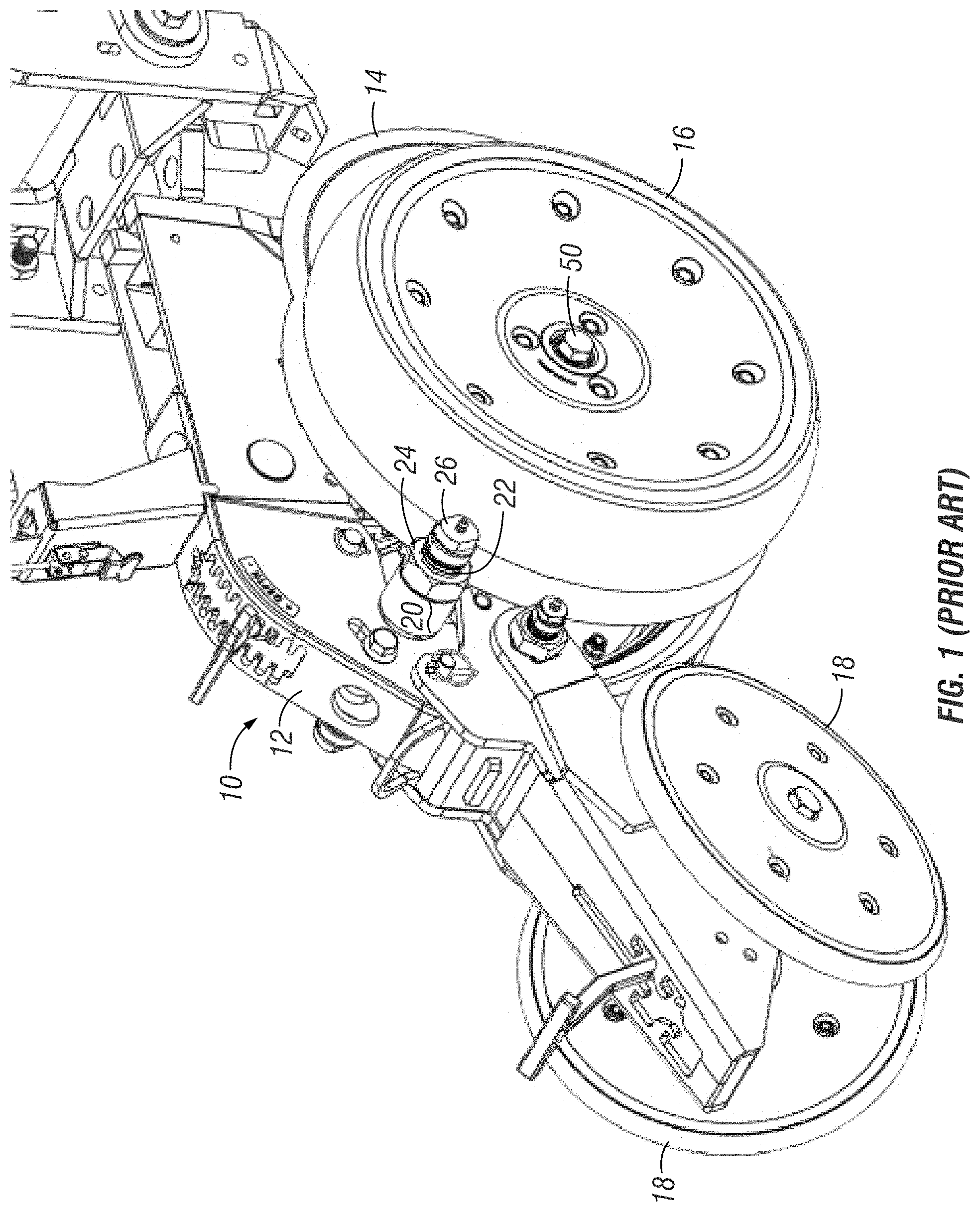
[0021] FIG. 1 is a perspective view of a row planting unit with a conventional pivotal mounting arm for the gauge wheels.
[0022] FIG. 2 is an exploded view of the planting unit and conventional gauge wheel pivot arm, as shown in FIG. 1, but with only one gauge wheel and arm shown for simplicity.
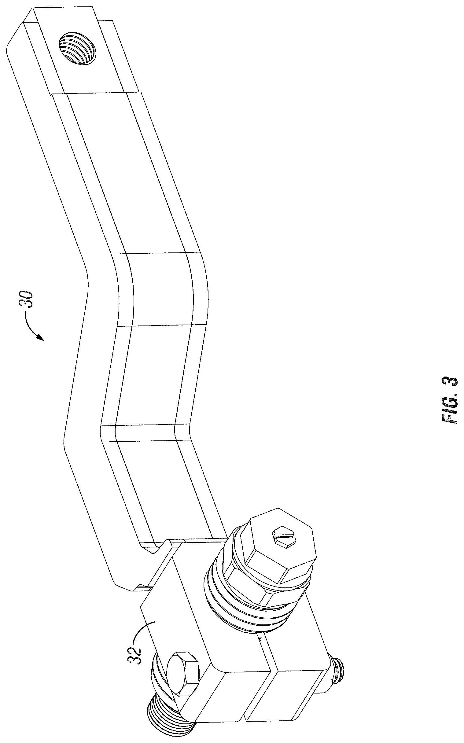
[0023] FIG. 3 is a perspective view of the gauge wheel pivot arm for lateral adjustment of the gauge wheel, according to the present invention.
[0024] FIG. 4 is an exploded view of the pivot arm shown in FIG. 3.
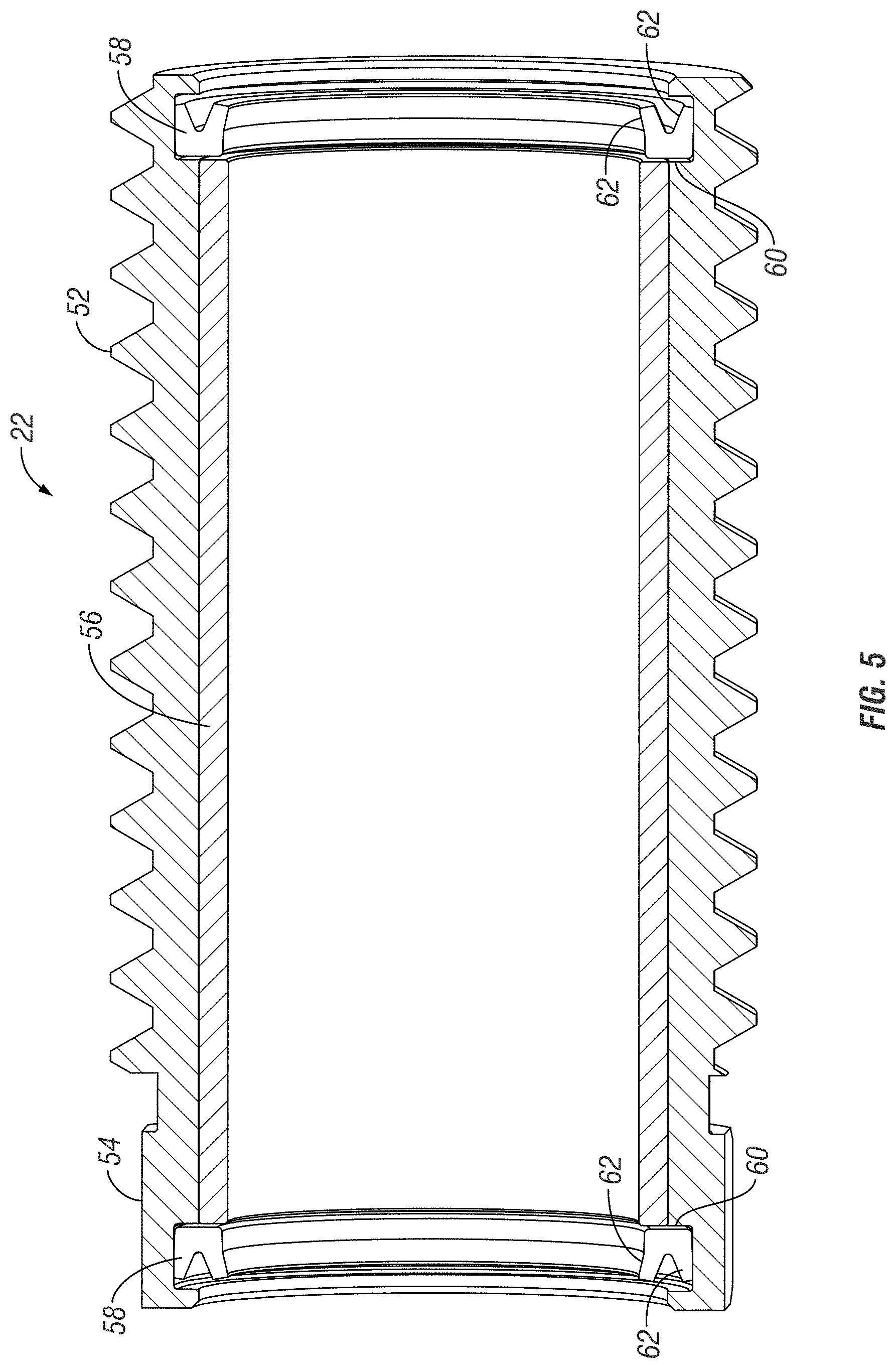
[0025] FIG. 5 is a sectional view of the threaded greaseless lateral adjustment bushing for the gauge wheel and pivot arm assembly.
DETAILED DESCRIPTION OF THE INVENTION
[0026] A conventional row planting unit 10 is shown in FIG. 1. The planting unit 10 includes a frame 12, a pair of furrow opening discs 14, a pair of gauge wheels 16, and a pair of closing wheels 18. Each gauge wheel 16 is mounted to the frame 12 using a mounting arm 20. In the prior art row planter unit 10 shown in FIG. 1, the mounting arm 20 has a threaded bore for receiving a threaded, greaseless adjustment bushing 22, which is fixed in position by a lock nut 24. A pivot bolt 26 extends through the bushing 22 to allow the gauge wheel 16 to pivot about the axis of the bolt 30, as the row planter unit 10 travels through the field during planting operations. FIG. 2 shows an exploded view of the planter unit 10 shown in FIG. 1. The structure and function of the planter unit 10 shown in FIGS. 1 and 2 is described in Applicant's U.S. Pat. No. 10,299,427 (issued May 28, 2019) incorporated herein by reference in its entirety.
[0027] The gauge wheel mounting arm 30 of the present invention is shown in FIGS. 3 and 4. The arm 30 replaces the arm 20 of the prior art row planter 10. The end of the arm 30 on which the gauge wheel 16 is mounted includes a head 32 with a threaded bore 34 extending therethrough. The head 32 is split by a slot 36 extending from the outer end or face of the head to the threaded bore 34, as best seen in FIG. 4, to form upper and lower split head ends 38, 40. A non-threaded hole 42 extends through the split ends 38, 40 in a direction transverse to the bore 34. A bolt 44 extends through the holes 42, with a nut 46 tightened on the threaded end of the bolt 44.
[0028] The inner end of the arm 30 has a hole 48 to receive a bolt 50 to mount the gauge wheel 16 to the arm 30.
[0029] The greaseless bushing 22 is described in Applicant's co-pending application Ser. No. 15/896,225, which is incorporated herein in its entirety by reference. A sectional view of the greaseless busing 22 used in the gauge wheel mounting arm 30, according to the present invention, is shown in FIG. 5. The bushing 22 has external threads 52 for threaded receipt in the bore 34 of the arm 30. The lock nut 24 of the prior art assembly (FIG. 2) is eliminated. The bushing 22 includes a hex end 54 for turning the bushing using a wrench or other tool. The bushing 22 is hollow, with an internal sleeve 56 made of a composite, non-metallic material. The low friction material of the sleeve 56 eliminates the need to grease the bushing 22. The inner sleeve 56 is pressed into the bushing 22, thereby allowing the assembly to pivot on the pivot bolt 26.
[0030] The bushing 22 includes a pair of annular seals 58, each of which are received in a groove 60 formed on the interior wall at each end of the bushing 22. Preferably, the seals 58 are a wiper-type seal, with a V-shaped cross-section, with leaves 62 facing outwardly toward the ends of the bushing 22. The seals 58 minimize or eliminate dust contamination within the bushings 22, thereby preventing lock up or freezing of the mounting arm 30.
[0031] The split end clamp style mounting arm 30 with the threaded bore 34 and the clamping bolt 44 has many advantages over the prior art gauge wheel mounting arms. For example, the arm 30 eliminates shim washers, thereby eliminating removal of the gauge wheel arms for adjustment. The arm 30 also eliminates the jam nut and set screw of prior art arms, such as those shown in application 2017/0202130 published on Jul. 20, 2017. Furthermore, the arm 30 eliminates extreme or excessive clamp pressure and arm movement, as in prior art clamp arms having a smooth bore. The combination of the split head 38, 40, the clamp bolt 44, and the threaded bore 34 for the threaded, greaseless, lateral adjust bushing assembly 22, allows for quick and easy infinite lateral adjustment of the gauge wheel 16 relative to the opening discs 14, simply by loosening the nut 46 and then turning the bushing assembly 22 using a tool on the hex head 54 of the bushing 22. Thus, the problems of the prior art are eliminated by the clamp arm 30, while allowing the gauge wheel 16 to be finely adjusted so as to maintain proper planting depth during operation of the row planting units 10.
[0032] The pivot bolt 26 has an inner threaded end received in a threaded shaft to allow adjustment of the camber of the gauge wheel, as described in U.S. Pat. No. 10,299,427.
[0033] The head 32 of the arm 30 is shown in the drawings to be somewhat rectangular, though it is understood that the head could be any shape, for example a round head with tabs or ears to receive the clamp bolt 44.
[0034] The invention has been shown and described above with the preferred embodiments, and it is understood that many modifications, substitutions, and additions may be made which are within the intended spirit and scope of the invention. From the foregoing, it can be seen that the present invention accomplishes at least all of its stated objectives.
* * * * *
D00000
D00001
D00002
D00003
D00004
D00005
XML
uspto.report is an independent third-party trademark research tool that is not affiliated, endorsed, or sponsored by the United States Patent and Trademark Office (USPTO) or any other governmental organization. The information provided by uspto.report is based on publicly available data at the time of writing and is intended for informational purposes only.
While we strive to provide accurate and up-to-date information, we do not guarantee the accuracy, completeness, reliability, or suitability of the information displayed on this site. The use of this site is at your own risk. Any reliance you place on such information is therefore strictly at your own risk.
All official trademark data, including owner information, should be verified by visiting the official USPTO website at www.uspto.gov. This site is not intended to replace professional legal advice and should not be used as a substitute for consulting with a legal professional who is knowledgeable about trademark law.