Adjustable Payload System For Small Geostationary (geo) Communication Satellites
Gedmark; John ; et al.
U.S. patent application number 16/699293 was filed with the patent office on 2020-06-04 for adjustable payload system for small geostationary (geo) communication satellites. The applicant listed for this patent is Astranis Space Technologies Corp.. Invention is credited to Karl Clausing, Siamak Ebadi, John Gedmark, Steven Joseph, Edward Keehr, Ryan McLinko, Braedon Salz, Ali Younis.
| Application Number | 20200177272 16/699293 |
| Document ID | / |
| Family ID | 70848528 |
| Filed Date | 2020-06-04 |


View All Diagrams
| United States Patent Application | 20200177272 |
| Kind Code | A1 |
| Gedmark; John ; et al. | June 4, 2020 |
ADJUSTABLE PAYLOAD SYSTEM FOR SMALL GEOSTATIONARY (GEO) COMMUNICATION SATELLITES
Abstract
An adjustable payload for small geostationary communication satellites is disclosed. In an example, a communication satellite includes a payload system having a software defined payload that is configured to provide communication services. The software defined payload includes a processor for providing at least one of gain control per transponder and carrier/sub-channel, channelization, channel routing, signal conditioning or equalization, spectrum analysis, interference detection, regenerative or modem processing, bandwidth flexibility, digital beamforming, digital pre-distortion or power amplifier linearization, for at least one user slice for a plurality of user terminals and at least one gateway slice for a gateway station. The software defined payload also includes an input side and an output side for each slice. Each input side includes an input filter and an analog-to-digital converter and each output side includes an output filter and a digital-to-analog converter. The payload system also includes antennas communicatively coupled to the software defined payload.
| Inventors: | Gedmark; John; (San Francisco, CA) ; Joseph; Steven; (San Francisco, CA) ; McLinko; Ryan; (San Francisco, CA) ; Salz; Braedon; (San Francisco, CA) ; Younis; Ali; (Washington, DC) ; Keehr; Edward; (Carlsbad, CA) ; Clausing; Karl; (San Carlos, CA) ; Ebadi; Siamak; (San Francisco, CA) | ||||||||||
| Applicant: |
|
||||||||||
|---|---|---|---|---|---|---|---|---|---|---|---|
| Family ID: | 70848528 | ||||||||||
| Appl. No.: | 16/699293 | ||||||||||
| Filed: | November 29, 2019 |
Related U.S. Patent Documents
| Application Number | Filing Date | Patent Number | ||
|---|---|---|---|---|
| 62772961 | Nov 29, 2018 | |||
| 62782024 | Dec 19, 2018 | |||
| Current U.S. Class: | 1/1 |
| Current CPC Class: | H04B 7/18513 20130101; H04B 7/18515 20130101; H04B 7/19 20130101; H04B 7/18528 20130101; H04B 7/2041 20130101 |
| International Class: | H04B 7/185 20060101 H04B007/185; H04B 7/19 20060101 H04B007/19; H04B 7/204 20060101 H04B007/204 |
Claims
1. A payload system for a communications satellite, the payload system including: a software defined radio ("SDR") configured to provide communication services, the SDR including a processor for providing at least one of gain control per transponder and carrier/sub-channel, channelization, channel routing, signal conditioning or equalization, spectrum analysis, interference detection, regenerative or modem processing, bandwidth flexibility, digital beamforming, digital pre-distortion or power amplifier linearization, for at least one user slice for a plurality of user terminals and at least one gateway slice for a gateway station; a front-end subsystem including an input side and an output side for each slice, each input side including an input filter and an analog-to-digital converter, each output side including an output filter and a digital-to-analog converter; and a plurality of antennas communicatively coupled to the front-end system.
2. The system of claim 1, wherein the front-end subsystem includes a radio frequency ("RF") receiver, the input side of the front-end subsystem additionally includes at least one of a down-converter or a low-noise amplifier ("LNA"), and the output side of the front-end subsystem additionally includes at least one of an up-converter or a power amplifier.
3. The system of claim 1, wherein the processor includes at least one of a field-programmable gate array ("FPGA"), a graphics processing unit ("GPU"), a central processing unit ("CPU"), or an application-specific integrated circuit ("ASIC").
4. The system of claim 1, wherein, for each of the slices, the input side and the output side are connected together by at least one of an orthomode transducer ("OMT") or a duplexer, which is connected to a respective antenna of the plurality of antennas.
5. The system of claim 1, wherein the processor is configured to change the at least one user slice for communication with the same or a different gateway station and change the at least one gateway slice for communication with at least some of the plurality of user terminals.
6. The system of claim 1, wherein the front-end subsystem includes between one and 256 input sides and between one and 256 output sides for the user and gateway slices.
7. The system of claim 1, wherein the processor in conjunction with the front-end subsystem is configured to independently or collaboratively tune a receive and a transmit frequency for each slice using at least one of tunable oscillators, adjustable filtering, adjustable sample rates, or digital up/down conversion.
8. The system of claim 1, wherein the processor is configured to provide an adjustable bandwidth for each of the slices.
9. The system of claim 1, wherein the processor is configured to: separate signals received from at least one of the slices into a plurality of narrowband channels; change a frequency and beam assignment for at least some of the channels based on a desired carrier plan, frequency plan, or network topology for the at least one slice; and combine the narrowband channels for the at least one slice.
10. The system of claim 1, wherein the processor is configured to provide for flexible beam shapes by routing a signal out to a desired number of the output slices, wherein the processor adjusts at least one of a phase or amplitude of the signal provided to each of the desired output slices to change a shape of a coverage area.
11. The system of claim 1, wherein the processor is configured to provide for dynamic beam hopping on the order of microseconds to hours or months by routing a signal out to a desired number of the output slices, wherein the processor adjusts at least one of a phase or an amplitude of the signal provided to each of the specified output slices to move a peak of a coverage area.
12. The system of claim 1, wherein the processor is configured to provide for noise removal by demodulating and decoding a received signal into a sequence of information bits before encoding and modulating for transmission.
13. The system of claim 1, wherein the processor is configured to provide for gateway spectrum compression by demodulating and decoding a received signal into a sequence of information bits and reconstructing the signal before encoding and modulating for transmission.
14. The system of claim 1, wherein the at least one user slice includes a first communication resource comprising a first range of frequencies having an electromagnetic polarization that is dedicated to carrying first communication data in a forward or reverse direction for at least some of the plurality of user terminals within a first defined geographic coverage area, and wherein the at least one gateway slice includes a second communication resource comprising a second range of frequencies having an electromagnetic polarization that is dedicated to carrying second communication data in a forward or reverse direction for the gateway station within a second defined geographic coverage area.
15. The system of claim 1, wherein the communications satellite is configured to at least one of: (i) test a new market; (ii) provide capacity for a gap in existing satellite coverage; (iii) provide a rapid response to at least one of a new or a changing condition on the ground; (iv) bridge traditional GEO capacity; (v) provide on-orbit redundancy and response to a failure in another satellite; (vi) provide bring-into-use ("BIU") services; (vii) operate in connection with other satellites to provide phased-in capacity; (viii) augment existing capacity; (ix) provide time-varying coverage; or (x) provide dedicated coverage for only one end customer.
16. The system of claim 1, wherein at least one of the SDR or the front-end subsystem is configured to provide at least one of: (i) a flexible carrier frequency; (ii) a flexible bandwidth; (iii) a flexible channelization and routing; (iv) noise removal; (v) a compressed gateway spectrum; (vi) signal conditioning via equalization or other digital processing techniques; (vii) gain control per transponder and per carrier/sub-channel; (viii) spectrum analysis; (ix) interference detection; (x) beam hopping; (xi) beam shaping; (xii) power amplifier linearization; or (xiii) digital pre-distortion.
17. The system of claim 1, wherein at least one of the SDR, the front-end subsystem, or the plurality of antennas is configured to at least one of: (i) communicate with a gateway via a millimeter-wave path or an optical path; (ii) provide flexible beam shapes; (iii) provide beam hopping between locations on the ground; (iv) provide a low-element phased array; (v) provide a high-element phased array; (vi) provide a flexible network topology; (vii) provide at least one intersatellite link to another satellite; (ix) provide a mesh network across satellites; (x) provide only transmission or only reception of data from at least one of a gateway or user terminals; (xi) enable gateway aggregation by co-locating gateways slices from multiple communications satellites on the communications satellite; or (xii) provide for communication with only the gateway station or the plurality of user terminals.
18. The system of claim 1, wherein the communications satellite is configured to provide at least one of frequent beam repointing, frequent orbital relocation, or repointing.
19. The system of claim 1, wherein the SDR and the front-end subsystem comprise a software defined payload that is configured for at least one of direct sampling, direct conversion, super-heterodyne with low intermediate frequency, super-heterodyne with high intermediate frequency, or three or more conversion stages comprising any mix of analog and digital conversion.
20. The system of claim 19, wherein software defined payload is configured to provide at least one of: (i) switching, combining, or splitting the at least one user slice; (ii) switching, combining, or splitting the at least one gateway slice; (iii) redundancy for the at least one user slice; (iv) redundancy for the at least one gateway slice; (v) leveraging of digital up/down conversion in data converters; (vi) implementation of fractional-N ("frac-N") phase locked loops to maximum frequency flexibility; or (vii) implementation of polyphase filter structures for resource efficient, ultra wideband signal processing.
Description
PRIORITY CLAIM
[0001] This application claims priority to and the benefit as a non-provisional application of U.S. Provisional Patent Application No. 62/772,961, filed Nov. 29, 2018 and U.S. Provisional Patent Application No. 62/782,024, filed Dec. 19, 2018, the entire contents of which are hereby incorporated by reference and relied upon.
BACKGROUND
[0002] Current commercial communication satellites are relatively large, expensive, and static in their operation. For example, many commercial satellites that are designed to provide voice and data communications weigh in excess of 15,000 pounds and cost over $300 million to develop, in addition to the $100+ million launch cost. For all the expense and weight, known commercial satellites generally only provide fixed services that are designed and provisioned years before the satellite is even launched. Most current commercial communication satellites are custom-built, meaning they are designed with carrier frequencies, bandwidths, beamwidths, modulation protocols, and a network topology specified by an operator. Oftentimes, it takes over five years to develop and launch commercial satellites as a result of this customization.
[0003] To recoup the significant development costs, commercial satellites are relatively large and typically designed to provide anywhere from 50 to 100 spot beams. With such a large capacity, it may take an operator over a decade to fully lease a commercial satellite. During this time, the unused capacity creates significant inefficiencies and increases the effective cost per megabyte ("Mb") of data transmitted. The large size and multiple licensees of commercial satellites also make the satellites difficult or impossible to reposition or repoint. Further, it is generally not economically practical for an operator to launch a second satellite to cover gaps in coverage or augment coverage in growing markets. It is also generally not practical for an operator to have on-orbit redundant commercial satellites given their significant expense. Large, expensive, inflexible commercial communication satellites are accordingly only deployed to cover areas that have large populations or entities willing to pay a significant amount of money for satellite coverage.
SUMMARY
[0004] The present disclosure describes a payload system that provides communication flexibility or adjustability for small geostationary ("GEO") communication satellites that use a software defined payload having a Software-Defined Radio ("SDR") system. The example communication satellite (illustrated in FIGS. 1 to 7) is configured to provide communication coverage between user terminals and one or more gateway stations. The flexibility of the payload system enables the communication satellite to change communication parameters post-deployment to adapt to changing conditions, end-user needs, or system requirements. The flexibility also enables the communication satellite to provide communication coverage for specified areas for defined periods of time, thereby providing an option for on-demand shared satellite coverage.
[0005] The example GEO communications satellite is configured to receive over-the-air updates that can change operational parameters and provide system flexibility. For instance, the GEO communications satellite disclosed herein may be configured to provide a flexible carrier frequency, flexible beamwidth, flexible bandwidth, flexible channelization and routing, flexible beam shapes, beam hopping, and flexible network topology via over-the-air updates. The example GEO communications satellite may adjust signal amplitude and/or phase using low-element phased arrays and/or high-element phased arrays for forming beam shapes and beam hopping. In contrast, known commercial GEO satellites are generally static by design and do not permit or are incapable of adjustments in carrier frequency, beamwidth, channelization/routing, beam shapes, beam hopping, and/or network topology.
[0006] Additionally, the example GEO communications satellite disclosed herein may be configured to communicate with gateway stations at higher frequencies compared to user links over, for example, millimeter-wave and/or optical links to provide more bandwidth for users. The GEO communications satellite disclosed herein may be configured with large flexible aperture antennas, thereby improving data rates compared to known satellite systems that generally have smaller (but more numerous) antennas. In some embodiments, the example GEO communications satellite may have a single large flexible aperture and be provisioned in a network with other similar satellites with their own large flexible apertures. This configuration provides a data rate advantage over known commercial satellites, which are limited to a number of small apertures as a result of satellite housing physical spacing limitations.
[0007] The example SDR system provided on the GEO communications satellite disclosed herein enables noise removal, use of a compressed gateway spectrum, and/or equalization to improve data throughput and overall system efficiency. Known commercial systems typically do not have these features since they do not possess digital signal processing capabilities. These improvements result in increased system capacity and a lower cost of data transmission.
[0008] In some embodiments, the example GEO communications satellite is configured to operate with similar satellites to provide interlaced beams. Further, the satellites may use intersatellite linking to form mesh networks. The intersatellite linking also enables certain satellites to be provisioned as transmission-only or reception-only, and/or provide for gateway aggregation.
[0009] The example GEO communications satellite is configured to have a smaller size compared to commercial satellites. For example, the GEO communications satellite disclosed herein may have a size that is 1/10 the size of a traditional communication satellite. This small size enables the disclosed GEO communications satellite to be frequently repointed and/or relocated over its life, with less fuel being required to perform the maneuvers. The smaller size and flexibility of the GEO communications satellite also enables it to be developed quickly (usually within 18 months from commissioning) and delivered to orbit within a shared rocket payload. By comparison, known commercial satellites may require five years for development to accommodate all the customization required for a dedicated rocket launch, which can take time scheduling. In some embodiments, the example GEO communications satellite disclosed herein provides a small capacity for a low cost, which enables many uses that are not practical for known commercial satellite systems.
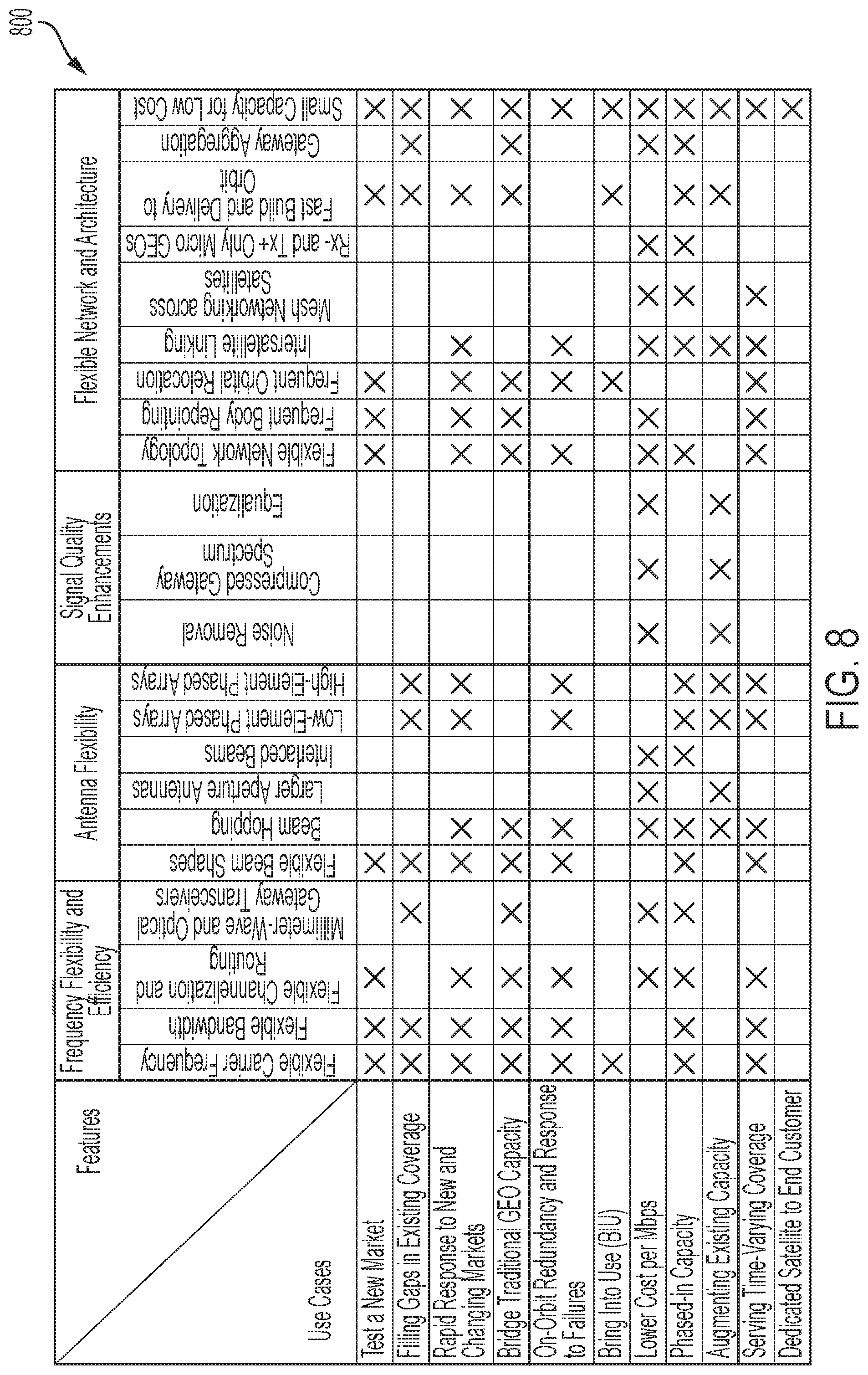
[0010] Chart 800 of FIG. 8 shows how the above-discussed features (discussed in connection with FIGS. 9 to 54) of the example GEO communications satellite can be employed over one or more uses, which are described further in connection with FIGS. 55 to 65. Any one feature configured on the disclosed GEO communications satellite may enable any one of the corresponding uses described herein. Additionally, it should be appreciated that any version of the example GEO communications satellite disclosed herein may be deployed with any number of features based on mission specifications.
[0011] The example GEO communications satellite disclosed herein has a lower cost per Mb/s compared to traditional satellites (see FIG. 61), which enables it to be used in more economically-sensitive locations and/or missions. In addition, the example GEO communications satellite enables an operator to test new markets (See FIG. 55) by deploying a small satellite to test a hypothesis or business case without having to invest hundreds of millions of dollars in a large commercial satellite. The above features also enable operators to be responsive to changing ground or aero conditions (see FIG. 57) by providing rapidly deployable systems and provide for bring-into-use ("BIU") applications (see FIG. 60) when new frequency spectrums become available. The example GEO communications satellite may provide an economical means to provide relatively small but important amounts of coverage by filling gaps in existing coverage (see FIG. 56), bridging traditional GEO capacity (see FIG. 58), phasing-in capacity over time based on demand (see FIG. 62), and/or augmenting existing coverage (see FIG. 63).
[0012] The example GEO communications satellite also may be provided as a redundant system or spare (see FIG. 59). This redundancy enables the example GEO communications satellite to provide an almost real-time response to fill in for satellites that go offline or experience failures. Moreover, the example GEO communications satellite may be configured to repoint or reposition itself to provide time-varying coverage (see FIG. 64). For example, the example GEO communications satellite may repoint to follow primetime bandwidth usage through different time zones, provide seasonal coverage based on demand from users or customers, or provide capacity in response to terrestrial outages during and after natural disasters. Additionally, the example GEO communications satellite may be dedicated entirely to a single end customer (See FIG. 65). The small cost of the GEO communications satellite makes it economically feasible for a single customer to have a satellite that is provisioned exactly for their requirements and pointed exactly to where coverage is needed.
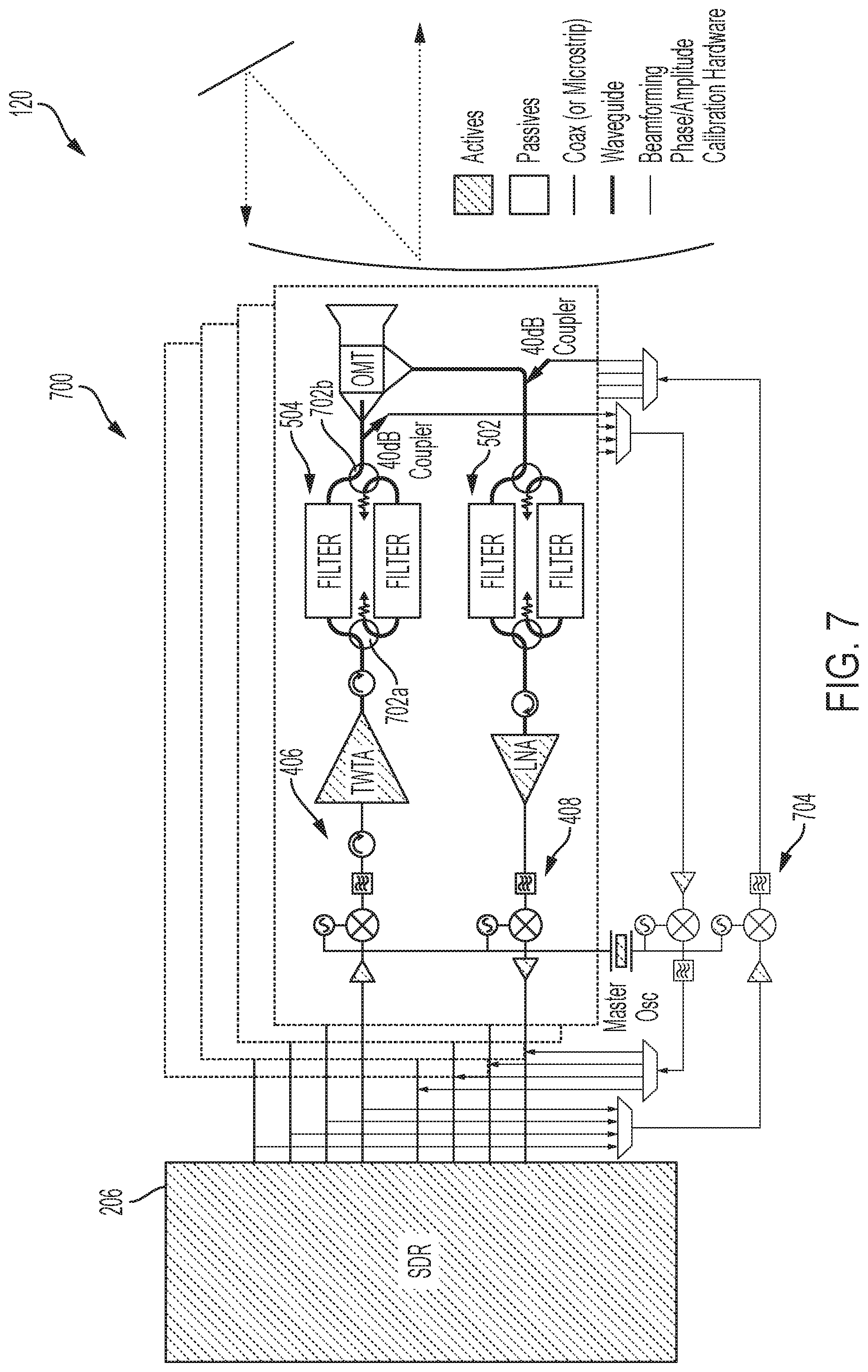
[0013] The following disclosure begins with a description of the example communications satellite, including a description of the SDR, antennas, and passive components. The disclosure then discusses satellite features that are made possible by the disclosed satellite system. The disclosure concludes by discussing novel uses of the example GEO communications satellite that are enabled by one or more combinations of the disclosed system features.
[0014] The example payload system (e.g., the software defined payload) disclosed herein includes an SDR that is communicatively coupled to one or more antennas via a front-end subsystem. The SDR includes a processor, which may comprise any field-programmable gate array ("FPGA"), graphics processing unit ("GPU"), central processing unit ("CPU"), an application-specific integrated circuit ("ASIC"), etc. The example payload system described herein includes an antenna system, front-end passive components, an adjustable transmitter and receiver, a master reference oscillator, and the SDR. In some embodiments, the payload system may include one or more filters, low-noise amplifiers ("LNAs"), down-converters, and analog-to-digital converters ("ADCs") on a receiver side, and one or more filters, RF power amplifiers (e.g., traveling-wave tube amplifiers ("TWTAs")), up-converters, and digital-to-analog converters ("DACs") on the transmitter side. At least some of the amplifiers, filters, and/or converters of the front-end system are adjustable components that permit parameter changes after deployment. In addition, the SDR includes adjustable parameters that provide further post-deployment flexibility to the communication system.
[0015] In some embodiments, the front-end subsystem may be modular, enabling certain customization/provisioning per customer requirements with minimal tuning of the SDR for compatibility. The front-end subsystem may be implemented by software stored in a memory device of the software defined payload. Altogether, the example SDR and front-end subsystem of the are configured to enable a flexible carrier frequency, flexible bandwidth, flexible channelization and routing, adjustable RF transmitted and received polarization, compatibility with millimeter-wave and optical gateway transceivers, flexible beam shapes, beam hopping, interlaced beams, use of large flexible aperture antennas, use of low-element/high-element phased arrays, noise removal and equalization, flexibility for a compressed gateway spectrum, flexibility for different network topologies, capability for frequent body repointing and/or orbital relocation, and/or intersatellite linking for mesh networking, Rx and Tx dedicated systems, and gateway aggregation, any of which may be updated or provisioned post-deployment in over-the-air updates. The above-features of the example communication satellite system enables new markets to be tested, gaps in existing satellite coverage to be filled, rapid response to new and changing markets, bridging traditional GEO-satellite capacity, on-orbit redundancy and response to failures, phased-in capacity, augmentation of existing capacity, time-varying coverage service, dedication to a particular customer, fast development and deployment for bring-into-use ("BIU") circumstances, and lower costs per Mbps.
[0016] In an example embodiment, a payload system for a communications satellite includes a SDR configured to provide communication services. The SDR includes a processor configured to provide at least one of gain control, channelization, beamforming, and channel routing for at least one user slice or beam for a plurality of user terminals and at least one gateway slice or beam for a gateway station. The example payload system includes a front-end subsystem including an input side and an output side for each slice. Each input side includes an input filter, a down-converter, and an analog-to-digital converter, and each output side includes an output filter, an up-converter, and a digital-to-analog converter. The payload system further includes a plurality of antennas communicatively coupled to the front-end system.
[0017] The example down-converter and the up-converter of each slice are adjustable to enable a receive frequency and transmit frequency to be tunable. In addition, the processor is configured to provide an adjustable bandwidth for each of the slices. The processor may also be configured to separate signals received from at least some of the slices into a plurality of narrowband channels, change a frequency and beam assignment for at least some of the channels based on a desired network topology for at least one of the slices, and combine the narrowband channels for the at least one slice. The processor may further provide for flexible beam shapes by routing a single received signal out to a desired number of the output slices, where the processor adjusts a phase and/or amplitude of a signal provided to each of the desired output slices to change a shape of a coverage area. Additionally or alternatively, the processor is configured to provide for flexible beam hopping by routing a single received signal out to a desired number of the output slices, where the processor adjusts a phase of a signal provided to each of the desired output slices to move a peak of a coverage area. Moreover, the processor is configured to provide for noise removal by demodulating and decoding a received signal into a digital stream (e.g., a sequence of information bits) before encoding and modulating for transmission. Also, the processor may be configured to provide for signal equalization by equalizing a transmission signal before noise is added and/or configured to provide for gateway spectrum compression by demodulating and decoding a received signal into a binary stream before encoding and modulating for transmission.
[0018] The advantages discussed herein may be found in one, or some, and perhaps not all of the embodiments disclosed herein. Additional features and advantages are described herein, and will be apparent from the following Detailed Description and the figures.
BRIEF DESCRIPTION OF THE FIGURES
[0019] FIG. 1 shows a diagram of an example communications satellite, according to an embodiment of the present disclosure.
[0020] FIG. 2 shows an example diagram of an SDR of the example communications satellite of FIG. 1, according to an example embodiment of the present disclosure.
[0021] FIG. 3 shows an example front-end system of the communications satellite of FIG. 1 connected to the SDR of FIG. 2, according to an example embodiment of the present disclosure.
[0022] FIG. 4 shows a diagram of an example payload communications system of the communication satellite of FIG. 1, according to an example embodiment of the present disclosure.
[0023] FIGS. 5 to 7 show diagrams of different embodiments of the example payload communications system of FIG. 4, according to example embodiments of the present disclosure.
[0024] FIG. 8 shows a diagram of an example chart that shows a relation between features of the example communications satellite, including the SDR of FIG. 2 and corresponding use cases supported by the features, according to example embodiments of the present disclosure.
[0025] FIGS. 9 and 10 show diagrams that compare known satellite systems and the example GEO communications satellite of FIG. 1 regarding carrier frequency adjustability, according to example embodiments of the present disclosure.
[0026] FIGS. 11 to 14B show diagrams that compare known satellite systems and the example GEO communications satellite of FIG. 1 regarding bandwidth adjustability, according to example embodiments of the present disclosure.
[0027] FIGS. 15 and 16 show diagrams that compare known satellite systems and the example GEO communications satellite of FIG. 1 regarding channelization and routing flexibility, according to an example embodiment of the present disclosure.
[0028] FIGS. 17 and 18 show diagrams related to the communications satellite, including the SDR of FIG. 2 being configured to operate with millimeter-wave and optical gateway transceivers, according to example embodiments of the present disclosure.
[0029] FIGS. 19 to 21 show diagrams that compare known satellite systems and the example GEO communications satellite of FIG. 1 regarding beam shape flexibility, according to example embodiments of the present disclosure.
[0030] FIGS. 22, 23A, and 23B show diagrams that compare known satellite systems and the example GEO communications satellite of FIG. 1 regarding beam hopping capability, according to example embodiments of the present disclosure.
[0031] FIGS. 24, 25A, and 25B show diagrams that compare known satellite systems and the example GEO communications satellite of FIG. 1 regarding the use of large flexible aperture antennas, according to an example embodiment of the present disclosure.
[0032] FIGS. 26 and 27 show diagrams that compare known satellite systems and the example GEO communications satellite of FIG. 1 regarding the use of interlaced beams, according to an example embodiment of the present disclosure.
[0033] FIGS. 28 to 30 show diagrams that compare known satellite systems and the example GEO communications satellite of FIG. 1 regarding the use of low-element and high-element phased arrays, according to an example embodiment of the present disclosure.
[0034] FIGS. 31 to 33 show diagrams that compare known satellite systems and the example GEO communications satellite of FIG. 1 regarding noise removal capability, according to example embodiments of the present disclosure.
[0035] FIGS. 34 and 35 show diagrams that compare known satellite systems and the example GEO communications satellite of FIG. 1 regarding compressed gateway spectrum, according to example embodiments of the present disclosure.
[0036] FIGS. 36 and 37 show diagrams that compare known satellite systems and the example GEO communications satellite of FIG. 1 regarding equalization capability, according to example embodiments of the present disclosure.
[0037] FIGS. 38 to 41 show diagrams that compare known satellite systems and the example GEO communications satellite of FIG. 1 regarding network topology flexibility, according to example embodiments of the present disclosure.
[0038] FIG. 42 shows a diagram of an example operating environment in which communication satellites having the SDR of FIG. 2 operate together and are co-located within a single GEO orbital slot.
[0039] FIGS. 43 and 44 show diagrams related to mesh networking of the example payload communications system of FIG. 4, according to example embodiments of the present disclosure.
[0040] FIGS. 45 to 48 show diagrams related to specially configured satellites, according to example embodiments of the present disclosure.
[0041] FIGS. 49 and 50 show diagrams related to frequent body repointing features of the communications satellite, according to an example embodiment of the present disclosure.
[0042] FIGS. 51 and 52 show diagrams related to frequent orbital relocation features of the communications satellite, according to an example embodiment of the present disclosure.
[0043] FIGS. 53 and 54 show diagrams related to how a smaller capacity of the example GEO communications satellite of FIG. 1 enables lower cost for the same coverage area on the ground or air, according to an example embodiment of the present disclosure.
[0044] FIGS. 55 to 65 show diagrams related to unique uses of the example GEO communications satellite of FIG. 1 that cannot be economically performed by conventional satellites, according to example embodiments of the present disclosure.
DETAILED DESCRIPTION
[0045] The present disclosure relates in general to a flexible payload system for small communication satellites. The example payload system includes an SDR and a front-end system. The SDR includes a processor, such as a field-programmable gate array ("FPGA") that implements communication hardware components, such as mixers, filters, amplifiers, modulators/demodulators, detectors, etc. as software. The software is specified by one or more instructions or gate configurations stored in a memory device (such as a reprogrammable memory device) that is accessible by a processor of the SDR.
[0046] The SDR may also include analog components for signal filtering, amplification, up-conversion, and/or down-conversion. The example SDR may be configured to provide for modulation and demodulation of any waveform, decoding and encoding of any waveform, channelization and routing, equalization, distortion compensation for channel effects, and compensation for RF front end impairments. It should be appreciated that the processor of the SDR is not limited to an FPGA and may include any ASIC, GPU, CPU, microcontroller, microprocessor, etc.
[0047] Reference is made herein to specific hardware configurations of an example communications satellite. Reference is also made herein to capabilities of an SDR. It should be appreciated that the example GEO communications satellite is not limited to the hardware configurations disclosed herein and may include alternative configurations and/or components configured to perform the same operation or provide the same result. Further, some of the hardware configurations may instead be implemented internally by a processor of the SDR, through, for example, digital processing. It should also be appreciated that in some embodiments, operations performed by the processor may instead or additionally be performed by hardware. The disclosure provided herein discusses example embodiments regarding compositions of the example communications satellite.
[0048] Reference is also made throughout to features and uses of the example communications satellite. It should be appreciated that a GEO communications satellite may be configured to perform all or a subset of the described uses based, for example, on provisioning. Further, it should be appreciated that the GEO communications satellite may include all or a subset of the described features, which enable the different described uses to be performed.
GEO Communications Satellite Embodiment
[0049] FIG. 1 shows a diagram of an example GEO communications satellite 100, according to an example embodiment. The example satellite 100 is configured to provide communication services to aero or ground locations using a payload communications system 120. The satellite 100 transmits and receives wireless signals using one or more antennas 103. The satellite 100 may include a first reflector 102 and a second reflector 104 to direct the signals to the one or more feed antennas 103.
[0050] Together with the payload communications system 120, the example GEO communications satellite 100 is configured to provide SDR services to specified aero or ground locations. The SDR services enable communication parameters to be changed as desired while the satellite 100 is in orbit, including providing a flexible carrier frequency, flexible bandwidth, flexible channelization and routing, compatibility with millimeter-wave and optical gateway transceivers, flexible beam shapes, beam hopping, interlaced beams, use of large flexible aperture antennas, use of low-element/high-element phased arrays, noise removal and equalization, flexibility for a compressed gateway spectrum, flexibility for different network topologies, capability for frequent body repointing and/or orbital relocation, and/or intersatellite linking for mesh networking, Rx and Tx dedicated systems, and gateway aggregation, any of which may be updated or provisioned post-deployment in over-the-air updates.
[0051] The example satellite 100 includes a structure 108 configured to enclose and/or provide structural support to the feed antennas 103, reflectors 102 and 104, the payload communications system 120, battery, and other subsystems disclosed herein. The satellite 100 is powered by at least one on-board battery, which is recharged via solar arrays 110 and 112. The satellite may include an electric propulsion subsystem and/or a monopropellant subsystem for deployment, repositioning, or re-orientation.
[0052] The illustrated satellite 100 is relatively small compared to known commercial communication satellites. In an embodiment, the satellite 100 has a height, length, and depth of 1 meter ("m"), thus having a volume of 1 m.sup.3. In other embodiments, the satellite 100 may be larger or smaller. For example, the satellite may have a volume as small as 0.65 m.sup.3 or a volume as large as 10 m.sup.3.
Payload System Embodiment
[0053] FIG. 4 shows a diagram of the example payload communications system 120 of FIG. 1, according to an example embodiment of the present disclosure. The example system 120 is communicatively coupled to the feed antennas 103 via one or more transmitting (e.g., TX) and receiving (e.g., RX) lines and signal multiplexers. In the illustrated embodiment, the payload communications system 120 includes eight transmission lines (e.g., eight intermediate frequency output ports with a 1.0 to 6.0 GHz capability) and eight receiving lines (e.g., eight intermediate frequency input ports with a 0.5 to 5.5 GHz capability), thus creating eight paths. In other embodiments, the payload communications system 120 may include fewer or additional lines.
[0054] The example payload communications system 120 includes an SDR 206 that is electrically and communicatively coupled to the transmitting and receiving lines. FIG. 2 shows a diagram of the SDR 206, according to an example embodiment of the present disclosure. As shown in FIGS. 2 and 4, the example SDR 206 is coupled to an intermediate frequency ("IF") board 202, which is configured to convert signals for transmission or reception over the transmitting and receiving lines. The payload communications system 120 also includes a digital board 204 that is configured to house the SDR 206 for processing signals for transmission. In the illustrated example, the IF board 202 includes amplifiers, filters, and up/down converters while the digital board 204 includes digital-to-analog converters ("DACs"), analog-to-digital converters ("ADCs"), and an FPGA processor 302, which collectively comprise the SDR 206. In other examples, the IF board 202 and the digital board 204 may be combined or components from the boards 202 and 204 may be arranged differently. For example, in some embodiments, the DAC/ADCs may instead be located on the IF board 202. Alternatively, in some examples, the IF board 202 functionality may be included in upconverters 406 and downconverters 408 (shown in FIG. 3).
[0055] The example SDR 206 is configured to process signals received on input ports or receiving lines for transmission via the output ports or transmission lines. As shown in FIG. 2, the SDR 206 includes, in order from reception to transmission, interfaces configured to connect to the ADCs, gain control, IQ/DC compensation, channelization, equalization, beamforming processing, and channel routing. In addition, for transmission, the SDR 206 includes beamforming processing, equalization, channelization, IQ/DC compensation, gain control, and interfaces configured to connect to the DACs.
[0056] The channel routing of the SDR 206 may provide routing at one or many different network levels. For example, the channel routing may route signals at a physical level, where signals having a certain specified carrier frequency are routed to another channel. The channel routing may also provide routing at the network or hardware level, where data packets may be routed to other channels based on destination Internet Protocol ("IP") address, media access control ("MAC") address, domain address, etc.
[0057] In the illustrated example, the SDR 206 is configured for three user slices (shown as User RED, User GRN, and User BLU) and one gateway slice (shown as GW RED, GW GRN, and GW BLU). As disclosed herein, each slice includes a communication resource comprising a range of frequencies having an electromagnetic polarization that is dedicated to carrying communication data in a forward or reverse direction for at least some of the plurality of user terminals and/or gateway stations that are located within a defined geographic coverage area. Each user slice communicates with a distinct gateway slice while the gateway slice combines/splits inputs/outputs to/from the three different user slices. Each slice includes a transmitting/output port and a receiving/input port, as shown in FIGS. 5 to 7. For reception, in the illustrated embodiment, the RF/IF front end includes a transmission rejection filter (e.g., an LNA filter with isolator), and a down-converter. For transmission, in the illustrated embodiment, each slice includes an up-converter, TWTA, and a reception band noise rejection filter. In other examples, the SDR 206 is configured to support additional or fewer slices. For example, the SDR 206 shown in FIG. 6 supports five different slices. In other examples, the SDR 206 may support anywhere between one and 256 user and/or gateway slices on both the transmission and reception sides.
[0058] In the illustrated example, each input/output port corresponds to a channel, which may be divided into sub-channels (e.g., 2 MHz sub-channels). In addition, the SDR 206 of FIG. 2 may be configured to provide equalization for the analog-RF front end and automatic gain control with, for example, 40 to 45 dB of dynamic range). Further, the SDR 206 of FIG. 2 may be configured to provide 5 GHz of frequency flexibility with 1 GHz, or more, of instantaneous bandwidth per port.
[0059] The SDR 206 (shown in FIG. 4) also includes a payload power board 208 and an SDR power board 210. The payload power board 208 is configured to isolate a battery power supply from the payload communications system 120 and establish a single point of ground for the SDR 206. The payload power board 208 may convert a 28 volt power supply to 5.5 volts for the SDR 206 and other components on the boards 202 and 204. The example SDR power board 210 may include a buck converter configured to provide an adjustable voltage of 0.9 volts to 3.3 volts for the SDR 206 and/or other components on the boards 202 and 204.
[0060] FIG. 3 shows a diagram of a processor 302 (e.g., an FPGA) of the SDR 206 that is communicatively coupled to one or more DACs 402 and one or more ADCs 404 for each input and output port. On the input side, the ADC 404, for each input or receiving line, is connected to a down-converter 406. On the output side, the DAC 202, for each output or transmission line, is connected to an up-converter 408. In the illustrated embodiment, the ADC 404 and down-converter 406 provide for two separate slices, shown as channel CH0 and channel CH1. In addition, the DAC 402 and the up-converter 408 provide for two separate slices, shown as channel CH0 and channel CH1. In other embodiments, only one channel may be provided, or more than two slices may be supported (e.g., four slices).
[0061] In the illustrated example, the processor 302 is communicatively coupled to eight ADCs 404 and eight DACs 402. The eight input and output connections provided by the ADCs 404 and the DACs 402 may correspond to, for example, the 8 user/gateway inputs/outputs shown in FIG. 2 of the SDR 206.
[0062] The example ADCs 404 may have a sampling rate between 1000 MS/s and 20 GS/s. In addition, the ADCs 404 may have an input bandwidth between 500 MHz and 10 GHz, for example, around 5 GHz with 0.5 dB of ripple or 9 GHz with 3 dB of ripple. Further, the ADCs 404 may have a resolution between 9 bits and 20 bits, for example, between 10 and 14 bit with a resolution with +/-0.5b INL/DNL.
[0063] The example DACs 402 may have a sampling rate between 0.5 GS/s and 20.0 GS/s. The example DACs 402 may also be configured to have sufficiently high spurious-free dynamic range ("SFDR") as to meet International Telecommunication Union ("ITU") emissions requirements. For example, the DACs 402 may provide 60 dB SFDR at -2.4 dBm output power and have a resolution between 9 bits and 20 bits, for example, around 16 bits with a power ratio of -74 dBc SFDR at -7 dBFS output. Further, the DACs 402 may be configured to provide internal interpolation of at least one of 1.times., 2.times., 4.times., or 8.times..
[0064] The example down-converter 406 is configured to convert a received signal to a lower frequency for digitization by the ADC 404. The illustrated down-converter 406 of FIG. 3 includes a variable gain IF amplifier 410 configured to reduce the dynamic range of a received signal (e.g., gain control). The down-converter 406 may be configured to provide for IQ demodulation to retain phase information after a translation to a baseband signal. The down-converter 406 includes a fractional phase-locked loop ("PLL") configured to tune to a center frequency of a desired channel. The down-converter 406 also includes lowpass filters to remove adjacent channels. The PLL of the down-converter 406 may be configured to provide IF frequencies from 0.5 to 6.5 GHz with phase noise under -110 dBc/Hz at 100 Hz and an output power of 3 dBm.
[0065] The example up-converter 408 is configured to process I and Q signals from the DAC 402, which can be a dual channel DAC or of any other architecture. The up-converter 408 includes low pass filters to remove DAC images and an IQ modulator to inject phase information into the IF carrier signal. Fractional PLLs of the up-converter 408 are configured to tune to a center frequency of a desired channel. The up-converter 408 further includes a variable attenuator 412 (capable of providing up to 12 dB of programmable attenuation) for high backoff when increased linearity is desired. In some embodiments, the attenuator 412 includes the TWTA of FIGS. 5 to 7. The PLL of the up-converter 408 may be configured to provide IF frequencies from 0.5 to 6.5 GHz with phase noise under -110 dBc/Hz at 100 Hz and an output power of 3 dBm. The up-converter 408 may provide 500 MHz single-sided bandwidth and have a 0.1 dB gain imbalance and 1.5 degree of phase imbalance.
[0066] The down-converter 406 and/or the up-converter 408 enable the SDR 206 to improve rejection of adjacent channels, compensate for IQ imbalance, compensate for mixer local oscillator ("LO") feedthrough, split a signal into many 2 MHz subcarriers, and equalize linear distortion in the IF board 202 (e.g., a front-end) and uplink channel. The PLL of the down-converter 406 can be configured to provide IF frequencies from 0.5 to 6.5 GHz with phase noise under -110 dBc/Hz at 100 Hz and an output power of 3 dBm. The down-converter 406 may provide at least 500 MHz single-sided bandwidth with about 42 dB of programmable gain with a 0.1 dB gain imbalance and 1.5 degree of phase imbalance.
[0067] FIGS. 5 to 7 show diagrams of different embodiments of example payload communications systems 500, 600, and 700 (e.g., a software defined payload), according to example embodiments of the present disclosure. The example SDR 206 is configured to enable any of the embodiments of FIGS. 5 to 7 to be used based on customer or end-user specifications without significant modification or tuning. In other words, the embodiments of example payload communications systems 500, 600, and 700 are modular and may replace each other for the payload communications system 120 described in conjunction with FIGS. 1 to 4. As described below, each of the embodiments provide different capabilities.
[0068] FIG. 5 shows slices labeled as red, green, blue, and gateway. The labeling corresponds to the labeling of the inputs/outputs of the SDR 206 shown in FIG. 2. For example, the red slice of FIG. 5 corresponds to the "User RED" and "GW RED" input/output of the SDR 206 shown in FIG. 2. The gateway slice is combined/split with the inputs/outputs of the three different user SDR slices (green, blue, and red) via a duplex antenna configuration. In other embodiments, at least one slice may be dedicated for signals to/from the gateway via a dedicated duplex antenna.
[0069] In the illustrated example, each user slice includes an input line/port and output line/port, which are connected at a duplexer ("DPLX") or orthomode transducer ("OMT"). The choice may depend on the antenna configuration implemented. An input line 502 of a slice includes an input filter, such as a transmission band rejection filter and a LNA. The filter may be configured to pass frequencies between 27 GHz and 30 GHz or any other range depending on the operating frequency bands of the mission. The input line 502 further includes the down-converter 408. An output line 504 of the slice includes a reception band noise rejection filter, a TWTA, and the up-converter 406.
[0070] In the illustrated example of FIG. 5, shaded components, such as the TWTA, LNA, the up-converter 406, and the down-converter 408 are active and may be adjustable by the SDR 206, which provides a front-end subsystem of the payload communications system 500 flexibility disclosed herein. Specifically, the TWTA, LNA, amplifiers, multipliers, LOs, PLLs and/or LPFs of the up-converter 406 and the down-converter 408 are active components. The example configuration illustrated in FIG. 5 may be configured to provide one or more fixed beams, including, for example, regional beams or high-throughput satellite ("HTS") spot beams. The adjustability of the front-end subsystem of the payload communications system 500 (in addition to the SDR 206) enables flexibility of the features discussed below.
[0071] The example front-end subsystem of the payload communications system 600 of FIG. 6 includes similar input lines 502, output lines 504, down-converters 408, and up-converters 406 as the front-end subsystem 500 of FIG. 5. However in the example of FIG. 6, the system 600 is configured to provide six user slices and one gateway slice. In this example, the six user slices are configured to provide beams for user terminals while the gateway slice is configured to communication with a gateway station. Similar to the system 500 of FIG. 5, the system 600 of FIG. 6 may be configured to provide one or more fixed beams, including, for example, regional beams or HTS spot beams. The adjustability of the front-end of the payload communications system 600 (in addition to the SDR 206) enables flexibility of the features discussed below.
[0072] The example front-end subsystem of the payload communications system 700 of FIG. 7 includes a switch (shown as switch 702a/702b) between two filters for each input line 502 and output line 504. On the transmission side, a first filter may pass frequencies between 10.5 and 11.5 GHz, while the second filter passes signals between 11.0 and 13 GHz. In other examples, the switch 702 may be removed and the input line 502 and the output line 504 may each include a single filter.
[0073] The example front-end subsystem of the payload communications system 700 of FIG. 7 includes a beamforming calibration network 704. The network 704 is configured to transmit and measure signals including, for example, different direct sequence spread spectrum pseudonoise ("PN") sequence on each transmit chain. The network 704 may be configured to receive a different sequence on each receive chain for beamforming calibration. The beamforming calibration may enable flexible beam shaping and/or beam hopping in addition to providing one or more fixed beams, including, for example, regional beams or HTS spot beams. The adjustability of the front-end of the payload communications system 700 (in addition to the SDR 206) also enables flexibility of the features discussed below.
[0074] In either of the embodiments of FIGS. 5 to 7, the example SDR 206 may be configured with a regenerative configuration for increased compute capabilities. The increased capabilities include, for example, noise removal and a compressed gateway spectrum, as described below in more detail.
Features of the Example Communications Satellite
[0075] As described above in connection with FIGS. 1 to 7, the example GEO communications satellite 100 with the SDR 206, provides for feature flexibility and adaptability that enables a multitude of different uses. FIG. 8 shows a diagram of an example chart 800 that illustrates a relation between features of the example GEO communications satellite 100 via the SDR 206 and corresponding uses supported by the features. The example features provided by the GEO communications satellite 100 comprise frequency flexibility and efficiency, antenna flexibility, signal quality enhancements, and flexibility based on a network or architecture. Frequency flexibility and efficiency includes flexible carrier frequencies, flexible bandwidth, flexible channelization and routing, and/or the use of millimeter-wave and optical gateway transceivers. Antenna flexibility includes flexible beam shapes, beam hopping, interlaced beams, and/or the use of large flexible aperture antennas, low-element phased arrays, and high-element phased arrays. Signal quality enhancements include noise removal, compressed gateway spectrum, and/or equalization. Flexibility based on a network or architecture includes a flexible network topology, frequent body repointing, frequent orbital relocation, inter-satellite linking, mesh networking across satellites, Rx- and Tx-only satellite systems, fast build and delivery to orbit capabilities, gateway aggregation, and/or small capacity for low cost capabilities.
[0076] The example chart 800 of FIG. 8 shows how each of the mentioned features relate to different uses, including testing for a new market, filing in gaps in existing coverage, rapid response to new and changing markets, bridging traditional GEO capacity, on-orbit redundancy and response to failures, bring into use ("BIU"), lower cost per Mbps, phased-in capacity, augmenting existing capacity, serving time-varying coverage, and providing a dedicated satellite to end customer(s). For example, flexible carrier frequencies, flexible bandwidth, flexible channelization and routing, flexible beam shapes, flexible network topology, frequent body repositioning, frequent orbital relocation, fast build and delivery to orbit, and small capacity for low cost features are conducive for testing a new market for satellite coverage. In another example, filling in gaps in existing coverage may be accomplished by the example GEO communications satellite 100 providing at least one of flexible carrier frequencies, flexible bandwidth, a millimeter-wave or optical gateway transceiver, flexible beam shapes, low-element phased arrays, high-element phased arrays, fast build and delivery to orbit, gateway aggregation, and/or small capacity for low cost features.
[0077] It should be appreciated that while the example chart 800 provides an illustration of a relation between features and use cases, in some embodiments, fewer or additional features may be related to a particular use case and/or the GEO communications satellite 100, including the SDR 206, may be provisioned to support fewer features and only a subset of the use cases based on mission requirements.
[0078] The following sections, described in conjunction with FIGS. 9 to 54, disclose features of the GEO communications satellite 100, including the SDR 206. A description of the use cases is provided following the discussion of the features.
Flexible Carrier Frequency Embodiment
[0079] FIGS. 9 and 10 show diagrams related to the carrier frequency flexibility of the payload communications system 120, including the SDR 206. FIG. 9 shows a diagram of known satellite systems that typically include about 50 to 100 slices in which fixed analog filters set receive and transmit frequencies. By comparison, FIG. 10 shows a diagram of the example payload communications system 120 in which the receive and transmit carrier frequencies are independently tunable. The configuration shown in FIG. 10 includes fewer slices, such as eight slices, compared to the system shown in FIG. 9. The example SDR 206, including the processor 302, may be configured to tune the frequency based on, for example, instructions received from a ground station. In other examples, the SDR 206 may tune the transmit and/or receive frequencies in support of any of the uses discussed below in connection with FIGS. 55 to 65.
[0080] The frequency flexibility enables the example payload communications system 120 to tune to a desired transmit or receive carrier frequency. The flexibility enables the payload communications system 120 to be deployed for multiple service providers, for certain defined periods of time. For example, the payload communications system 120 may be deployed for a first provider to cover a communication outage or increase in bandwidth usage, then later switch frequencies for a second service provider after service is no longer needed for the first provider. In other words, the example payload communications system 120 provides a satellite-sharing capability. The flexibility also enables interference to be reduced by side-stepping the interfering frequencies.
[0081] In the illustrated example of FIG. 10, the payload communications system 120 includes dual tunable oscillators 1000a and 1000b as part of respective converters 406 and 408. In other examples, the payload communications system 120 may include a single tunable oscillator or instead adjust a carrier frequency by adjusting gains of the ADC 404 and/or the DAC 402. In other embodiments, the payload communications system 120 may use four or more, such as six, local oscillators with flexible up-conversion or down-conversion architecture and frequency planning. In another embodiment, the payload communications system 120 may include oscillators configured in multiple stages where frequencies are added, mixed, multiplied, and/or divided to achieve a desired carrier frequency. In yet other embodiments, the oscillators are adjustable. It should be appreciated that any analog or digital configuration may be implemented to provide for carrier frequency adjustment.
[0082] In some instances, the configuration is different between the receive and transmit sides. For example, a receive side may include a single tunable oscillator while the transmit side includes two oscillators that provide a mixed output. In addition, in some embodiments, the oscillators 1000, in conjunction with the SDR 206, may be configured to provide a set of discrete carrier frequencies. In other embodiments, the oscillators 1000, in conjunction with the SDR 206, may be configured to provide a continuous range of carrier frequencies. The processor 302 may adjust the oscillators 1000 or cause the oscillators 1000 to adjust, as specified by a plan or ground station.
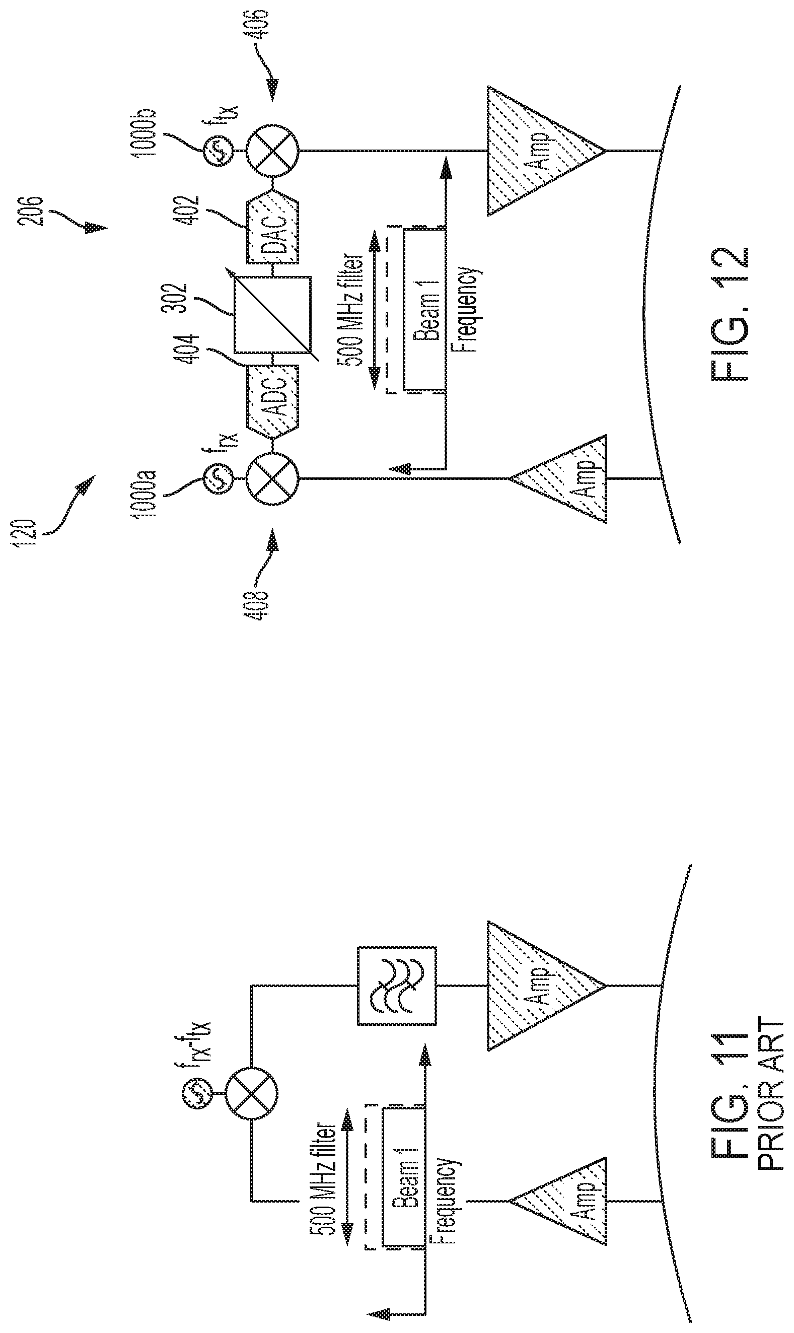
Flexible Bandwidth Embodiment
[0083] FIGS. 11 to 14B show diagrams related to the bandwidth flexibility of the payload communications system 120. FIG. 11 shows a known satellite system in which fixed analog filters permit only one beam to pass through. The filter has a fixed beamwidth of 500 MHz, for instance. This fixed configuration may be acceptable in some circumstances. FIG. 13 shows a circumstance where three beams are received. The fixed bandwidth of the known system causes half of beams `0` and `2` to also pass through the 500 MHz filter.
[0084] In contrast to known satellite systems, the example payload communications system 120 of FIG. 12 includes a digital filter provided by the processor 302 of the SDR 206. In FIG. 12, the SDR 206 is configured to have a bandwidth of 500 MHz to enable the only beam to pass through, similar to the known system of FIG. 11. However, if the desired bandwidth per beam decreases as multiple beams are received, the example SDR 206 is configured to accordingly adjust the bandwidth of the digital filter. For example, in FIG. 14A, the SDR 206 is re-configured to permit only the single beam by reducing the bandwidth of the digital filter to 250 MHz.
[0085] The example SDR 206 is configured to enable the bandwidth to be adjusted between 1 MHz to 1 GHz (or more) via an over-the-update. In some embodiments, the SDR 206 may adjust filters to change the passband. The use of digital filters enables smaller guard bands to be used as a result of sharper channel filtering, which may consume less than 1% of the available frequency spectrum compared to known systems that have guard bands that consume upwards of 10% of the spectrum.
[0086] FIG. 14B shows a diagram comparing channel filtering of traditional analog systems 1402 (shown in FIGS. 11 and 13) and digital channel filtering 1404 provided by the SDR 206. Traditional analog filtering has a greater roll off at the edges compared to digital filtering. As a result, systems that use traditional analog filtering have lower spectral efficiency factor, such as 0.9, and need to allocate larger guard bands, such as 25 MHz. By comparison, the sharper digital filtering has a higher spectral efficiency factor, as high as 99%, and enables smaller guard bands to be used. The digital filtering accordingly provides a greater spectral efficiency factor and provides more available bandwidth for users.
[0087] The flexible bandwidth of the payload communications system 120 enables a service provider to support increases in demand when additional spectrum is not available. For example, a single payload communications system 120 may be reaching capacity with 4 beams of 500 MHz bandwidth. A second payload communications system 120 may be provided operating on the same spectrum, with each being configured to provide 4 beams of 250 MHz bandwidth, which increases total capacity by 40%. The adjustability of the digital filter enables the bandwidth to be reduced so that only the desired beams are processed.
[0088] In another example, the payload communications system 120 is operating at a frequency of 2 GHz, with 4 beams of 500 Mhz. A service provider may be granted an additional 2 GHz of spectrum. Instead of launching another satellite, the service provider adjusts the bandwidth of the digital filters to operate over 4.0 GHz, where the bandwidth of the filters are increased to 1 GHz (4 beams of 1 GHz), thereby automatically increasing capacity by 60% without launching an additional satellite.
Flexible Channelization and Routing Embodiment
[0089] FIGS. 15 and 16 show diagrams related to channelization and routing flexibility of the SDR 206 included within the payload communications system 120, according to an example embodiment of the present disclosure. FIG. 15 shows a known satellite system in which analog transponders provide a rigid network topology as a result of fixed, analog waveguide filters. The illustrated design is fixed during manufacture and provides for a pure hub-spoke design where all signals received on a channel are routed to the same output channel.
[0090] In contrast, FIG. 16 shows a diagram that is illustrative of channelization and routing configured within the processor 302 of the SDR 206. The example SDR 206 includes a digital channelizer configured to enable flexible network topologies by using flexible digital filtering to separate a received signal into many narrowband channels. For each channel, the SDR 206 may change a frequency and select a certain beam for transmission. The selection may be in response to an over-the-air update. For transmission, the SDR 206 may combine many narrow channels assigned to the same beam into a single signal.
[0091] As shown in FIG. 16, the SDR 206 uses digital or physical-layer channel routing to combine received signals on narrow channels from the User RED and GW GRN inputs for transmission via the User GRN output. In other words, the SDR 206 provides for direct routing of data from the User RED input to the User GRN output in addition to routing data from the GW GRN input to the User GRN output. This enables user terminals that receive the GRN output to receive data from other user terminals via the User RED input and data from a gateway via the GW GRN input. It should be appreciated that the SDR 206 may route any channel of the inputs to any of the outputs to provide for a virtually unlimited routing configuration. The routing configuration may be specified by an over-the-air update, a time plan, or be specified in data encoded within the routed data.
[0092] The example SDR 206 may provide routing at one or many different layers. For example, the SDR 206 may be configured to provide physical layer routing such that sub-channels of a specified frequency are routed to another channel. This may be performed for spectrum allocation or load balancing. The SDR 206 may also perform routing at the link or network layer by routing digital data based on MAC or IP address. In these examples, the SDR 206 may include a routing-and-forwarding table that specifies to which sub-channel data is to be routed.
Millimeter-Wave and Optical Gateway Embodiment
[0093] FIGS. 17 and 18 show diagrams related to the GEO communications satellite 100 being configured to provide compatibility with millimeter-wave and/or optical gateway transceivers, according to an example embodiment of the present disclosure. FIG. 17 shows a diagram of a traditional satellite that communicates with gateway transceivers 1700 operating in the same frequency as the use spectrum (i.e., the Ka band) or in another common user link frequency. For instance, the gateway 1700 may operate in the Ka band while the user links located in spot beams 1702 are provided in the Ku band. In this configuration, significant high-value spectrum is consumed by the gateway link with the satellite. In some instances, the limited spectrum available for the gateway 1700 is the bottleneck for network capacity.
[0094] FIG. 18 shows an embodiment of the GEO communications satellite 100, including the SDR 206, configured to communicate with a gateway 1800 that is configured to communicate over a higher frequency compared to user links for spot beams 1802. The higher frequency for the link with the gateway 1800 may comprise the Q-band, the V-band, the W-band, or an optical band, which are generally less suitable for user links and where spectrum is generally more plentiful. Communication over these bands between the gateway 1800 and the satellite 100 provides more bandwidth for the low-frequency, high-value user links in the Ka or Ku band. The use of higher frequencies for the gateway link also enables higher directivity on the gateway link, thereby reducing the transmit power requirements and enabling greater spectral efficiency factor values. This configuration may also reduce the number of gateways needed since frequency reuse is not as critical. As discussed above, the example SDR 206 is configured to provide the frequency flexibility and/or demodulation/modulation needed to enable millimeter-wave and/or optical communication with gateways. In some instances, the SDR 206 may additionally or alternatively be configured to facilitate user links in the higher frequency bands.
[0095] It should be appreciated that the example SDR 206 may also be configured to process different waveforms. Different service providers may have different waveforms, some being proprietary. The SDR 206 may be configured to process a first waveform on a gateway link while processing second different waveforms on a user link. Further, the SDR 206 may receive over-the-air programming to change the waveform being processed by, for example, adjusting digital filter parameters, adjusting DAC/ADC gain values, and/or adjusting carrier frequency/bandwidth.
Flexible Beam Shape Embodiment
[0096] FIGS. 19 to 21 show diagrams related to the beam shape flexibility of the payload communications system 120. FIG. 19 shows a diagram of a coverage area 1902, 1904, 1906, and 1908 of known satellites. Generally, the beam shapes (driven by the radiation pattern of the antenna) are fixed. A gateway station is provided in spot beam 1910.
[0097] FIGS. 20A and 20B shows diagrams of example beams or radiation patterns provided by the example payload communications system 120. In this example, the four narrow beams (provided to coverage areas 1902 to 1908) from FIG. 19 are re-configured by the SDR 206 into a single wide beam, shown as coverage area 2002. The beam may be provisioned for broadcast television, for example. The single elongated beam shown in FIG. 20A has consistent Quality of Service ("QoS") coverage throughout the service area.
[0098] The elongated beam shown in FIG. 20A is one example of a formed beam shape. It should be appreciated that a combined and/or individual shape of beams may take many forms depending on the terrestrial coverage needed. For example, one or more beams may be formed into a triangular coverage area, an L-shaped coverage area, etc.
[0099] FIG. 20B shows an example of a possible beam shape, shown as coverage area 2050. The example SDR 206 may achieve the beam shape shown in FIG. 20B via an over-the-air update which adjusts an amplitude and/or phase of signals entering/leaving each feed on an antenna feed plane. The amplitude and/or phase may be adjusted via a gain varying amplifier, controllable phase shifters, and/or turning on/off certain antennas in an array. The example SDR 206 may provide for separate beam forming for each sub-carrier channel to produce virtually any radiation pattern. As such, the beam forming described herein may be performed digitally within the SDR 206, via analog components, and/or a combination of both.
[0100] FIG. 21 shows a diagram of the SDR 206 configured for providing flexible beam shapes using a phased array, which is described below in additional detail. In the illustrated example, the SDR 206 is configured to route a received signal to four transmitters. (In other embodiments, the signal may be routed to fewer or additional transmitters). The SDR 206 adjusts amplitude and phase of the signal for each transmitter to fine tune the shape of the desired beam. In some embodiments, the SDR 206 receives instructions, including phase and/or amplitude information from a ground station. In other examples, the SDR 206 is configured to select the phases and/or amplitudes based on a received indication of a coverage area, QoS requirements, time plan, etc. The example beamforming calibration network 704 of FIG. 7 may be used to maintain the relative phases and/or amplitudes as the signal propagates through the transmitters.
Beam Hopping Embodiment
[0101] FIGS. 22 to 23B show diagrams related to the beam hopping capability of the payload communications system 120. FIG. 22 shows a diagram of a known satellite system providing a fixed wide-area beam. The known satellites systems are constrained to providing low signal levels throughout the coverage area due to the large geographic area covered. This configuration can be problematic for high throughput cases.
[0102] In addition to providing a flexible beam shape, the example SDR 206 of the payload communications system 120 is configured to enable one or many small beams to be moved within a coverage area, as shown in FIG. 23A. This dynamic configuration enables a relatively large amount of bandwidth to be provisioned for a small geographic location for microseconds to hours or months. In an example, one or more cruise ships may be within a coverage area. Each cruise ship has thousands of passengers that provide a significant bandwidth load in a relatively small area. Instead of a bandwidth-constrained wide beam, the example SDR 206 may create a small beam (shown as coverage area 2300) with high signal levels focused on the cruise ship. In addition, the SDR 206 may cause the beam to follow a path of the cruise ship or jump between cruise ships. As a result, the SDR 206 is able to provide a 5 dB stronger signal while improving average system capacity by 50-100%, for example. The example payload communications system 120 may provide beam hopping for other embodiments, such as satellite service-sharing for providing communication coverage for a large festival or conference that is taking place for a limited duration in a remote location.
[0103] The example SDR 206 may be configured to provide beam hopping based on an over-the-air instruction and/or according to a predetermined routine. The SDR 206 may adjust the location of the beam as quickly as every 5 ms to maximize the gain experienced by a user, thereby increasing capacity on both the forward and return links. The SDR 206 may adjust a beam location by adjusting an amplitude and/or phase of signals entering and leaving each feed on the feed plane, using for example a phased array or any of the operations discussed above in connection with FIGS. 20A, 20B, and 21.
[0104] FIG. 21 shows a diagram of the SDR 206 configured for providing beam hopping. In the illustrated example, the SDR 206 is configured to route a received single to four transmitters. (In other embodiments, the signal may be routed to fewer or additional transmitters). The SDR 206 adjusts a phase of the signal for each transmitter/receiver to move the peak of the transmitted/received beam. In addition, the SDR 206 adjusts phase and amplitude of the signal for each transmitter/receiver to fine tune the shape of the desired beam. The SDR 206 may also adjust the amplitude of the signals.
[0105] In some embodiments, the SDR 206 receives instructions, including phase and amplitude information and a location for the beam (e.g., a position of a cruise ship) from a ground station. In other examples, the SDR 206 is configured to select the phase and amplitude based on a received indication of a coverage area, geographic location, QoS requirements, etc. In other examples, the SDR 206 may track a moving object, thereby determining a location for a beam. The SDR 206 may provide tracking of an object by moving the beam in different directions and determining to which direction has the greatest bandwidth consumption. The example beamforming calibration network 704 of FIG. 7 may be used to maintain the relative phases and amplitude as the signal propagates through the transmitters and/or receivers.
[0106] FIG. 23B shows a diagram that illustrates how an array of antennas feeding a reflector can be selectively turned on to move a beam quickly. Graph 2450 shows a relation between reflector antenna beamwidth (e.g., coverage area on the Earth) in degrees and a feed horn aperture size. The graph 2450 shows that as the aperture size increases from 2 to 12.3 mm, the beamwidth increases from 1.6 to 5 degrees. In a static embodiment, different feed horns with different aperture sizes may be used. The SDR 206 may select which feed horn is to be used based on the coverage area requirement. By contrast, in a dynamic environment, the SDR 206 may be connected to an array of smaller feed horns with identical apertures. The SDR 206 is configured to control excitations of the individual feed horns in the array to create different effective aperture sizes for changing the beamwidth. For instance, in the illustrated embodiment, activating only one element (A) will provide a smallest effective feed size while turning on all the elements (D) will provide the largest feed size. The SDR 206 may achieve anything in between by exciting a subset of the elements in a discrete manner, as shown in (B) or by exciting all elements and controlling the excitations with more granularity for continuous control, as shown in (C).
Large Flexible Aperture Antenna Embodiment
[0107] FIGS. 24 to 25B show diagrams related to capabilities of the GEO communications satellite 100, including the SDR 206, regarding the use of large flexible aperture antennas, according to an example embodiment of the present disclosure. As shown in FIG. 24, known satellites are constructed as single-piece structures such that antenna sizes are limited in diameter. The size limitation on the antenna limits maximum equivalent isotropically radiated power ("EIRP") and gain to noise-temperature ("G/T"), which limits data throughput. Many known satellites, as shown in FIG. 24, use multiple small to medium (e.g., 1 to 2 meter) reflectors.
[0108] FIG. 25A shows an example of the GEO communications satellite 100 having antennas with larger apertures. While the use of large apertures is not new, the use of large flexible aperture antennas on a relatively small GEO communications satellite is unique. The antennas may be stowed for launch and deployed and expanded when the GEO communications satellite 100 is in orbit (hence called "flexible"). The GEO communications satellite 100 may include an unfurlable mesh antenna, an expandable antenna, a deployable or foldable (flexible or solid) antenna, a flexible (compliant solid) antenna, and/or a stowable array antenna (forming various types of flexible antennas). The GEO communications satellite 100 may be configured specifically to provide a larger aperture antenna and provide for a unique deployable structure without constraints from other adjacent antennas or space limitations within the housing. As shown in FIG. 25A, the use of the larger reflector, along with proper feed architecture, enables more spot beams to be provisioned for the same data rate (as shown in FIG. 24) at a substantially lower cost.
[0109] FIG. 25B shows an example regarding how the GEO communications satellite 100 may be launched with a large flexible aperture antenna. In the illustrated embodiment, an antenna is packed into a very small volume during launch (and orbit raise depending on mission requirements). The packing enables an antenna with more than a 5.times. aperture size to be used, which would occupy the same volume as a traditional reflector antenna. After the satellite 100 is positioned, the antenna with the large flexible aperture is unfurled, thereby providing a dramatic savings in time and cost of the mission while providing unprecedented data rates.
Interlaced Beams Embodiment
[0110] FIGS. 26 and 27 show diagrams related to capabilities of the GEO communications satellite 100, including the SDR 206, regarding the use of interlaced beams, according to an example embodiment of the present disclosure. FIG. 26 shows a figure of a known satellite with multiple apertures. In the illustration, the multiple apertures (shown as Aperture 1 and 2) and reflectors 2602 and 2604 provide different interleaved beams. The illustrated configuration requires a large satellite with multiple apertures and reflectors to achieve a tight-arrangement or packing of beams.
[0111] By comparison, FIG. 27 shows a diagram of multiple communication satellites 100 (shown as satellites 100A and 100B) that are arranged to achieve a tight packing of separate beams. In the illustrated example, each of the communications satellites 100 may include only a single aperture such that the beams from each satellite 100 are interleaved. This arrangement of single-aperture satellites 100 enables capacity to be phased-in or a sub-set of capacity to be repointed or any other use/advantage of providing a small, single-aperture satellite. The illustrated satellites 100A and 100B are specifically orientated and coordinated with respect to each other to provide for the tight-packing of beams without having to compensate for aperture or reflector size or orientation, thereby enabling single aperture satellites to achieve the performance of known conventional, multiple aperture satellites.
Low-Element and High-Element Phased Arrays Embodiments
[0112] FIGS. 28 to 30 show diagrams related to capabilities of the GEO communications satellite 100, including the SDR 206, regarding the use of low-element phased arrays, according to an example embodiment of the present disclosure. FIG. 28 shows a diagram of a known satellite where a single feed per beam is configured. The single feed per beam generally results in an inflexible beam footprint on the ground. In addition, power needed to supply the single feed is relatively high to drive costly, but highly efficient, conventional traveling wave tube amplifiers.
[0113] FIG. 29 in contrast shows the satellite 100 with the SDR 206 having a relatively low number of feed elements, shown as eight elements 2902 to 2916. Generally, phrased arrays are complex to implement based on the large number of elements needed. However, the example SDR 206 reduces element complexity via dynamic digital control of the amplitude and phase for the elements in the array. The SDR 206 provides software control of amplitude and/or phase of each transmission/reception signal for each feed. As discussed above, this amplitude and/or phase flexibility enables dynamic beam shapes and beam-hopping. In some instances, a relatively low element count phased array may not generate the directivity needed for a link. As a result, the GEO communications satellite 100 may include one or more reflector surfaces to improve link directivity.
[0114] FIG. 30 shows the satellite 100 with the SDR 206 having a multiple feed for a relatively large number of elements. The satellite 100 may include a large number of low-power solid state power amplifiers ("SSPAs"), high element count, and/or software control of signal amplitude and/or phase via the SDR 206. The illustrated configuration enables a highly directive, highly steerable beam footprints. In addition, the illustrated phased array is configured to directly radiate towards the Earth, thereby removing the need for any reflectors.
Noise Removal Embodiment
[0115] FIGS. 31 to 33 show diagrams related to the noise removal capability of the payload communications system 120. FIG. 31 shows a known satellite in which noise is propagated from uplink (receive) to downlink (transmit). This causes the known satellite to transmit degraded signal quality, and waste power on noise transmission, which could lead to losses in signal strength by up to 6.5 dB.
[0116] FIG. 32 shows a diagram of the example payload communications system 120 removing virtually all interference and noise from a signal before retransmitting to a gateway or user terminal. In the illustrated example, the signal to noise ratio is maintained at 10 dB. This can be especially important when the payload communications system 120, via the SDR 206, is configured to route traffic between adjoining beams, which may create signal interference. By removing the noise and interference between the adjacent beams, the SDR 206 is capable of improving signal quality by more than 3 dB at the user terminal, thereby increasing capacity by over 30% between the adjoining beams.
[0117] FIG. 33 shows a diagram of the example SDR 206 regarding its noise removal capabilities. To remove noise, the example SDR 206 is configured to demodulate and decode a received signal into a digital or binary stream of `1s` and `Os` (e.g., a sequence of information bits). This may be provided in conjunction with signal routing between slices, as described above in regards to network topology. For transmission, the digital signal is reconstructed via modulation and encoding and transmitted on the desired slice.
[0118] The example SDR 206 is configured to remove noise in any waveform via an over-the-air update specifying, for example, the waveform parameters for modulation in addition to processing and filtering. In some examples, the SDR 206 may operate in connection with hardware components configured to remove noise from a signal. Additionally or alternatively, the SDR 206 may provide noise removal via regenerative digital signal processing.
Compressed Gateway Spectrum Embodiment
[0119] FIGS. 34 and 35 show diagrams related to the compressed gateway spectrum capability of the payload communications system 120. FIG. 34 shows a diagram of a known satellite system in which a modulation and encoding scheme is provisioned in which an eight symbol constellation is used on the user links and the same eight symbol constellation is used on the gateway links, where the modulation is the same for the user and gateway links. In some known systems, the satellite system may be provisioned such that a different modulation and encoding scheme is used for the gateway link because the gateway terminal is larger. This enables the modulation used for the gateway to be more spectrally efficient. However, the known satellite systems are fixed in that the modulation and coding cannot be changed after deployment. Thus, if conditions change or service is provided for a different provider, the provisioned modulation and encoding scheme may not be sufficient. For example, a smaller gateway could be installed or used. However, the known satellite has already been provisioned to operate efficiently with a larger gateway.
[0120] In some instances, the gateway and user links may use the same modulation and coding for known satellite systems. The gateway link may use the same modulation and coding despite the gateway link having significantly more carrier-to-noise ("C/N") margin. The reason for this is because convention transponders on known satellites are incapable of altering the modulation and coding of a received signal before retransmitting.
[0121] The example payload communications system 120 of the GEO communications satellite 100 of FIG. 35 is configured to change modulation and encoding schemes for any of the user or gateway slices. For example, upon use of a larger gateway, the SDR 206 may change a modulation and coding scheme to one that is more spectrally efficient, thereby allowing spectrum to be repurposed and used to increase system capacity or throughput by at least 15% without increasing the spectrum allocated to the gateway. This additional spectrum can be used for serving additional content, for example. In other words, spectrum saved on the gateway link can be provided by the SDR 206 for user links. In the illustrated example, the SDR 206 may provide eight symbols on user links or slices for communication with user terminals 3502 and 64 symbols on the gateway links for communication with gateway stations 3504. Accordingly, the SDR 206 enables the modulation and coding for the gateway link to be independent of the modulation and coding used for the user links, which are often C/N limited.
[0122] FIG. 33 shows a diagram of the example SDR 206 regarding compressed gateway spectrum capabilities. The example SDR 206 has software-based demodulators/decoders and modulators/encoders. The SDR 206 may select between the different programmed or available demodulators/decoders and modulators/encoders for each slice or link. Alternatively, a demodulators/decoders and modulators/encoders may be provided via an over-the-air update. The demodulator/decoder and modulator/encoder selection/provision may be provided in conjunction with signal routing between slices, as described herein regarding network topology. For transmission, the digital signal is reconstructed via the selected modulation and encoding and transmitted on the desired slice or link.
Equalization Embodiment
[0123] FIGS. 36 and 37 show diagrams related to the equalization capability of the payload communications system 120. Generally, known satellite systems are not capable of providing equalization. Instead, user terminals provide equalization of the received satellite signal. However, equalization performance by ground receivers is limited since significant thermal noise has been introduced before the equalization is performed. FIG. 36 shows that for known systems, user terminals equalize the received signal but amplify the noise significantly in the process. The amplification of noise, especially at higher frequencies, can lower throughput by at least 10%, especially when operating in ultra-wideband channels, such as 500 MHz and above.
[0124] In contrast to known satellite systems, the example SDR 206 of the payload communications system 120 (included in the satellite 100) is configured to equalize the signal before downlink noise is added, thereby leaving a relatively small amount of equalization to be done by the user terminal. As shown in FIG. 37, the example SDR 206 is configured to provide digital equalization, which corrects for (i) different frequencies having slightly different gains/losses passing through the atmosphere (e.g., rain, clouds, scintillation in the troposphere), filters, amplifiers, etc., and (ii) different frequencies taking different amounts of time to propagate through the atmosphere, filters, amplifiers, etc. that may affect or introduce signal gain slope, reflections, and/or group delay distortion. The equalization performed by the SDR 206 means there is less amplification of noise by the user terminal, and thus a higher capacity link, thereby improving the data rate of the system.
[0125] The example processor 302 may include a 12-bit complex tap applied to each 2 MHz subcarrier, as described above in connection with the network topology flexibility. The processor 302 in other embodiments may include an 8-bit complex tap up or any other complex tap up to a 24-bit complex tap. In some instances, the taps may be determined via calibration over temperature and frequency, or in a closed loop adaptive fashion.
Flexible Network Topology Embodiment
[0126] FIGS. 38 to 41 show diagrams that compare known satellite systems and the example GEO communications satellite 100 regarding network topology flexibility. FIG. 38 shows a diagram of coverage areas 3802, 3804, 3806, and 3808 for known satellite systems. The systems are configured in a hub-and-spoke configuration where at least one beam 3800 is dedicated for a gateway station while separate beams are provided for user terminals. In this hub-and-spoke configuration, the satellite system causes all communications to be routed through the gateway station, which determines whether the communications are to be routed to another user terminal in the same or a different beam.
[0127] In contrast to the known satellite systems, the example payload communications system 120 is configured to be able to support virtually any network topology, including mixing network topologies. FIG. 39 shows an example of network topologies supportable at the same time by the example payload communications system 120. Similar to the known systems, the payload communications system 120 supports a hub-and-spoke topology. Additionally, the example SDR 206 of the payload communications system 120 enables other network topologies to be supported, such as user-to-user (shown as links 3902a, 3902b, 3902c, and 3902d), mesh, and/or a combination of hub-spoke and user-to-user. In some embodiments, the network topology may vary over many time scales (e.g., seasonally, daily, hourly, etc.). The SDR 206 is configured to adjust to the network topology via over-the-air software or digital logic updates, which provides flexible channelization and routing for steering traffic.
[0128] The SDR 206 may be provisioned via over-the-air programming to support a specified topology. In a combined topology, the SDR 206 may route data based on network or link layer protocols to enable data to be transmitted in a return link or routed to another satellite. In an example, the SDR 206 (and/or a ground station) may detect that a gateway link or beam is close to capacity. However, a significant amount of traffic originates and ends in the same beam. Instead of sending this identified traffic to the gateway station (as is done by the conventional satellite in FIG. 38), the example SDR 206 is configured to route the traffic back through the beam to the destination terminals, thereby reducing the traffic on the gateway beam. Thus, the SDR 206 saves gateway spectrum and power and improves networking speeds by eliminating one receive/transmit route on the gateway link. The SDR 206 may read a destination address (and/or use geolocation data related to the destination terminal) to identify to which beam a communication message or data is to be routed.
[0129] In another example, the SDR 206 (and/or a ground station) may detect that a large data center is located in a user beam or link. Instead of sending all of the traffic through the gateway link, the SDR 206 is configured to determine user beams for the traffic. Accordingly, the SDR 206 routes network traffic directly to a destination user terminal, thereby saving bandwidth usage on the gateway link and improving network latency.
[0130] FIG. 40 shows a diagram of the example SDR 206 configured to support multiple network topologies. Sub-channels can be flexibly linked across slices by the SDR 206, enabling network traffic to be routed internally within the example payload communications system 120, rather than sending all received communications to a ground-based gateway station. In the illustrated example, more of the bandwidth is reserved for routing to/from a gateway station. However, at least some bandwidth is allocated between the different user slices (e.g., links or beams). For example, 100 MHz of bandwidth is provisioned between the `User BLU` user slice input and the `User RED` user slice output and 50 MHz of bandwidth is provisioned between the `User RED` user slice input and the `User BLU user slice output. It should be appreciated that in some embodiments, each user slice may have at least some bandwidth allocated for routing traffic to each of the other user slices (as well as the gateway slice).
[0131] FIG. 41 shows a diagram of features of the SDR 206 for providing a flexible network topology, in some embodiments. The example SDR 206 is configured to separate the received signals into many narrowband channels. For example, a 1.0 GHz signal may be separated into 500 2.0 MHz subcarriers. In other examples, a 1.0 GHz signal may be separated into 2, 500 MHz subcarriers or 250, 4 MHz subcarriers. This configuration removes adjacent channels to the 1.0 GHz signal (to -40 dBc). The SDR 206 may achieve channel separation via a polyphase filter bank, or any digital filtering structure. The polyphase filter may have, for example, an input sample rate of 1250 MHz for 14 bit I and Q, a pass band of 1.0 MHz with 2.0 MHz two-sided passband, a stop band start of 3.0 MHz, a transition band of 2.0 MHz, a pass band ripple of 0.1 dB, and a stop band rejection of 92.0 dB to ensure aliasing into the passband is at most -40 dBc in the presence of adjacent interference at +26 dBSD. After the channels have been separated in the SDR 206, the channels may be individually routed, as shown in FIG. 40.
[0132] For signal routing, the example SDR 206 is configured to change the frequency and/or beam assignment for specified narrowband channels. The SDR 206 then combines the many narrowband channels for each transmit beam before transmitting. The SDR 206 may achieve signal construction via a polyphase filter bank, or any digital filtering structure.
Intersatellite Linking and Mesh Networking Embodiments
[0133] In some embodiments, the example GEO communications satellite 100 may operate in coordination with other similar communication satellites 100. FIG. 42 shows a diagram of an example operating environment 4200 in which communication satellites 100a, 100b, and 100c operate together and are co-located within a single GEO orbital slot. In the illustrated example, the communications satellites 100a, 100b, and 100c are providing communication coverage to an area 4202 on the Earth 4204. In addition, the GEO communications satellite 100d is provisioned as a spare. While the illustrated example shows four satellites, it should be appreciated that other operating environments may include fewer or additional satellites. For example, the environment 4200 may include 10 to 40 (for example, around 15) relatively small satellites providing communication coverage to a continuous area or separate areas that are relatively close in proximity compared to a size of Earth's surface area (e.g., covering the main islands of Indonesia). In addition, the operating environment 4200 may include at least two spare satellites 100d.
[0134] The communication satellites 100 are provisioned such that satellites 100a, 100b, and 100c are each assigned a coverage area. The spot beam placement, satellite orientation, coverage areas, coverage shapes, bandwidth/channel allocation, frequency use/reuse, coding/encryption protocols, and/or network topology provided by the satellites 100 is configurable via respective SDRs 206. The communication satellites 100 may be provisioned with the communication parameters prior to launch and/or post launch via a ground station 4206. The provisioning of the satellites 100 causes them to operate together to provide continuous, substantially uniform communication coverage to an area on the ground.
[0135] In some embodiments, the satellites 100 are configured to communicate with each other. In these embodiments, the satellites 100 each include a wireless transceiver and antenna that is configured to transmit and receive communication parameters and instructions outside of a frequency channel/band that is used for providing services to ground units. In some embodiments, the satellites 100 may be configured to communicate over a microwave or optical band in a mesh network. The satellites 100 may also have steerable or directional antennas that are configured to point to an adjacent satellite, thereby creating a mesh network. In other instances, the satellites 100 may have unidirectional antennas due to the close proximity of spacecraft.
[0136] In contrast to the embodiment shown in FIG. 42, known commercially produced satellites communicate only with user terminals or gateways on the ground. Generally, the satellites are not configured to communicate with each other. Oftentimes, the satellites are not visible to each other or are too far away to enable effective intersatellite communication. For example, FIG. 43 shows known satellite configurations where data can only pass between two satellites through the ground stations or gateways.
[0137] In some instances, the mesh configuration of the satellites 100 shown in FIGS. 42 and 44 may provide gateway sharing or direct user-to-user connections. The mesh network enables more flexible network topologies, spectrum savings, power savings, and lower latency. The mesh configuration provided at least by the satellites 100a and 100b enables direct user-to-user connections, thereby saving transmission time and reducing lag. As discussed above, the SDR 206 is configured to use link-layer or network-layer routing to determine which data packets are to be transmitted on a sub-carrier, or over a particular intersatellite link 4402. In addition, the mesh configuration enables more flexible network topologies, spectrum savings, power savings, etc.
[0138] In some examples, the SDRs 206 may be configured to determine when capacity has been reached, or close to being reached. Accordingly, the SDRs 206 may send instructions to one or more adjacent satellites 100 with information indicative of the spot beams in which capacity is limited, causing one or more other satellites (with available capacity) to change at least one of the spot beam's shape/location, frequency, bandwidth, etc. to provide additional capacity. This enables additional satellites 100 to overlay more capacity for a certain geographic area on top of existing beams.
[0139] In addition to providing coordination for capacity, the satellites may communicate among each other to cover when one satellite is taken offline for software updates/refreshes, taken offline due to low battery power, taken offline to correct an operational issue, or removed from service. The satellites 100 may also communicate among each other to adjust for local weather or other environment issues and/or adjust for changes in population density. As such, the satellites 100 may reconfigure themselves to account for satellites going offline. In the illustrated example, the satellites 100 may be programmed with a complete coverage area in addition to the capabilities of the satellite 100d, which may be used to being a provision of new services. The satellites 100a to 100d may then coordinate in orbit among themselves to best maintain the desired coverage area using the flexibility provided by the SDR 206.
[0140] In some instances, the satellites 100 may be in communication with the ground station 4206, which may provide provisioning or over-the-air instructions via a wireless link. The satellites 100 may be in direct communication with a ground station via a directional antenna or communication with the ground station 4206 via communication gateways that are located in coverage areas. In this instance, the satellites transmit their capacity, bandwidth, and other parameters to the ground station 4206. The example ground station 4206 uses one or more optimization algorithms to change the communication parameters to address current conditions. In this example, the ground station 4206 determines how each satellite 100 should be provisioned and transmits one or more messages to the appropriate satellites 100 with the new provisioning information.
[0141] In other instances, the satellites 100 and the ground station 4206 are configured to operate together to dynamically change communication coverage. For example, the satellites 100 may communicate among each other to adjust for relatively minor issues (and transmitting this information to the ground station 4206) while the ground station 4206 provides commands for relatively larger changes in provisioning/adjusting communication parameters and/or orbits. In some instances where the satellites have limited or no inter-satellite communication capability, the ground station 4206 and/or gateways may route provisioning or control instructions for coordination between the satellites 100.
[0142] In the illustrated example, the satellite 100d is provisioned as a spare. Given the relatively small and inexpensive nature of the satellites, an operator can deploy spares without absorbing a significant cost or needing to seek an immediate return. The spare satellite 100d may be in the same orbital location as the other satellites 100a, 100b, and 100c. Alternatively, the spare satellite 100d may be assigned to a different orbit. The example spare satellite 100d may quickly be brought online in near real-time to provide, for example extra capacity or provide as a backup in the event one of the other satellites 100a to 100c goes offline. The spare satellite 100d may receive provisioning instructions (and/or orbital realignment instructions) from at least one of a satellite 100 that has been (or will be) taken offline, a satellite 100 operating at close to capacity, one of the satellites 100 provisioned to provide coverage close to an area where the satellite 100d is to operate, and/or the ground station 4206.
[0143] The configurability and coordination among the relatively small satellites 100 via the SDR 206 enables coverage areas to be tuned to ground demographics and/or topography. This enables the satellites 100 to be placed strategically. By comparison, relatively large satellites are designed to provide communication coverage to wide areas and are generally static in their deployment for the reasons discussed above. The post-deployment configurability of the satellites 100 permits operators to construct coverage areas that match the ground. For example, coverage areas could be positioned along major transportation lines, population centers, and ground topology. This prevents, for example, bandwidth from being wasted in open water, deserts, or mountainous areas. The coverage areas may take on any shape since multiple satellites 100 may coordinate together, each capable of forming their own beam shapes. Ground patterns may include s-shapes, narrow lines or bands, rings, triangles, rectangles, etc. (with no or reduced coverage in the center), grids, etc.
Specially Provisioned Satellite Embodiments
[0144] FIGS. 45 and 46 show diagrams related to how the example communications satellites 100 may be specially provisioned for one particular task, according to an example embodiment of the present disclosure. FIG. 45 shows a diagram of a known satellite system in which two parabolic dishes 4502 and 4504 are used, where one dish 4504 is used for transmission and another dish 4502 is used for reception. In some instances, the reception dish 4502 is made less parabolic to achieve the same directivity as the transmit dish 4504 despite the higher frequency of the received signals. Overall, the known system provides a compromise between the reception and transmission side, or optimizes for transmission while making reception significantly less efficient or robust.
[0145] In contrast, the example communication satellites 100 of FIG. 46 are configured for intersatellite communications, as discussed in connection with FIGS. 42 and 44. In this embodiment, the satellite 100a is optimized for uplinks while the satellite 100b is optimized for downlinks. In other words, the aperture of the satellite 100a is optimized for receiving signals while the aperture of the satellite 100b is optimized or specifically shaped for transmission. For transmission to the ground, the satellite 100a transmits signals to the satellite 100b via an intersatellite link 4602, which then provides for downlink transmission. The SDR 206 in each satellite 100 enables the signals to be routed across channels as part of the transmission path.
[0146] Generally, since the satellites 100 are smaller, compared to a single satellite shown in FIG. 45, they may be developed faster with less overall cost. Further, it is easier to add smaller satellites to a launch schedule since a single rocket does not need to be dedicated to launch only these specific satellites. For example, the satellites 100 may find room in a rocket configured to launch many smaller satellites.
[0147] It should be appreciated that the satellites 100 may be specialized in other ways other than transmission and reception. For example, FIGS. 47 and 48 show how the satellites may be configured based on link type. FIG. 47 shows a diagram of a known satellite system in which satellites have gateway transmitters and receivers capable of providing all user links. Accordingly, each satellite has to be in communication with at least one gateway 4702.
[0148] In contrast, FIG. 48 shows an embodiment where the satellites 100a and 100b use an intersatellite link 4602, as discussed above in connection with FIGS. 42 and 44 to enable the satellite 100b to be specifically configured for providing only user links for user terminals 4802. The SDR 206b of the satellite 100b is configured to use physical, network, and/or link layer routing of gateway traffic to the satellite 100a via the intersatellite link 4602. The SDR 206a of the satellite 100a is configured to add the data from the satellite 100b to the gateway link for transmission to the gateway 4702. As such, both satellites 100a and 100b share the same gateway 4702 while enabling the satellite 100b to be specifically configured for providing user links. This configuration alleviates the need for additional gateways, which can save a customer millions of dollars. Further, the satellite 100b may be provisioned to provide service in situations where a gateway is not present.
Frequent Body Repointing Embodiment
[0149] FIGS. 49 and 50 show diagrams related to frequent body repointing features of the GEO communications satellite 100, according to an example embodiment of the present disclosure. FIG. 49 shows a diagram of a known satellite system in which the satellite contains a large number of transponders that serve many markets. Given the spread of the markets, the satellite is required to stay in the specified orientation, since a small shift could cause a service disruption in one or more areas. Further, many known satellites are not capable of re-pointing since they rely on horizon sensors to maintain a specified orientation.
[0150] In contrast, FIG. 50 shows a diagram of the example GEO communications satellite 100, which is configured to repoint. The satellite 100 has a capacity and coverage area that is generally below the capacity demand variation of a given network. As such, the satellite 100 may be configured to re-point towards peak demand on a seasonally, weekly, daily, or hourly basis. For example, the satellite 100 may follow prime time demand across different time zones. The satellite 100 achieves frequent re-pointing via flexible attitude determination, such as star-gazer sensors and/or a sun sensor. This flexibility enables the satellite to point anywhere on the visible earth during its lifetime. In addition, the small size of the satellite 100 enables sufficient power margins to enable frequent re-pointing.
Frequent Orbital Relocation Embodiment
[0151] FIGS. 51 and 52 show diagrams related to frequent orbital relocation features of the GEO communications satellite 100, according to an example embodiment of the present disclosure. FIG. 51 shows a known satellite initially covering the continental United States from an orbital slot of 90 W. The satellite is designed and configured on the ground before launch such that the antennas provide beams that coincide with the borders of the U.S. The antennas are fixed in place to provide a fixed beam pattern in addition to a frequency plan. Thus, if the satellite is moved to slot 10E, the beam pattern of the U.S. would provide insufficient coverage of land and water over Europe and North Africa and the Middle East.
[0152] In contrast, FIG. 52 shows a diagram in which the example GEO communications satellite 100 is initially providing coverage over cruise lines in the Caribbean from orbital slot 90W, as shown as coverage area 5202. At a later time, the satellite 100 is moved to slot 10E, where beam shapes and coverage areas may be modified to cover cruise lines in the Mediterranean Sea, as shown as coverage area 5204. This configuration enables the satellite 100 to change orbital slots on a frequent basis, such as a seasonal or monthly basis. The flexible frequency, beam shape, and flexible channelization provided by the SDR 206 in addition to hardware enables better re-use over different geographic areas. Further the smaller size of the satellite 100 reduces the amount of fuel needed for relocation to enable many relocations over a lifetime.
Small Capacity and Fast Build Embodiment
[0153] FIGS. 53 and 54 show diagrams related to how a smaller capacity of the example GEO communications satellite 100 enables lower cost for covering the same area on the ground or air, according to an example embodiment of the present disclosure. FIG. 53 shows a known satellite system that typically costs $150 to $400 million to produce and launch. The satellite is configured to cover the entire continental United States with over 50 static beams. As such, the known satellite has a custom payload, which is purpose-built for a given service region. This customization requires long development time for design and manufacturing, which can span over three years. Further, since the satellite requires a dedicated launch, launch opportunities are more limited.
[0154] In contrast, FIG. 54 shows the example GEO communications satellite 100, which costs a fraction of the larger satellite of FIG. 53. As shown in the illustrated example, the satellite 100 provides fewer beams as a result of its smaller size. However, additional similar satellites 100 may be deployed to cover the entire continental United States, which is still less expensive than the single satellite. Further, as described above, the satellites are flexible and can individually be adjusted after launch based on ground conditions, customer requests, etc. In contrast, the known satellite of FIG. 53 is only provisioned for providing coverage for the Eastern continental United States.
[0155] The GEO communications satellite 100 may be available off-the-shelf or be developed and built in a shorter time, such as 18 months. The above described flexibility of the satellite 100 means that less customization per customer is needed, thereby reducing development time. Many nearly identical satellites 100 may be built together to dramatically reduce non-recurring engineering effort and provide for a constant supply chain and holding stock. The satellites may be built during the same run on a production line, thereby having a shorter lead time, higher throughput, and lower overall cost. Further, the smaller size of the satellite 100 provides more launch opportunities.
Use Embodiments
[0156] The example GEO communications satellite 100 described above may be provisioned for various uses in which conventional, known satellites cannot be deployed for technical or economical reasons. The features described above in relation to the SDR 206 and the satellite 100 enable implementation of the novel uses discussed below. For example, the relatively small and inexpensive nature of the communication satellites 100 disclosed herein enable the satellites to be deployed to test or develop an initial market. The low cost of the satellite also reduces the cost risk for an operator, compared to the cost of a larger satellite. The smaller satellite could be deployed to test how much demand there is for satellite service in a certain area, or provide coverage as part of an incentive to market and develop satellite service in a particular area. As demand increases and the market is established, the satellite 100 could be replaced by a larger satellite, or additional satellites 100. The additional satellites 100 may also enable the coverage area to be expanded to larger geographic areas, thereby scaling communication coverage in proportion to demand.
[0157] FIGS. 55 to 65 below describe at least some of the unique uses of the example satellite 100. It should be appreciated that any individual satellite 100 having the SDR 206 may be provisioned to perform all the described uses or only a subset of the uses. Further, while the features shown in chart 800 of FIG. 8 enable the uses, it should be appreciated that not every feature is required for the use to be implemented. For example, for testing a new market, any of the flexible carrier frequency, flexible bandwidth, flexible channelization and routing, flexible beam shape, and flexible network topology may be enabled on the satellite 100 and implemented in the SDR 206.
A. Testing a New Market
[0158] FIG. 55 shows a diagram related to a use of the GEO communications satellite 100 for testing a new market, according to an example embodiment of the present disclosure. New geographic and vertical markets may require connectivity that is best served by satellites. However, as new markets, the economic hypothesis needs to be tested without dedicating a significant investment. Known satellites are too expensive and inflexible to be deployed in a new market. Instead, the example satellite 100 provides the low-cost and flexibility required to test new coverage areas. As shown in FIG. 55, the new markets may include vehicles 5502 (e.g., ships, buses, cars, etc.) with satellite connectivity that are located in geographic areas that are not currently served by satellites. Flexible carrier frequency, flexible bandwidth, flexible beam shapes, flexible network topology, frequent orbital relocation, fast build and delivery to orbit, and small capacity for low cost individually or in any combination enable the satellite 100 to test for new markets.
[0159] In an example, a potential customer may desire to test a market using a specified carrier frequency having a defined bandwidth and network topology. The satellite 100 with the SDR 206 may be configured via over-the-air programming to switch to the specified carrier frequency, bandwidth, and network topology using the feature adjustments discussed above. After the market test has been completed, the satellite 100 may be re-deployed for another user that may require a different carrier frequency, bandwidth, and/or network topology.
B. Filling in Coverage Gaps
[0160] FIG. 56 shows a diagram related to a use of the GEO communications satellite 100 for filling in gaps in existing coverage. Locations 5602 represent coverage areas provided by traditional, known satellites. As an example, there is a gap in coverage along the North Atlantic route. This gap is not covered commercially given the relatively high cost of deploying an additional conventional satellite. In other instances, conventional satellites trade off coverage for performance and cost, thereby creating gaps in areas.
[0161] In the illustrated embodiment, the satellite 100 is deployed for filling in the North Atlantic route, as shown by highlighted coverage areas 5604. The fast build and delivery to orbit in addition to the low cost enables the satellite 100 to be deployed for providing economical coverage in a known gap. In addition, the SDR 206 may provide flexible beam shapes to cover uniquely-shaped gaps, as discussed above.
C. Rapid Response to New and Changing Markets
[0162] FIG. 57 shows a diagram related to using the GEO communications satellite 100 for providing rapid response to new and changing markets. It should be appreciated that conditions on the ground are constantly changing. For example, urbanization, commercialization, immigration, new technologies, and other socioeconomic factors change market needs and can accordingly shift coverage needs to new or different geographic areas. Traditional known satellites cover large areas ranging from tens to thousands of customers. The dynamics of these large areas can change over time, thereby rendering satellite coverage unnecessary in some covered areas. While this occurs, the satellite misses opportunities for coverage elsewhere and is inflexible to adapt to new markets. In addition, larger satellites are more difficult to steer or relocate, making any coverage changes extremely difficult.
[0163] In contrast to known satellites, the example GEO communications satellite 100 can be quickly deployed based on demand. For example, FIG. 57 shows the GEO communications satellite 100 providing coverage for the Western United States and Texas in 2018. However, based on changes, in 2020 the GEO communications satellite 100 is deployed to eastern parts of the United States. Flexible carrier frequency, flexible bandwidth, flexible beam shapes, beam hopping, flexible network topology frequent body repointing, frequent orbital relocation, and fast build and delivery to orbit individually or in any combination enable the satellite 100 to provide a rapid response to new and changing markets.
D. Bridging Traditional GEO Capacity
[0164] FIG. 58 shows a diagram related to using the GEO communications satellite 100 for bridging traditional GEO capacity. In some instances, a plan may be in place to provide satellite coverage to a large geographic area, as shown by the coverage area planned for satellite 5800. However, as described above, traditional satellites usually require at least three years of lead time. In the meantime, a subset of higher-priority customers with the geographic area 5802 may require coverage sooner. Rather than go without coverage, the example satellite 100 may be quickly deployed to provide coverage for the critical areas 5802. After the satellite 5800 comes online a few years later, the satellite 100 may be redeployed for another use. Flexible carrier frequency, flexible bandwidth, flexible beam shapes, beam hopping, flexible network topology, frequent body repointing, frequent orbital relocation, fast build and delivery to orbit, and small capacity for low cost individually or in any combination enable the satellite 100 to bridge traditional GEO capacity.
E. On-Orbit Redundancy and Response to Failures
[0165] FIG. 59 shows a diagram related to using the GEO communications satellite 100 for providing on-orbit redundancy and rapid response to failures. In the illustrated example, satellites 100d are provisioned initially as spare or redundant satellites. If a satellite experiences a failure, the redundant satellite can quickly come on line and take the place of the failed satellite. The lower cost of the satellites means less capital is expended to provide satellites with redundancy or backup. Flexible carrier frequency, flexible bandwidth, flexible beam shapes, beam hopping, flexible network topology, frequent body repointing, frequent orbital relocation, fast build and delivery to orbit, and small capacity for low cost individually or in any combination enable the satellite 100 to provide on-orbit redundancy and response.
[0166] In contrast, known commercial satellites are not deployed solely for redundancy based on their cost. Some known satellites may have redundant transponders for backup. However, this is not sufficient backup for system-level failures or in the event the satellite goes completely offline.
F. Bring-Into-Use ("BIU")
[0167] FIG. 60 shows a diagram related to using the GEO communications satellite 100 for providing BIU services. On occasion, the FCC or other government bodies make spectrum (e.g., a specific set of frequencies) available to the public or for specified commercial purposes. Generally, satellite operators are given priority access if they can deploy a satellite for the newly available slot within three years. As discussed above, traditional satellite programs can require at least 3 to 4 years to place a new satellite into orbit, which makes meeting a BIU deadline difficult. Further, customer requirements cannot be easily repurposed for a BIU application, especially if the customer requirements are not yet known or developed.
[0168] In contrast, the example satellite 100 may quickly be brought into use. For example, a satellite may be developed and launched in as soon as 18 months, meeting the BIU launch requirements. In other instances, a customer may request access to a redundant or spare satellite 100d that is already in orbit to provide almost instantaneous BIU. In yet other instances, one of the satellites 100 may use beam hopping to test a new BIU spectrum/location before a license expires to determine if renewal is justified. In addition, flexible carrier frequency, frequent body repointing, frequent orbital relocation, fast build and delivery to orbit, and small capacity for low cost individually or in any combination enable the satellite 100 to provide relatively fast BIU services.
G. Lower Cost Per Mb/s Coverage
[0169] FIG. 61 shows a size comparison between a conventional satellite and the example GEO communications satellite 100 disclosed herein. A conventional satellite costs between $300 to $500 million to develop and launch based on lead time. For example, a satellite that requires a lead time of over five years can cost over $300 million to develop in addition to $100+ million to launch, while a satellite that requires between three to five years of lead time can cost between $150 to $400 million to develop and launch. By comparison, the example GEO communications satellite 100 disclosed herein costs between $10 to $20 million, approximately, and can be developed in as short as 18 months. The example GEO communications satellite 100 has lower power consumption as a result of having fewer antennas, less system hardware, smaller system busses, and a smaller overall platform. The lower power consumption enables the example GEO communications satellite 100 to have smaller solar arrays. Further, the smaller size makes it much easier to repoint and reposition the example GEO communications satellite 100.
[0170] The example SDR 206 provides flexibility, as described above, which when combined with the small size and unique large antenna enables a high throughput, which lowers the cost per MB/s. The lower cost makes it more attractive to deploy the example GEO communications satellite 100 for most cost-sensitive markets. All of the features described above individually or in any combination enable the satellite 100 to provide lower cost per MB/s coverage. In particular, the features of flexible carrier frequency, beam hopping, large flexible aperture antenna, noise removal, compressed gateway spectrum, equalization, flexible network topology, frequent body repointing, frequent orbital relocation, fast build and delivery to orbit, and small capacity for low cost individually or in any combination enable the satellite 100 to provide this use.
H. Phased-in Capacity
[0171] FIG. 62 shows a diagram related to using the GEO communications satellite 100 for phasing-in capacity. Graph 6202 shows how much bandwidth is wasted when a traditional satellite is initially deployed. As described above, traditional satellites have a significant amount of capacity. However, it may take up to a decade for all of the capacity to be leased. The idle capacity over this decade leads to a high cost per unit.
[0172] In contrast, graph 6204 shows how the satellites 100 may be incrementally deployed to scale with capacity. This enables a satellite operator to efficiently increase capacity over time to match demand without having excess unused capacity. After ten years in the illustrated example, the five satellites serve the same market at the same time, and may be configured to provide interlaced beams. Flexible carrier frequency, flexible bandwidth, flexible beam shapes, beam hopping, interlaced beams, flexible network topology, fast build and delivery to orbit, and small capacity for low cost individually or in any combination accordingly enable the satellites 100 to provide phased-in capacity.
I. Augmenting Existing Capacity
[0173] FIG. 63 shows a diagram related to using the GEO communications satellite 100 for augmenting existing capacity. In many cases, a single known, conventional satellite is close but not sufficient to meet the demands of a region. Deploying a second traditional satellite to completely meet the demands may not be cost efficient. Coverage areas in growth zones are especially prone to running out of satellite capacity.
[0174] In the illustrated example, the shaded regions show satellite ground coverage. Region 6302 corresponds to a location where existing satellite capacity has been exhausted. It is usually cost prohibitive to deploy a $300 million satellite to accommodate the growth. Instead, the example GEO communications satellite 100 may be configured to provide beams 6304 to address the capacity issue, thereby providing capacity for growth. In this manner, the example GEO communications satellite 100 may augment capacity provided by traditional satellites. Flexible beam shapes, beam hopping, large flexible aperture antenna, noise removal, compressed gateway spectrum, equalization, flexible network topology, fast build and delivery to orbit, and small capacity for low cost individually or in any combination accordingly enable the satellites 100 to provide augmented capacity.
J. Serving Time-Varying Coverage
[0175] FIG. 64 shows a diagram related to using the GEO communications satellite 100 for serving time-varying coverage. Mobility markets, such as aero and land mobile, as well as traditional markets can have shifting coverage needs that vary over time, such as seasonally, weekly, daily, hourly, etc. Traditional satellites are inflexible and provide service to a mix of mobility and non-mobility based customers that have different needs. As a result, the satellite is prevented from serving time-varying needs in a cost effective manner without sacrificing coverage or high capacity utilization for at least some customers. In other words, large satellites typically cannot move one beam without affecting the other 50 to 100 beams.
[0176] In contrast, the example GEO communications satellite 100 is configured to provide real-time adjustments to coverage for meeting customer demand. In the illustrated example, the satellite 100 initially provides beams 6402 for providing capacity to cruise lines in the Caribbean from October to May. Then, from June to September, the satellite 100 provides beams 6404 for providing capacity to cruise lines in the Mediterranean. The satellite 100 accordingly provides coverage where cruise lines are located during peak seasons. Flexible carrier frequency, flexible bandwidth, flexible beam shapes, beam hopping, flexible network topology, frequent body repointing, frequent orbital relocation, and small capacity for low cost individually or in any combination accordingly enable the satellites 100 to provide time-varying coverage.
K. Dedicated Satellite to an End Customer
[0177] FIG. 65 shows a diagram related to using the GEO communications satellite 100 for providing dedicated services for a customer. With conventional satellites, customers lease a portion of available capacity. Since the satellite has a uniform platform and network topology, customers that lease the same satellite have to share the platform and network among each other, thereby limiting their individual flexibility and leading to burdensome costs. For example, when a customer wishes to change a market they serve, they cannot relocate the satellite because it is shared with other customers. Instead, the customer needs to find a new satellite.
[0178] In contrast, the example GEO communications satellite 100 of FIG. 65 may be dedicated to a sole customer. In this embodiment, the customer may be a cruise ship operator. The configurability of the satellite 100 in conjunction to the customer being the only user provides the customer a higher degree of freedom, adaptability, and control over coverage. The low cost of the satellite 100 makes it economically viable for a customer to own or lease a complete satellite for themselves. In addition, flexible carrier frequency, flexible bandwidth, flexible beam shapes, beam hopping, flexible network topology, frequent body repointing, frequent orbital relocation, and small capacity for low cost individually or in any combination accordingly provide unique features that make it attractive to dedicate the satellite 100 completely for an end customer.
CONCLUSION
[0179] It will be appreciated that each of the systems, structures, methods and procedures described herein may be implemented using one or more computer program or component. These programs and components may be provided as a series of computer instructions on any conventional computer-readable medium, including read only memory ("ROM"), flash memory, magnetic or optical disks, optical memory, or other storage media, and combinations and derivatives thereof. The instructions may be configured to be executed by a processor, which when executing the series of computer instructions performs or facilitates the performance of all or part of the disclosed methods and procedures.
[0180] It should be understood that various changes and modifications to the example embodiments described herein will be apparent to those skilled in the art. Such changes and modifications can be made without departing from the spirit and scope of the present subject matter and without diminishing its intended advantages. It is therefore intended that such changes and modifications be covered by the appended claims. Moreover, consistent with current U.S. law, it should be appreciated that 35 U.S.C. 112(f) or pre-AIA 35 U.S.C. 112, paragraph 6 is not intended to be invoked unless the terms "means" or "step" are explicitly recited in the claims. Accordingly, the claims are not meant to be limited to the corresponding structure, material, or actions described in the specification or equivalents thereof
* * * * *
D00000
D00001
D00002
D00003
D00004
D00005
D00006
D00007
D00008
D00009
D00010
D00011
D00012

D00013

D00014

D00015

D00016

D00017

D00018

D00019

D00020

D00021

D00022

D00023

D00024

D00025

D00026

D00027

D00028

D00029

D00030

D00031
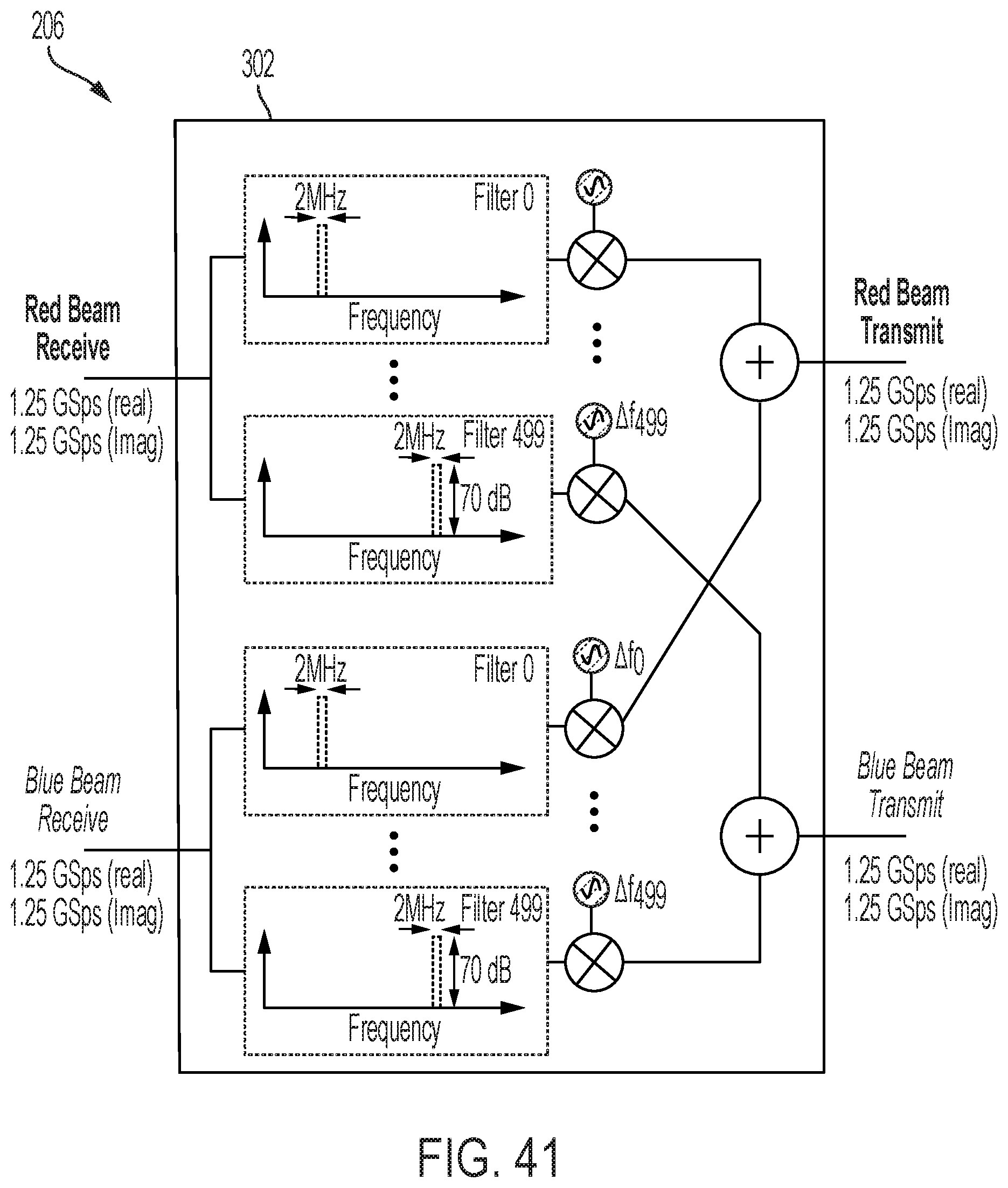
D00032
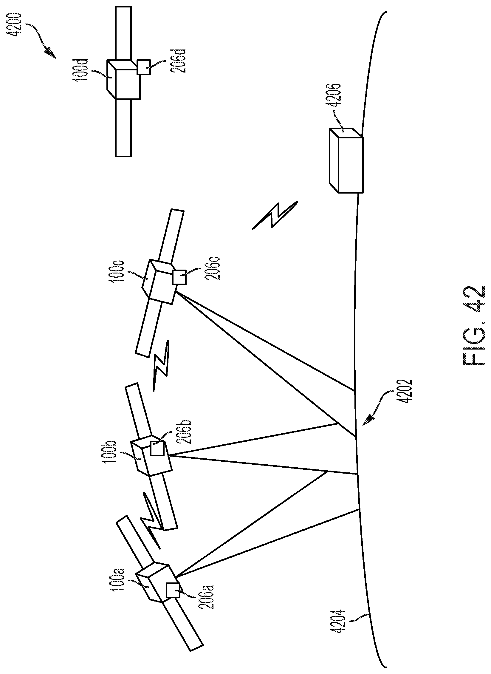
D00033

D00034
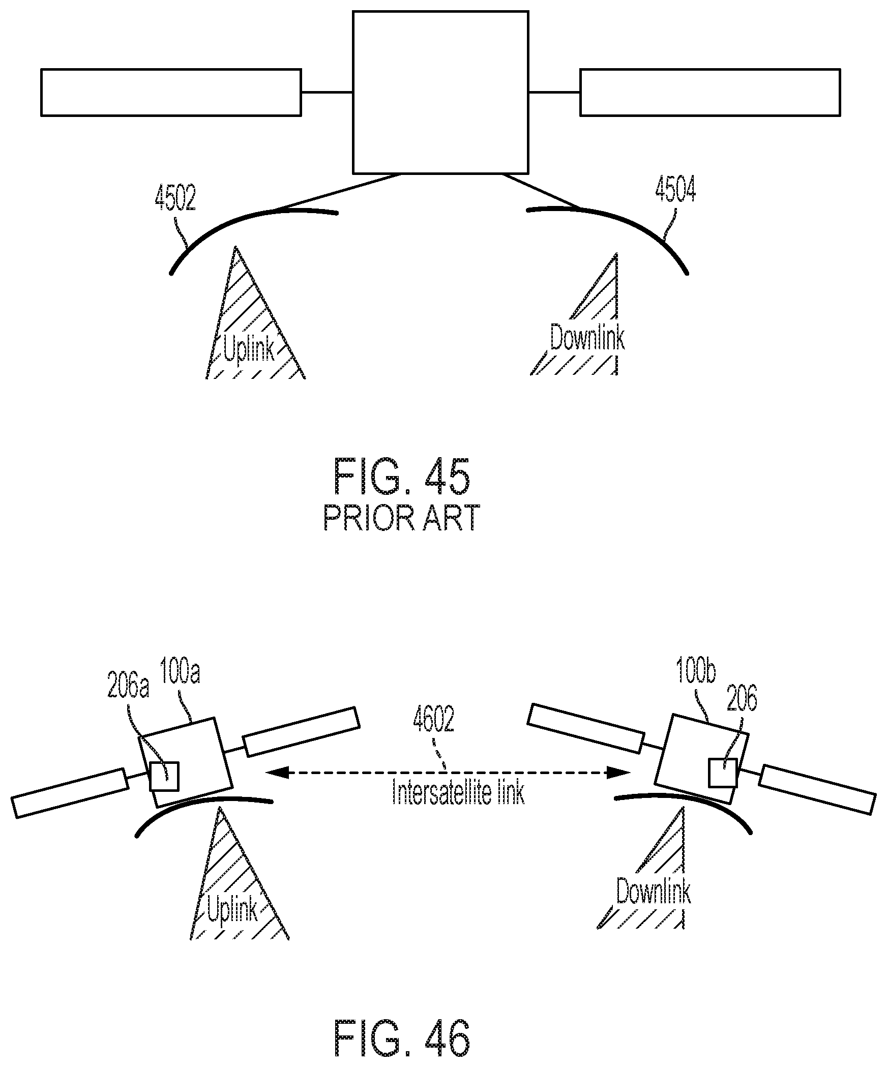
D00035
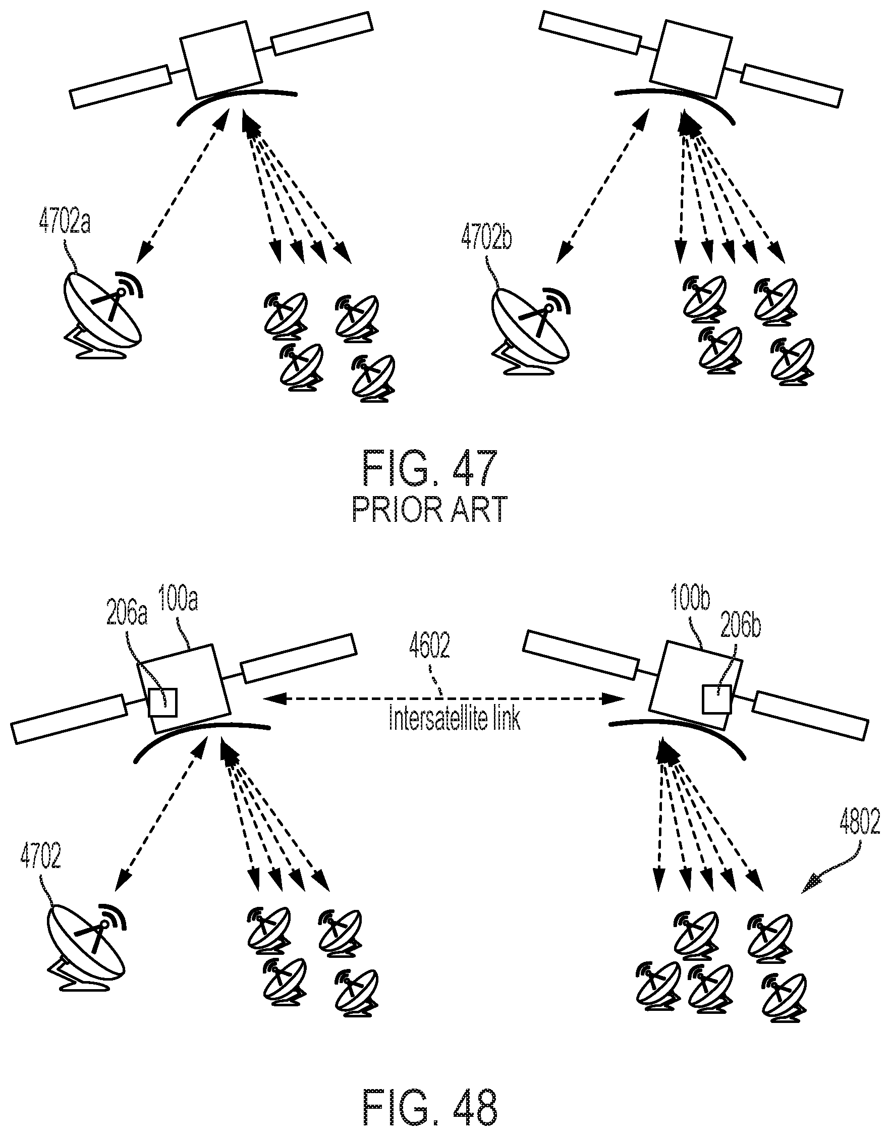
D00036
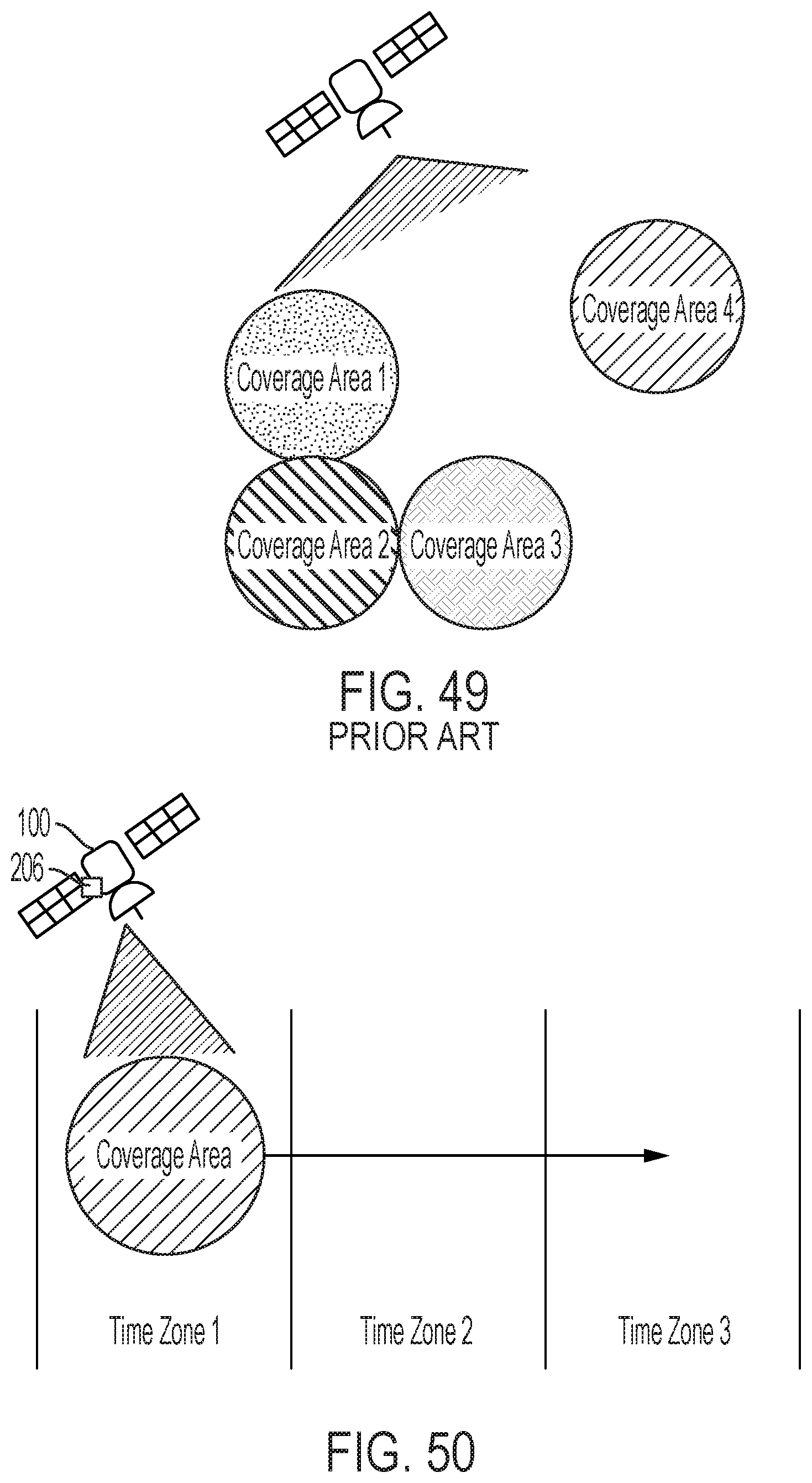
D00037

D00038

D00039

D00040

D00041

D00042
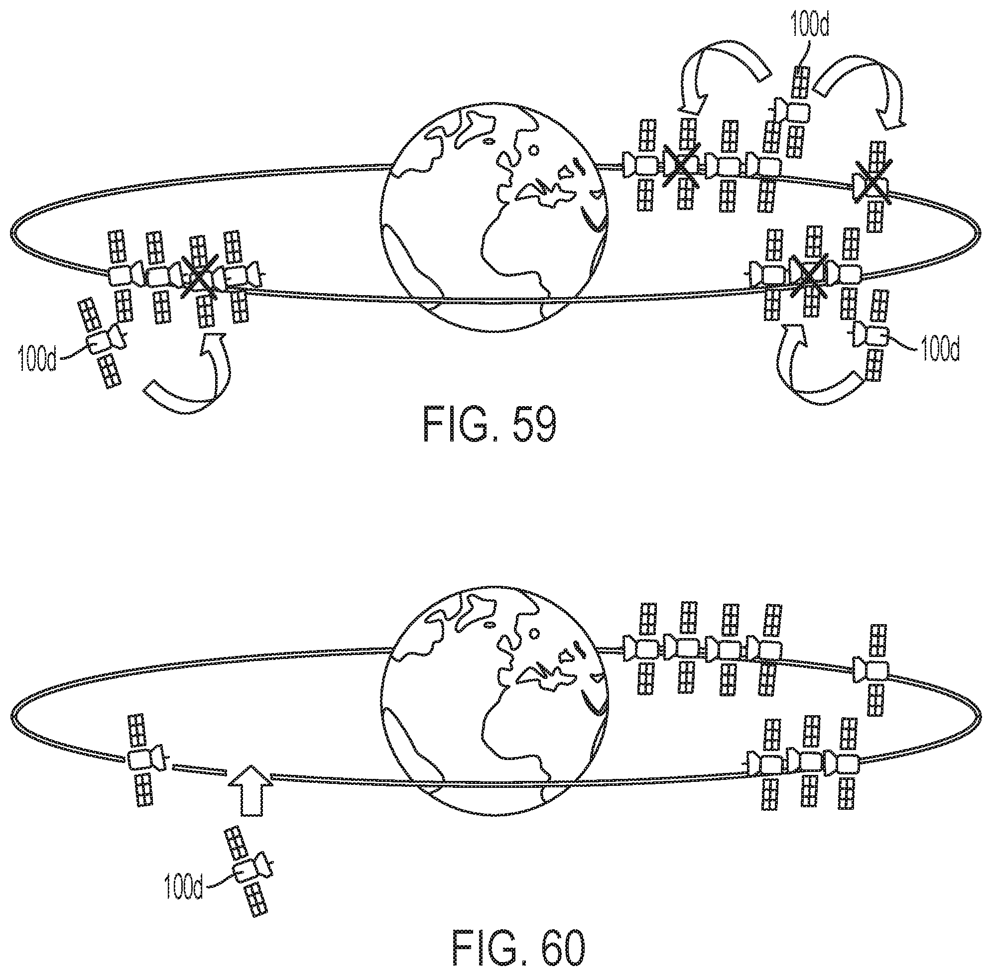
D00043
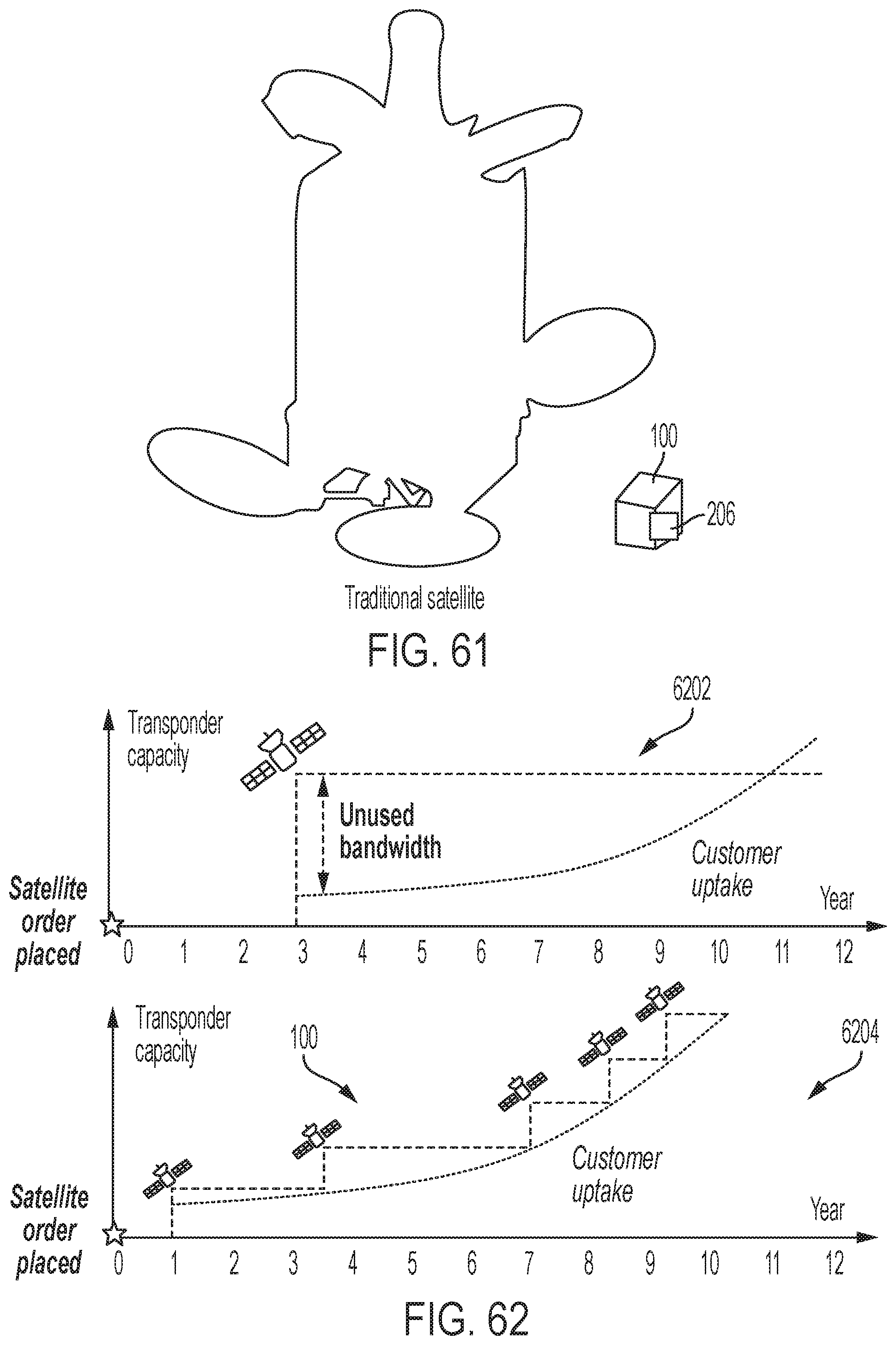
D00044

D00045
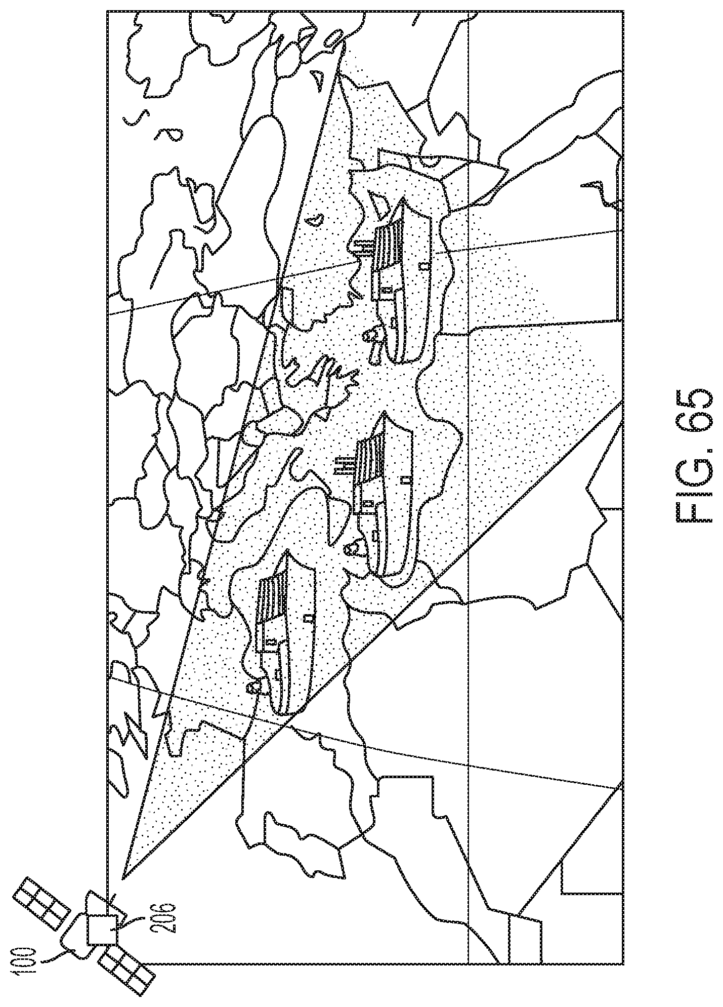
XML
uspto.report is an independent third-party trademark research tool that is not affiliated, endorsed, or sponsored by the United States Patent and Trademark Office (USPTO) or any other governmental organization. The information provided by uspto.report is based on publicly available data at the time of writing and is intended for informational purposes only.
While we strive to provide accurate and up-to-date information, we do not guarantee the accuracy, completeness, reliability, or suitability of the information displayed on this site. The use of this site is at your own risk. Any reliance you place on such information is therefore strictly at your own risk.
All official trademark data, including owner information, should be verified by visiting the official USPTO website at www.uspto.gov. This site is not intended to replace professional legal advice and should not be used as a substitute for consulting with a legal professional who is knowledgeable about trademark law.