Anti-islanding Protection System
FU; Xiaoping ; et al.
U.S. patent application number 16/631627 was filed with the patent office on 2020-06-04 for anti-islanding protection system. The applicant listed for this patent is STATE GRID ZHEJIANG ELECTRIC POWER CO., LTD. TAIZHOU POWER SUPPLY COMPANY STATE GRID CORPORATION OF CHINA. Invention is credited to Mingxu CHEN, Minzhi CHEN, Xiaoping FU, Wenqi HE, Daojian HONG, Zhen HUANG, Guode YING, Chi ZHANG, Dongbo ZHANG, Yuande ZHENG.
| Application Number | 20200176995 16/631627 |
| Document ID | / |
| Family ID | 64819577 |
| Filed Date | 2020-06-04 |


| United States Patent Application | 20200176995 |
| Kind Code | A1 |
| FU; Xiaoping ; et al. | June 4, 2020 |
ANTI-ISLANDING PROTECTION SYSTEM
Abstract
Provided is an anti-islanding protection system. The system is applied to a low-voltage distributed generation resource (DGR) and includes a box, a reverse power protector, a protection module and an output controller. The reverse power protector has an end connected to a first current transformer and has another end connected to the output controller. The reverse power protector is configured to provide reverse power protection for the low-voltage DGR. The output controller has an end connected to the protection module and the reverse power protector and has another end connected to a grid-connection switch of the low-voltage DGR. The output controller is configured to control the grid-connection switch to turn off when reserve power is detected. The protection module has an end connected to a second current transformer and has another end connected to the output controller. The protection module is configured to provide low-frequency protection, over-frequency protection, over-voltage protection and low-voltage protection for the low-voltage DGR.
| Inventors: | FU; Xiaoping; (Zhejiang, CN) ; HE; Wenqi; (Zhejiang, CN) ; ZHANG; Chi; (Zhejiang, CN) ; ZHANG; Dongbo; (Zhejiang, CN) ; HONG; Daojian; (Zhejiang, CN) ; ZHENG; Yuande; (Zhejiang, CN) ; CHEN; Minzhi; (Zhejiang, CN) ; CHEN; Mingxu; (Zhejiang, CN) ; HUANG; Zhen; (Zhejiang, CN) ; YING; Guode; (Zhejiang, CN) | ||||||||||
| Applicant: |
|
||||||||||
|---|---|---|---|---|---|---|---|---|---|---|---|
| Family ID: | 64819577 | ||||||||||
| Appl. No.: | 16/631627 | ||||||||||
| Filed: | February 27, 2019 | ||||||||||
| PCT Filed: | February 27, 2019 | ||||||||||
| PCT NO: | PCT/CN2019/076242 | ||||||||||
| 371 Date: | January 16, 2020 |
| Current U.S. Class: | 1/1 |
| Current CPC Class: | H02J 3/381 20130101; H02H 7/22 20130101; H02B 1/46 20130101; H02B 1/28 20130101; H02J 3/388 20200101 |
| International Class: | H02J 3/38 20060101 H02J003/38; H02H 7/22 20060101 H02H007/22; H02B 1/46 20060101 H02B001/46; H02B 1/28 20060101 H02B001/28 |
Foreign Application Data
| Date | Code | Application Number |
|---|---|---|
| Jul 9, 2018 | CN | 201810743587.3 |
Claims
1. An anti-islanding protection system, applied to a low-voltage distributed generation resource (DGR), wherein the system comprises a box, a reverse power protector, a protection module and an output controller, wherein the reverse power protector, the protection module and the output controller are disposed in the box; the reverse power protector has an end connected to a first current transformer and has another end connected to the output controller, the first current transformer is disposed on a low-voltage side of a transformer of the low-voltage DGR, and the reverse power protector is configured to provide reverse power protection for the low-voltage DGR; the output controller has an end connected to the protection module and the reverse power protector and has another end connected to a grid-connection switch of the low-voltage DGR, the output controller is configured to control the grid-connection switch to turn off when reverse power is detected; and the protection module has an end connected to the output controller and has another end connected to a second current transformer, the second current transformer is connected on an input side of the grid-connection switch of the low-voltage DGR, the protection module is configured to provide low-frequency protection, over-frequency protection, over-voltage protection and low-voltage protection for the low-voltage DGR.
2. The system of claim 1, wherein the protection module comprises a low-frequency protection unit, an over-frequency protection unit, an over-voltage protection unit and a low-voltage protection unit.
3. The system of claim 1, wherein a push rod is disposed in the box, a horizontal transverse plate is disposed above the push rod, the horizontal transverse plate divides the box into a first placement cavity and a second placement cavity; the protection module and the output controller are installed on the horizontal transverse plate and are located in the second placement cavity, the reverse power protector is installed on the horizontal transverse plate and is located in the first placement cavity, and the first placement cavity is provided with a power supply electrically connected to the reverse power protector to supply power to the reverse power protector.
4. The system of claim 1, wherein the reverse power protector is connected to the first current transformer through a plastic optical fiber, the protection module is connected to the second current transformer through a plastic optical fiber, and the output controller is connected to the grid-connection switch through a plastic optical fiber, wherein each plastic optical fiber is provided with a unidirectional switch quantity infrared intrusion optical transmitter and receiver.
5. The system of claim 4, wherein the box is provided with a U-shaped groove for the plastic optical fiber to run through, and the U-shaped groove is provided with a protection layer.
6. The system of claim 5, wherein the box is provided with a box cover, and the box cover is provided with an inclined portion that is inclined downward.
7. The system of claim 6, wherein the box cover is provided with a connecting rod extending into the U-shaped groove, and a compression washer is disposed at a bottom end of the connecting rod and is in contact with the plastic optical fiber.
8. The system of claim 1, wherein the box is provided with a concrete base, and the box is installed on ground along with the concrete base.
Description
CROSS REFERENCE TO RELATED APPLICATIONS
[0001] This application is a United States National Stage Application of co-pending International Patent Application Number PCT/CN2019/076242, filed on Feb. 27, 2019, which claims priority to Chinese patent application No. 201810743587.3 filed Jul. 9, 2018, the contents of which are incorporated herein by reference in their entirety.
[0002] The present application claims the priority of Chinese patent application No. 201810743587.3 filed with Chinese State Intellectual Property Office on Sep. 7, 2018, the content of which is incorporated in the present application by reference in its entirety.
TECHNICAL FIELD
[0003] The present application relates to an anti-islanding protection system.
BACKGROUND
[0004] The anti-islanding protection system is an important protection system for a distributed generation resource (DGR) in a distribution room. The anti-islanding protection is required to implement an active detection method and a passive detection method. The active detection method includes an active frequency drift (AFD) method, disturbance on active power, and disturbance on reactive power. The passive detection method includes detection of voltage phase jumps and detection of frequency changes. An islanding protection trip outlet is generally connected to a grid-connection circuit breaker. When an islanding phenomenon occurs, the grid-connection circuit breaker is cut off, so the anti-islanding protection system is required to have a capability of accurately detecting the voltage and frequency of a grid-connection point. When the voltage and frequency fluctuate and are larger than a determined range, the trip outlet acts to turn off the grid-connection switch. However, the anti-islanding protection system installed at a boundary point of the DGR at present cannot implement 100% anti-islanding operation. This leaves potential safety hazards for scheduled outage maintenance of devices at a power grid side.
SUMMARY
[0005] The following is a summary of the subject matter described herein in detail. This summary is not intended to limit the scope of the claims.
[0006] The application provides an anti-islanding protection system, so as to avoid the situation that the related anti-islanding protection system leaves potential safety hazards during outage maintenance at the power grid side. The present application adopts the technical solution described below. Provided is an anti-islanding protection system, which is applied to a low-voltage DGR and includes a box, a reverse power protector, a protection module and an output controller. The reverse power protector, the protection module and the output controller are all disposed in the box. The reverse power protector has an end connected to a first current transformer and has another end connected to the output controller. The first current transformer is installed on a low-voltage side of a transformer of the low-voltage DGR, and the reverse power protector is configured to provide reverse power protection for the low-voltage DGR. The output controller has an end connected to the protection module and the reverse power protector and has another end connected to a grid-connection switch of the low-voltage DGR. The output controller is configured to control the grid-connection switch to turn off when reverse power is detected. The protection module has an end connected to the output controller and has another end connected to a second current transformer. The second current transformer is connected on an input side of the grid-connection switch of the low-voltage DGR. The protection module is configured to provide low-frequency protection, over-frequency protection, over-voltage protection and low-voltage protection for the low-voltage DGR.
[0007] Other aspects can be understood after the drawings and the detailed description are read and understood.
BRIEF DESCRIPTION OF DRAWINGS
[0008] The present application will be further described with reference to the drawings.
[0009] FIG. 1 is a structural diagram of an anti-islanding protection system according to an embodiment of the present application.
[0010] FIG. 2 is a structural diagram of an anti-islanding protection system installed on a low-voltage distributed generation resource according to an embodiment of the present application.
LIST OF REFERENCE NUMBERS:
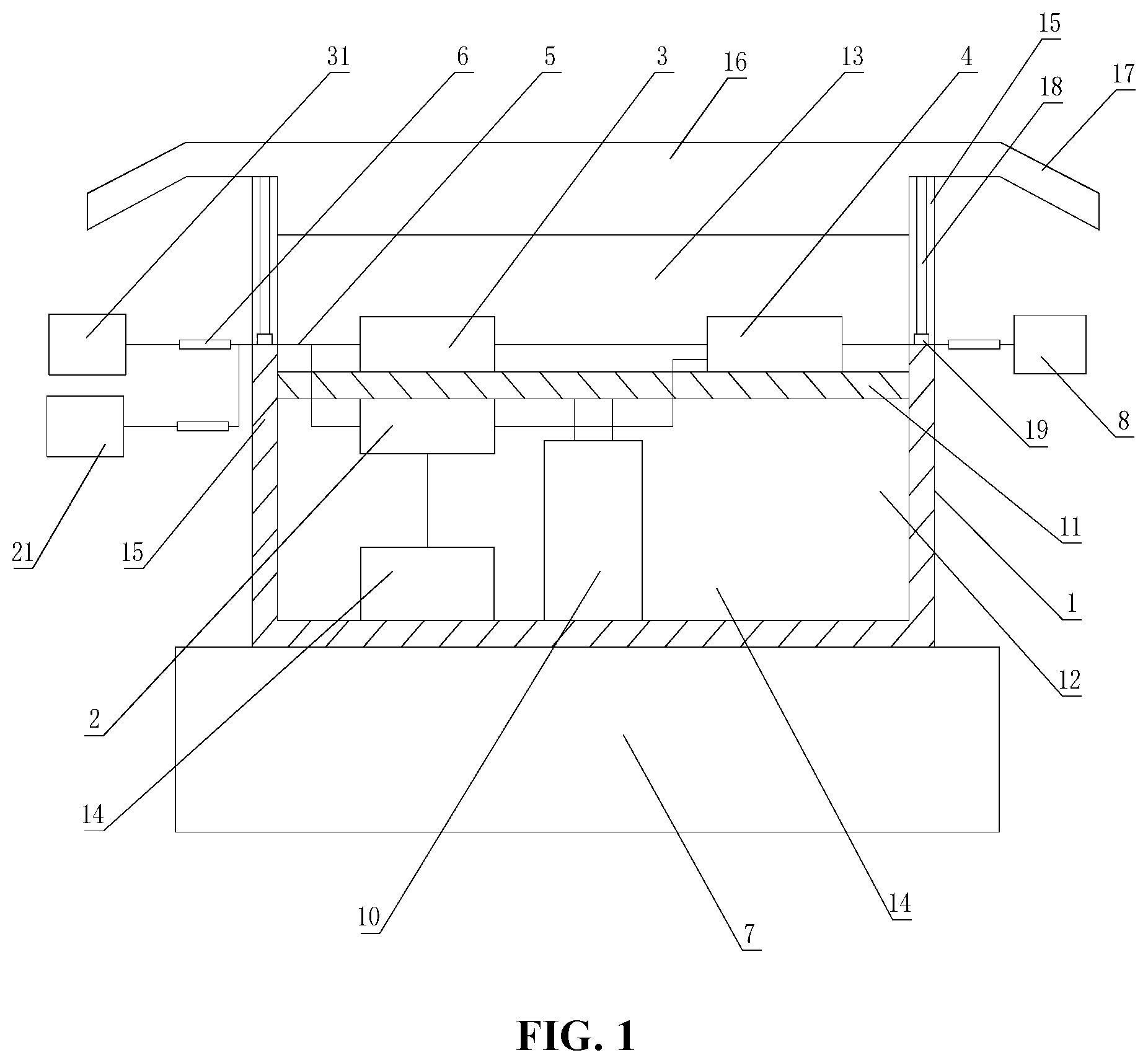
[0011] 1: box; 10: push rod; 11: horizontal transverse plate; 12: first placement cavity; 13: second placement cavity; 14: power supply; 15: U-shaped groove; 16: box cover; 17: inclined portion; 18: connecting rod; 19: compression washer; 20: reverse power protector; 21: first current transformer; 3: protection module; 31: second current transformer; 4: output controller; 5: plastic optical fiber; 6: unidirectional switch quantity infrared intrusion optical transmitter; 7: concrete base; 8: grid-connection switch.
DETAILED DESCRIPTION
[0012] As shown in FIGS. 1 and 2, a zero-blind-area anti-islanding protection system of low-voltage distributed power supply includes a box 1, a reverse power protector 2, a protection module 3 and an output controller 4. The reverse power protector 2, the protection module 3 and the output controller 4 are all disposed in the box 1. The protection module 3 includes a low-frequency protection unit, an over-frequency protection unit, an over-voltage protection unit and a low-voltage protection unit. When the current has low frequency, over frequency, low voltage or over voltage, a forcing switch-off command may be immediately delivered to a grid-connection switch of the low-voltage DGR through the output controller, thereby ensuring the normal operation of the line. The reverse power protector 2 has an end connected to a first current transformer 21. The first current transformer 21 is installed on a low-voltage side of a transformer of a low-voltage DGR 14. The reverse power protector 2 has another end connected to the output controller 4. The protection module 3 has an end connected to a second current transformer 31. The second current transformer 31 is installed on an input side of the grid-connection switch 8 of the low-voltage DGR 14. The protection module 3 has another end connected to the output controller 4. The output controller 4 is connected to the grid-connection switch 8 of the low-voltage DGR 14. The current of the low-voltage side of the transformer is detected through the first current transformer connected to the reverse power protector. When a reverse current is detected, a forcing switch-off command may be immediately delivered to the grid-connection switch of the low-voltage DGR through the output controller, thus completely ensuring no existence of islanding, ensuring that the DGR will not return high-voltage power to the 10 KV line through the transformer, ensuring the safety of the repair or maintenance personnel, and avoiding the occurrence of mass casualties.
[0013] In the related art, the anti-islanding protection system is installed at the grid-connection switch to control the grid-connection switch to turn off, so that the protection function is implemented. The DGR user is capable of install the system. The anti-islanding protection system in the embodiments of the present application is installed in a distribution room by an electric power company. The system not only has the conventional protection function of the anti-islanding system, but also has the function of collecting values of the voltage and current at a low-voltage main switch of a distribution transformer to determine the reverse power, thereby implementing the reverse power protection, and ensuring the operation safety of the power grid and the safety of repair and maintenance personnel on the whole.
[0014] A push rod 10 is disposed in the box 1. A horizontal transverse plate 11 is disposed above the push rod 10. The horizontal transverse plate 11 divides the box 1 into a first placement cavity 12 and a second placement cavity 13. The protection module 3 and the output controller 4 are installed on the horizontal transverse plate 11 and are located in the second placement cavity 13. The reverse power protector 2 is installed on the horizontal transverse plate 11 and is located in the first placement cavity 12. The first placement cavity is provided with a power supply 14 electrically connected to the reverse power protector. The setting of horizontal transverse plate can ensure the unified installation of reverse power protector, the protection module and the output controller, optimizes the inner space of the box, benefits the placement of the power supply, saves the installation costs, and can adapt to different installation environment. The setting of the power supply can ensure the continuous operation of the reverse power protector, and ensure the stable operation of the anti-islanding protection system. By setting the horizontal transverse plate on the push rod, the horizontal transverse plate is released through the extension of the push rod, which benefits the maintenance personnel to maintain the system, and improves maintenance efficiency and maintenance quality. In addition, the reverse power protector 2 can normally operate when the voltage of the power grid changes within the range of .+-.10% of a rated voltage and the frequency changes within the range of .+-.5% of a rated frequency. The power supply uses a two-phase power supply of 400V 50 Hz/60 Hz alternating current (AC), and a rated input current is 5 A two-phase AC current. When a reverse power value of a set running in parallel reaches 3% to 15% of rated power and the delay is 3 to 10 seconds, a reverse power relay works. In order to reduce the installation area of the protection module 3, the protection module 3 in this embodiment further includes a cassette. The low-frequency protection unit, the over-frequency protection unit, the over-voltage protection unit and the low-voltage protection unit are all disposed on the cassette.
[0015] The reverse power protector 2 is connected to the first current transformer 21 through a plastic optical fiber 5, the protection module 3 is connected to the second current transformer 31 through a plastic optical fiber 5, and the output controller 4 is connected to the grid-connection switch 8 through a plastic optical fiber 5. The plastic optical fiber 5 is provided with a unidirectional switch quantity infrared intrusion optical transmitter and receiver 6. The plastic optical fiber 5 and the unidirectional switch quantity infrared intrusion optical transmitter and receiver 6 can improve the speed of anti-islanding protection.
[0016] The box is provided with a U-shaped groove 15 for the plastic optical fiber to run through, and the U-shaped groove is provided with a protection layer. The U-shaped groove can ensure that the plastic optical fiber is quickly installed on the box, optimize the wiring of the plastic optical fiber, and reduce the length of the plastic optical fiber. The setting of the protective layer can ensure the installation quality of the plastic optical fiber, and reduce the damage to the plastic optical fiber.
[0017] In addition, the box 1 is provided with a box cover 16, and the box cover 16 is provided with an inclined portion 17 that is inclined downward. The setting of the box cover 16 can implement sealing of the box 1, which benefits the quick installation and maintenance of the reverse power protector 2, the protection module 3 and the output controller 4. The setting of the inclined portion 17 can prevent rainwater from entering the box 1, and improve the safety performance during operation of the anti-islanding protection system.
[0018] The box cover 16 is provided with a connecting rod 18 extending into the U-shaped groove, and a compression washer 19 is disposed at a bottom end of the connecting rod 18 and is in contact with the plastic optical fiber. During the use, the sealing of the U-shaped groove is implemented through the connecting rod extending into the U-shaped groove, which avoids dust or debris to get into the box. Moreover, the setting of the compression washer can ensure the stability of the plastic optical fiber, avoid rotation and axial shaking of the plastic optical fiber, and benefit fixed installation of the plastic optical fiber.
[0019] The box 1 is provided with a concrete base 7. The box 1 is installed on the ground along with the concrete base 7. The concrete base 7 can ensure that the box 1 can be steadily installed on the ground and installed near a user equipment of the low-voltage DGR 14, which can further improve the safety performance during operation of the anti-islanding protection system.
TECHNICAL FIELD
[0020] The present application relates to an anti-islanding protection system.
BACKGROUND
[0021] The anti-islanding protection system is an important protection system for a distributed generation resource (DGR) in a distribution room. The anti-islanding protection is required to implement an active detection method and a passive detection method. The active detection method includes an active frequency drift (AFD) method, disturbance on active power, and disturbance on reactive power. The passive detection method includes detection of voltage phase jumps and detection of frequency changes. An islanding protection trip outlet is generally connected to a grid-connection circuit breaker. When an islanding phenomenon occurs, the grid-connection circuit breaker is cut off, so the anti-islanding protection system is required to have a capability of accurately detecting the voltage and frequency of a grid-connection point.
[0022] When the voltage and frequency fluctuate and are larger than a determined range, the trip outlet acts to turn off the grid-connection switch. However, the anti-islanding protection system installed at a boundary point of the DGR at present cannot implement 100% anti-islanding operation. This leaves potential safety hazards for scheduled outage maintenance of devices at a power grid side.
SUMMARY
[0023] The following is a summary of the subject matter described herein in detail. This summary is not intended to limit the scope of the claims.
[0024] The application provides an anti-islanding protection system, so as to avoid the situation that the related anti-islanding protection system leaves potential safety hazards during outage maintenance at the power grid side.
[0025] The present application adopts the technical solution described below. Provided is an anti-islanding protection system, which is applied to a low-voltage DGR and includes a box, a reverse power protector, a protection module and an output controller. The reverse power protector, the protection module and the output controller are all disposed in the box. The reverse power protector has an end connected to a first current transformer and has another end connected to the output controller. The first current transformer is installed on a low-voltage side of a transformer of the low-voltage DGR, and the reverse power protector is configured to provide reverse power protection for the low-voltage DGR. The output controller has an end connected to the protection module and the reverse power protector and has another end connected to a grid-connection switch of the low-voltage DGR. The output controller is configured to control the grid-connection switch to turn off when reverse power is detected. The protection module has an end connected to the output controller and has another end connected to a second current transformer. The second current transformer is connected on an input side of the grid-connection switch of the low-voltage DGR. The protection module is configured to provide low-frequency protection, over-frequency protection, over-voltage protection and low-voltage protection for the low-voltage DGR.
[0026] Other aspects can be understood after the drawings and the detailed description are read and understood.
BRIEF DESCRIPTION OF DRAWINGS
[0027] The present application will be further described with reference to the drawings.
[0028] FIG. 1 is a structural diagram of an anti-islanding protection system according to an embodiment of the present application.
[0029] FIG. 2 is a structural diagram of an anti-islanding protection system installed on a low-voltage distributed generation resource according to an embodiment of the present application.
LIST OF REFERENCE NUMBERS:
[0030] 1: box; 10: push rod; 11: horizontal transverse plate; 12: first placement cavity; 13: second placement cavity; 14: power supply; 15: U-shaped groove; 16: box cover; 17: inclined portion; 18: connecting rod; 19: compression washer; 2: reverse power protector; 21: first current transformer; 3: protection module; 31: second current transformer; 4: output controller; 5: plastic optical fiber; 6: unidirectional switch quantity infrared intrusion optical transmitter; 7: concrete base; 8: grid-connection switch.
DETAILED DESCRIPTION
[0031] As shown in FIGS. 1 and 2, a zero-blind-area anti-islanding protection system of low-voltage distributed power supply includes a box 1, a reverse power protector 2, a protection module 3 and an output controller 4. The reverse power protector 2, the protection module 3 and the output controller 4 are all disposed in the box 1. The protection module 3 includes a low-frequency protection unit, an over-frequency protection unit, an over-voltage protection unit and a low-voltage protection unit. When the current has low frequency, over frequency, low voltage or over voltage, a forcing switch-off command may be immediately delivered to a grid-connection switch of the low-voltage DGR through the output controller, thereby ensuring the normal operation of the line. The reverse power protector 2 has an end connected to a first current transformer 21. The first current transformer 21 is installed on a low-voltage side of a transformer of a low-voltage DGR 14. The reverse power protector 2 has another end connected to the output controller 4. The protection module 3 has an end connected to a second current transformer 31. The second current transformer 31 is installed on an input side of the grid-connection switch 8 of the low-voltage DGR 14. The protection module 3 has another end connected to the output controller 4. The output controller 4 is connected to the grid-connection switch 8 of the low-voltage DGR 14. The current of the low-voltage side of the transformer is detected through the first current transformer connected to the reverse power protector. When a reverse current is detected, a forcing switch-off command may be immediately delivered to the grid-connection switch of the low-voltage DGR through the output controller, thus completely ensuring no existence of islanding, ensuring that the DGR will not return high-voltage power to the 10 KV line through the transformer, ensuring the safety of the repair or maintenance personnel, and avoiding the occurrence of mass casualties.
[0032] In the related art, the anti-islanding protection system is installed at the grid-connection switch to control the grid-connection switch to turn off, so that the protection function is implemented. The DGR user is capable of install the system. The anti-islanding protection system in the embodiments of the present application is installed in a distribution room by an electric power company. The system not only has the conventional protection function of the anti-islanding system, but also has the function of collecting values of the voltage and current at a low-voltage main switch of a distribution transformer to determine the reverse power, thereby implementing the reverse power protection, and ensuring the operation safety of the power grid and the safety of repair and maintenance personnel on the whole.
[0033] A push rod 10 is disposed in the box 1. A horizontal transverse plate 11 is disposed above the push rod 10. The horizontal transverse plate 11 divides the box 1 into a first placement cavity 12 and a second placement cavity 13. The protection module 3 and the output controller 4 are installed on the horizontal transverse plate 11 and are located in the second placement cavity 13. The reverse power protector 2 is installed on the horizontal transverse plate 11 and is located in the first placement cavity 12. The first placement cavity is provided with a power supply 14 electrically connected to the reverse power protector. The setting of horizontal transverse plate can ensure the unified installation of reverse power protector, the protection module and the output controller, optimizes the inner space of the box, benefits the placement of the power supply, saves the installation costs, and can adapt to different installation environment. The setting of the power supply can ensure the continuous operation of the reverse power protector, and ensure the stable operation of the anti-islanding protection system. By setting the horizontal transverse plate on the push rod, the horizontal transverse plate is released through the extension of the push rod, which benefits the maintenance personnel to maintain the system, and improves maintenance efficiency and maintenance quality. In addition, the reverse power protector 2 can normally operate when the voltage of the power grid changes within the range of .+-.10% of a rated voltage and the frequency changes within the range of .+-.5% of a rated frequency. The power supply uses a two-phase power supply of 400V 50 Hz/60 Hz alternating current (AC), and a rated input current is 5 A two-phase AC current. When a reverse power value of a set running in parallel reaches 3% to 15% of rated power and the delay is 3 to 10 seconds, a reverse power relay works. In order to reduce the installation area of the protection module 3, the protection module 3 in this embodiment further includes a cassette. The low-frequency protection unit, the over-frequency protection unit, the over-voltage protection unit and the low-voltage protection unit are all disposed on the cassette.
[0034] The reverse power protector 2 is connected to the first current transformer 21 through a plastic optical fiber 5, the protection module 3 is connected to the second current transformer 31 through a plastic optical fiber 5, and the output controller 4 is connected to the grid-connection switch 8 through a plastic optical fiber 5. The plastic optical fiber 5 is provided with a unidirectional switch quantity infrared intrusion optical transmitter and receiver 6. The plastic optical fiber 5 and the unidirectional switch quantity infrared intrusion optical transmitter and receiver 6 can improve the speed of anti-islanding protection.
[0035] The box is provided with a U-shaped groove 15 for the plastic optical fiber to run through, and the U-shaped groove is provided with a protection layer. The U-shaped groove can ensure that the plastic optical fiber is quickly installed on the box, optimize the wiring of the plastic optical fiber, and reduce the length of the plastic optical fiber. The setting of the protective layer can ensure the installation quality of the plastic optical fiber, and reduce the damage to the plastic optical fiber.
[0036] In addition, the box 1 is provided with a box cover 16, and the box cover 16 is provided with an inclined portion 17 that is inclined downward. The setting of the box cover 16 can implement sealing of the box 1, which benefits the quick installation and maintenance of the reverse power protector 2, the protection module 3 and the output controller 4. The setting of the inclined portion 17 can prevent rainwater from entering the box 1, and improve the safety performance during operation of the anti-islanding protection system.
[0037] The box cover 16 is provided with a connecting rod 18 extending into the U-shaped groove, and a compression washer 19 is disposed at a bottom end of the connecting rod 18 and is in contact with the plastic optical fiber. During the use, the sealing of the U-shaped groove is implemented through the connecting rod extending into the U-shaped groove, which avoids dust or debris to get into the box. Moreover, the setting of the compression washer can ensure the stability of the plastic optical fiber, avoid rotation and axial shaking of the plastic optical fiber, and benefit fixed installation of the plastic optical fiber.
[0038] The box 1 is provided with a concrete base 7. The box 1 is installed on the ground along with the concrete base 7. The concrete base 7 can ensure that the box 1 can be steadily installed on the ground and installed near a user equipment of the low-voltage DGR 14, which can further improve the safety performance during operation of the anti-islanding protection system.
* * * * *
D00000
D00001
D00002
XML
uspto.report is an independent third-party trademark research tool that is not affiliated, endorsed, or sponsored by the United States Patent and Trademark Office (USPTO) or any other governmental organization. The information provided by uspto.report is based on publicly available data at the time of writing and is intended for informational purposes only.
While we strive to provide accurate and up-to-date information, we do not guarantee the accuracy, completeness, reliability, or suitability of the information displayed on this site. The use of this site is at your own risk. Any reliance you place on such information is therefore strictly at your own risk.
All official trademark data, including owner information, should be verified by visiting the official USPTO website at www.uspto.gov. This site is not intended to replace professional legal advice and should not be used as a substitute for consulting with a legal professional who is knowledgeable about trademark law.