Electrical Connector For Fuel Cell Stack Voltage Monitoring
MUNTHE; Stefan ; et al.
U.S. patent application number 16/623451 was filed with the patent office on 2020-06-04 for electrical connector for fuel cell stack voltage monitoring. This patent application is currently assigned to POWERCELL SWEDEN AB. The applicant listed for this patent is POWERCELL SWEDEN AB. Invention is credited to Mattias HOLMBERG, Stefan MUNTHE.
| Application Number | 20200176792 16/623451 |
| Document ID | / |
| Family ID | 62778973 |
| Filed Date | 2020-06-04 |


| United States Patent Application | 20200176792 |
| Kind Code | A1 |
| MUNTHE; Stefan ; et al. | June 4, 2020 |
ELECTRICAL CONNECTOR FOR FUEL CELL STACK VOLTAGE MONITORING
Abstract
An electric connector for fuel cell stack voltage monitoring includes at least two separate units, each unit including a plurality of pins, each pin being adapted to contact a plate of the fuel cell stack for monitoring a fuel cell stack voltage. The first pin of each unit is adapted to provide a measurement of a reference voltage.
| Inventors: | MUNTHE; Stefan; (Vastra Frolunda, SE) ; HOLMBERG; Mattias; (Goteborg, SE) | ||||||||||
| Applicant: |
|
||||||||||
|---|---|---|---|---|---|---|---|---|---|---|---|
| Assignee: | POWERCELL SWEDEN AB 418 34 Goteborg SE |
||||||||||
| Family ID: | 62778973 | ||||||||||
| Appl. No.: | 16/623451 | ||||||||||
| Filed: | June 8, 2018 | ||||||||||
| PCT Filed: | June 8, 2018 | ||||||||||
| PCT NO: | PCT/SE2018/050598 | ||||||||||
| 371 Date: | December 17, 2019 |
| Current U.S. Class: | 1/1 |
| Current CPC Class: | G01R 31/3835 20190101; H01M 8/04559 20130101; H01R 13/6683 20130101; H01R 2201/20 20130101; H01R 31/005 20130101; G01R 31/396 20190101; H01M 8/04552 20130101; H01M 8/0258 20130101 |
| International Class: | H01M 8/04537 20060101 H01M008/04537; H01M 8/0258 20060101 H01M008/0258; G01R 31/3835 20060101 G01R031/3835; G01R 31/396 20060101 G01R031/396; H01R 31/00 20060101 H01R031/00 |
Foreign Application Data
| Date | Code | Application Number |
|---|---|---|
| Jun 20, 2017 | SE | 1750786-4 |
Claims
1. An electric connector for fuel cell stack voltage monitoring comprising at least two separate units, each unit comprising a plurality of pins, each pin being adapted to contact a plate of the fuel cell stack for monitoring a fuel cell stack voltage, wherein the first pin of each unit is adapted to provide a measurement of a reference voltage.
2. The electric connector according to claim 1, wherein each unit is adapted to be attached to the fuel cell stack using a friction fit connection.
3. The electric connector according to claim 1, further comprising a plug which is connected to the at least two units and which is adapted to connect the electric connector with a cell voltage measurement system.
4. The electric connector according to claim 1, further comprising at least two plugs each plug being connected to one of the at least two units and being adapted to connect the electric connector with a cell voltage measurement system.
5. The electric connector according to claim 1, wherein each unit and/or the plug is provided on a rigid holding element, such as a plastic plate or a printed wire board.
6. The electric connector according to claim 3, wherein the plug and the at least two units are connected via conductive paths bonded into a flexible plastic material.
7. The electric connector according to claim 3, wherein the plug is attachable to a holding element of the fuel cell stack, in particular to a housing element of the fuel cell stack, using attaching elements providing a variable positioning of the plug.
8. The electric connector according to claim 1, wherein the pins of one unit are arranged in at least two rows.
9. The electric connector according to claim 1, wherein at least the first unit comprises a protrusion on which the first pin is arranged and wherein at least the second unit comprises a recess being correspondingly formed opposed to the protrusion, wherein the protrusion of the first unit and the recess of the second unit are corresponding.
10. An electric connector arrangement comprising at least two electric connectors according to claim 1.
11. A fuel cell stack arrangement comprising a fuel cell stack with at least two fuel cell units comprising a fluid flow field plate, in particular a bipolar plate, and a membrane electrode assembly, and at least one electric connector according to claim 1, wherein, in an assembled state, the pins of the at least two units are arranged to contact the fluid flow field plates of the at least two fuel cell units for monitoring a fuel cell stack voltage.
12. A method for fuel cell stack voltage monitoring, comprising arranging an electric connector according to claim 1 to a fuel cell stack according to claim 9 by contacting the pins of the at least two units to the fluid flow field plates of the fuel cell stack, wherein the pins of one of the units connect subsequently arranged fluid flow field plates, and using the first pin of the units for determining a reference voltage for voltage monitoring of the fluid flow field plates connected by the units.
Description
BACKGROUND AND SUMMARY
[0001] The present invention relates to an electric connector for fuel cell stack voltage monitoring. Further, the present invention relates to an electric connector arrangement comprising at least two of these electric connectors. Moreover, the present invention relates to a fuel cell stack arrangement comprising such an electric connector. Furthermore, the present invention relates to a method for fuel cell stack voltage monitoring.
[0002] A fuel cell stack is usually formed by stacking a large number of unit cells into numerous layers. Each of the unit cells comprises at least a membrane electrode assembly (MEA) having an ion exchange membrane sandwiched between an anode and a cathode, and fluid flow field plates on both outer sides of the MEA. Through the fluid flow field plates, hydrogen fuel and an oxidizing agent are supplied to the MEA, which generates electric power.
[0003] For such a fuel cell stack, management of the power generation state of each unit cell is necessary in order to control the amounts of supplied hydrogen and oxygen and/or to find a broken or malfunctioning unit fuel cell. To enable such management, the generated voltage for each unit cell is monitored and the control is carried out based on the monitored voltage.
[0004] For monitoring the fuel cell stack voltage, fluid flow field plates are connected by electrical connectors, which arc adapted to electrically contact the fluid flow field plates.
[0005] From the state of the art, e.g. US 2003/054220 a comb-shaped electric contact element is known, which is supported on a support structure and whose teeth are adapted to abut to the bipolar plates, whereby the electric contact is established. The disadvantage of such a connector is manifold. Firstly, the used bipolar plates must have a certain minimum thickness for allowing an electrical contact to be established by adjoining bipolar plate and electric contact element. Secondly, the electric connector easily detaches from the bipolar plates, so that additional fixing elements are required for fixing the electric connector to the fuel cell stack. A further problem is that the distances between the teeth of the electric contact must be carefully designed in order to fit to the fuel cell stack. Thereby, only minimal manufacturing tolerances are allowed, which in turn results in a costly and time-consuming manufacturing process.
[0006] Further, for monitoring the voltages of a fuel cell stack, each plate needs to be contacted as the voltage of one plate is measured in comparison with the voltage of the previous plate. Thus, plates may not be easily skipped. In case a plate is skipped (which may be realized by using two or more electric connectors, wherein only one plate may be skipped) or if two electric connectors are used without skipping plates, the second electric connector has to be coupled via a jumper to the first electric connector so that the reference to the previous plate remains established. If more than one plate is skipped, the voltage is measured over more plates. However, this causes a wrong measurement as a correct voltage may be measured only with reference to the previous plate.
[0007] It is therefore desirable to provide an electric connector, which can be easily fixed to the fuel cell stack and allows for a flexible monitoring of the fuel cell stack voltage.
[0008] In die following, an electric connector is disclosed. The electric connector comprises at least two separate units, each unit comprising a plurality of pins, each pin being adapted to contact a plate of the fuel cell stack for monitoring a fuel cell stack voltage. The first pin of each unit is adapted to provide a measurement of a reference voltage.
[0009] Each unit of the electric connector comprises a plurality of pins (also called contact pins), wherein one of these pins is used for providing a reference voltage. This means that each pin except of the first pin may measure a voltage with respect to the reference voltage provided by the first pin of each unit. Accordingly, it is therefore possible to skip as many cells or plates as desired as each unit provides its own reference voltage and the reference voltage may thus be provided not only at the first plate of a fuel cell stack but also at any other plate which is contacted by the first pin. This provides a very variable usage of the electric connector as also more than one plate may be skipped.
[0010] If the first pin of the second unit and the last pin of the first unit contact the same plate, each pin of the second unit, except of the first pin, may measure a voltage with respect to the reference voltage provided by the first pin of the first unit. This means that in this case each pin of each unit except of the first pin of the first unit and the first pin of the second unit may measure a voltage with respect to the reference voltage provided by the first pin of the first unit without the need for using jumpers.
[0011] The variable usage of the electric connector may be further enhanced when each unit comprises an adjustable number of pins. In such an embodiment, the number of pins may be adapted to the number of plates. Each unit may comprise a different number of pins.
[0012] According to an embodiment, each unit is adapted to be attached to the fuel cell stack using a friction fit connection. This means that the pins are inserted into the fuel cell stack and the electric connector can be hold in the fuel cell stack by friction between the pins and the plates. Additional holding means are not necessary.
[0013] According to a further embodiment, the electric connector comprises a plug which is connected to the at least two units and which is adapted to connect the electric connector with a cell voltage measurement system. The plug may be any kind of standard plug which is suitable to be connected to a cell voltage measurement system on the one side and the units of the electric connector on the other side. In this embodiment, the at least two units are connected to the same plug.
[0014] In another embodiment, the electric connector comprises at least two plugs, each plug being connected to one of the at least two units. This means that each plug is connected to one of the units on the one side and to the cell voltage measurement system on the other side.
[0015] According to a further embodiment, each unit and/or plug is provided on a rigid holding element, such as a plastic plate or a printed wire board. This means that the pins of each unit are attached to a rigid holding element. The length of each unit, and thus also the number of pins, may be adjusted by cutting the rigid holding element into length. The overall assembly of electric connector and printed circuit board may thus be insensitive to fine tolerances. Further, the printed wire board may support heat expansion.
[0016] As the first pin of each unit may be defined and thus it may be determined which pin provides a reference voltage, it is even possible to separate one unit into two or more sub-units by cutting the rigid holding element into two or more parts. This may allow a finer resolution to a possible total cell number. If this is the case, the first pin of each sub-unit may be determined for providing a reference voltage.
[0017] According to a further embodiment, the plug and the at least two units are connected via conductive paths bonded into a flexible plastic material. As a flexible plastic material is used, a variable positioning of the units and the plug with respect to each other may be achieved as the connection may be easily bent.
[0018] Further, when the units are cut and separated into several sub-units, the flexible plastic material may also be cut into several connections so that the conductive paths of leading to one sub-unit are separated from the conductive paths leading to another sub-unit. Due to the flexible plastic material, it may be possible to switch the location of contact pins to facilitate a variety of stack sizes.
[0019] The plug may be adapted to provide an analog signal, i.e. a signal from the contact pins, to the cell voltage measurement system. In the cell voltage measurement system, the analog signal may be analyzed and a result of the analyzation may be provided as a digital signal to any further processing or computing unit. The analog signal as provided via the plugs may be transmitted via a bus or the like to the cell voltage measurement system. Thus, the analyzation and further processing, which is carried out in the cell voltage measurement system may be located remote. This provides the advantage that no space for the cell voltage measurement is required in the fuel cell stack. Further, the heat generation may be reduced at the fuel cell stack.
[0020] According to a further embodiment, the plug is attachable to a holding element of the fuel cell stack, in particular to a housing element of the fuel cell stack, using attaching elements providing a variable positioning of the plug. The attaching elements may be screws and or clips. The housing may be for example a touch protection of the fuel cell stack or a holder of the touch protection. The touch protection may be an extruded plastic profile or profiled holding board. The material used for the housing may be made of a plastic material, in particular reinforced plastics such as fiber-reinforced plastic.
[0021] The attaching elements may provide a variable positioning of the plug as they may be attached to the holding element at variable positions. This may be realized for example using self-tapping screws which can be attached to the housing without a need for holes.
[0022] According to a further embodiment, the pins of one unit are arranged in at least two rows. This means that two consecutive pins are arranged in two different rows and are thus offset to each other. This may provide the advantage that the cells may be designed very thin. As the pins are offset to each other, they may contact the cells without contacting each other. Thus, short circuiting may be avoided.
[0023] Preferably, the pins of one unit are arranged in three rows. Therefore, three consecutive pins are arranged in three different rows and are thus offset to each other. This allows for even thinner plates.
[0024] According to a further embodiment, at least the first unit comprises a protrusion on which the first pin is arranged and wherein at least the second unit comprises a recess being correspondingly formed opposed to the protrusion so that the protrusion of the first unit and the recess of the second unit fit to each other. With this specific arrangement, a dual connection to one cell by two electric connectors is made possible because the first pin of the first unit of one electric connector can contact the same plate as the last pin of the second unit of a second electric connector as described above. This may also be referred to as dual connection capability. Thus, the reference voltage is provided by the first pin of the first unit and all other pins measure the voltage in reference to the voltage of the very first plate contacted by the electric connector.
[0025] According to a further aspect, an electric connector arrangement is suggested which comprises at least two electric connectors as described above.
[0026] In such an electric connector arrangement, each connector may be connectable via one plug with a cell voltage measurement system. Thus, the at least two units of tire electric connector are connected with one plug.
[0027] If each unit of one electric connector is connected via one plug with a cell voltage measurement system, the respective electric connector may be connected to the cell voltage measurement system using several plugs,
[0028] Also a combination of these arrangements may be used. For example, one plug may be connected to two or more units and a further plug may be connected to a single unit only.
[0029] According to a further aspect, a fuel cell stack arrangement is suggested which comprises a fuel cell stack with at least two fuel cell units comprising a fluid flow field plate, in particular a bipolar plate, and a membrane electrode assembly, and at least one electric connector as described above. In an assembled state, the pins of the at least two units are arranged to contact the fluid flow field plates of the at least two fuel cell units for monitoring a fuel cell stack voltage.
[0030] According to a further aspect, a method for fuel cell stack voltage monitoring is suggested which comprises the following steps: arranging an electric connector as described above to a fuel cell stack by contacting the pins of the at least two units to the fluid flow field plates of the fuel cell stack, wherein the pins of one of units connect subsequently arranged fluid flow field plates, and using the first pin of each unit for determining a reference voltage for voltage monitoring of the fluid flow field plates connected by the units.
[0031] Further advantages and preferred embodiments are disclosed in the claims, the description and the figures. It should be further noted that a person skilled in the art may combine the presented features otherwise than indicated without extending the scope of the invention.
BRIEF DESCRIPTION OF THE DRAWINGS
[0032] In the following, the present invention will be described by means of embodiments shown in the figures. The shown embodiments are exemplarily, only, and are not intended to limit the scope of protection. The scope of protection is solely defined by the attached claims.
[0033] The figures show:
[0034] FIG. 1: a first schematic view of a fuel cell stack with two electric connectors;
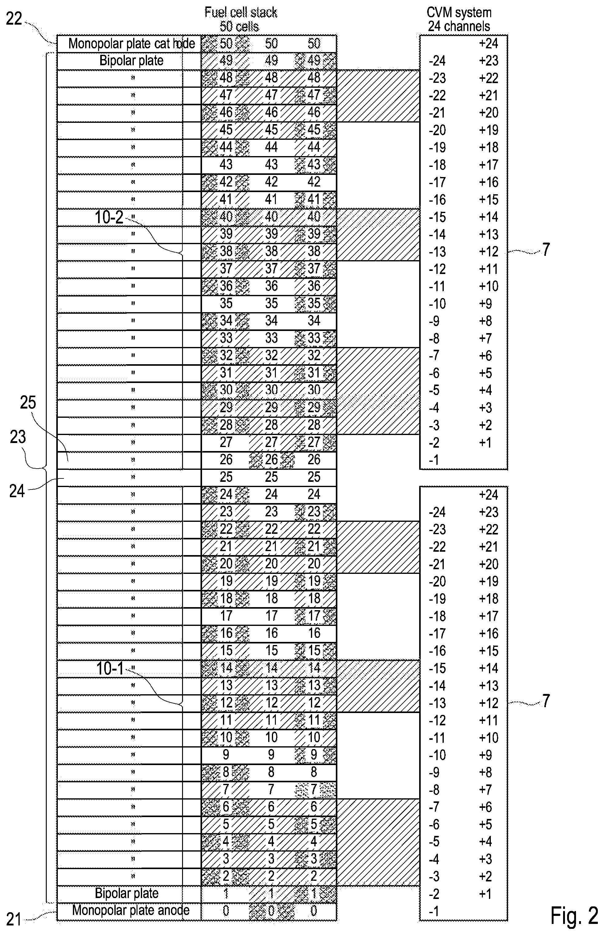
[0035] FIG. 2 : a second schematic view of a fuel cell stack with two electric connectors;
[0036] FIG. 3: a perspective view of a fuel cell stack with three electric connectors; and
[0037] FIGS. 4 to 7: four examples of an electric connector.
DETAILED DESCRIPTION
[0038] In the following same and similar functioning elements are indicated with the same reference numerals.
[0039] FIGS. 1 and 2 show two schematic views of a fuel cell stack 20 with two electric connectors 10 (10-1, 10-2). The fuel cell stack 20 comprises a plurality of bipolar plates 23, sandwiched between two monopolar plates 21 (anode) and 22 (cathode). The plates 21, 22, 23 are also referred to as fluid flow field plates.
[0040] For electrically contacting the plates 21, 22, 23 of the fuel cell stack 20, an electric connector 10 is provided. In the embodiments illustrated in FIGS. 1 and 2, each electric connector 10-1, 10-2 contacts 25 plates. However, any other number of plates may be possible.
[0041] Each electric connector 10-1, 10-2 comprises three units 11, 12, 13. Each unit 11, 12, 13 comprises a plurality of contact pins 1, 2, 3 which contact the plates 21, 22, 23. Each unit 11, 12, 13 is connected via conductive paths 4, 5, 6 to a plug 7.
[0042] A first pin 1 of each of the units 11, 12, 13 is adapted to provide a reference voltage. In FIG. 1, as the units 11, 12, 13 are arranged without skipping any plates, and the two electric connectors 10 are arranged without skipping any plates, the voltages of the fuel cell stack being monitored by the pins 1, 2 and 3 of the units 11, 12,13, except of the first pin 1 of the first unit 11 of the lower electric connector 10-1, can be monitored with respect to the reference voltage being provided by the first pin 1 of the first electric connector 10-1, i.e. with reference to the monopolar plate 21. As the first pin 1 of the upper electric connector 10-2 and the last pin 3 of the lower electric connector 10-1 are connected to the same plate 24, this connection functions as a kind of jumper.
[0043] This is facilitated as the first unit 11 of each electric connector 10 comprises a protrusion 14 on which the first pin 1 is arranged. The third unit 13 comprises a recess 15 being correspondingly formed opposed to the protrusion 14. The protrusion 14 and the recess 15 are corresponding. This is also shown in FIGS. 4 to 7.
[0044] This arrangement provides the advantage that the first pin 1 of the first unit 11 of the upper electric connector 10-2 may contact an anode of a plate 24 of the fuel cell stack 20 and that the last pin 3 of the third unit 13 of the lower electric connector 10-1 may contact a cathode of the same fluid flow field plate 24 of the fuel cell stack 20 as shown in FIG. 1. As explained above, the voltages of each plate 22, 23, 24 are measured with reference to the voltage of the monopolar plate 21 provided by the first pin 1 of the first unit 11 of the lower electric connector 10-1.
[0045] In FIG. 2, one plate 24 is skipped between the electric connectors 10. In this case, the voltages of the fuel cell stack being monitored by the pins 1, 2 and 3 of the units 11,12, 13 of the lower electric connector 10-1, except of the first pin 1 of the first unit 11 of the lower electric connector 10-1, can be monitored with respect to the reference voltage being provided by the first pin 1 of the first electric connector 10-1. i.e. with reference to tire monopolar plate 21. The voltages of the fuel cell stack being monitored by the pins 1, 2 and 3 of the units 11,12, 13 of the upper electric connector 10-2, except of the first pin 1 of the first unit 11 of the upper electric connector 10-2, can be monitored with respect to the reference voltage being provided by the first pin 1 of the first unit 11 of the upper electric connector 10-2, i.e. with reference to the plate 25. Thus, fluid flow field plates may be skipped between the electric connectors 10.
[0046] As can be seen in FIGS. 1 and 2, the contact pins 1, 2, 3 are arranged in three rows and are thus displaced or offset to each other. This provides the advantage that they may contact the plates 21, 22, 23 without contacting each other. Thus, short circuiting may be avoided. However, any other number of rows is possible.
[0047] Although each electric connector 10 is shown having three units 11, 12, 13, any other number of units may be used. Further, the electric connector 10 may each have a different number of units and/or a different number of contact pins.
[0048] In the embodiments as shown in FIGS. 1 and 2, the electric connectors 10 are each connected to a plug 7 which may be coupled to a cell voltage measurement system (not shown). It is also possible to connect each unit 11, 12, 13 with one separate plug 7. Also a combination of this arrangement of units and plugs is possible.
[0049] The contact pins 1, 2, 3 and the plugs 7 may be connected via conductive paths being bonded into a flexible plastic material. This is shown in more detail with reference to FIGS. 3 to 7.
[0050] FIG. 3 shows a perspective view of the fuel cell stack 20 of FIGS. 1 and 2.
[0051] As can be seen, the contact pins 1, 2, 3 of the electric connectors 10 are provided on a printed wire board. The plugs 7 may also be provided on a printed wire board and are connected to the contact pins 1, 2, 3 via conductive paths being bonded into a flexible plastic material, for example the same material as a protective layer of the printed wire board.
[0052] The plugs 7 are attached to a housing 26 of fuel cell stack 20. The housing 26 may be a touch protection of the fuel cell stack. In the embodiment shown in FIG. 3, the housing 26 comprises slots 27. In a preferred embodiment, the plugs 7 are mounted to the housing 26 by self-tapping screws 28 which engage with the slots 27. This provides a variable way of attaching the plugs 7 to the fuel cell stack 20 as no pre-fabricated holes are needed in the housing 26.
[0053] As the contact pins 1, 2, 3 of the electric connectors 10 are arranged on a rigid board, e.g. a printed wire board (PWB), an easy attachment of the electric connectors 10 to the fuel cell stack 20 is enabled. No additional holding elements are needed as they electric connectors 10 are hold in the fuel cell stack 20 by friction between the contact pins 1, 2, 3 and the plates 21, 22, 23, 24, 25.
[0054] Further, as the contact pins are provided on a printed wire board, the units 11, 12, 13 may be grouped variable which is shown in FIGS. 4 to 7. This provides an electric connector 10 being adjustable to several fuel cell stack requirements.
[0055] In particular the combination of the adjustable number of pins 1, 2, 3 and the variable attachment of the plugs 7 enables an improved adaption of the electric connectors 10 to fuel cell stack requirements. In particular, a fine tuning of the electric connectors 10 to the dimension, e.g. the number of plates, of the fuel cell stack 20 is provided.
[0056] The electric connector 10 of FIG. 4 comprises three units 11, 12, 13, each of which is connected to the plug 7 via conductive paths 4, 5, 6.
[0057] In the embodiment of FIGS. 4 to 7, each unit 11, 12, 13 comprises a protrusion 14 and a corresponding recess 15. Thus, the units 11, 12, 13 may be arranged adjacent to each other wherein the protrusion 14 of unit 12 engages into the recess 15 of unit 11 and the protrusion 14 of unit 13 engages into the recess 15 of unit 12.
[0058] If less contact pins are required, some of the contact pins, preferably one unit, may easily be cut away. This is done in FIG. 5, where the third unit 13 is cut away together with the corresponding conductive paths 6. Thus, the electric connector 10 only comprises two units 11, 12 with less contact pins than in FIG. 4.
[0059] As explained above, each unit 11, 12, 13 has its own reference voltage provided via the first pin 1. If the first pin 1 one of unit 11, 12, 13 is cut away due to an adjustment to a fuel cell stack requirement (for example a size of the fuel cell stack 20), another pin, which now represents the first pin, provides the reference voltage.
[0060] This may be repeated with the first unit 11 as shown in FIG. 6.
[0061] Due to the flexible conductive paths 4, 5, 6, the plugs 7 and the contact pins 1, 2, 3 may be arranged in an offset manner as shown in FIG. 7. Thus, the space being provided on the fuel cell stack 20 and the housing 26 may be optimally utilized.
[0062] The specific arrangement of the electric connector 10 as described above provides a variable and easy way of contacting plates within a fuel cell stack and an improved way of monitoring fuel cell stack voltages.
[0063] As the plurality of contact pins may be provided on a printed wire board, contacting of the plates may be done in a very variable manner. One or more contact pins of one unit may be cut away to enable a finer resolution of a possible total plate numbers. The overall assembly may thus be insensitive to fine tolerances. Further, the printed wire board may support heat expansion. In addition, it may be possible to switch the location of contact pins to facilitate unlimited variety of stack sizes.
REFERENCE SIGNS
[0064] 1 first pin [0065] 2 contact pin [0066] 3 last pin [0067] 4, 5, 6 conductive paths [0068] 7 plug [0069] 10 electric connector [0070] 11, 12, 13 unit [0071] 14 protrusion [0072] 15 recess [0073] 20 fuel cell stack [0074] 21, 22 monopolar plate [0075] 23 bipolar plate [0076] 24 plate [0077] 25 plate [0078] 26 housing [0079] 27 slots [0080] 28 screw
* * * * *
D00000
D00001
D00002
D00003
XML
uspto.report is an independent third-party trademark research tool that is not affiliated, endorsed, or sponsored by the United States Patent and Trademark Office (USPTO) or any other governmental organization. The information provided by uspto.report is based on publicly available data at the time of writing and is intended for informational purposes only.
While we strive to provide accurate and up-to-date information, we do not guarantee the accuracy, completeness, reliability, or suitability of the information displayed on this site. The use of this site is at your own risk. Any reliance you place on such information is therefore strictly at your own risk.
All official trademark data, including owner information, should be verified by visiting the official USPTO website at www.uspto.gov. This site is not intended to replace professional legal advice and should not be used as a substitute for consulting with a legal professional who is knowledgeable about trademark law.