Apparatus And Methods For Computerized Object Identification
Meier; Philip ; et al.
U.S. patent application number 16/783688 was filed with the patent office on 2020-06-04 for apparatus and methods for computerized object identification. The applicant listed for this patent is GoPro, Inc.. Invention is credited to Dimitry Fisher, Steven Hypnarowski, Philip Meier, Chance Roth.
| Application Number | 20200175640 16/783688 |
| Document ID | / |
| Family ID | 61005546 |
| Filed Date | 2020-06-04 |


View All Diagrams
| United States Patent Application | 20200175640 |
| Kind Code | A1 |
| Meier; Philip ; et al. | June 4, 2020 |
APPARATUS AND METHODS FOR COMPUTERIZED OBJECT IDENTIFICATION
Abstract
Apparatus and methods for identification of a coded pattern visible to a computerized imaging apparatus while invisible or inconspicuous to human eyes. A pattern and/or marking may serve to indicate identity of an object, and/or the relative position of the pattern to a viewer. While some solutions exist for identifying patterns (for example, QR codes), they may be visually obtrusive to a human observer due to visual clutter. In exemplary implementations, apparatus and methods are capable of generating patterns with sufficient structure to be used for either discrimination or some aspect of localization, while incorporating spectral properties that are more aesthetically acceptable such as being: a) imperceptible or subtle to the human observer and/or b) aligned to an existing acceptable visual form, such as a logo. In one variant, a viewer comprises an imaging system comprised as a processor and laser scanner, or camera, or moving photodiode.
| Inventors: | Meier; Philip; (San Diego, CA) ; Fisher; Dimitry; (San Diego, CA) ; Roth; Chance; (San Diego, CA) ; Hypnarowski; Steven; (Valley Center, CA) | ||||||||||
| Applicant: |
|
||||||||||
|---|---|---|---|---|---|---|---|---|---|---|---|
| Family ID: | 61005546 | ||||||||||
| Appl. No.: | 16/783688 | ||||||||||
| Filed: | February 6, 2020 |
Related U.S. Patent Documents
| Application Number | Filing Date | Patent Number | ||
|---|---|---|---|---|
| 15858637 | Dec 29, 2017 | 10580102 | ||
| 16783688 | ||||
| 14923204 | Oct 26, 2015 | 9881349 | ||
| 15858637 | ||||
| 62068166 | Oct 24, 2014 | |||
| Current U.S. Class: | 1/1 |
| Current CPC Class: | G06T 1/0014 20130101; G06K 9/4671 20130101 |
| International Class: | G06T 1/00 20060101 G06T001/00; G06K 9/46 20060101 G06K009/46 |
Claims
1. A non-transitory computer-readable storage medium, comprising processor-executable instructions for controlling, in response the instructions, an autonomous vehicle to traverse a portion of an operational environment of the autonomous vehicle based on object tracking by: obtaining a first image of a video captured by an imaging device of the autonomous vehicle; processing the first image to obtain first object tracking data identifying a portion of the first image based on a characteristic of a color of the portion of the first image, wherein the portion of the first image corresponds to an object captured by the first image, and wherein the first image includes at least one other portion; autonomously controlling an orientation of the autonomous vehicle based on the first object tracking data; obtaining a second image, the second image subsequent to the first image in the video; processing the second image to obtain second object tracking data identifying a portion of the second image based on the characteristic of the color of the portion of the second image, wherein the portion of the second image corresponds to the object captured by the second image, and wherein the second image includes at least one other portion; and autonomously controlling the orientation of the autonomous vehicle based on the second object tracking data.
2. The non-transitory computer-readable storage medium of claim 1, wherein processing the first image includes processing the image based on pixel intensity for at least two pixels of the first image.
3. The non-transitory computer-readable storage medium of claim 1, wherein processing the first image includes: obtaining data identifying a region within the first image; and obtaining the first object tracking data based on the region.
4. The non-transitory computer-readable storage medium of claim 1, wherein: the characteristic includes a first shape formed by the object in the first image; autonomously controlling the orientation of the autonomous vehicle based on the first object tracking data includes autonomously controlling the orientation of the autonomous vehicle in response to identifying the first shape; the characteristic includes a second shape formed by the object in the second image; and autonomously controlling the orientation of the autonomous vehicle based on the second object tracking data includes autonomously controlling the orientation of the autonomous vehicle in response to identifying the second shape.
5. The non-transitory computer-readable storage medium of claim 4, wherein: autonomously controlling the orientation of the autonomous vehicle based on the first object tracking data includes autonomously controlling a distance of the autonomous vehicle from the object; and autonomously controlling the orientation of the autonomous vehicle based on the second object tracking data includes autonomously controlling the autonomous vehicle independent of the object.
6. A method of autonomous vehicle control based on object tracking, the method comprising: obtaining an image; processing the image to obtain object tracking data identifying a portion of the image based on a characteristic of a color of the portion of the image, wherein the portion of the image corresponds to an object captured by the image, and wherein the image includes at least one other portion; and autonomously controlling an orientation of the autonomous vehicle relative to the object based on the object tracking data.
7. The method of claim 6, wherein: obtaining the image includes obtaining the image by an image processor from an imaging device of the autonomous vehicle via a computing communication link.
8. The method of claim 6, wherein processing the image includes processing the image based on pixel intensity for at least two pixels of the image.
9. The method of claim 6, wherein autonomously controlling the orientation of the autonomous vehicle includes autonomously controlling a distance of the autonomous vehicle from the object.
10. The method of claim 6, wherein processing the image includes: obtaining data identifying a region within the image; and obtaining the object tracking data based on the region.
11. The method of claim 10, wherein the region is rectangular.
12. The method of claim 6, wherein the characteristic includes a shape formed by the object.
13. The method of claim 12, wherein autonomously controlling the orientation of the autonomous vehicle includes autonomously controlling the orientation of the autonomous vehicle in response to identifying the shape.
14. The method of claim 6, wherein: the image is a first image of a video captured by the imaging device, the method further comprising: obtaining a second image, the second image subsequent to the first image in the video; processing the second image to obtain second object tracking data identifying a portion of the second image based on the characteristic of the color of the portion of the second image, wherein the portion of the second image corresponds to the object captured by the second image, and wherein the second image includes at least one other portion; and autonomously controlling the orientation of the autonomous vehicle relative to the object based on the second object tracking data.
15. A system comprising: an image processor, the image processor including a first communication device; and an autonomous vehicle, the autonomous vehicle including: a second communication device; and an image capture device; wherein: the image capture device is configured to obtain an image; the first communication device is configured to communicate the image to the second communication device via a computing communication link; the image processor is configured to process the image to obtain object tracking data identifying a portion of the image based on a characteristic of a color of the portion of the image, wherein the portion of the image corresponds to an object captured by the image, and wherein the image includes at least one other portion; and the autonomous vehicle is configured to control an orientation of the autonomous vehicle relative to the object based on the object tracking data.
16. The system of claim 15, wherein the image processor is configured to process the image based on pixel intensity for at least two pixels of the image.
17. The system of claim 15, wherein the autonomous vehicle is configured to control the orientation of the autonomous vehicle by autonomously controlling a distance of the autonomous vehicle from the object.
18. The system of claim 15, wherein the image processor is configured to process the image by: obtaining data identifying a region within the image; and obtaining the object tracking data based on the region.
19. The system of claim 15, wherein: the image is a first image of a video captured by the image capture device; the image capture device is configured to obtain a second image, the second image subsequent to the first image in the video; the image processor is configured to process the second image to obtain second object tracking data identifying a portion of the second image based on the characteristic of the color of the portion of the second image, wherein the portion of the second image corresponds to the object captured by the second image, and wherein the second image includes at least one other portion; and the autonomous vehicle is configured to control the orientation of the autonomous vehicle relative to the object based on the second object tracking data.
20. The system of claim 15, wherein: the characteristic includes a shape formed by the object; and the autonomous vehicle is configured to control the orientation of the autonomous vehicle by autonomously controlling the orientation of the autonomous vehicle in response to identifying the shape.
Description
CROSS-REFERENCE TO RELATED APPLICATIONS
[0001] This application is a continuation of U.S. Utility patent application Ser. No. 15/858,637, filed on Dec. 29, 2017, which is a continuation of U.S. Utility patent application Ser. No. 14/923,204, filed on Oct. 26, 2015, which claims priority to and the benefit of U.S. Provisional Patent Application Ser. No. 62/068,166, filed on Oct. 24, 2014, the disclosures of which are incorporated herein by reference in their entireties.
COPYRIGHT
[0002] A portion of the disclosure of this patent document contains material that is subject to copyright protection. The copyright owner has no objection to the facsimile reproduction by anyone of the patent document or the patent disclosure, as it appears in the Patent and Trademark Office patent files or records, but otherwise reserves all copyright rights whatsoever.
TECHNICAL FIELD
[0003] The present disclosure relates to computer vision and identification of objects by robotic devices.
BACKGROUND
[0004] Object detection and/or identification may be utilized in a variety of applications such as navigation, surveillance, retail, agriculture, public event infrastructure, and or other applications. While some solutions may exist for the identity of patterns (e.g., QR code) they may be often visually glaring and/or offensive to people because they add visual clutter to a scene, and/or reveal objects being marked thereby potentially exposing presence of a security and/or its operational characteristics. Here we propose methods and apparatus may provide for less visible means for marking and/or identifying objects by robotic devices.
SUMMARY
[0005] A method of detecting an object by a computerized imaging apparatus is disclosed. In one embodiment, the method comprise: observing an object, wherein the object comprises a pattern; sensing at least a portion of the pattern on the object; and identifying the object based on the sensed at least portion of the pattern; wherein the pattern comprises at least one medium that is undetectable via wavelengths that are visible to a human eye but detectable by the computerized imaging apparatus.
[0006] In one variant, sensing the pattern comprises sensing a first medium that is absorbent at a given wavelength range outside a given human-visible spectral range, and a second medium that is less absorbent in the given spectral range relative to the first medium. In a second variant, the first medium and the second medium comprise fiber threads woven into a textile of the object. In a third variant, the first medium and the second medium comprise material that was printed onto the object by a 3-D printing process.
[0007] In some cases, sensing the pattern comprises sensing a spectrum of metameric coloration.
[0008] In other cases, sensing the pattern comprises sensing a polarized composition of reflected light. For example, in one such case, responsive to an electro-optical device changing a composition of the polarized composition of reflected light, identifying the changed composition of the polarized reflected light.
[0009] In still other embodiments, sensing the pattern on the object comprises sensing a given wavelength range that comprises an infrared or an ultraviolet portion.
[0010] An article of manufacture is disclosed. In one embodiment, the article of manufacture includes: a first thread type characterized by a first optical property and a second thread type characterized by a second optical property, the threads of the first type and the second type combined into a pattern on a textile fabric forming at least a portion of the article of manufacture. In one such exemplary embodiment, the first optical property and the second optical property are indistinguishable by a human eye; and the first optical property and the second optical property are selected to be distinguishable by an imaging sensor.
[0011] In one variant, the first optical property is distinguishable from the second optical property by the imaging sensor based on one or more of light reflectance, wavelength, or polarization.
[0012] In a second variant, the pattern comprises one or more geometric shapes.
[0013] In a third variant, the pattern further comprises a portion that is visible to the human eye.
[0014] A method of tracking a person by a robotic apparatus is disclosed. In one embodiment, the method includes: acquiring a representation of the person at a distance; identifying a characteristic of a pattern disposed on the representation of the person; and adjusting a trajectory of the apparatus so as to maintain a range to the person within a target range. In one exemplary embodiment, the method further includes: detecting a signal at a wavelength invisible to a human; and the pattern comprises one or more elements that are configured to reflect the signal at the wavelength.
[0015] In one variant, the signal comprises light reflected from a garment of the human.
[0016] In a second variant, the signal comprises light generated from a special illuminant.
[0017] In a third variant, the method includes identifying the characteristic comprises identifying one or more geometric shapes of the pattern.
[0018] A system configured to detect an object is disclosed. In one embodiment, the system includes: a data structure that associates at least the object with a marking in a first spectral range that is unobservable by a human eye; a computerized imaging apparatus comprising a detector configured to receive one or more spectral components, the detector comprising a filter configured to block or reduce a second spectral range that is in a visible portion of the spectrum, the second spectral range being in one or more polarizations; and responsive to receiving a spectral component in the first spectral range, the computer imaging apparatus is configured to identify the object.
[0019] In one variant, the computerized imaging apparatus further comprises an illuminant configured to generate light that comprises at least the first spectral range.
[0020] In a second variant, the computerized imaging apparatus further comprises a fixture configured to mark the object with the marking.
[0021] In a third variant, the computerized imaging apparatus is further configured to detect changes in the marking.
[0022] These and other objects, features, and characteristics of the present invention, as well as the methods of operation and functions of the related elements of structure and the combination of parts and economies of manufacture, will become more apparent upon consideration of the following description and the appended claims with reference to the accompanying drawings, all of which form a part of this specification, wherein like reference numerals designate corresponding parts in the various figures. It is to be expressly understood, however, that the drawings are for the purpose of illustration and description only and are not intended as a definition of the limits of the invention. As used in the specification and in the claims, the singular form of "a", "an", and "the" include plural referents unless the context clearly dictates otherwise.
BRIEF DESCRIPTION OF THE DRAWINGS
[0023] FIG. 1A is a graphical illustration depicting viewing of a pattern on a surface by a human eye, according to one or more implementations.
[0024] FIG. 1B is a graphical illustration depicting viewing of a pattern on a surface by an imaging apparatus, according to one or more implementations.
[0025] FIG. 2 is a block diagram illustrating an imaging sensor comprising a lens and a selective filter directed at an object surface that contains a code, according to one or more implementations.
[0026] FIG. 3 is a graphical illustration depicting an imaging sensor with a lens and filter that is directed at an article of clothing with a code embedded into the fabric, in accordance with one or more implementations.
[0027] FIG. 4A is a graphical illustration depicting an exemplary item of clothing comprising a pattern of rectangles that is visually unobtrusive while machine detectable, in accordance with one or more implementations.
[0028] FIG. 4B is a graphical illustration depicting an exemplary item of clothing comprising a pattern of fractals that is visually unobtrusive while machine detectable, in accordance with one or more implementations.
[0029] FIG. 4C is a graphical illustration depicting an exemplary item of clothing comprising a pattern of circles that is visually unobtrusive while machine detectable, in accordance with one or more implementations.
[0030] FIG. 5 is a plot depicting distance distribution of pattern elements of, e.g., patterns of FIG. 4A, in accordance with one or more implementations.
[0031] FIG. 6A is a functional block diagram illustrating components of a computerized apparatus configured for use with one or more implementations disclosed herein.
[0032] FIG. 6B is a functional block diagram illustrating components of a computerized imaging system configured to detect human non-detectable codes, in accordance with one or more implementations.
[0033] FIG. 7 is a graphical illustration depicting determination of vehicle relative position by an imaging sensor capable of detecting machine detectable code on a surface of vehicle, according to one or more implementations.
[0034] FIG. 8 is a graphical illustration depicting a downward facing imaging apparatus configured to facilitate vehicle navigation, according to one or more implementations.
[0035] FIG. 9A is a graphical illustration depicting an imaging apparatus disposed on a cart and configured to enable cart navigation by tracking an invisible code disposed on a person, in accordance with one or more implementations.
[0036] FIG. 9B is a graphical illustration depicting a system including a ceiling-mounted imaging apparatus configured to image an indoor environment and detecting a code on a person and/or objects, in accordance with one or more implementations.
[0037] FIG. 10A is a graphical illustration depicting application of an identification material onto a plant for detection by a computerized imaging apparatus, in accordance with one or more implementations.
[0038] FIG. 10B is a graphical illustration depicting appearance to a human observer of an unmarked plant and a plant marked with an invisible code applied thereon, in accordance with one or more implementations.
[0039] FIG. 10C is an image illustrating detection by a computerized imaging apparatus of a plant marked with an invisible code, in accordance with one or more implementations.
[0040] FIG. 11 is a logical flow diagram illustrating a method of using invisible coding for triggering an action based on identification of the code, in accordance with one or more implementations.
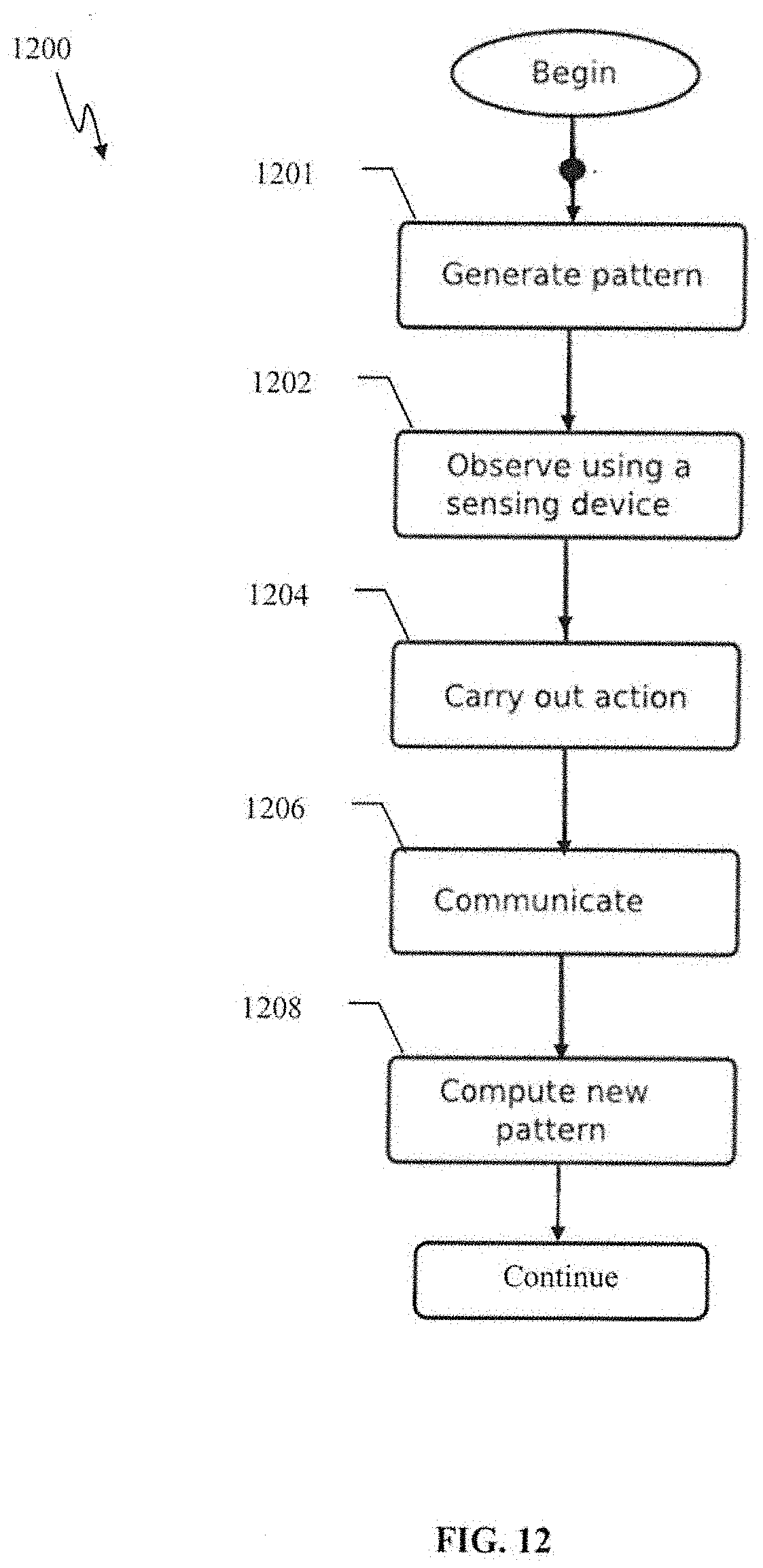
[0041] FIG. 12 is a logical flow diagram illustrating a method of pattern adjustment for use with the computer detectable pattern methodology, in accordance with one or more implementations.
[0042] FIG. 13 is a logical flow diagram illustrating a method of detecting a pattern in an image for use with the computer detectable pattern methodology, in accordance with one or more implementations.
[0043] FIG. 14A is a graphical illustration depicting application of an expression agent to a living plant to enable subsequent identification by a computerized imaging apparatus, in accordance with one or more implementations.
[0044] FIG. 14B is a graphical illustration depicting absorption of the agent by the plant and expression of a characteristic by the plant, in accordance with one or more implementations.
[0045] FIG. 14C is a graphical illustration depicting appearance to a human observer of an unmarked plant and a plant with expressed characteristic, in accordance with one or more implementations.
[0046] FIG. 14D is graphical illustration depicting detection by a computerized imaging apparatus of the expressed characteristic of the plant, in accordance with one or more implementations.
[0047] FIG. 15 is block diagram depicting detection of a pattern in an image for use with various implementations of computer detectable pattern methodology, in accordance with one or more implementations.
[0048] All Figures disclosed herein are .COPYRGT. Copyright 2015 Brain Corporation. All rights reserved.
DETAILED DESCRIPTION
[0049] Implementations of the present technology will now be described in detail with reference to the drawings, which are provided as illustrative examples so as to enable those skilled in the art to practice the technology. Notably, the figures and examples below are not meant to limit the scope of the present disclosure to a single implementation or implementation, but other implementations and implementations are possible by way of interchange of or combination with some or all of the described or illustrated elements. Wherever convenient, the same reference numbers will be used throughout the drawings to refer to same or like parts.
[0050] Where certain elements of these implementations can be partially or fully implemented using known components, only those portions of such known components that are necessary for an understanding of the present invention will be described, and detailed descriptions of other portions of such known components will be omitted so as not to obscure the disclosure.
[0051] In the present specification, an implementation showing a singular component should not be considered limiting; rather, the invention is intended to encompass other implementations including a plurality of the same component, and vice-versa, unless explicitly stated otherwise herein.
[0052] Further, the present disclosure encompasses present and future known equivalents to the components referred to herein by way of illustration.
[0053] As used herein, the term "bus" is meant generally to denote all types of interconnection or communication architecture that is used to access the synaptic and neuron memory. The "bus" may be optical, wireless, infrared, and/or another type of communication medium. The exact topology of the bus could be for example standard "bus", hierarchical bus, network-on-chip, address-event-representation (AER) connection, and/or other type of communication topology used for accessing, e.g., different memories in pulse-based system.
[0054] As used herein, the term "camera" refers without limitation or estoppel to any imaging device or sensor configured to capture, record, and/or convey still and/or video imagery, which may be sensitive to visible parts of the electromagnetic spectrum and/or invisible parts of the electromagnetic spectrum (e.g., infrared, ultraviolet, and/or other wavelengths that are not perceptible to humans).
[0055] As used herein, the terms "computer", "computing device", and "computerized device" may include one or more of personal computers (PCs) and/or minicomputers (e.g., desktop, laptop, and/or other PCs), mainframe computers, workstations, servers, personal digital assistants (PDAs), handheld computers, embedded computers, programmable logic devices, personal communicators, tablet computers, portable navigation aids, J2ME equipped devices, cellular telephones, smart phones, personal integrated communication and/or entertainment devices, and/or any other device capable of executing a set of instructions and processing an incoming data signal.
[0056] As used herein, the term "computer program" or "software" may include any sequence of human and/or machine cognizable steps which perform a function. Such program may be rendered in a programming language and/or environment including one or more of C/C++, C #, Fortran, COBOL, MATLAB.TM., PASCAL, Python, assembly language, markup languages (e.g., HTML, SGML, XML, VoXML), object-oriented environments (e.g., Common Object Request Broker Architecture (CORBA)), Java.TM. (e.g., J2ME, Java Beans), Binary Runtime Environment (e.g., BREW), and/or other programming languages and/or environments.
[0057] As used herein, the terms "connection", "link", "transmission channel", "delay line", "wireless" may include a causal link between any two or more entities (whether physical or logical/virtual), which may enable information exchange between the entities.
[0058] As used herein, the term "memory" may include an integrated circuit and/or other storage device adapted for storing digital data. By way of non-limiting example, memory may include one or more of ROM, PROM, EEPROM, DRAM, Mobile DRAM, SDRAM, DDR/2 SDRAM, EDO/FPMS, RLDRAM, SRAM, "flash" memory (e.g., NAND/NOR), memristor memory, PSRAM, and/or other types of memory.
[0059] As used herein, the terms "integrated circuit", "chip", and "IC" are meant to refer to an electronic circuit manufactured by the patterned diffusion of trace elements into the surface of a thin substrate of semiconductor material. By way of non-limiting example, integrated circuits may include field programmable gate arrays (e.g., FPGAs), a programmable logic device (PLD), reconfigurable computer fabrics (RCFs), application-specific integrated circuits (ASICs), and/or other types of integrated circuits.
[0060] As used herein, the terms "microprocessor" and "digital processor" are meant generally to include digital processing devices. By way of non-limiting example, digital processing devices may include one or more of digital signal processors (DSPs), reduced instruction set computers (RISC), general-purpose (CISC) processors, microprocessors, gate arrays (e.g., field programmable gate arrays (FPGAs)), PLDs, reconfigurable computer fabrics (RCFs), array processors, secure microprocessors, application-specific integrated circuits (ASICs), and/or other digital processing devices. Such digital processors may be contained on a single unitary IC die, or distributed across multiple components.
[0061] As used herein, the term "network interface" refers to any signal, data, and/or software interface with a component, network, and/or process. By way of non-limiting example, a network interface may include one or more of FireWire (e.g., FW400, FW800, etc.), USB (e.g., USB2), Ethernet (e.g., 10/100, 10/100/1000 (Gigabit Ethernet), 10-Gig-E, etc.), MoCA, Coaxsys (e.g., TVnet.TM.), radio frequency tuner (e.g., in-band or OOB, cable modem, etc.), Wi-Fi (802.11), WiMAX (802.16), PAN (e.g., 802.15), cellular (e.g., 3G, LTE/LTE-A/TD-LTE, GSM, etc.), IrDA families, and/or other network interfaces.
[0062] As used herein, the term "paint" refers without limitation or estoppel to one or more pigment(s), dye(s), colorant(s), film(s), layer(s), and/or any other medium, material, and/or element that alters absorption, transmission, refraction, and/or reflection of electromagnetic radiation when placed, sprayed, deposited, mixed, dissolved, added, applied, and/or otherwise disposed on or integrated with a material surface.
[0063] As used herein, the term "robot" refers without limitation or estoppel to an device, vehicle, computer, AI agent, surveillance system or device, control system or device, and/or other computerized device capable of autonomous, semi-autonomous, or controlled operation.
[0064] As used herein, the term "Wi-Fi" includes one or more of IEEE-Std. 802.11, variants of IEEE-Std. 802.11, standards related to IEEE-Std. 802.11 (e.g., 802.11 a/b/g/n/s/v), and/or other wireless standards.
[0065] As used herein, the term "wireless" means any wireless signal, data, communication, and/or other wireless interface. By way of non-limiting example, a wireless interface may include one or more of Wi-Fi, Bluetooth, 3G (3GPP/3GPP2), HSDPA/HSUPA, TDMA, CDMA (e.g., IS-95A, WCDMA, etc.), FHSS, DSSS, GSM, PAN/802.15, WiMAX (802.16), 802.20, narrowband/FDMA, OFDM, PCS/DCS, LTE/LTE-A/TD-LTE, analog cellular, CDPD, satellite systems, millimeter wave or microwave systems, acoustic, infrared (i.e., IrDA), and/or other wireless interfaces.
[0066] A pattern and/or demarcation may be applied to indicate the identity of an object and/or surface, and/or their relative position of the pattern to a viewer. A viewer may be an imaging system comprising a processor in communication with one or more of a laser scanner, a camera, a moving photodiode, and/or other components. While some solutions may exist for identifying patterns (e.g., QR code) they may be often visually glaring and may be offensive to people because they add visual clutter to a scene. Exemplary implementations include methods capable of generating patterns with one or both of: (1) sufficient structure to be used for either discrimination, or some aspect of localization, and/or (2) spectral properties that are more aesthetically acceptable (e.g., imperceptible or subtle to the human observer and/or aligned to an existing acceptable visual form, such as a logo).
[0067] In some implementations, methods of generating spectral patterns that may not be detectable by humans (and/or appear subtle to humans) are disclosed.
[0068] In some implementations, active targets may be provided using electro-sensitive films or liquid crystal films to change any of the active target's aforementioned optic properties dynamically. In some variants, active targets can display different information according to their input signals (similar to the manner in which an LCD display operates). Certain implementations may be optimized for thinness, flexibility, and/or degree of perceptibility with the human eye).
[0069] One or more implementations disclosed herein may work in daylight or artificial light, and may not require a special illuminant. Some implementations may involve special-illuminant approaches such as fluorescence targets, x-ray absorption targets, and/or other approaches. In some implementations, targets may be configured for use with polarized light. By way of an illustration, quarter wave plates for a given visible wavelength may become apparent in polarized light.
[0070] In some variants, a quick response (QR) code may be utilized with the methodology described herein. In some implementations, the QR code may be configured based on a modification of light polarization that may be reflected from the surface of the code area. For example, a known pattern may be utilized (e.g., a checkerboard patch and/or one or more square bull's eyes) that are specifically designed to aid in QR code detection, alignment, and recognition of encoding standard.
[0071] In some implementations, various methods may be employed for pattern detection, e.g., optical tracking and alignment, blob tracking, de-warping, similarity maximization, and/or other methods. In one or more implementations of machine learning, one or more of unsupervised machine learning (clustering, greedy feature extraction, recurrent networks) and/or supervised machine learning (multilayer perceptron, working memory, nearest neighbor classifier) algorithms may be employed.
[0072] In one or more implementations, an ultraviolet (UV) absorbent paint may be used for identifying a target using a transmitted-light. The term target may be used to describe a QR code, a bull's-eye pattern, an item identification (ID), e.g., a serial number, a pennant number, and/or other characteristic.
[0073] A substance transparent to the visible light but absorbing near-UV light may form a good transmission target when a volume-applied, layer-applied, and/or surface-applied treatment of the substance is disposed on a transparent material such as glass, acrylic, polycarbonate, polyethylene, mica, and/or other transparent material.
[0074] In one or more implementations, an UV absorbent material may be used for identifying a target using reflected-light. A substance highly reflective to the visible light (e.g., white) but absorbing near-UV light may form a high contrast reflection target when applied. A transmitted-light target may be converted to a reflected-light target when a reflective layer is placed under it.
[0075] In some implementations, a combination of absorption and thin-film target approaches may be utilized. For example, a layer scattering visible light and absorbing UV may be over imposed on a layer that selectively reflects UV light at certain wavelengths.
[0076] In one or more implementations, a 3D printed object may be composed of two plastics that appear to be the same color, but have differing absorbance outside the visible spectrum (e.g., one absorbs UV light, and the other reflects it.) The deposition of the plastics into solid forms may be in accordance with a digitally defined policy that allows the surface marking to display a 2D pattern.
[0077] In one or more implementations, surface reflectance properties of an object may be used for embedding a code. For example, this may be done with a coating, by changing the material itself, by texturizing the material (e.g., glossy vs matte), and/or other approaches.
[0078] In some implementations, threads of fabric or composite (e.g., an in-weave in carbon fiber) may be dyed (e.g., UV absorptive) and/or coated (e.g., changing the diffraction of incident light) with a pigment, polymer, and/or paint. The combination of two or more different threads, or a treated thread upon an untreated background fabric, e.g., utilizing a Jacquard weaving technique or similar method, may allow for the creation of a 2D pattern prior to, during, and/or after the manufacturing of clothing, rugs, sheets, carpets, upholstery, and/or other fabrics. In one implementation, a series of circular dots are arranged on a hexagonal grid, such that the spacing between each dot is a fixed distance, allowing an external imaging system to more accurately assess the distance to the proximal surface of the object.
[0079] An imaging apparatus outfitted with an appropriately polarized filter may be used to detect the pattern. Other physical patterns may be used for augmented reality, unique identification, back projection, and/or other applications.
[0080] In one or more implementations, dichroic filters and/or thin-film optics may be utilized for target identification. By way of an illustration, a thin-layered target will reflect and transmit different wavelengths differently.
[0081] In some implementations, a pressurized spray container and/or other spraying device may deposit a substance (e.g., UV absorptive or UV reflective pigment) in a predetermined pattern (e.g., with the assistance of a stencil). The pigment may be invisible to the human eye, and thus may coat any surface to achieve the desired demarcation in the non-visual spectrum. In some implementations, two or more spray containers may be metameric and/or nearly metameric (i.e., both appear to be the same or similar to the human eye, e.g., RED 1 and RED 2). The containers may activate the same ratio of cone cells (S, M, and L) during transduction, but the albedo of natural light may differ, providing a signature between the two different reds, accessible by the right spectral filter. Such a filter may be designed or selected such that it discriminates between the two reds. Those skilled in the art will appreciate that the spectral absorption and reflection properties of the two sprayed substances (e.g., paints, pigments, dyes, and/or coatings) may be chosen so that they would look the same to the human eye under one light source but not under another (e.g., sunlight vs. tungsten light); and/or that the intensity of reflection from the two paints would inform a robot as to the ambient lighting conditions.
[0082] In some implementations, a water-insoluble marker (e.g., a chalk) and/or a water-soluble marker (e.g., a fertilizer) may be deposited on the ground. Fertilizer or other water-soluble substances may be taken up by the plants, selectively (by some plants) or non-selectively (by all plants in the treated area), altering their optical properties outside the human visible range and making them look different to a robot (e.g., for weeding or other agricultural purposes). A chalk, paint, spray, and/or other material may be used to mark plants, plant parts, and/or plant locations (e.g., mark the ground next to the plant) so that the difference between the marked and unmarked plants would be clearly visible to a robot, but invisible or inconspicuous to the human eye. In some implementations, special care may be taken to ensure that the materials used comply with organic and/or other specifications pertinent to the commercial and/or other plant growing procedures. In some implementations, special care may be taken to ensure that the materials used do not interfere in undesired manner with the vital processes of the plants and/or other organisms in the vicinity.
[0083] In some implementations, an organism (e.g., a plant, animal, and/or other organism) may be genetically and/or epigenetically modified to express and/or to suppress expression of novel, modified, and/or unmodified substance (e.g., pigment, opsin, and/or other substance) so that the entire organism and/or some parts thereof would appear different to a robot (e.g., outside the visible spectrum) yet similar or identical to a human eye, compared to an unmodified organism.
[0084] In some implementations, a silk screen, laser print, ink jet print, lithographic process, and/or other technique for applying material to surfaces may result in the generation of the desired patterned marking.
[0085] In some implementations, the electrical signal of a rasterized scan (e.g., for a CRT, LCD, LED. liquid crystal, eInk, mirasol, DLP, and/or other display technology), may result in the activation of pixels with spectral emissions that are the same in the visible range, but differ outside of the visible range.
[0086] Those skilled in the art will appreciate that the effects described above may be achieved not only by means of dyes or pigments that alter absorption and/or transmission and/or reflection of light, but also by (but not limited to) one or more of the following means: (1) thin-film, dichroic, interference, birefringent, and/or other linear or nonlinear optical components and/or coatings; (2) surfaces, coatings, and/or elements (e.g., quarter-wave plates) that may alter polarization of the transmitted and/or reflected light; (3) liquid-crystal devices; and/or (4) other means (e.g., electro- or chemo-sensitive) that may change their properties according to an external signal and/or ambient conditions, so that the invisible and/or inconspicuous pattern may change dynamically according to external input and/or ambient conditions.
[0087] Those skilled in the art will appreciate that additional information may be extracted from the optical properties of such markings outside the visible spectrum. For example, angle of view may be determined from the cutoff wavelength of a dichroic filter.
[0088] Various patterns may be utilized with the object tagging methodology described herein. Non-limiting examples of such patterns may include patterns of one or more of dots, stripes, squares, polygons, fractal patterns, barcodes and/or other algorithmically generated code and identification systems, combinations of patterns reflecting visible light and invisible electromagnetic waves, visible pattern and invisible metadata, invisible detection points, visible pattern identity, and/or other patterns.
[0089] In some implementations, pattern detection may include one or more of: (1) detection of a code (e.g., orange lump with some invisible spectral variation), (2) identification of features (e.g., location of circle centers in image plane), (3) processing of feature relationships (e.g., distances between particular points), (4) extraction of knowledge (identity of marker, depth, orientation or location), and/or other actions.
[0090] In some implementations, the following approaches may be employed for providing invisible and/or nearly imperceptible machine detectable patterns: (1) the use of polarized light; (2) the use of color metamers (e.g., colors which are substantially identical within the visible spectra of wavelength (human cone cells activate in substantially the same manner for a color and its metamers), but incorporate additional spectral components that are invisible or very subtle to humans); (3) the use of colors that are "close" in human perception, but very easy for a matching spectral notch filter to discriminate; (4) the use of different reflectance properties (e.g., glossy black vs matte black that is easy to detect with any reflected back projection, or infrared flash, but which may be subtle to the human eye); (5) the use of difference images for two different filtered cameras that can isolate the particular tags, and cancel out other patterns (e.g., useful in high signal to noise applications, based on the filter); and/or other approaches.
[0091] In some implementations, specific parameters of spectral energy emission may be used to provide the invisible codes.
[0092] In one or more implementations, the methodology described herein may be utilized for one or more of: (1) Tracking a marked object, (2) Identifying a marked object or class of marked objects, (3) Distinguishing between differently marked objects, (4) Keeping constant distance from a marked object, (5) Providing a teaching stimulus to a robot, (6) Providing object-related information to a robot, (7) Providing navigational information to a robot, (8) Providing a command to a robot (e.g., by changing, exposing, or obscuring the pattern), (9) Triggering an action or camera when a particular pattern or object is seen, (10) Triggering an action or camera when a particular pattern or object is seen in a particular range of parameters (e.g., distance, viewing angle, speed of motion, ambient conditions, and/or other parameters), and/or other applications.
[0093] FIG. 1A illustrates an example of a simple pattern 102 on a surface 110. The pattern 102 may comprise markings that may not be visible to a human eye 100. The pattern 102 may be an optically invisible marker (e.g., dyed), part of an aesthetic visual form on the surface 110, a pigment that is metameric with the surface, etc., as described supra.
[0094] Such a pattern may be distinguished by a non-human viewer. FIG. 1B illustrates detection of the pattern of FIG. 1A by an imaging sensor 150 characterized by a sensitivity enabling the sensor to detect the invisible markings (i.e., marking not visible to the human eye). The pattern 152 is observable by the sensor 150 and may be used as an input for further processing. Additionally shown is a fronto-parallel plane that may comprise a plane perpendicular to an axis that is normal to the plane of the pattern (e.g., the axis denoted by arrow 154 in FIG. 1B that may be perpendicular to the plane 160).
[0095] FIG. 2 illustrates another example of a distinguishable pattern detectable by a machine or apparatus 200, where an imaging sensor 202 comprising a lens 204 and a selective filter 206 directed at an object surface 220 that contains a code 222, according to one or more implementations. In one implementation, similar to the pattern shown in FIGS. 1A and 1B, the sensor 200 may be configured to detect the code 222 that otherwise may be invisible to humans. The code may be an adhesive, additive paint, and/or printed into the material of the object itself. Other structures, materials and/or mechanisms as described supra may be used exploit the different perceptive capabilities between a human observer and a machine sensor able to distinguish visual or spectral characteristics of the code 222.
[0096] FIG. 3 illustrates still another example of a machine observer 300, where an imaging sensor 302 comprising a lens 304 and filter 306 is directed at an article of clothing 310 with a code 312 embedded into the fabric, in accordance with one or more implementations. In one implementation, the code 312 comprises shapes recognizable by the machine 300 (e.g., triangles, rectangles, circles, etc.), and may comprise a sprayed pigmented dye, printed coating, or other substance with a particular absorptive or reflective property. Such a code may be recognizable by the machine observer under an appropriate light source (e.g., UV). Filter 306 may be a spectral filter that may or may not be necessary to for the sensor 302 to recognize the code 312, by virtue of spectral absorption and reflective properties of the filter 306 and/or the material of code 312, as described supra. Elsewhere on the fabric may be a logo or other visible feature 314, where the code 312 may be embedded thereon or implemented so as to be unnoticeable and visually unobtrusive to a human observer.
[0097] FIG. 4A is a graphical illustration depicting an item of clothing 430 comprising a pattern 432 that is visually unobtrusive while machine detectable, comprising a plurality of rectangles 446 disposed at a plurality of distances 448 from one another, in accordance with one or more implementations. In one implementation, a machine-detected view of the clothing 440 shows rectangles arranged among blank areas 442, 444. The pattern of rectangles 446, the presence of rectangles, and/or the distances 448 of rectangles may indicate an encoded pattern or signal for the machine detecting the pattern. Other shapes or polygons, e.g., circles (as in FIG. 4C) or triangles, in lieu of rectangles may be recognized by the machine. Such shapes may be formed individually or in a grouped manner, and by various means (e.g., coated, stenciled, dyed) as described supra, and may (to varying degrees and/or camouflaged with other visible features) or may not be perceptible to human observers. Certain spectral properties of material used to form the shapes (e.g., rectangles 446) may be taken advantage of in order to use various surfaces of the clothing 430. For example, shapes formed on both the front and the back may be detected using material that are relatively transparent. That is, material that absorbs and/or reflects non-visible light (e.g., infrared (IR), UV) may be detectable even though it is not in direct line of sight by a machine sensor.
[0098] FIG. 4B is a graphical illustration depicting an item of clothing 460 comprising a pattern that is visually unobtrusive while machine detectable, comprising a fractal pattern 402, in accordance with one or more implementations. In one implementation, a machine-detected view of the clothing 470 shows the fractal pattern visible to a machine sensor with distinct areas 472, 474 clearly distinguishable. The pattern to detect may comprise size, fractal level, location, presence, etc., of areas 472, 474. In another implementation, the detectable pattern may be the fractal properties of darkened areas (i.e., other than areas 472, 474). Such a pattern may be formed by various means (e.g., coated, stenciled, dyed) as described supra, and may or may not (to varying degrees and/or camouflaged with other visible features) be perceptible to human observers.
[0099] FIG. 4C is a graphical illustration depicting an item of clothing 480 comprising pattern that is visually unobtrusive while machine detectable, comprising circles 482 disposed at a plurality of distances 494 from one another, in accordance with one or more implementations. In one implementation, a machine-detected view of the clothing 490 shows a plurality of circles 492 arranged in a pattern. Distances 494 may vary or be constant for some or all of the circles 492. Such shapes and patterns may be formed individually or in a grouped manner, and by various means (e.g., coated, stenciled, dyed) as described supra, and may or may not (to varying degrees and/or camouflaged with other visible features) be perceptible to human observers.
[0100] FIG. 5 is a plot 500 depicting distance distribution of pattern elements of, e.g., patterns of FIG. 4B or 4C, in accordance with one or more implementations. For example, based on a horizontal or vertical sum of areas 472, 474 in FIG. 4B, a histogram 500 of distance (e.g., from one side of the pattern to the opposite side) plotted against area may be created. As another example, based on a horizontal or vertical sum of areas (or count) of circles 492 in FIG. 4C, a histogram 500 of distance (e.g., from one side of the pattern to the opposite side) plotted against area (or count) may be created. This data may be useful in identifying a visual pattern using a quantitative distribution pattern, determining characteristics of a pattern such as the distance of area-weighted or count-weighted average 502, or simplifying the machine-observed pattern by encoding into a plot. Quantitative data such as plot 500 or a tabular format thereof may be further analyzed or transmitted in a digital format that is more compact than the pattern itself, which may comprise images or degraded versions thereof. In some implementations, the distance may be measured as depth, particularly for patterns detectable from multiple surfaces (using, e.g., IR, UV) as described supra.
[0101] In some implementations, pattern identification may be configured based on polarization of light. Reflection of incident light at and/or close to the Brewster angle is strongly polarized even when the incident light (e.g., sunlight) is weakly polarized and/or not polarized at all. A surface of an object (e.g., 152 in FIG. 1B, 222 in FIG. 2, 312 in FIG. 3) may be coated with crystalline material predominantly oriented so that the reflection towards the detecting device (e.g., along a horizontal axis) would be polarized. In one or more implementations, an absorptive and/or a birefringent filter may be used to detect reflected light of a given polarization.
[0102] An imaging apparatus, (e.g., 150 in FIG. 1B, 202 in FIG. 2, 302 in FIG. 3) may employ a filter (e.g., 206 in FIG. 2, 306 in FIG. 3). The filter may modify intensity of the polarized portion of the light that may have been reflected from the pattern surface, relative the light portion that may have been reflected from areas outside the pattern surface. The imaging apparatus may comprise a processing component (e.g., 616 in FIG. 6A) configured to determine a difference between intensity (brightness) of pixels in a given image and/or to determine occurrence of a pattern. The pixel intensity variations within the image may be used to detect occurrence of one or more a predetermined patterns (QR code, barcode, pattern of bars or dots, Mandelbrot and/or other fractal set, and/or other patterns).
[0103] In some implementations, pattern identification may be configured based on a wavelength characteristic. By way of an illustration, a visually transparent while UV-absorbent spray (for instance such as used to protect works of art from UV radiation and/or Trek7 Ray Bloc UV Fabric Protector Spray) may be applied onto an object (e.g., a vehicle, a garment, and/or other) via a stencil. Sprayed portions of the pattern may be characterized by higher UV absorption (lower UV reflectance) than the unsprayed parts, and thus will look darker to the UV-sensitive imaging system.
[0104] An imaging apparatus, (e.g., 150 in FIG. 1B, 202 in FIG. 2, 302 in FIG. 3) may employ a filter (e.g., 206 in FIG. 2, 306 in FIG. 3) configured to absorb and/or reflect visible portion of the light spectrum while passing through near-UV radiation. In some implementations, the filter cutoff wavelength may be selected at wavelength between 300 nm and 400 nm (for example a photographic 403 filter). The imaging apparatus may comprise a detector component (e.g., a CMOS/Active pixel sensor) that may be sensitive to a near-UV radiation.
[0105] In some implementations, pattern identification may be configured based on a relative reflectance of the pattern components in the invisible part of the spectrum (in the above example--in the near UV).
[0106] In some implementations, pattern identification may be configured based on a comparison of outputs provided by two detectors. In some implementations, one detector equipped with a filter and the other without a filter. In some implementations, individual detector component may comprise respective while different filters. A difference image may be obtained by subtracting an image obtained by the first detector component from the image obtained by the second one detector.
[0107] FIG. 6A is a functional block diagram illustrating components of a computerized apparatus 600 configured for use with one or more implementations disclosed herein. The apparatus 600 may include one or more of a learning configuration unit 612, a memory 614, a processing unit 616, a user interface (UI) 618, a sensory unit 620, an electrical unit 622, a power unit 624, a communications unit 626, and/or other components. The learning configuration unit 612 may be configured to facilitated learning by apparatus 600. The memory 614 may be configured to store and/or provide access to information associated with apparatus 600. The processing unit 616 may provide processing capabilities to apparatus 600. The user interface (UI) 618 may be configured to receive information from a user and/or convey information to a user. The sensory unit 620 may be configured to sense an environment surrounding apparatus 600. The electrical unit 622 may be configured to facilitate locomotion of apparatus 600. The power unit 624 may be configured to provide electrical power to one or more components of apparatus 600. The communications unit 626 may be configured to facilitate communication of information to and from apparatus 600.
[0108] FIG. 6B is a functional block diagram illustrating components of a computerized imaging system 650 configured to detect human non-detectable codes via lens 658 of an imaging sensor 652, in accordance with one or more implementations. In one implementation, the imaging system of FIG. 6B may comprise an active display system (e.g., LCD) which may render a new code (e.g., on image 662) based on a sequence of predetermined images 660 (comprising images 662 through 664) and/or based on a communication protocol 676 that may include messages from a communication module 654 connected to the imaging sensor 652. In some implementations, the images are configured to be generated and transmitted to or from at least one CPU 670 (via link 668), which is configured to be in communication with a communication module 672. The CPU may insert or remove or otherwise modify the images 660.
[0109] As shown, information associated with the images or patterns 660 (e.g., 662 through 664) may be stored on a remote storage location 658 via path 674 and retrieved by the communication module 654 connected to the imaging sensor 652 via path 656. The direct receipt of information associated with the patterns or images may also be used (via path 672). For example, in some cases, direct information may be useful as control data for use in pattern identification or training to identify patterns based on a comparison of data provided by the communication modules 654, 672 and visually detected by the imaging sensor 652. Training of the imaging sensor 652 (or one or more components thereof, such as the learning configuration unit 612 of FIG. 6A) may be useful in improving, calibrating, or correcting detection sensitivity.
[0110] FIG. 7 is a graphical illustration depicting determination of a vehicle's 710 relative position by an imaging sensor 700 capable of detecting machine detectable code 722 on a surface 724 of vehicle 710, according to one or more implementations. The imaging sensor 700 of FIG. 7 may be configured to detect a code 722 on a surface of vehicle 724, and/or capable of extracting the relative position 706 of the imaging sensor with respect to the vehicle. The detected pattern 722 may be embedded in the license plate light or brake lights, and/or on the painted surface 724 of the vehicle. The pattern 722 may be chosen such that the estimate of an aspect of the relative position 706 is best measured (e.g., depth vs. translation), potentially optimized for different distances (e.g., detection at large distances, depth estimation at more proximal distances).
[0111] FIG. 8 is a graphical illustration depicting a downward facing imaging apparatus 800 configured to facilitate vehicle navigation, according to one or more implementations. In one implementation, the imaging apparatus 800 comprises a vehicle 802 having a lens 804 attached to an imaging sensor 806. The imaging apparatus 800 may be capable of navigating roads, terrain, or predetermined paths. A pattern of markings may be used to indicate navigational paths 816, 818, waypoints 810, 812, and/or potential actions. Waypoints 810, 812 may exist preceding and/or within intersections to facilitate anticipation and execution of turns. Waypoints 810, 812 may comprise markings on the ground or other locations (e.g., signs, billboards, buildings) that are visible only to the imaging sensor 806 to facilitate navigation and/or potential actions of the vehicle 802. Such markings may also be visible to human viewers and/or may be camouflaged within surrounding unobtrusive markings. Paths 818 may be curved so as to facilitate the navigation around obstacles 814. Paths on ground may be passively marked and/or actively controlled.
[0112] FIG. 9A is a graphical illustration depicting an imaging apparatus 900 disposed on a cart 910 and configured to enable cart navigation by tracking an invisible code 922 disposed on a person 920, in accordance with one or more implementations. The code 922 may comprise a pattern disposed on a belt and/or on the external surface of the clothing, detectable by an imaging sensor 906 associated with the cart 910. In some implementations, the code pattern 922 may be part of a design on belt and/or the external surface of the clothing worn by the person 920, such that the code pattern 922 is aesthetically unobtrusive to human viewers but machine detectable, such as with the imaging apparatus 900.
[0113] FIG. 9B is a graphical illustration depicting a system including a ceiling-mounted imaging apparatus 930 configured to image an indoor environment and detecting a code 942 on a person and/or objects, in accordance with one or more implementations. The system of FIG. 9B may be configured to image a person in an indoor environment detecting any codes on the person, or any objects on their person, or localized the person by virtue of interrupting the path from an known code behind the person or below their feet 944, 946. The location of the person may be sensed and interrelated between multiple cameras 932, 934, based on the presence of shared codes 942, 944 and/or 946 present in both cameras at the same time. These codes may be fixed in the environment or present on the person or vehicle passing through a scene.
[0114] FIG. 10A is a graphical illustration depicting application of an identification material 1006 onto a plant 1004 for detection by a computerized imaging apparatus, in accordance with one or more implementations.
[0115] In one or more implementations, the identification substance 1006 may comprise a spray configured to coat surface of the plant. The identification material may be detectable in an invisible part of electromagnetic spectrum (e.g., IR, UV). In one or more implementations, the substance may be taken up (via, e.g., absorption) by the plant. The substance uptake by the plant may modify absorption light spectra of the plant and/or portions thereof (e.g., leaves). The absorption spectra modification may be configured to be selective for some plants but not others, outside the human spectral visual range. Modification of one plant (e.g., 1004) but not others (e.g., plant 1002) will result in machine-identifiable difference inherent in the modified plant, as described infra.
[0116] In one or more implementations, the substance uptake may modify the genetic makeup and/or protein expression of the plant or fungus thereby affecting the absorption spectra of the plant.
[0117] FIG. 10B is a graphical illustration depicting appearance to a human observer of an unmarked plant 1002 and a plant 1024 to be marked with an invisible substance applied thereon. In visible portions of electromagnetic spectrum, both the marked and the unmarked plants may appear indistinguishable (based on properties of reflected light) from one another to the human observer.
[0118] FIG. 10C is an image illustrating detection of a plant 1024 marked with an invisible identification substance 1006 as viewed by a computerized imaging apparatus. In some implementations, the identification substance may be detected in IR or UV portions of the spectrum. Plants 1002, 1024 that were previously indistinguishable by human observer are shown to be distinguishable by a machine observer.
[0119] FIG. 11 is a logical flow diagram illustrating a method 1100 of using invisible coding for triggering an action based on identification of the code, in accordance with one or more implementations. At operation 1102, a special pattern may be applied (by one or more of the approaches described herein) to an object. The pattern may be inconspicuous or invisible to a human eye, but may be sensed ("seen") by a robot camera or other special sensing device. At operation 1104, the robot may sense the pattern using invisible parts of the electromagnetic spectrum, light polarization, color metamerism, and/or other approaches described herein. The pattern may include a marker (e.g., special symbol or symbols, arrangement, data, absorption pattern, QR code, and/or other markers) that is read or identified at operation 1106 by the robot camera or the special sensing device, and at operation 1108, causes the robot to carry out an appropriate action and/or provides the robot with pertinent information. The process may be repeated as necessary. For example, the apparent distance between pattern elements may provide the robot with data about the distance and angle to the pattern as the robot approaches and/or manipulates the object.
[0120] FIG. 12 is a logical flow diagram illustrating a method 1200 of pattern adjustment for use with the computer detectable pattern methodology, in accordance with one or more implementations. At operation 1201, a pattern may be generated dynamically (e.g., by means of a CRT, LCD, and/or other means) on an object. The pattern may be inconspicuous or invisible to a human eye, but may be sensed ("seen") by a robot camera or other special sensing device. For example, at operation 1202, the pattern may be sensed using invisible parts of the electromagnetic spectrum, light polarization, color metamerism, and/or other approaches described herein. The pattern may contain a marker (e.g., special symbol or symbols, arrangement, data, absorption pattern, QR code, and/or other marker) that is read or identified by the robot camera or the special sensing device, and causes the robot at operation 1204 to carry out an appropriate action and/or provides the robot with pertinent information. At operation 1206, the robot may then establish a unidirectional or bidirectional communication link with the object (e.g., using the same inconspicuous-pattern method, and/or a conventional link such as WiFi and/or other communications techniques) and inform the object that the pattern has been successfully read. The process may be repeated as necessary. For example, at operation 1208, the object may update the pattern and/or compute a new pattern (e.g., represent the next information packet) in response to being informed that the present pattern has been successfully read by the robot.
[0121] FIG. 13 illustrates a method 1300 of detecting a pattern in an image for use with the computer detectable pattern methodology in accordance with one or more implementations.
[0122] At operation 1302 of method 1300, a region, may be detected in an image, e.g., the region 1510 in the image 1500 of FIG. 15. In one or more implementations, the region may comprise a visible pattern, e.g., a company logo on a garment, a patch of color (e.g., background), and/or outline of a car (e.g., rear-view of a car trunk 724 comprising the pattern 722 in FIG. 7).
[0123] At operation 1304, one or more reference locations may be identified. In some implementations (e.g., such as illustrated in FIG. 15), the reference locations may comprise three non-collinear points (e.g., the points A, B, E 1522, 1524, 1526 in FIG. 15) also referred to as the key points comprising a portion of the pattern (e.g., 1520) being identified. In one or more implementation, the reference locations may comprise locations with a known configuration (e.g., corner locations of the area 314 in FIG. 3). A pattern coordinate frame may be determined based on the reference locations selected at operation 1304.
[0124] At operation 1306 pixel intensity may be evaluated within the region. In some implementations, the intensity evaluation may comprise determination of an intensity level (threshold) that may be used to distinguish the code portion (e.g., hashed polygon 1520 in FIG. 15 from the background portion (e.g., white background within the rectangle 1510 in FIG. 15). The code portion may correspond to an intensity level (tone) that may be detected by the computerized imaging apparatus (e.g., the apparatus 200 in FIG. 2 and/or 652 in FIG. 6). In some implementations, the code portion may comprise the invisible markings, filling potentially homogenous bounded forms, on a machine distinguishable background, e.g., the portion 1520 on the background 1510 in FIG. 15.
[0125] At operation 1308 pattern characteristic may be determined. In some implementations, the pattern characteristic may comprise one or more contrast inversion boundary (e.g., segment GH 1524 in FIG. 15), one or more corner points (e.g., the point denoted with capital letters A, B, C, D, E, F, G, H, J in FIG. 15), aspect ratio, and/or other parameters.
[0126] At operation 1310 the pattern characteristic may be transformed (registered) to a reference coordinate frame. In some implementations, the reference frame may be selected as, fronto-parallel with respect to the plane of the pattern. By way of an illustration, a fronto-parallel plane may comprise a plane perpendicular to an the axis normal to the plane of the pattern (e.g., the axis denoted by arrow 154 in FIG. 1B that may be perpendicular to the plane 160). The coordinate plane transformation may be configured based on a known configuration (e.g., distances in x-y), between the reference locations (e.g., 1522, 1524, 1526 in FIG. 15) with respect to one another in the pattern plane and the configuration for these locations determined from the image (e.g., at operation 1304). In one or more implementations, the transformation may comprise a translation and/or rotation in 2D or 3D space of one or more of the contrast inversion boundaries and/or one or more corner points.
[0127] At operation 1312, a similarity measure may be determined. In one or more implementations, the similarity map may comprise a comparison of the transformed pattern parameters to a template, a hash (e.g., perimeter, area, median distance, e.g., 502 in FIG. 5, distance variance), and/or other operations configured to enable a computationally efficient determination as to whether an observed pattern corresponds to a known pattern (code).
[0128] FIG. 14A is a graphical illustration depicting application of an expression agent 1406 to a living plant 1404 to enable subsequent identification by a computerized imaging apparatus in accordance with one or more implementations.
[0129] The expression agent 1406 may be applied via watering or other form of targeted application method to one or more select plants. In one or more implementations, the expression agent may comprise a substance that may be taken up (absorbed) by the plant via leaves and/or roots. The substance uptake by the plant may modify absorption light spectra of the plant and/or portions thereof (e.g., leaves), as illustrated by the plant 1414 in FIG. 14B. The absorption spectra modification outside the human spectral visual range may be configured for some selected plants (e.g., 1404) but not the other 1402.
[0130] In one or more implementations, the substance uptake may modify the genetic makeup and/or protein expression of the plant or fungus thereby affecting the absorption spectra of the plant (e.g., the plant 1414).
[0131] FIG. 14C illustrates appearance to a human observer of an unmarked plant 1422 and a plant 1424 marked with the expression agent. In visible portion of electromagnetic spectrum, both the marked 1424 and the unmarked plants 1422 may appear indistinguishable (based on properties of reflected light) from one another
[0132] FIG. 14D illustrates detection by a computerized imaging apparatus of a plant 1424 marked with the expression agent identification. Marked plant 1424 is clearly identifiable and distinguishable from unmarked plant 1422 from the viewpoint of the imaging apparatus, enabling the imaging apparatus or another entity (e.g., human viewer, other apparatus) to carry out an action based on the identification (e.g., operations 1108, 1204, 1208). In some implementations, the identification substance may be detected in IR or UV portions of the spectrum.
[0133] It will be recognized that while certain aspects of the disclosure are described in terms of a specific sequence of steps of a method, these descriptions are only illustrative of the broader methods of the invention, and may be modified as required by the particular application. Certain steps may be rendered unnecessary or optional under certain circumstances. Additionally, certain steps or functionality may be added to the disclosed implementations, or the order of performance of two or more steps permuted. All such variations are considered to be encompassed within the disclosure disclosed and claimed herein.
[0134] While the above detailed description has shown, described, and pointed out novel features of the disclosure as applied to various implementations, it will be understood that various omissions, substitutions, and changes in the form and details of the device or process illustrated may be made by those skilled in the art without departing from the disclosure. The foregoing description is of the best mode presently contemplated of carrying out the invention. This description is in no way meant to be limiting, but rather should be taken as illustrative of the general principles of the invention. The scope of the disclosure should be determined with reference to the claims.
* * * * *
D00000
D00001
D00002
D00003
D00004
D00005
D00006
D00007
D00008
D00009
D00010
D00011
D00012

D00013

XML
uspto.report is an independent third-party trademark research tool that is not affiliated, endorsed, or sponsored by the United States Patent and Trademark Office (USPTO) or any other governmental organization. The information provided by uspto.report is based on publicly available data at the time of writing and is intended for informational purposes only.
While we strive to provide accurate and up-to-date information, we do not guarantee the accuracy, completeness, reliability, or suitability of the information displayed on this site. The use of this site is at your own risk. Any reliance you place on such information is therefore strictly at your own risk.
All official trademark data, including owner information, should be verified by visiting the official USPTO website at www.uspto.gov. This site is not intended to replace professional legal advice and should not be used as a substitute for consulting with a legal professional who is knowledgeable about trademark law.