Lifting Arrangement For Wheel Loader
Plante; Sean ; et al.
U.S. patent application number 16/614092 was filed with the patent office on 2020-06-04 for lifting arrangement for wheel loader. The applicant listed for this patent is Guangxi LiuGong Machinery Co., Ltd.. Invention is credited to Sean Plante, Edward Wagner.
| Application Number | 20200173134 16/614092 |
| Document ID | / |
| Family ID | 62866543 |
| Filed Date | 2020-06-04 |


| United States Patent Application | 20200173134 |
| Kind Code | A1 |
| Plante; Sean ; et al. | June 4, 2020 |
Lifting Arrangement For Wheel Loader
Abstract
Provided is a lifting arrangement mountable to a frame arrangement of a vertical lift wheel loader. The lifting arrangement comprises a main arm support element, a main arm, and a guiding arrangement. The main arm support element comprises at least two longitudinal members interconnected by at least one connecting element.
| Inventors: | Plante; Sean; (Liuzhou, Guangxi, CN) ; Wagner; Edward; (Liuzhou, Guangxi, CN) | ||||||||||
| Applicant: |
|
||||||||||
|---|---|---|---|---|---|---|---|---|---|---|---|
| Family ID: | 62866543 | ||||||||||
| Appl. No.: | 16/614092 | ||||||||||
| Filed: | November 23, 2018 | ||||||||||
| PCT Filed: | November 23, 2018 | ||||||||||
| PCT NO: | PCT/CN2018/117219 | ||||||||||
| 371 Date: | November 15, 2019 |
| Current U.S. Class: | 1/1 |
| Current CPC Class: | E02F 3/38 20130101; E02F 3/283 20130101; E02F 3/422 20130101; E02F 3/42 20130101; E02F 3/3405 20130101; E02F 3/3408 20130101; E02F 3/342 20130101; E02F 9/0841 20130101; E02F 3/431 20130101 |
| International Class: | E02F 3/34 20060101 E02F003/34; E02F 3/42 20060101 E02F003/42 |
Foreign Application Data
| Date | Code | Application Number |
|---|---|---|
| Jan 26, 2018 | CN | 201810076343.4 |
Claims
1. A lifting arrangement mountable to a frame arrangement of a vertical lift wheel loader, the lifting arrangement comprising: a main arm support element; a main arm; and a guiding arrangement; wherein: the main arm support element comprises a frame arrangement side end portion and a main arm side end portion; the main arm support element is pivotably mountable at the frame arrangement side end portion to the frame arrangement of the vertical lift wheel loader such that the main arm side end portion of the main arm support element is movable in a direction which includes at least a component in a front-rear direction of the vertical lift wheel loader; the main arm is pivotably mounted at a mounting portion of the main arm to the main arm side end portion of the main arm support element and comprises an equipment connector at an equipment connector portion of the equipment connector located opposite to the mounting portion; the guiding arrangement is mountable to the frame arrangement of the vertical lift wheel loader for determining a movement of the main arm support element upon a pivot movement of the main arm such that upon pivoting the main arm between a lowered position and a lifted position, the equipment connector is guided along a predetermined path; and the main arm support element comprises at least two longitudinal members which are interconnected by at least one connecting element.
2. The lifting arrangement according to claim 1, wherein the main arm support element has a substantially H shape.
3. The lifting arrangement according to claim 1, wherein the main arm support element is formed as a welded structure.
4. The lifting arrangement according to claim 1, wherein the at least two longitudinal members and/or the at least one connecting element are formed in a box shape.
5. The lifting arrangement according to claim 1, wherein each of the at least two longitudinal members comprises a pair of side plates and a connecting plate, and wherein the pair of side plates are connected by the connecting plate such that each of the at least two longitudinal members have a substantially closed profile.
6. The lifting arrangement according to claim 1, wherein the at least two longitudinal members and the at least one connecting element form a rigid body for transferring forces from the main arm to the frame arrangement.
7. The lifting arrangement according to claim 1, wherein each of the at least two longitudinal members comprises: a frame arrangement side bearing portion in the frame arrangement side end portion for mounting the main arm support element to the frame arrangement; and a main arm side bearing portion in the main arm side end portion for mounting the main arm support element to the main arm.
8. The lifting arrangement according to claim 7, wherein the frame arrangement side bearing portions are axially spaced by a frame arrangement side distance and the main arm side bearing portions are axially spaced by a main arm side distance, the main arm side distance being greater than the frame arrangement side distance.
9. The lifting arrangement according to claim 8, wherein the main arm side distance is at least twice the frame arrangement side distance.
10. The lifting arrangement according to claim 1, wherein each of the longitudinal members is formed with a cranked configuration.
11. The lifting arrangement according to claim 1, wherein the connecting element is formed by a plurality of sheet metal elements, and wherein the plurality of sheet metal elements form a substantially closed space inside the plurality of sheet metal elements.
12. The lifting arrangement according to claim 1, wherein the main arm comprises a pair of arms and a connecting portion, and wherein the pair of arms are formed by substantially flat sheet metal members which are spaced from each other by the connecting portion connecting the pair of arms to each other.
13. The lifting arrangement according to claim 1, wherein the guiding arrangement comprises: at least one guiding link; at least one first guiding link mount; and at least one second guiding link mount; wherein: the at least one first guiding link mount is provided at an arm element; the at least one second guiding link mount is provided at the frame arrangement; and the at least one guiding link comprises a first guiding link mount end portion and a second guiding link mount end portion, the at least one guiding link being pivotably connected to the at least one first guiding link mount at the first guiding link mount end portion and to the second guiding link mount at the second guiding link mount end portion.
14. The lifting arrangement according to claim 1, wherein the main arm support element further comprises a center plate which is integrated in the connecting element and arranged between the longitudinal members.
15. The lifting arrangement according to claim 14, wherein the center plate comprises a mount for mounting a link mechanism for actuating an equipment mountable to the equipment connector.
16. The lifting arrangement according to claim 1, wherein the main arm support element is configured such that a torsional strength thereof is higher than a torsional strength of the main arm.
17. A frame arrangement comprising: a front frame portion comprising a mounting structure, wherein: a lifting arrangement is mounted to the front frame portion via the mounting structure; and the lifting arrangement comprises: a main arm support element; a main arm; and a guiding arrangement; wherein: the main arm support element comprises a frame arrangement side end portion and a main arm side end portion; the main arm support element is pivotably mountable at the frame arrangement side end portion to the frame arrangement such that the main arm side end portion of the main arm support element is movable in a direction which includes at least a component in a front-rear direction of the frame arrangement; the main arm is pivotably mounted at a mounting portion of the main arm to the main arm side end portion of the main arm support element and comprises an equipment connector at an equipment connector portion of the equipment connector located opposite to the mounting portion; the guiding arrangement is mountable to the frame arrangement for determining a movement of the main arm support element upon a pivot movement of the main arm such that upon pivoting the main arm between a lowered position and a lifted position, the equipment connector is guided along a predetermined path; and the main arm support element comprises at least two longitudinal members which are interconnected by at least one connecting element.
18. The frame arrangement according to claim 17, wherein each of the at least two longitudinal members comprises: a frame arrangement side bearing portion in the frame arrangement side end portion for mounting the main arm support element to the frame arrangement; and a main arm side bearing portion in the main arm side end portion for mounting the main arm support element to the main arm, wherein the main arm support element is mounted pivotably to the mounting structure via the frame arrangement side bearing portion.
19. The frame arrangement according to claim 17, wherein the guiding arrangement comprises: at least one guiding link; at least one first guiding link mount; and at least one second guiding link mount; wherein: the at least one first guiding link mount is provided at an arm element; the at least one second guiding link mount is provided at the frame arrangement; the at least one guiding link comprises a first guiding link mount end portion and a second guiding link mount end portion, the at least one guiding link being pivotably connected to the at least one first guiding link mount at the first guiding link mount end portion and to the second guiding link mount at the second guiding link mount end portion; and the second guiding link mount is connected to the front frame portion.
20. The frame arrangement according to claim 17, further comprising a main arm actuator connected at one end portion to the front frame portion and connected at another end portion to the main arm for lifting the main arm.
21. The frame arrangement according to claim 17, wherein the guiding arrangement is configured to guide movements of the main arm support element and movements of the main arm such that the equipment connector follows the predetermined path at least in sections of the movement upon moving the main arm between a lowered position and a lifted position and between the lifted position and the lowered position, and wherein the predetermined path is a vertical path.
22. The frame arrangement according to claim 17, wherein the front frame portion comprises a pair of front wheels.
23. A vertical lift wheel loader comprising: an equipment; a rear frame portion; and an articulating mechanism; wherein: the equipment is mounted to a frame arrangement via an equipment connector of a main arm of a lifting arrangement of the frame arrangement; the rear frame portion comprises a pair of rear wheels; and the frame arrangement and the rear frame portion are connected via the articulating mechanism to each other such that the frame arrangement and the rear frame portion are relatively pivotably to each other; and the frame arrangement comprises a front frame portion comprising a mounting structure, wherein the lifting arrangement is mounted to the front frame portion via the mounting structure, and wherein the lifting arrangement comprises: a main arm support element; the main arm; and a guiding arrangement; wherein: the main arm support element comprises a frame arrangement side end portion and a main arm side end portion; the main arm support element is pivotably mountable at the frame arrangement side end portion to the frame arrangement such that the main arm side end portion of the main arm support element is movable in a direction which includes at least a component in a front-rear direction of the frame arrangement; the main arm is pivotably mounted at a mounting portion of the main arm to the main arm side end portion of the main arm support element and comprises the equipment connector at an equipment connector portion of the equipment connector located opposite to the mounting portion; the guiding arrangement is mountable to the frame arrangement for determining a movement of the main arm support element upon a pivot movement of the main arm such that upon pivoting the main arm between a lowered position and a lifted position, the equipment connector is guided along a predetermined path; and the main arm support element comprises at least two longitudinal members which are interconnected by at least one connecting element.
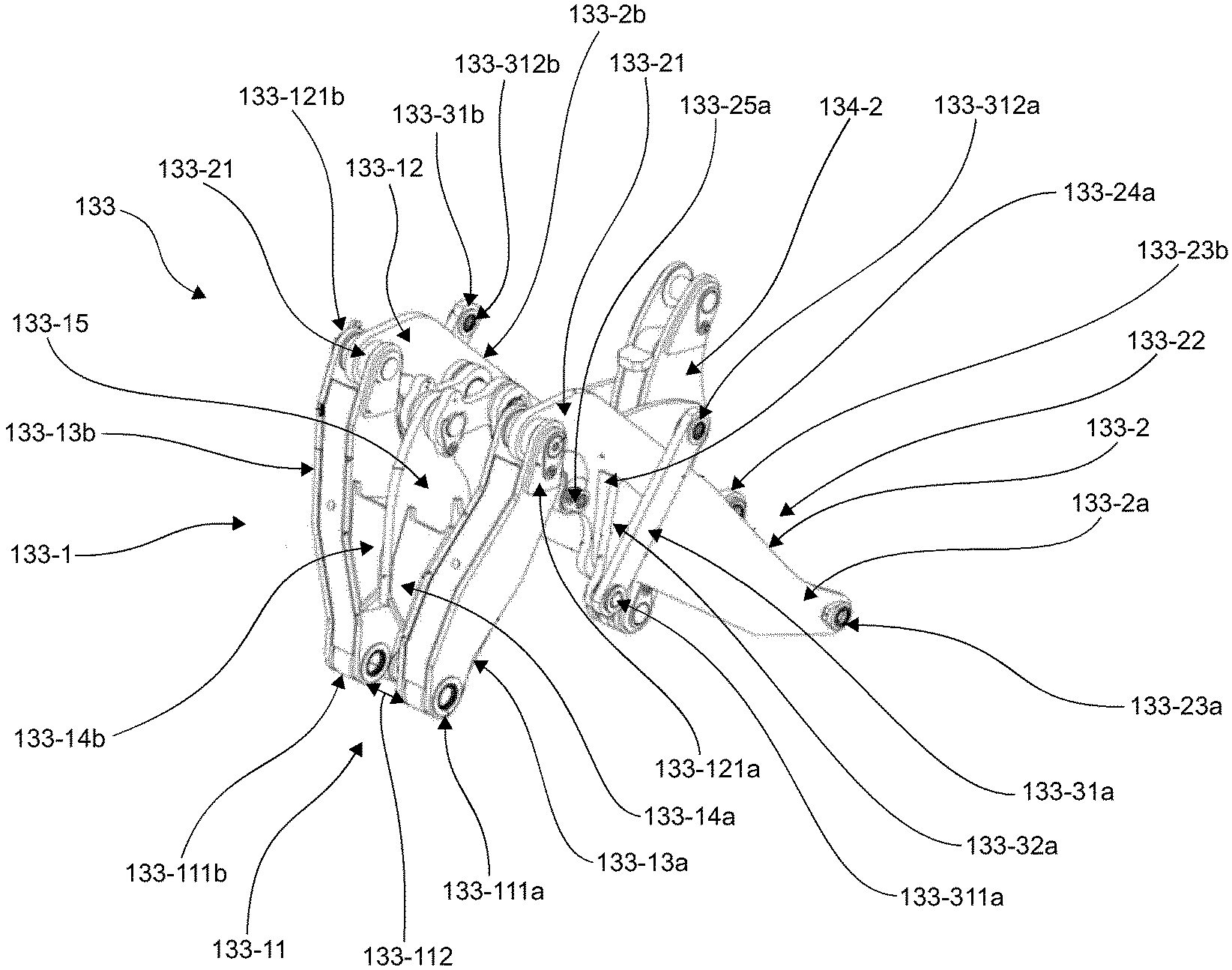
Description
TECHNICAL FIELD
[0001] The invention concerns a lifting arrangement mountable to a frame arrangement of a vertical lift wheel loader.
PRIOR ART
[0002] Vertical lift wheel loaders are construction vehicles that comprise a front frame portion and a rear frame portion, which are articulatingly interconnected for providing an articulating steering. Such loaders comprise a lifting arrangement that is supported by the front frame portion of said articulating frame arrangement and is articulated together with said front frame portion with respect to said rear frame portion upon steering.
[0003] The lifting arrangements of vertical lift loaders allow, like lifting arrangements of radial lift loaders, an equipment, e.g. a bucket, to be moved between a lowered position and a lifted position. In difference to lifting arrangements of radial lift loaders, the peculiarity of these vertical lifting arrangements is that the movement pattern of said equipment between said lowered and said lifted positions follows a substantially vertical path. This reduces the maximum distance from the bucket centroid to the front axle of the loader, thereby increasing the maximum loading capacity while maintaining the vehicle's weight.
[0004] However, lifting arrangements of vertical lift loaders are subjected to high stress, especially to torsion load. Traditional methods for stiffen of structures often result in higher weight and material accumulation.
SUMMARY OF THE INVENTION
[0005] Therefore, according to the present invention, a lifting arrangement mountable to a frame arrangement of a vertical lift wheel loader combining high torsion stiffness and light weight construction is provided.
[0006] The lifting arrangement comprises a main arm support element, a main arm, and a guiding arrangement. The main arm support element is configured to support the main arm at the frame arrangement of the vertical lift wheel loader. The main arm is configured to be connected to the main arm support element. The guiding arrangement is provided for guiding the main arm. The main arm is further configured to be connected pivotably to the frame arrangement via the main arm support element. The main arm is further configured to be connected to an equipment, e.g. a bucket, the equipment being configured to carry load. The main arm, which is subjected to (high) forces introduced through the load carried by the equipment, has therefore to be configured with a sufficient (high) torsion stiffness. Also, the main arm support element connecting the main arm to the frame arrangement has to have a sufficient high torsion stiffness.
[0007] More specifically, in contrast to radial lifting wheel loaders at vertical lift wheel loaders the main arm of the lifting arrangement is not directly coupled/fixed to a front frame portion of the frame arrangement but via an additional support element, namely the main arm support element. The same torsion stiffness as provided by the front frame portion at radial lifting wheel loaders has to be provided by the main arm support element.
[0008] That is, one end portion of the main arm support element is a frame arrangement side end portion and the other end portion of the main arm support element is a main arm side end portion. The main arm support element is pivotably mountable at the frame arrangement side end portion thereof to said frame arrangement of said vertical lift wheel loader such that said main arm side end portion of said main arm support element is movable in a direction including at least a component in a front-rear direction of said vertical lift wheel loader. Front rear-rear direction means a direction extending from a rear side of the vertical lift wheel loader to a front thereof, i.e. from a rear frame portion to the front frame portion of the wheel loader.
[0009] The main arm is further pivotably, i.e. rotatably, mounted at its mounting portion to the main arm side end portion of said main arm support link and comprises an equipment connector at its equipment connector portion which is located opposite to its mounting portion. The equipment connector is provided for connecting the above described equipment to the main arm.
[0010] The guiding arrangement is mountable to said frame arrangement of said vertical lift wheel loader for determining a movement of said main arm support element upon a pivot movement of said main arm such that upon pivoting said main arm between a lowered position and a lifted position said equipment connector is guided along a predetermined path.
[0011] The main arm support element comprises at least two longitudinal members which are interconnected by at least one connecting element. Preferably, both, the frame arrangement side end portion and the main arm side end portion are formed by end portions of the longitudinal members and the connecting element is located between these portions. The connecting element avoids relative twist/torsion of the longitudinal members. That is, by providing the connecting element a high stiffness of the whole main arm support element can be secured, i.e. the main arm support element provides a high modulus of resistance against torsion. Longitudinal member means an element formed by a rigid, solid body having a greater length than width and height. In other words, longitudinal relates to lengthwise dimension of the member, wherein the member is a rigid element. Between these two longitudinal members the connecting element is provided. Also, the connecting element is a rigid body. The term .quadrature.interconnected.quadrature. means that the two longitudinal members are spaced away from each other but connected to each other via the connecting element. The connecting element is thus connected (joined) to both longitudinal members. However, neither one of the longitudinal members nor the connection element is limited to be formed from only one component and may also be formed from a plurality of components connected to each other. .quadrature.Connecting.quadrature. or .quadrature.connection.quadrature. refers to permanently joining two or more rigid bodies each one having a geometrically determined outer shape. Different connection methods may be applied, e.g. joining by assembling, press(-in) operation, original forming, shaping, welding, soldering and/or using an adhesive. Joining by assembling may comprise inserting, mounting, hanging and/or sliding into each other. Press(-in) operation may comprise screwing, bolting, nailing and/or press fitting. Original forming is a production process where formless elements are processed to form a solid body having a geometrically defined shape and may comprise casting and/or additive manufacturing. Shaping may comprise flanging, crimping, folding, bending and/or riveting. By using welding, soldering or an adhesive two members/element are firmly bonded together. Here, soldering is a method in which two or more items, preferably metal, are joined together by melting and putting a filler metal (solder) into the joint, the filler metal having a lower melting point than the adjoining items. Soldering differs from welding in that soldering does not involve melting the work pieces. The longitudinal members and the connecting element may be formed from different material, e.g. comprising metal and/or steel.
[0012] The main arm support element may have a substantially H shape. That is, at least the two end portions of one of the pair of longitudinal members extend substantially parallel to the two end portions of the other one of the pair of longitudinal members, and the pair of longitudinal members are interconnected via the connecting element extending substantially perpendicular to the two end portions of each one of the two longitudinal members.
[0013] The main arm support element may be formed as welded structure. Here, welding is a fabrication method that joins materials, preferably metals and/or thermoplastics, by using heat to melt the parts together and allowing them to cool causing fusion.
[0014] The at least two longitudinal members and/or the at least one connecting element are formed in a box shape. The term .quadrature.box shape.quadrature. describes a three-dimensional shape of a construction element wherein base plates and side plates of the construction element comprise substantially a right angle, respectively. Preferably the box shaped construction elements are hollow bodies. Construction elements with box shape combine two advantages, namely they provide a relatively high generated surface and therefore a relatively high modulus of resistance against torsion in comparison to their low weight. More specifically, a value of the modulus of resistance against torsion of a construction element depends on a generated surface of the construction element, i.e. the modulus of resistance against torsion of the construction element raises with the generated surface thereof. Therefore, the box shape enhances the above described technical effect inherent to the lifting arrangement according to the present invention of having a high torsion stiffness with respect to its low weight. Preferably the main arm, i.e. elements forming the main arm, are also formed in the box shape.
[0015] Each of said at least two longitudinal members may comprise a pair of side plates and a connecting plate. The pair of side plates may be connected by the connecting plate such that a substantially closed profile for each of the at least two longitudinal members is provided. In other words, the pair of side plates and the connecting plate may form the substantially closed profile. The substantially closed profile provides the advantage that stress peaks in the constructional elements forming the lifting arrangement are avoided.
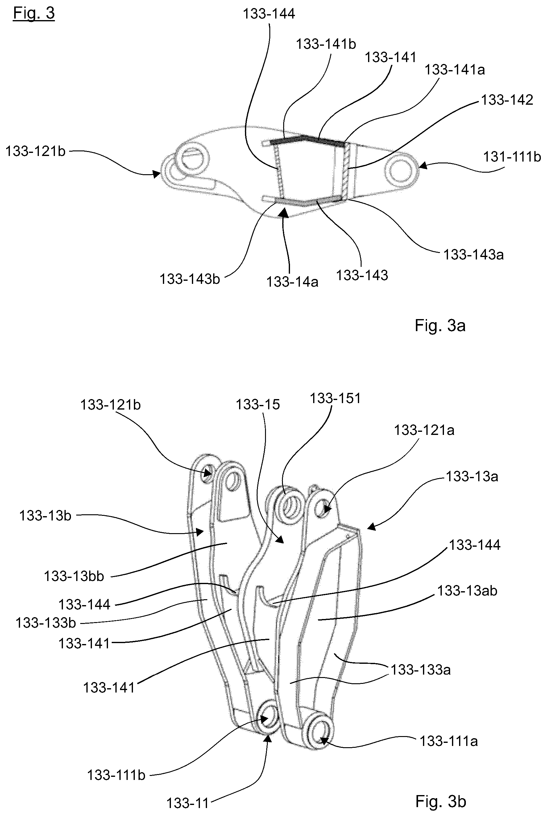
[0016] The two longitudinal members and said a least one connecting element may form a rigid body for transferring forces from said main arm to said frame arrangement. In other words, the main arm support element serves as an extension of the mounting portion of the front frame portion of the vertical lifting arrangement such that same mechanical properties at connection point to the frame arrangement may be provided for the main arm of the vertical lifting arrangement in comparison to a main arm provided for a radial lifting arrangement.
[0017] Each of said at least two longitudinal members may comprise a frame arrangement side bearing portion in the frame arrangement side end portion thereof for mounting said support element to said frame arrangement and a main arm side bearing portion in the main arm side end portion thereof for mounting said support element to said main arm. The bearing portions are both provided with a bearing such that the main arm side bearing portion can pivotably support the main arm and the frame arrangement side bearing portion can be pivotably supporter at the frame arrangement. Here, a bearing is a component that separates moving parts and takes a load. More specifically, the bearings are rotary bearings holding rotating components such as shafts or axles within a mechanical system formed by the frame arrangement. The bearing may be a plain bearing consisting of a shaft rotating in a hole. The plain bearing may be a bushing, journal bearing, sleeve bearing, rifle bearing or a composite bearing. The bearing may also be a rolling-element bearing, e.g. a ball bearing or a roller bearing, in which rolling elements placed between turning and stationary races prevent sliding friction. In the ball bearing, the rolling elements are spherical balls. In roller bearings, the rolling elements are cylindrical, taper or spherical rollers. The bearing may also be a jewel bearing, which is a plain bearing in which at least one of bearing surfaces is made of an ultrahard glassy jewel material such as sapphire to reduce friction and wear. The bearing may further be a fluid bearing, which is a noncontact bearing in which load is supported by a gas or liquid. The bearing may further be a magnetic bearing, in which the load is supported by a magnetic field, or a flexure bearing, in which the motion is supported by a load element which bends. When the bearings in the bearing portions are formed in end portions of the longitudinal members maintenance and lubrication thereof becomes easier and less cost intensive, since the end portions are easy to reach for an operator without demounting the lifting arrangement.
[0018] The frame arrangement side bearing portions may be axially spaced by a frame arrangement side distance and said main arm side bearing portions may be axially spaced by a main arm side distance. The main arm side distance may be greater than the frame arrangement side distance. The main arm side distance is preferably at least twice the frame arrangement side distance. When the frame arrangement side distance is smaller than the main arm side distance, it is possible to securely arrange all actuating components, such as a main arm actuator configured to actuate the main arm, provided in the frame arrangement between the two longitudinal members of the main arm support element and a pair of arms forming the main arm. Therefore, these actuating components which are prone to be damaged during operation of the wheel loader can be secured from outside influences such as stone chipping.
[0019] Each of the longitudinal members may be formed with a cranked configuration. Preferably the cranked configuration has a U-shape in a side view, wherein one end, which is an intermediate portion, of the cranked configuration is shorter than the other two ends connected by the one end to each other.
[0020] The connecting element may be formed by a plurality of sheet metal elements which form a substantially closed space inside. A sheet metal element is a thin part comprising metal, e.g. sheet steel. A multilayer structure is also possible. The sheet metal elements may be connected to each other in the way as described above. Using sheet metal is especially advantageously for providing relatively large surfaces with respect to weight and thus with relatively low weight high modules of resistance against torsion can be reached with sheet metal.
[0021] The main arm may comprise a pair of arms and a connecting portion. The pair of arms may be formed by substantially flat sheet metal members which are spaced from each other by the connecting portion connecting said arms to each other. As explained above, preferably the pair of arm elements and/or the connecting portion are formed in the box shape, respectively. By providing the connecting portion the same advantages as by providing the connecting element of the main arm support element can be reached.
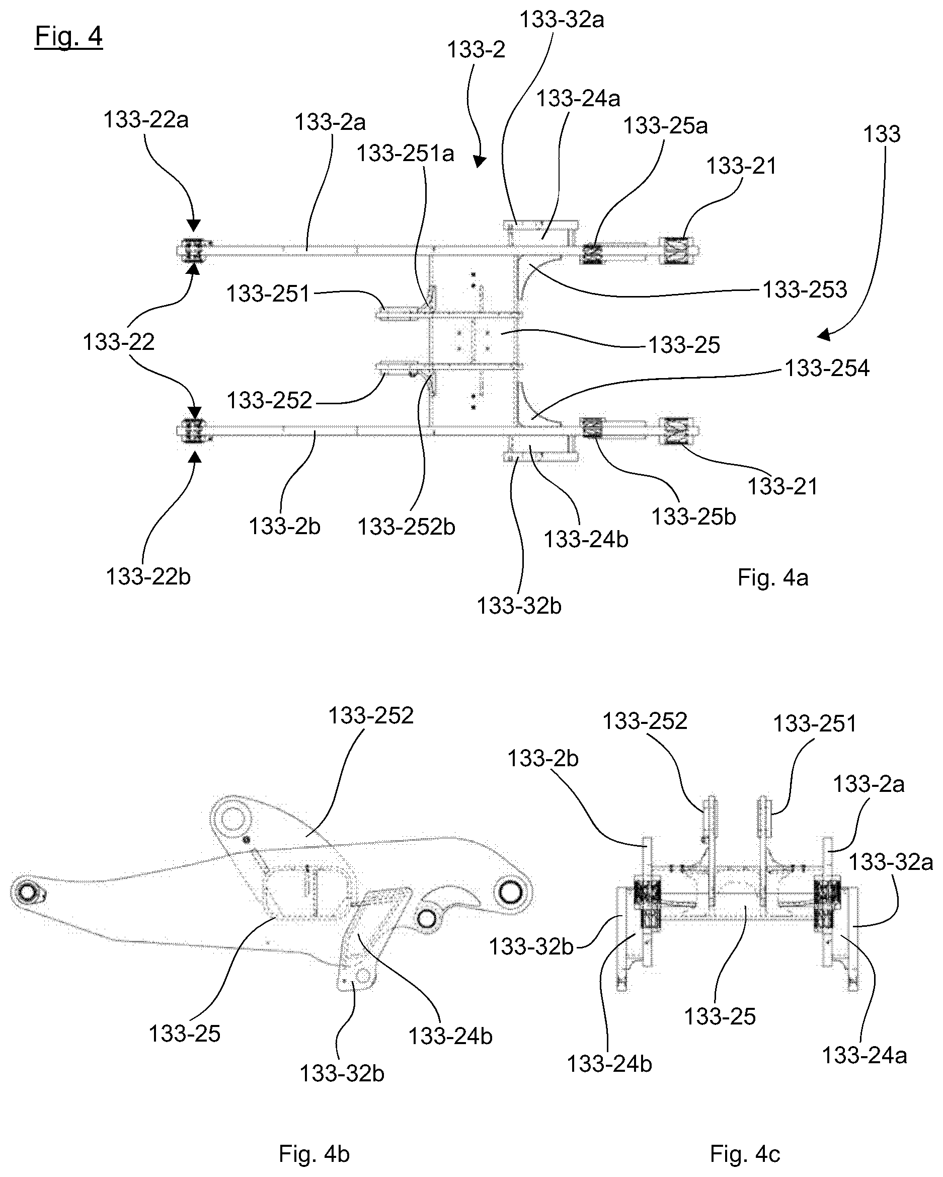
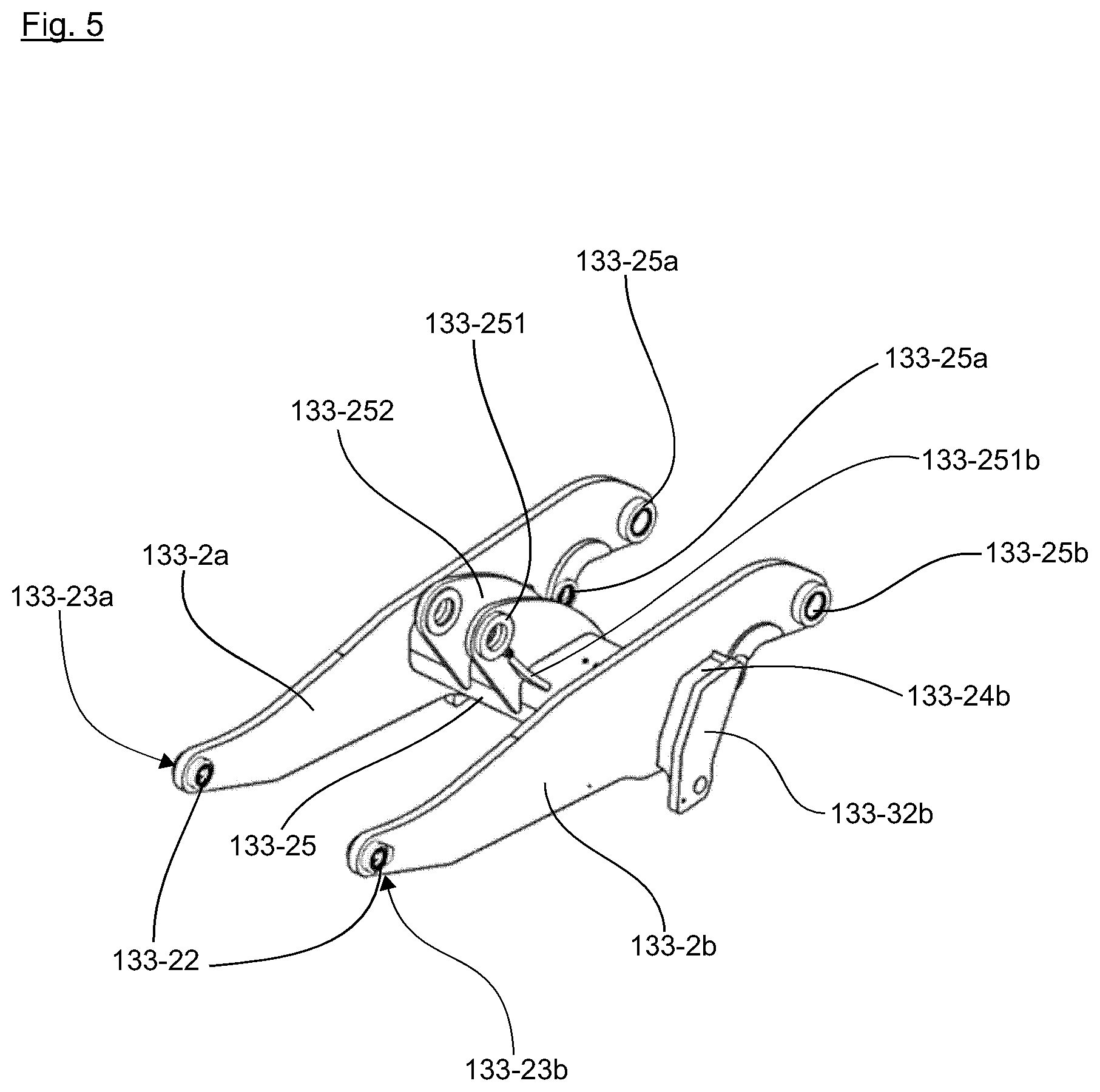
[0022] As described above, the guiding arrangement is provided for guiding the equipment connector of the main arm along the predetermined path. Therefore, the guiding arrangement may comprise at least one guiding link, at least one first guiding link mount, and at least one second guiding link mount. The at least one first guiding link mount may be provided at said arm element of the main arm. The at least one second guiding link mount may be provided at said frame arrangement. The at least one guiding link may comprise a first guiding link mount end portion and a second guiding link mount end portion. The at least one guiding link may be pivotably connected to said at least one first guiding link mount at said first guiding link mount end portion thereof and to said second guiding link mount at the second guiding link mount end portion thereof. When moving the main arm pivotably connected to main arm support element, the guiding arrangement also restricts movement of the main arm and thus, the path of the equipment connector is fixed in space by coaction of the main arm support element and the guiding arrangement.
[0023] The main arm support element may further comprise a center plate which is integrated in said connecting element and arranged between said longitudinal members. Preferably, the center plate comprises a mount for mounting a link mechanism for actuating an equipment mountable to said equipment connector. Preferably, the center plate extends in parallel to the end portions of the longitudinal members.
[0024] The main arm support element may be configured such that a torsional strength thereof is higher than a torsional strength of said main arm.
[0025] Furthermore, according to the invention, a frame arrangement may be provided. The frame arrangement comprises the above described lifting arrangement and a front frame portion. The front frame portion comprises a mounting structure. The lifting arrangement is mounted to the front frame portion via the mounting structure.
[0026] The main arm support element may be mounted pivotably to the mounting structure via the frame arrangement side bearing portion. The second guiding link mount may be connected to said front frame portion, preferably pivotably.
[0027] The above described frame arrangement may further comprise a main arm actuator connected at one end portion thereof to said front frame portion and at the other end thereof to said main arm. The main arm actuator may be provided for lifting said main arm. The main arm actuator may comprise a hydraulic and/or a pneumatic cylinder. The hydraulic cylinder (linear hydraulic motor) and the pneumatic cylinder are both a mechanical actuator that is used to give a unidirectional force through a unidirectional stroke. Both cylinders are operated by supplying a fluid to them, wherein the hydraulic cylinder is operated by using liquid, preferably (pressurized) oil, and the pneumatic cylinder is operated by using gas, preferably (pressurized) air. Both cylinders may be single-acting or double-acting. At single-acting cylinders the fluid enters through a port at one end of the cylinder, which forces a piston inside the cylinder by means of area difference at out of the cylinder. An external force, internal retraction spring or gravity returns the piston. At double-acting cylinders a port at each end of the cylinder, i.e. at each side of the piston, is supplied with the fluid for both retraction and extension of the piston which is also provided in the cylinder.
[0028] Further, the guiding arrangement may be configured to guide movements of said main arm support element and of said main arm such that said equipment connector of the main arm follows said predetermined path. The predetermined path is preferably a vertical path at least in sections of said movement upon moving said main arm between a lowered position and a lifted position and vice versa. The substantially vertical path means the movement of the equipment connector upon pivoting said main arm within a predetermined range. In particular, the predetermined range defining said substantially vertical path allows a specific deviation from a line vertically extending from the equipment connector in the lowermost position. It follows from the above that the substantially vertical path is not limited to a strictly vertically arranged line along which the equipment connector moves. Rather, any path which is limited within a range the width of which extends in the front-rear direction with respect to the wheel loader is sufficient for achieving the solution. Preferably, the deviation of the equipment connector from the vertical line extending from the equipment connector in the lowermost position is restricted to a specific deviation in the front-rear direction in order to limit the variance in a tilting momentum applied to the wheel loader which is caused by the force exerted upon lifting the load. As consequence, the tilting moment exerted to the wheel loader by the load in the intermediate position of the equipment connector can be limited to a specific extent thus enhancing the overall efficiency of the wheel loader. The substantially vertical path may be a J-shaped path, in which the equipment connector, from the lowered to the lifted position, moves initially upwards and forwards before moving essentially only straight upwards.
[0029] The front frame portion may further comprise a pair of front wheels. It would however also be possible to provide the front frame portion with any other element configured to transmit a force actuating in a moving direction of the wheel loader to road surface.
[0030] Furthermore, according to the invention, a vertical lift wheel loader may be provided. The vertical lift wheel loader comprises the above described frame arrangement, an equipment, a rear frame portion, and an articulating mechanism. The equipment is mounted to the frame arrangement via the equipment connector of the main arm of the lifting arrangement of the frame arrangement. The rear frame portion comprises a pair of rear wheels. It would however also be possible to provide the rear frame portion with any other element configured to transmit a force actuating in a moving direction of the wheel loader to road surface. The frame arrangement and the rear frame portion are connected via the articulating mechanism to each other such that the frame arrangement and the rear frame portion are relatively pivotably to each other. In other words, the wheel loader comprises an articulated frame steering/articulated steering.
BRIEF DESCRIPTION OF THE DRAWINGS
[0031] FIG. 1 shows a lifting arrangement according to an embodiment of the invention in a perspective view in a mounted state, the lifting arrangement being in a lowered position.
[0032] FIG. 2a shows a main arm support element of the lifting arrangement of FIG. 1 according to an embodiment of the present invention in a top view of in a non-mounted state.
[0033] FIG. 2b shows the main arm support element of FIG. 2a in a side view in the non-mounted state.
[0034] FIG. 2c shows the main arm support element of FIG. 2a in a further side view in the non-mounted state.
[0035] FIG. 3a is a sectional view of the main arm support element of FIG. 2a along a line A-A of FIG. 2a in the non-mounted state.
[0036] FIG. 3b shows the main arm support element of the FIG. 2a in a perspective view in the non-mounted state, wherein a side plate of a longitudinal member of the main arm support element is omitted.
[0037] FIG. 4a shows a main arm of the lifting arrangement of FIG. 1 according to an embodiment of the present invention in a top view in a non-mounted state.
[0038] FIG. 4b shows the main arm of FIG. 4a in a side view in the non-mounted state.
[0039] FIG. 4c shows the main arm of FIG. 4a in a further side view in the non-mounted state.
[0040] FIG. 5 shows the main arm of FIG. 4a in a perspective view in the non-mounted state.
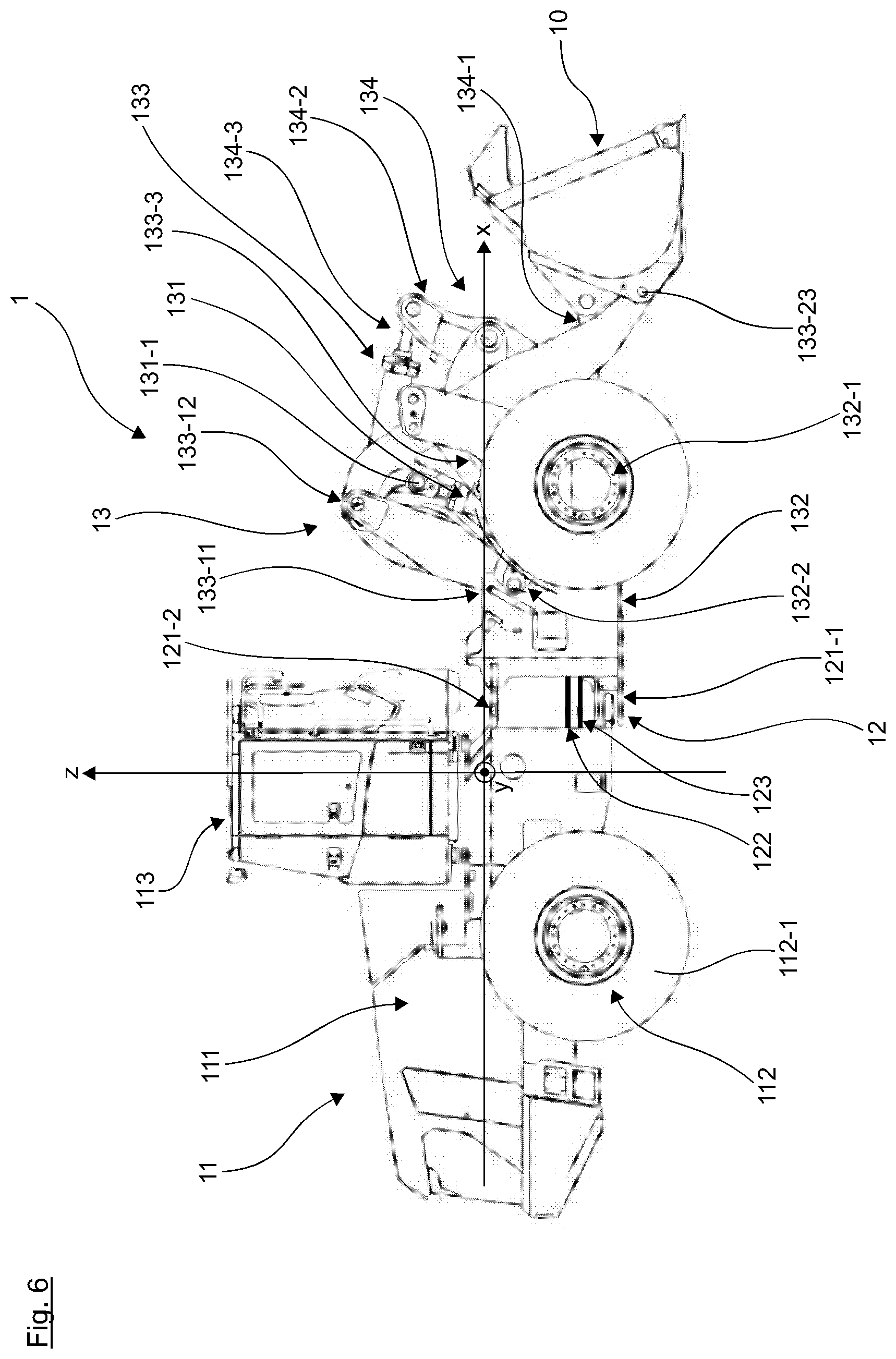
[0041] FIG. 6 shows a side view of a vertical lift wheel loader according an embodiment of the invention with the lifting arrangement of FIG. 1 being in a lowered position in the mounted state.
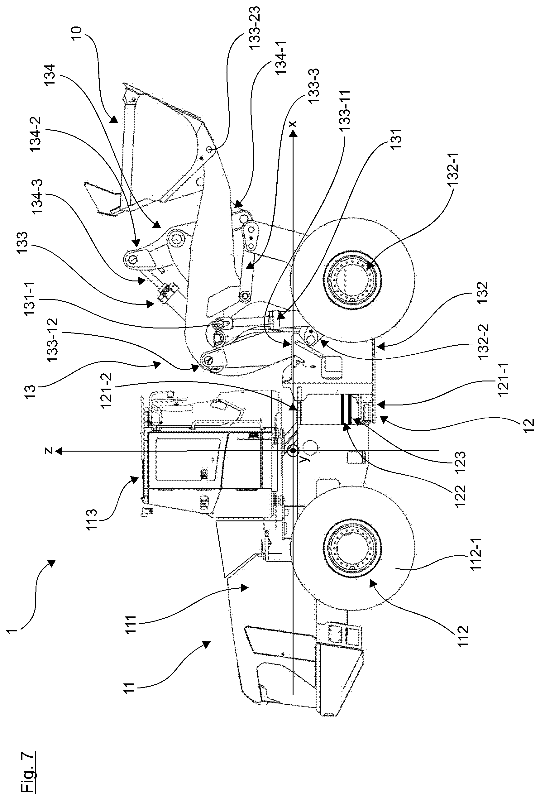
[0042] FIG. 7 shows a side view of the vertical lift wheel loader of FIG. 6 with the lifting arrangement being in an intermediate position in the mounted state.
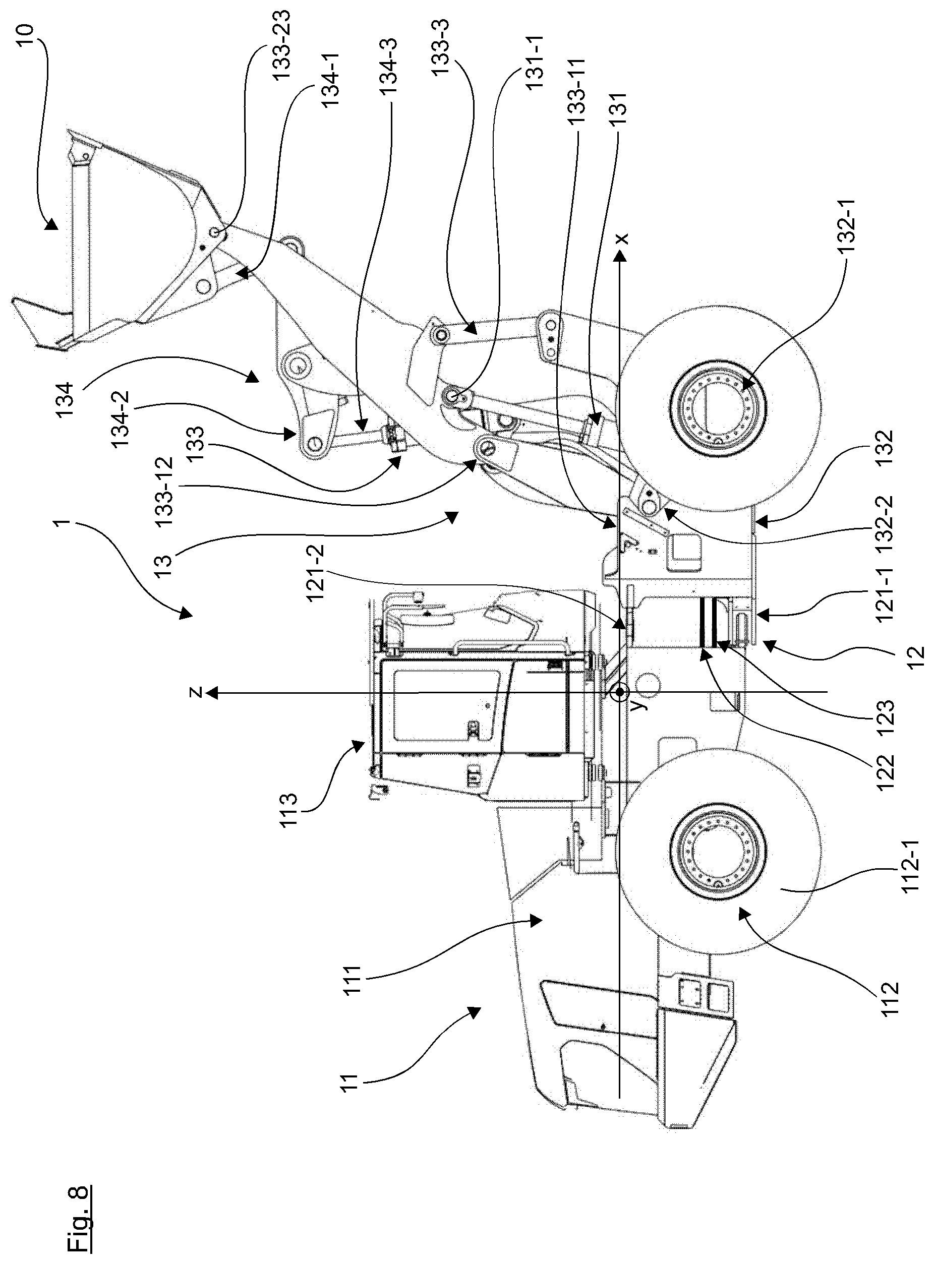
[0043] FIG. 8 shows a side view of the vertical lift wheel loader of FIG. 6 with a lifting arrangement being in an upper position in the mounted state.
DETAILED DESCRIPTION OF EMBODIMENTS
[0044] Embodiments of the present invention are subsequently described with reference to the attached FIGS. 1 to 8.
[0045] Description of positional relations of constructional elements of the vertical lift wheel loader made with respect to FIGS. 1, and 6 to 8 correspond to a mounted state of the respective constructional elements. Description of positional relations of constructional elements of the vertical lift wheel loader made with respect to FIGS. 2a-c, 3a, b, 4a-c, and 5 correspond to a non-mounted state of the respective constructional elements.
[0046] Directions X (driving direction), Y (width direction), and Z (vertical direction), which will be defined in following description, relate to the mounted state of the vertical lift wheel loader 1.
[0047] In following part of the description, the vertical lift wheel loader will be described with references to FIGS. 1, and 6 to 8.
[0048] FIG. 6 shows a side view of the vertical lift wheel loader 1 according an embodiment of the invention with a lifting arrangement 133 being in a lowered position in a mounted state. FIG. 7 shows a side view of the vertical lift wheel loader 1 of FIG. 6 with the lifting arrangement 133 being in an intermediate position in the mounted state. FIG. 8 shows a side view of the vertical lift wheel loader 1 of FIG. 6 with the lifting arrangement 133 being in an upper (lifted) position in the mounted state. FIG. 1 shows the lifting arrangement 133 of FIG. 6 in the mounted state, the lifting arrangement 133 being in the lowered position, i.e. FIG. 1 shows the lifting arrangement 133 as extracted from the FIG. 6.
[0049] As illustrated in FIGS. 6 to 8, the vertical lift wheel loader 1 comprises an equipment 10, a rear frame portion 11, an articulating mechanism 12, and a frame arrangement 13.
[0050] The rear frame portion 11 is connected to the frame arrangement 13 via the articulating mechanism 12 such that the rear frame portion 11 and the frame arrangement 13 can rotate relatively to each other about a vertical axis being substantially parallel to a vertical direction Z. The vertical direction Z being substantially perpendicular to a road surface on which the wheel loader 1 is located.
[0051] The rear frame portion 11 comprises an engine compartment 111, a rear axle assembly 112, a drive train (not shown), and an operator's cab 113. The engine compartment 111 is connected to the rear axle assembly 112 via the drive train. The drive train is configured to transmit power from the engine compartment 111 to the rear axle assembly 112. The engine compartment 111 comprises a combustion engine and/or an electric motor for generating and supplying the power (torque) to the drive train. The rear axle assembly 112 comprises rear wheels 112-1 and is thus configured to transmit the power received from the engine compartment 111 to the road surface such that the wheel loader 1 is moved in a driving direction X. The driving direction X being substantially perpendicular to the vertical direction Z and extending from the rear frame portion 11 to the frame arrangement 13. The driving direction X extends in a front-rear direction of the wheel loader 1. The operator's cab 113 is provided at the rear frame portion 11 and is located above the engine compartment 111 in the driving vertical direction Z. The operator's cab 113 is provided for an operator for inputting control signals for controlling the wheel loader 1.
[0052] The articulating mechanism 12 comprises a pair of bearings 121-1, 121-2, a pair of steering cylinders 122, and control lines 123. The pair of bearings 121-1, 121-2 is provided offset in the vertical direction Z and substantially in middle of a width direction Y of the wheel loader. The width direction Y is perpendicular to the driving direction X as well as to the vertical direction Z. Both, the width direction Y and the driving direction X, are substantially parallel to the road surface. Each bearing of the pair of bearings 121-1, 121-2 comprises a male and a female part, wherein the male part is fixed to the rear frame portion 11 and the female part is fixed to the frame arrangement 13, or vice versa. The pair of steering cylinders 122 extend from the rear frame portion 11 to the frame arrangement 13 substantially perpendicular to the vertical direction Z. By retracting one cylinder of the pair of steering cylinders 122 and extending the other one of the pair of the steering cylinders 122, the rear frame portion 11 and the frame arrangement 13 rotate relatively to each other about the vertical axis Z. In other words, steering of the wheel loader 1 is carried out by retracting and extending the steering cylinders 122. The control lines 123 extend in the driving direction X from the rear frame portion 11 to the frame arrangement 12. The control lines 123 are provided for supplying control signals from the rear frame portion 11 to the frame arrangement 13, the control signals may also correspond to the control signals input from the operator.
[0053] The frame arrangement 13 comprises a main arm actuator 131, a front frame portion 132, the lifting arrangement 133, and a tilting arrangement 134.
[0054] The front frame portion 132 is connected via the pair of bearings 121-1, 121-2 to the rear frame portion 11 in the manner as described above and forms a first part of the frame arrangement 13 in the driving direction X. The front frame portion 132 comprises a pair of front wheels 132-1 and a mounting structure 132-2. The pair of front wheels 132-1 are connected to the engine compartment 111 via a part of the drive train (not shown) extending from the rear frame portion 11 to an axle (not shown) connecting the pair of front wheels 132-1 to each other. Therefore, the power can not only be transmitted to the road surface via the rear wheels 112-1 but also via the pair of front wheels 132-1. The mounting structure 132-2 is configured as a male part such that the lifting arrangement 133 can be connected to the front frame portion 132 via the mounting structure 132-2.
[0055] The lifting arrangement 133 comprises a main arm support element 133-1, a main arm 133-2, and a guiding arrangement 133-3.
[0056] The main arm support element 133-1 comprises a frame arrangement side end portion 133-11, a main arm side end portion 133-12, a pair of longitudinal members 133-13a, 133-13b, a pair of connecting elements 133-14a, 133-14b, and a center plate 133-15.
[0057] The two longitudinal members forming the pair of longitudinal members 133-13a, 133-13b are connected to each other via the two connecting elements 133-14a, 133-14b forming the pair of connecting elements 133-14a, 133-14b and the center plate 113-15. In the lowered position of the lifting arrangement 133 the pair of longitudinal members 133-13a, 133-13b extends substantially in the vertical direction Z. The frame arrangement side end portion 133-11 is formed by end sides of the pair of longitudinal members 133-13a, 133-13b, respectively. The main arm side end portion 133-12 is formed by the other end sides of the pair of longitudinal members 133-13a, 133-13b, respectively. In the vertical direction Z, the main arm side end portion 133-12 is located above the frame arrangement side end portion 133-11. In the driving direction X in the lowered position of the lifting arrangement 133, the main arm side end portion 133-12 is located farer away from the rear frame portion 11 than the frame arrangement side end portion 133-11. In other words, in the lowered position of the lifting arrangement 133, the main arm support element 133-1 is inclined in the driving direction X. The main arm support element 133-1 is connected to the mounting structure 132-2 of the front frame portion 132 at the frame arrangement side end portion 133-11. The main arm support element 133-1 is connected to the main arm 133-2 of the front frame portion 132 at the main arm side end portion 133-12.
[0058] More specifically, the frame arrangement side end portion 133-11 comprises two bearing portions, i.e. a pair of frame arrangement side bearing portions 133-111a, 133-111b. One frame arrangement side bearing portion 133-111a of the pair of frame arrangement side bearing portions 133-111a, 133-111b is provided at one longitudinal member 133-13a and the other frame arrangement side bearing portion 133-111b of the pair of frame arrangement side bearing portions 133-111a, 133-111b is provided at the other longitudinal member 133-13b. Each one of the frame arrangement side bearing portions 133-111a, 133-111b comprises a bearing for rotatably supporting an axle (not shown) of the mounting structure 132-2 of the front frame portion 132. The axle of the mounting structure 132-2 penetrates through both longitudinal members 133-13a, 133-13b in the width direction Y and is fixed to the front frame portion 132. The axle is not limited to a continuously and may be formed by two independent parts. In conclusion, the main arm support element 133-1 is pivotably mounted at the frame arrangement side end portion 133-11 thereof to the frame arrangement 13 of the vertical lift wheel loader 1. Therefore, when the main arm support element 133-1 is moved, the main arm side end portion 133-12 of the main arm support element 133-1 describes a substantially circular path in a plane formed by the driving direction X and the vertical direction Z, i.e. in the side view of the vertical lift wheel loader 1, wherein a center of the circular path is formed by the axle of the mounting structure 132-2 of the front frame portion 132.
[0059] Also the main arm side end portion 133-12 comprises two bearing portions, i.e. a pair of main arm side bearing portions 133-121a, 133-121b which will be described in further detail below in connection with the main arm 133-2.
[0060] The main arm 133-2 is comprises two arms 133-2a, 133-2b, a mounting portion 133-21 and an equipment connector portion 133-22. Each one of the arms 133-2a, 133-2b comprises an equipment connector 133-23a, 133-23b, an arm element 133-24a, 133-24b, and a main arm actuator connection portion 132-25a, 132-25b.
[0061] The arms 133-2a, 133-2b of the main arm 133-2 extend substantially parallel to a plane formed by the driving direction X and the vertical direction Z. The arms 133-2a, 133-2b are connected to each other via the arm connecting element 133-25 (see also FIG. 4).
[0062] The mounting portion 133-21 of the main arm 133-2 and the equipment connector portion form end portions of the main arm 133-2, respectively. The equipment connector portion 133-22 is formed by the equipment connectors 133-23a, 133-23b of the arms 133a, 133b of the main arm 133-2, respectively. Each one of the equipment connectors 133-23a, 133-23b comprises a bearing supporting an axle extending through a through hole formed in the equipment 10 for rotatably supporting the equipment 10 connected to the main arm 133-2. In the lowered position of the lifting arrangement 133, the mounting portion 133-21 of the main arm 133-2 is located closer to the rear frame portion 11 than the equipment connector portion 133-22 in the driving direction X. In the lowered position of the lifting arrangement 133, the mounting portion 133-21 of the main arm 133-2 is located above the equipment connector portion 133-22 in the vertical direction Z. The mounting portion 133-21 of the main arm 133-2 is thus provided for connecting the main arm 133-2 to the main arm support element 133-1 and the equipment connector portion 133-22 is provided for connecting the equipment 10 to the main arm 133-2.
[0063] More specifically, one main arm side bearing portion 133-121a of the pair of main arm side bearing portions 133-121a, 133-121b is provided at one longitudinal member 133-13a and the other main arm side bearing portions 133-121b of the pair of main arm side bearing portions 133-121a, 133-121b is provided at the other longitudinal member 133-13b of the main arm support element 133-1. Each one of the main arm side bearing portions 133-121a, 133-121b comprises a bearing for rotatably (pivotably) supporting the main arm 133-2. In the preferred embodiment shown in FIG. 1 the main arm side bearing portion 133-121a, 133-121b is a female part housing a mounting portion 133-21 of the main arm 133-2 which is a male part, respectively. However, also the other way round would be possible, i.e. the mounting portion 133-21 of the main arm 133-2 is a female part housing the main arm side bearing portions 133-121a, 133-121b being a male part (not shown). The bearings of the main arm side bearing portion 133-121a, 133-121b rotatably supports an axle extending substantially in the width direction Y and penetrating through the mounting portion 133-21 of the main arm 133-2. Thus, the main arm 133-2 is pivotably mounted at its mounting portion 133-21 to the main arm side end portion 133-12 of said main arm support link 133-1, wherein the axles supported by the bearings of the main arm side bearing portions 133-121a, 133-121b are a center of a circular path described by the main arm 133-2 when moving. More specifically, when the main arm 133-2 is moved, the equipment connector portion 133-22 of the main arm 133-2, located at the opposite end of the main arm 133-2 than the mounting portion 133-21 of the main arm 133-2, describes a substantially circular path around the main arm side end portion 133-12 of the main arm support element 133-1 in the plane formed by the driving direction X and the vertical direction Z. The center of the circular path of the equipment connector portion 133-22 is formed by the axle supported by the bearings of the main arm side bearing portions 133-121a, 133-121b, respectively.
[0064] Furthermore, the frame arrangement side bearing portions 133-111a, 133-111b and the main arm side bearing portions 133-121a, 133-121b are, as described above, spaced away from each other in the width direction Y. More specifically, the frame arrangement side bearing portions 133-111a, 133-111b of the main arm support element 133-1 are axially spaced by a frame arrangement side distance 133-112 and the main arm side bearing portions 133-121a, 133-121b of the main arm support element 133-1 are axially spaced by a main arm side distance 133-122. The main arm side distance 133-122 is greater than the frame arrangement side distance 133-112 (see also FIG. 2a). Preferably the main arm side distance 133-122 is twice the frame arrangement side distance 133-112. The frame arrangement side distance 133-112 is the distance between the frame arrangement side bearing portions 133-111a, 133-111b and the main arm side distance 133-122 is the distance between the main arm side bearing portions 133-121a, 133-121b, wherein both distances extend substantially in the width direction Y.
[0065] However, the main arm 133-2 is not only connected to the main arm support element 133-1 but also to the guiding arrangement 133-3. Therefore, the arm element 133-24a, 133-24b of the main arm 133-2 are provided at intermediate portions of the arms 133-2a, 133-2b of the main arm 133-2 and protrude from the arms 133-2a, 133-2b of the main arm 133-2 in the width direction Y in the lowered position of the lifting arrangement 133, respectively. The arm elements 133-24a, 133-24b provide a mounting surface for the guiding arrangement 133-3. The arm elements 133-24a, 133-24b are provided for connecting the main arm 133-2 to the guiding arrangement 133-3 as will be discussed in detail below.
[0066] The guiding arrangement 133-3 provides a guiding link 133-31a, 133-31b, a first guiding link mount 133-32a, 133-32b, and a second guiding link mount 133-33a, 133-33b for each arm 133-2a, 133-2b of the main arm 133-2, respectively. In conclusion, the guiding arrangement 133-3 comprises two guiding links 133-31a, 133-31b, two first guiding link mounts 133-32a, 133-32b, and two second guiding link mounts 133-33a, 133-33b. Each one of the guiding links 133-31a, 133-31b comprises a first guiding link mount end portion 133-311a, 133-311b and a second guiding link mount end portion 133-312a, 133-312b, respectively.
[0067] The first guiding link mounts 133-32a; 133-32b are provided at, i.e. fixed to, the respective arm element 133-24a, 133-24b. The second guiding link mounts 133-33a, 133-33b are provided at, i.e. fixed to, respective portions of the front frame portion 132 of the frame arrangement 13. The first guiding link mounts 133-32a, 133-32b have substantially the same outer shape than the arm elements 133-24a, 133-24b of the main arm 133-2 beside a protrusion protruding from the arm element 133-24a, 133-24b substantially in the vertical direction Z in the lowered position of the lifting arrangement 133, respectively. The guiding links 133-31a, 133-31b are pivotably connected to the first guiding link mounts 133-32a, 133-32b via the first guiding link mount end portions 133-311a, 133-311b thereof as well as to the second guiding link mounts 133-33a, 133-33b via the second guiding link mount end portion 133-312a, 133-312b thereof, respectively. Since the second guiding link mount end portion 133-312a, 133-312b are fixed to and rotatably supported by the front frame portion 132 via the second guiding link mounts 133-33a, 133-33b, when moving the guiding links 133-31a, 133-31b, the first guiding link mount end portions 133-311a, 133-311b are forced on a circular path around the second guiding link mount end portion 133-312a, 133-312b. Moreover, since the first guiding link mount end portions 133-311a, 133-311b are fixed to and rotatably supported by the main arm 133-2 via the first guiding link mount 133-32a, 133-32b and the arm element 133-24a, 133-24b, also a movement of the equipment connector portion 133-22 of the main arm 133-2 is limited by the guiding arrangement 133-3. As described above, the mounting portion 133-21 of the main arm 133-2 is also connected to the mounting structure 132-2 of the front frame portion 132 via the main arm support element 133-1, and thus the mounting portion 133-21 of the main arm 133-2 is forced on a circular path around the mounting structure of the front frame portion 132. Thus, the movement of the equipment connector portion 133-22 of the main arm 133-2 is further limited by the main arm support element 133-1. By appropriate choice of dimensions of the parts forming the frame arrangement 13, when moving the main arm 133-2 from the lowered to the upper position of the lifting arrangement 133, the equipment connector portion 133-22 of the main arm 133-2 is forced on a predetermined path being a substantially vertical path, as seen in FIGS. 6 to 8.
[0068] The movement of the main arm 133-2 from the lowered to the upper position of the lifting arrangement 133 is reached by expanding and contracting the main arm actuator 131 which is connected to the main arm 133-2. The main arm actuator 131 is provided under the main arm 133-2 in the vertical direction Z of the main arm 133-2 and comprises two actuators. The main arm actuator 131 comprises a first portion 131-1 at one end therefore and a second portion (not shown) on the other end thereof. Each one of the actuators of the main arm actuator 133 first portion 131-1 of the main arm actuator 131 is connected to the respective main arm actuator connection portion 133-25a, 133-25b of the main arm 132-2. One main arm actuator connection portion 133-25a, 133-25b is provided at each arm 133-2a, 133-2b between the arm element 133-24a, 133-24b and the mounting portion 133-21 of the main arm 133-2 in the driving direction X in the lowered position of the lifting arrangement 133, respectively. The second portion of the main arm actuator 131 is connected to the front frame portion 132. The first portion 131-1 of the main arm actuator 131 is located above the second portion of the main arm actuator 131-1 in the vertical direction Z in the lowered position of the lifting arrangement 133.
[0069] The lowered position of the lifting arrangement 133, as seen in FIG. 6, thereby refers to a state, where the equipment connector portion 133-22 of the main arm 133-2 is located in a lowermost position in the vertical direction Z, i.e. nearest position to the road surface. In the lowered position of the lifting arrangement 133 the main arm actuator 131 is substantially fully retracted.
[0070] The upper position of the lifting arrangement 133, as seen in FIG. 8, thereby refers to a state, where the equipment connector portion 133-22 of the main arm 133-2 is located in an uppermost position in the vertical direction Z, i.e. a position furthest to the road surface. In the upper position of the lifting arrangement 133 the main arm actuator 131 is substantially fully expanded.
[0071] The intermediate position of the lifting arrangement 133, as seen in FIG. 7, thereby refers to a state, where the equipment connector portion 133-22 of the main arm 133-2 is located between the uppermost position and the lowermost position thereof in the vertical direction Z, i.e. a position between the uppermost and the lowermost position of the equipment connector portion 133-22 of the main arm 133-2 with respect to the road surface. In the intermediate position of the lifting arrangement 133 the main arm actuator 131 is not substantially fully retracted but also not substantially fully expanded, i.e. the main arm actuator 131 is an intermediate state.
[0072] As outlined above, the frame arrangement 13 further comprises the tilting arrangement 134 which is provided between the arms 133-2a, 133-2b of the main arm 133-2. The tilting arrangement 134 comprises a tilting mount 134-1, a tilting connector 134-2, and a tilting actuator 134-3.
[0073] The tilting actuator 134-3 is pivotably connected at one end thereof to the center plate 133-15 of the main arm support element 133-1 and at the other end thereof to the tilting connector 134-2. The center plate 133-15 is sandwiched between the pair of connecting elements 133-14a, 133-14b. The tilting actuator 134-3 is provided at least partly above the main 133-2 in the vertical direction Z in the lowered position of the lifting arrangement 133. The tilting connector 134-2 is pivotably connected at one end thereof to the tilting actuator 134-3 and at the other end thereof to the tilting mount 134-1. The tilting connector 134-2 is further pivotably connected to tilting connector portions 133-251, 133-252 of the arm connecting element 133-25 of the main arm 133-2 (see also FIG. 4a). The tilting mount 134-1 is connected pivotably to the tilting connector 134-2 and at the other end thereof to the equipment 10. The tilting mount 134-1 is provided at least partly under the main 133-2 at the one end thereof and above the main arm 133-2 at the other end thereof in the vertical direction Z in the mounted state in the lowered position of the main arm 133-2. In conclusion, the tilting arrangement 134 has substantially a Z-shape in the plane formed by the driving direction X and the vertical direction Z in the lowered position of the lifting arrangement 133. Therefore, by expanding and retracting the tilting actuator 134-3, tilting of the equipment 10 can be controlled.
[0074] In the following, the main arm support element 133-1 will be described in further detail with reference to FIGS. 2a-c, and 3a, b.
[0075] The main arm support element 133-1 is formed as welded structure and comprises the two longitudinal members 133-13a, 133-13b which are interconnected by the two connecting elements 133-14a, 133-14b. The center plate 133-15 is located between the two connecting elements 133-14a, 133-14b. In other words, the main arm support element 133-1 has a substantially H shape. Both, the two longitudinal members 133-13a, 133-13b and the connecting elements 133-14a, 133-14b are formed in a box shape and by a plurality of sheet metal elements which form a substantially closed space inside. More specifically, each one of the two longitudinal member 133-13a, 133-13b comprises two side plates 133-13aa, 133-13ab, 133-13ba, 133-13bb and two connecting plates 133-133a, 133-133b. One of the side plates 133-13aa, 133-13ba of each longitudinal member 133-13a, 133-13b is connected to the respective connecting element 133-14, 133-14b connected to the respective longitudinal member 133-13a, 133-13b, wherein the other side plate 133-13ab, 133-13bb forms an outside of the respective longitudinal member 133-13a, 133-13b. The side plates 133-13aa, 133-13ab, 133-13ba, 133-13bb are connected to each other via the connecting plates 133-133a, 133-133b, respectively. In conclusion, each one of the two longitudinal members 133-13a, 133-13b has a closed profile and is formed with a cranked configuration. With the above described structure, the two longitudinal members 133-13a, 133-13b, connected via the two connecting elements 133-14a, 133-14b and the center plate 133-15 to each other, form a rigid body for transferring forces from the main arm 133-2 to the front frame portion 132.
[0076] The mount 133-151 of the center plate 133-15 for connecting the main arm support element 133-1 to the tilting arrangement 134 is substantially housed between the two longitudinal members 133-13a. 133-13b, and therefore the bearing of the mount 133-151 of the center plate 133-15 is protected from outer forces such as stone-chipping and so on.
[0077] The longitudinal member 133-13a, 133-13b is divided in three sub portions, i.e. the main arm side bearing portion 133-121a, 133-121b, the frame arrangement side bearing portion 133-111a, 133-111b and an intermediate portion connecting them. At the main arm side bearing portion 133-121a, 133-121b the pairs of side plates 133-13aa, 133-13ab, 133-13ba, 133-13bb forming the longitudinal members 133-13a, 133-13b are substantially parallel to the center plate 133-15. At the frame arrangement side bearing portion 133-111a, 133-111b the pairs of side plates 133-13aa, 133-13ab, 133-13ba, 133-13bb forming the longitudinal members 133-13a, 133-13b are substantially parallel to the center plate 133-15. Since, as explained above, the main arm side distance 133-122 is smaller than the frame arrangement side distance 133-112 and both, the frame arrangement side bearing portion 133-111a, 133-111b and the main arm side bearing portion 133-121a, 133-121b extend substantially parallel to each other, the intermediate portion connecting the frame arrangement side bearing portion 133-111a, 133-111b and the main arm side bearing portion 133-121a, 133-121b is inclined with respect to center plate as well as the frame arrangement side bearing portion 133-111a, 133-111b and the main arm side bearing portion 133-121a, 133-121b. The connecting elements 133-14a, 133-14b are connected to the inclined intermediate portions of the longitudinal members 133-13a, 133-13b preferably by welding.
[0078] Referring especially to the FIG. 3a showing a sectional view of the main arm support element 133-1 along a line A-A of the FIG. 2a, and to the FIG. 3b showing the main arm support element 133-1 of the FIG. 2a in a perspective view wherein the side plate 133-13ab of the longitudinal member 133-13a is omitted. The following explanations are directed to the connecting element 133-14a and the longitudinal member 133-13a but however apply also to the other connecting element 133-14b and the longitudinal member 133-13b. As can be gathered from FIG. 3a the connecting element 133-14a, which is formed in the above described box shape, comprises four plates, i.e. a first plate 133-141, a second plate 133-141, a third plate 133-143, and a fourth plate 133-144. As seen in FIG. 3, the four plates 133-141, 133-142, 133-143, 133-144 are connected to each other such that they the connecting element 133-14a has a substantially four-sided (quadrangular) outer shape in a cross section thereof (see FIG. 3a). The first and third plates 133-141, 133-143 extend substantially from the frame arrangement side bearing portion 133-111a, 133-111b to the main arm side bearing portion 133-121a, 133-121b of the longitudinal member 133-13a. Both, the first and third plates 133-141, 133-143, comprise a kink dividing the first and third plates 133-141, 133-143 in two sub portions 133-141a, 133-141b, 133-143a, 133-143b, respectively, wherein these two sub portions 133-141a, 133-141b, 133-143a, 133-143b are inclined relatively to each other. Furthermore, the first and third plates 133-141, 133-143 abut against the second plate 133-142 on their sub portion 133-141a, 133-143a which is located closer to the frame arrangement side bearing portion 133-111b than to the main arm side bearing portion 133-121, respectively. The sub portions 133-141b, 133-143b which are located closer to the main arm side bearing portion 133-121 than to the frame arrangement side bearing portion 133-111b sandwich, i.e. house, the fourth plate 133-144 there between. Preferably both, the first and third plates 133-141, 133-143, but at least the first plate 133-141 comprises a rounded end portion on its end portion facing the main arm side bearing portion 133-121. These rounded end portions protrude from the second end plate in a direction to the main arm bearing portion 133-121 and therefore provide the technical effect that tension peaks at the connecting element 133-14b are avoided. Moreover, as can be gathered from FIG. 3b, the second plate 133-142 is inclined with respect to the side plate 133-13ab and thus forces acting on the center plate 133-15, e.g. via the mount 133-151 of the center plate 133-155 connected to the tilting arrangement 134, can be introduced in an advantageously manner into the longitudinal member 133-13a and thus into the front frame portion 132 via the mounting structure of the front frame portion 132.
[0079] Furthermore, as becomes clear from FIG. 3b, the connecting plates 133-133a, 133-133b connecting the pair of side plates 133-13aa, 133-13ab, 133-13ba, 133-13bb of the pair of longitudinal members 133-13a, 133-13b, respectively, are formed by welding (preferably by providing a fillet weld) two bent metal sheets onto inner sides of the pair of side plates 133-13aa, 133-13ab, 133-13ba, 133-13bb, the inner sides facing each other. One end portion of each one of the connecting plates 133-133a, 133-133b is connected to a bearing housing provided for the bearing of the frame arrangement side bearing portion 133-111a, 133-111b and the other end portion faces the main arm side end portion 133-12 and forms a border between the intermediate portion and the main arm side bearing portion 133-121a, 133-121b of the respective longitudinal member 113-13a, 113-13b. As outlined above the longitudinal members 133-13a, 133-13b have a closed profile. Thus at the one end portion of each one of the connecting plates 133-133a, 133-133b which is connected to the bearing housing provided for the bearing of the frame arrangement side bearing portion 133-111a, 133-111b the two bent metal sheets forming the respective connecting plate 133-133a, 133-133b are welded to the bearing housing. At the other end portion facing the main arm side end portion 133-12 the two bent metal sheets forming the respective connecting plate 133-133a, 133-133b are also connected to each other via welding.
[0080] In the following, the configuration of the main arm 133-2 will be described in further detail with reference to FIGS. 4a-c, and 5.
[0081] As described above, the main arm 133-2 comprises the arm connecting element 133-25 sandwiched between 133-2a, 133-2b and connecting the arms 133-2a, 133-2b to each other. The arm connecting element 133-25 is provided between the equipment connectors 133-23a, 133-23b forming the equipment connector portion 133-23 and the main arm actuator connection portions 133-25a, 133-25b. The arm connecting element 133-25 comprises the tilting connector portion 133-251, 133-252 and rounded connecting elements 133-253, 133-254. The arm connecting element 133-25 is connected to the arms 133-2a, 133-2b also via the rounded connecting elements 133-253, 133-254, respectively. The rounded connecting elements 133-253, 133-254 provide the technical effect that torsion peaks between the arm connecting element 133-25 and the arms 133-2a, 133-2b are avoided and they support the arm connecting element 133-25 further at the arms 133-2a, 133-2b. As seen in FIGS. 4b and 5 the connecting element 133-25 has rounded corners and thus also torsion peaks inside the connecting element 133-25 itself are avoided. Preferably the connecting element 133-25 is formed from two parts, i.e. an upper and a lower half, welded together, as can be gathered from FIG. 5, thus having a box shape. The tilting connector portions 133-251, 133-252 are provided on the arm connecting element 133-25 for connecting the main arm 133-2 to the tilting connector 134-2 of the tilting arrangement. Since forces acting on the tilting arrangement 134 are transferred via the tilting connector 134-2 and the tilting connector portions 133-251, 133-252 also the tilting connector portions 133-251, 133-252 are provided with rounded connecting elements 133-251a, 133-252b. The rounded connecting elements 133-251a, 133-252b provide the technical effect that torsion peaks between the arm connecting element 133-25 and the tilting connector portions 133-251, 133-252 are avoided and they support the tilting connector portions 133-251, 133-252 further at the arm connecting element 133-25.
[0082] The arm elements 133-24a, 133-24b connected to both arms 133-2a, 133-2b, respectively, are provided for connecting the main arm 133-2 to the guiding arrangement 133-3 via the guiding links 133-31a, 133-31b. Each one of the arm elements 133-24a, 133-24b is preferably formed by two bend metal sheets welded together such that a box shape is the result.
* * * * *
D00000
D00001
D00002
D00003
D00004
D00005
D00006
D00007
D00008
XML
uspto.report is an independent third-party trademark research tool that is not affiliated, endorsed, or sponsored by the United States Patent and Trademark Office (USPTO) or any other governmental organization. The information provided by uspto.report is based on publicly available data at the time of writing and is intended for informational purposes only.
While we strive to provide accurate and up-to-date information, we do not guarantee the accuracy, completeness, reliability, or suitability of the information displayed on this site. The use of this site is at your own risk. Any reliance you place on such information is therefore strictly at your own risk.
All official trademark data, including owner information, should be verified by visiting the official USPTO website at www.uspto.gov. This site is not intended to replace professional legal advice and should not be used as a substitute for consulting with a legal professional who is knowledgeable about trademark law.