Washing Machine Mold Growth Prevention
Yan; Ivan ; et al.
U.S. patent application number 16/691318 was filed with the patent office on 2020-06-04 for washing machine mold growth prevention. The applicant listed for this patent is Ivan Yan Yan. Invention is credited to Ivan Yan, Tat Yan.
| Application Number | 20200173089 16/691318 |
| Document ID | / |
| Family ID | 70848553 |
| Filed Date | 2020-06-04 |


| United States Patent Application | 20200173089 |
| Kind Code | A1 |
| Yan; Ivan ; et al. | June 4, 2020 |
WASHING MACHINE MOLD GROWTH PREVENTION
Abstract
An air inlet pathway and an air outlet pathway are provided which communicate with a water containing enclosure of a laundry washing machine. A blower is provided along at least one of the pathways to move air into the water containing enclosure, and for removal of air, with moisture added thereto, from the enclosure. A heater can optionally be provided along the air inlet pathway to enhance moisture containing properties of the air before entry into the enclosure. A controller can include a humidity sensor within the enclosure (or air outlet pathway) and operate the blower and optionally also the heater when humidity is above an acceptable level, or use a timer to run the blower for a set time. Rotation of a laundry container within the enclosure can also be caused by the controller, to further disrupt mold and mildew growth on the laundry items. A water trap along the air outlet pathway keeps water from escaping the enclosure.
| Inventors: | Yan; Ivan; (Elk Grove, CA) ; Yan; Tat; (Elk Grove, CA) | ||||||||||
| Applicant: |
|
||||||||||
|---|---|---|---|---|---|---|---|---|---|---|---|
| Family ID: | 70848553 | ||||||||||
| Appl. No.: | 16/691318 | ||||||||||
| Filed: | November 21, 2019 |
Related U.S. Patent Documents
| Application Number | Filing Date | Patent Number | ||
|---|---|---|---|---|
| 62773443 | Nov 30, 2018 | |||
| 62790615 | Jan 10, 2019 | |||
| Current U.S. Class: | 1/1 |
| Current CPC Class: | D06F 33/00 20130101; D06F 35/00 20130101; D06F 39/06 20130101; D06F 35/008 20130101; D06F 39/00 20130101; D06F 39/12 20130101; D06F 37/267 20130101 |
| International Class: | D06F 35/00 20060101 D06F035/00; D06F 33/02 20060101 D06F033/02; D06F 39/06 20060101 D06F039/06 |
Claims
1. A laundry washing machine, comprising in combination: an enclosure with a laundry container therein; a motor coupled to said container and facilitating rotation of said container; a source of water to flow water into said enclosure; a drain for removal of water from said enclosure; at least one air pathway coupled at one end to said enclosure; and a blower coupled to said at least one air pathway for movement of air through the air pathway, either into or out of said enclosure.
2. The washing machine of claim 1 wherein a humidity sensor is located adjacent to said enclosure, said humidity sensor coupled to said blower to cause said blower to be activated when said motor has completed a washing cycle and a humidity within said enclosure is above an acceptable amount.
3. The washing machine of claim 2 wherein said blower is activated only after an amount of time delay has passed since a washing cycle has terminated.
4. The washing machine of claim 2 wherein said blower is deactivated when said humidity sensor detects a humidity within said enclosure below a predetermined minimum amount.
5. The washing machine of claim 1 wherein said air pathway is coupled to said enclosure at a point closer to an upper portion of said enclosure than to a lower portion of said enclosure.
6. The washing machine of claim 1 wherein and said blower is powered by a common power supply which powers said motor which turns off said container.
7. The washing machine of claim 1 wherein said container is a drum and the washing machine has a front-loading door.
8. The washing machine of claim 1 wherein said container is a bucket and the washing machine has a top loading door.
9. The washing machine of claim 1 wherein said blower is oriented to draw a vacuum through the air pathway.
10. The washing machine of claim 1 wherein said blower is oriented to blow air into said enclosure through said air pathway.
11. The washing machine of claim 1 wherein a second pathway spaced from said air pathway is provided, accommodating air flow in a direction opposite that of said air pathway, for both air inflow and air outflow relative to said enclosure.
12. The washing machine of claim 11 wherein said second pathway includes a gap around an openable lid on a top of the washing machine overlying said enclosure.
13. A method for discouraging mold growth within wet items washed within a washing machine, the method including the steps of: routing air into a water containing enclosure of the washing machine; adding moisture to the air of said routing step; discharging air out of the water containing enclosure of the washing machine; and driving the air during at least a portion of at least one of said routing step and said discharging step, with a blower.
14. The method of claim 13 including the further step of heating the air before said routing step, such that the air has a greater ability to have moisture added to the air during said adding step.
15. The method of claim 14 including the further step of sensing humidity within the washing machine water containing enclosure, and initiating said driving step when humidity is above an acceptable level.
16. A washing machine for laundering of items including clothing, the washing machine including a water containing enclosure, a laundry container within the water containing enclosure, the laundry container rotatable to rotate laundry contained within the container, the improvement comprising: an air inlet pathway leading into the water containing enclosure; an air outlet pathway leading from the water containing enclosure; and a blower located along at least one of said inlet pathway or said outlet pathway.
17. The washing machine of claim 16 wherein a heater is located along said air inlet pathway.
18. The washing machine of claim 17 wherein a controller is coupled to said blower, and with a humidity sensor coupled to said controller, said controller activating said blower when said humidity sensor senses humidity within the water containing enclosure above an acceptable level.
19. The washing machine of claim 18 wherein said controller is coupled to said heater, and wherein said heater is caused to heat air passing along said air inlet pathway at least some of time when said blower is operated by said controller.
20. The washing machine of claim 19 wherein said air outlet pathway includes a water trap for prevention of water from escaping the water containing enclosure through said air outlet pathway, said water trap including a plurality of baffles extending at least partially laterally and at least partially downwardly as at least two of said baffles extend from opposing lateral walls of said water trap, said water trap located on an upper half of said water containing enclosure.
Description
CROSS-REFERENCE TO RELATED APPLICATIONS
[0001] This application claims benefit under Title 35, United States Code .sctn. 119(e) of U.S. Provisional Application No. 62/773,443 filed on Nov. 30, 2018 and U.S. Provisional Application No. 62/790,615 filed on Jan. 10, 2019.
FIELD OF THE INVENTION
[0002] The following invention relates to clothes washing machines which are used for laundering of clothes and other items, and which generally use water as part of the clothes washing process. More particularly, this invention relates to clothes washing machines which include a ventilation system to discourage the growth of mold in wet clothes and other laundry items after they have been washed within the washing machine, such ventilation systems either included as original equipment within the washing machine or provided as an after market retrofit to an existing washing machine.
BACKGROUND OF THE INVENTION
[0003] Mold growth and mildew buildup are a predominant problem in the more efficient front-loader washers because of their inherent closed drum design. Top-loader washers, while potentially affected somewhat, are typically less affected by mold growth and mildew buildup because of the open bucket design inherent in top-loader washing machine designs. Due to this mold problem, consumers have opted to buy the less efficient top-loader washers, as evidenced by reports of declines in front-loader sales in recent years.
[0004] In some extreme cases, this mold/mildew growth problem can result in the necessity of throwing away an otherwise perfectly good washing machine. In less extreme cases, the wash machine needs to be extensively treated to eliminate the mold/mildew therefrom. Furthermore, when clothes are left within a washing machine for too long, or if conditions are otherwise appropriate for mildew/mold growth, clothes can be contaminated with mold/mildew thereon. This can require extensive re-washing of the clothing, and in some instances damage or destruction of the clothing.
[0005] Generally, mold/mildew thrive in a stagnant, humid and damp environment that is left undisturbed for a sufficiently long period of time. The interior of a washing machine, after it has washed a batch of clothing, often provides such an ideal environment for mold/mildew growth. While ideally the clothes are removed from the washing machine immediately after the washing cycle is completed, this is not always possible. For instance, firemen and other emergency personnel might be in the midst of washing clothes when called to an emergency. Such individuals have no option but to check on the clothing when returning from the emergency, in hopes that the clothing has not been fouled with mold/mildew, or the washing machine itself contaminated. In other instances, a forgetful or less organized consumer faces the extreme penalty associated with not quickly removing clothing from the washing machine. A need exists for a remedy to this problem.
[0006] One prior art remedy is to utilize a combined washer/dryer unit. With such units, after the washing cycle is completed the drying cycle commences, so that no opportunity for mold/mildew growth is presented. Such combination washer/dryer machines are less desirable in instances where clothes are being washed which need to be dried in a manner other than through the application of heat and/or tumbling within a drying cycle of a combined washer/dryer. Even if the combined machine is programmed to stop and not run the drying cycle for such clothing, this presents an opportunity for mold/mildew growth within a combination washer/dryer as noted above.
[0007] Accordingly, a need exists for a simple ventilation system to curb mold/mildew growth within a washer. Such a system would benefit from being either incorporated into the washer during manufacturing, or being retrofitted onto an existing washer.
SUMMARY OF THE INVENTION
[0008] With this invention, the basic concept is to provide an airflow system to either a front loader washing machine or top loader or other type of washing machine. An airflow ventilation system blows air into the drum or other washing container within the washing machine and circulates it therethrough. An appropriate inlet pathway for such airflow and an outlet pathway for such airflow are included (either as part of this invention or utilizing existing airflow pathways to some extent). The airflow can be at room temperature. As an option, the airflow can be heated and/or dehumidified before entry. As an option, the drum can be rotated slowly under power supplied by the washing machine, so the clothes or the laundry within move about somewhat, and so that pockets of moist air are prevented from stagnating and providing regions for mold/mildew growth. The airflow system disrupts stagnant air, reduces humidity in the air, and reduces dampness in the washing machine; fashioning an environment that is not conducive to mold/mildew growth.
[0009] As a further option, sensors can be utilized, such as a humidity sensor within the washing machine, such as in the drum or bucket, or near the drum, such as in the air outlet. Such a sensor can be coupled to a control system to provide automatic (or semi-automatic) control of the air flow of the system. For instance, when the humidity sensor detects a humidity above a threshold amount, the airflow is turned on and the drum of the washer is rotated periodically (as an option) until the humidity drops below a desired threshold level. The goal of the device is not to dry the clothing, but rather to control the environment within the washing machine to keep it from being suitable for mold/mildew growth. Rather, clothes drying is optimized in a later step practiced by a user away from the dryer and selected for the type of laundry involved. The airflow system would have a suitable low power draw, so that the appliance would still be energy efficient and so that the benefits of efficient washing machines, such as a sealed drum within a front loading washing machine, can still be maintained, without the detriment associated with mold/mildew growth.
[0010] One specific prototype embodiment of this invention has been constructed which illustrates how the system of this invention can be implemented. However, it is noted that various different modifications to the system could be provided and that examples, while proving effectiveness of this concept, would typically be modified for particular implementation of the system of this invention, either as part of original equipment, or as a retrofit kit for modification of existing washing machine equipment.
[0011] In one embodiment, an inlet pathway extends into the drum, typically at an upper surface of the drum. An air entry feeds this inlet pathway, that leads to an airflow inlet blower. Typically a small and low power blower is utilized. Heating elements could be provided if desired, but most typically merely unheated airflow is provided by this blower, into the pathway leading to an air port into the drum.
[0012] In one embodiment the pathway extends upwardly adjacent to the air port, so that if any water is inclined to migrate into this pathway, either during a washing cycle of the wash machine, or during spinning dry of the clothing (or other items being washed) to a less wet state, any water passing into this air port will then pass back down out of the tube through the port and back into the enclosure containing the drum. In this way, water is kept from migrating all the way back to the blower. Preferably this pathway follows a continuous at least slightly upward path to the blower, so that any condensing moisture (or other moisture) within this inlet pathway would condense on a floor of this air inlet pathway and migrate back down into the drum enclosure over time. Other forms of water traps can alternatively be provided.
[0013] The blower is preferably provided within an enclosure of the washing machine and is powered from power input to the washing machine itself. This power typically passes through a switch leading to the blower. The switch can be controlled by a controller to turn the blower on and off. In one embodiment, the switch is controlled by a humidity sensor, so that the switch is activated and the blower turned on when humidity above a threshold amount is detected (and typically only after a wash cycle is completed or otherwise not active). In one embodiment, if higher humidity is detected, the blower is activated at a higher setting than if lower levels of still undesirable humidity are detected, in which case the blower is powered at a lower setting (or more than two settings if desired).
[0014] As an alternative or in addition to controlling the blower through humidity sensing, a timer could be utilized. For instance, in one embodiment after a washing cycle is completed and after a predetermined amount of time, the blower could then run for a predetermined amount of time (either always or only if humidity above a predetermined level is detected). Or the blower could run until a sufficiently low humidity is detected. In one embodiment, after the blower has run for a predetermined amount of time, the blower stops. Then, if a second predetermined amount of time elapses before the door of the washing machine is opened, the blower can be activated again and operate for a further predetermined amount of time. Such a cycle could repeat indefinitely, or could continue until an appropriately low humidity is detected.
[0015] Coordinated with this operation of the blower, if desired, the drum of the washing machine could be rotated slowly. In one embodiment, the drum is merely rotated 180.degree.. In this way, clothing or other items within the drum would be moved somewhat, and dead spots where moisture might accumulate can be to some extent disrupted. As another alternative, the drum, even if empty, could merely turn slowly to spread any tiny water puddles at the bottom of the drum, whenever the blower is operating. In at least one embodiment, the drum does not rotate, and the system simply utilizes the blower. If desired, the blower can include a heater associated therewith, as hot air will generally be able to hold more moisture than cold air, for removal of moisture from the drum.
[0016] Typically, a front loading washing machine already includes a vent or pressure equalizer port from the drum thereof. With this invention, this vent or pressure equalizer port can merely be the exhaust port for humid air to be discharged from the washing machine. For washing machines that don't have such a vent port, if they are of a top-loading variety, moist air could merely escape around the perimeter of the door/lid of the washing machine. As a further alternative, an output vent can also be provided into the drum through which moist air can exit the washing machine. If desired, this outlet can pass through a water trap similar to that on the inlet, so that some condensation of water can occur in a pre-defined space, rather than having moisture potentially condense in an undesirable location adjacent to the exhaust port. In other embodiments, this exhaust port can be plumbed to pass to an exterior of an outer cabinet of the washer or plumbed outside of a building in which the washing machine is operating.
[0017] Graphs of numerical values from testing of a prototype are disclosed, illustrating invention efficacy graphically. These numbers chart an amount of elapsed time simulating time after ending of a washing cycle and a measured humidity level experienced over time, and illustrating the functionality of this invention to move the humidity level below 50% (or some other threshold level such as 60%, with current EPA recommendations being to stay below 60% and current CDC recommendations being to stay below 50%) within the washing machine, and greatly decreasing any propensity for mold/mildew to form within the washing machine.
[0018] Having described the invention that is using a blower to create a positive pressure air flow and disclosing a prototype that makes use of a blower to create air movement, it should be apparent that, as an alternative, a vacuum-like apparatus can be used downstream of the enclosure of the washing machine to create a negative pressure air flow system. A "vacuum-like apparatus" would be just strong enough to create the desired air flow. In one application example, a negative pressure air flow may be more efficient and preferable like in a top loading washer. Moisture is heavier than air and sits mostly at the bottom of the top loading washing machine bucket. A negative pressure air flow would then be more effective in removing/"draining" the moisture from the bottom of the bucket without disturbing/mixing it with drier air above. The air inlet would be merely the bucket's opening. The air outlet would be connected to the bottom (or side, but near the bottom) of the bucket, running to the top of the bucket with the highest point of the tube extending above the highest washer's water level, to keep water containment. This outlet is then connected to a vacuum-like apparatus. When activated, humid air would be sucked out from the bottom of the bucket. This simple example illustrates one embodiment of the negative pressure air flow system. Air flow between the rotating bucket and non-rotating enclosure of a top loading washing machine is highly beneficial to combat moist air stagnation and associated mold/mildew growth adjacent to the porous wall of the rotating bucket.
OBJECTS OF THE INVENTION
[0019] Accordingly, a primary object of the present invention is to provide a washing machine which includes a ventilation system to discourage mold and mildew growth, especially after running of a washing cycle with the washing machine.
[0020] Another object of the present invention is to provide a method for discouraging growth of mold and mildew within laundry remaining within a washing machine.
[0021] Another object of the present invention is to provide a washing machine in which laundry items can remain in the washing machine for an extended period of time with diminished propensity to have mold and mildew grow therein.
[0022] Another object of the present invention is to provide a retrofit kit for a washing machine which adds a ventilation system to the washing machine to discourage mold and mildew growth on laundry within the washing machine.
[0023] Another object of the present invention is to provide a ventilation system for a washing machine which circulates the air, and optionally heated air, for resisting mold and mildew growth within the washing machine.
[0024] Another object to the present invention is to allow operators of washing machines to avoid a need to quickly remove laundry from the washing machine after completion of a washing cycle, and still avoid or significantly reduce mold and mildew growth.
[0025] Other further objects of the present invention will become apparent from a careful reading of the included drawing figures, the claims and detailed description of the invention.
BRIEF DESCRIPTION OF THE DRAWINGS
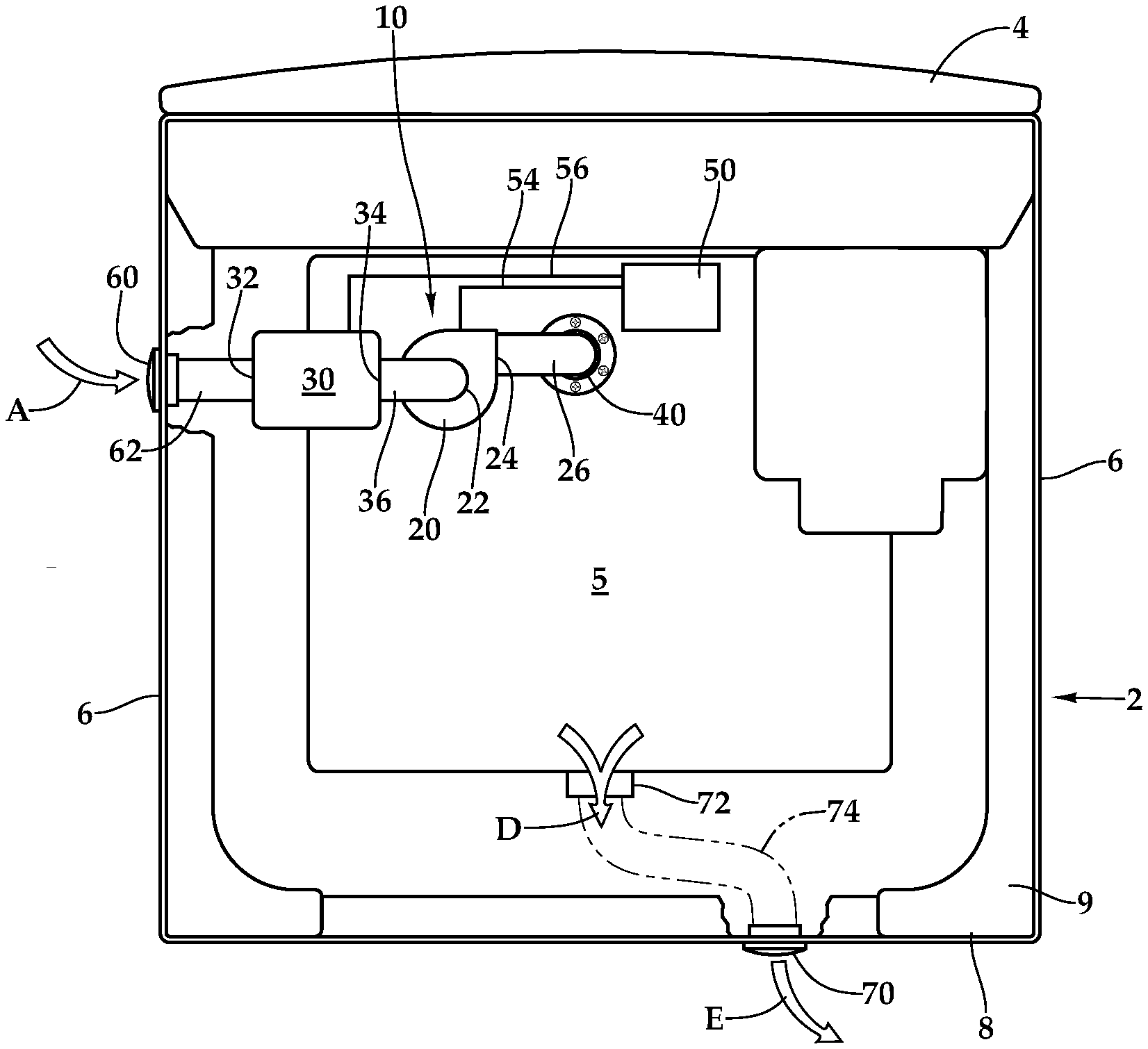
[0026] FIG. 1 is a top plan view of a washing machine including a ventilation system according to this invention, with a top of the washing machine cut away to reveal interior details.
[0027] FIG. 2 is a rear perspective view of that which is shown in FIG. 1.
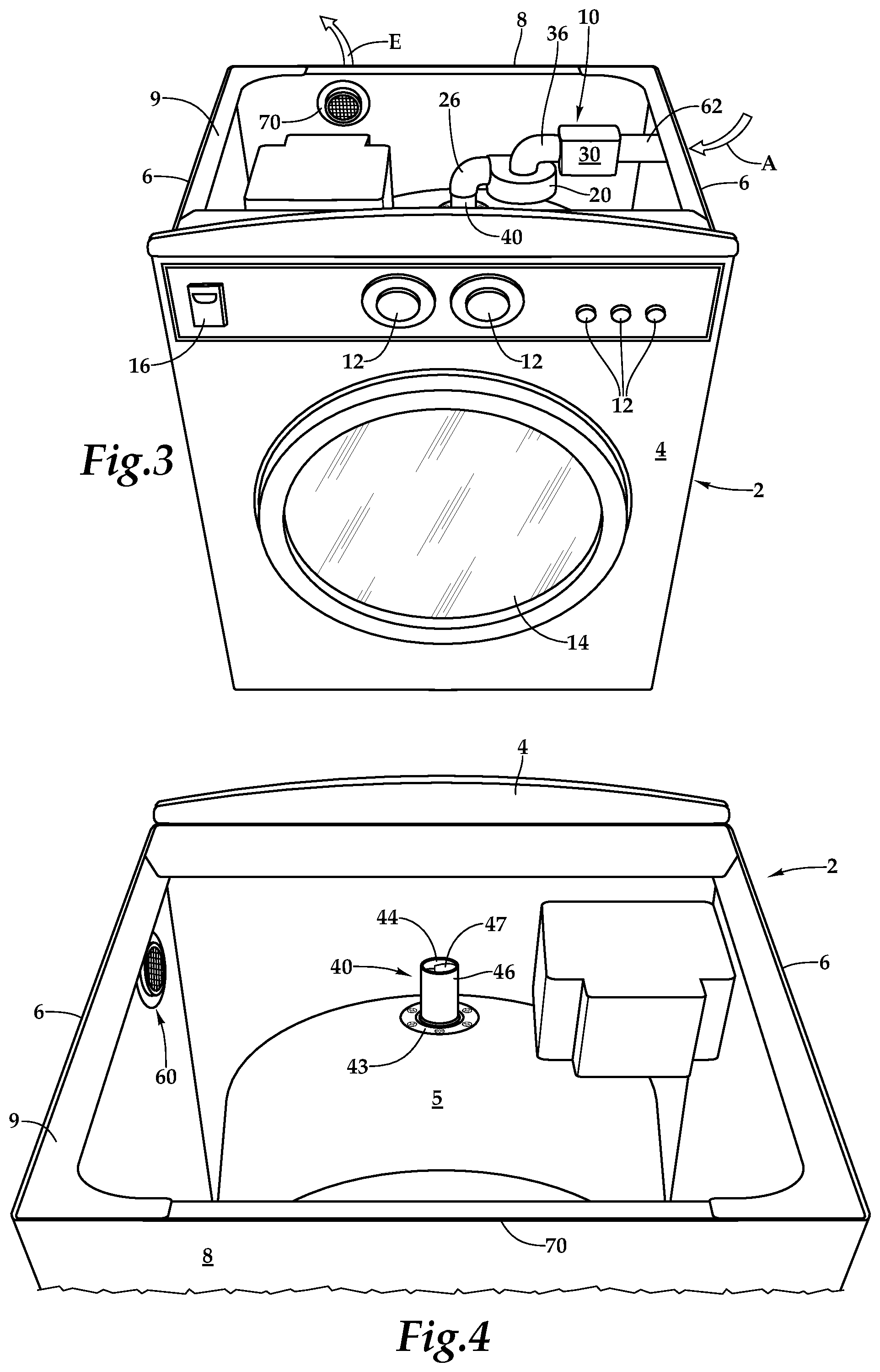
[0028] FIG. 3 is a front perspective view of that which is shown in FIG. 1.
[0029] FIG. 4 is a detail of a portion of that which is shown in FIG. 2, and with portions of the ventilation system removed, and showing one location for a water trap to keep water from exiting a water containing enclosure of the washing machine through an air inlet pathway of the ventilation system.
[0030] FIG. 5 is a front elevation full sectional view of a portion of a water containing enclosure and drum of the washing machine, and showing one embodiment of a water trap associated with a ventilation system according to this invention.
[0031] FIG. 6 is a full sectional detail similar to that which is shown in FIG. 5, but with sloping baffles within a water trap thereof.
[0032] FIG. 7 is a schematic front elevation view of a washing machine including the ventilation system of this invention for mold growth resistance.
[0033] FIG. 8 is a simplified front perspective view of a top loading bucket style washing machine fitted with a ventilation system according to an alternative embodiment of this invention.
[0034] FIG. 9 is a front perspective view similar to that which is shown in FIG. 8, but with the ventilation system driving moist air out of the washing machine rather than driving dry air into the washing machine.
[0035] FIG. 10 is a front elevation view of a front loading washing machine fitted with a ventilation system for blowing air into the washing machine.
[0036] FIG. 11 is a front elevation view similar to that which is shown in FIG. 10, but with a ventilation system configured to pull air out of the washing machine in this embodiment.
[0037] FIG. 12 is a table of humidity data versus time resulting from testing of a system provided according to one embodiment of this invention.
[0038] FIG. 13 is a graph of the data of FIG. 12, showing humidity versus time, while the system operates.
[0039] FIGS. 14-18 are graphs of both humidity and temperature versus time, utilizing a prototype provided according to this invention, and according to various different operating methodologies. The Y-axis represents units of humidity present or temperature in degrees Fahrenheit, while the X-axis represented elapsed time.
DESCRIPTION OF THE PREFERRED EMBODIMENT
[0040] Referring to the drawings, wherein like reference numerals represent like parts throughout the various drawing figures, reference numerals 10, 110 and 112 are directed to a ventilation system (FIGS. 1-3 and 7-11) for flow of air into and out of a water containing enclosure 5, 105 of a washer 2, 102 to prevent or discourage mold and/or mildew growth within the washer 2. Clothes and other laundry items L can thus remain for a longer period of time after a washing cycle with less concern for mold/mildew growth.
[0041] In essence, and with particular reference to FIGS. 1, 2 and 7, basic details of the ventilation system 10 are described, according to one illustrated embodiment. The ventilation system 10 includes a blower 20 shown in this embodiment interposed along an air inlet pathway leading from an entry 60 to the blower 20, before passing on to a water containing enclosure 5 of the washer 2. A heater 30 can optionally be provided along this air inlet pathway. The blower 20 can alternatively be provided on an air outlet pathway leaving out of the enclosure 5 of the washer 2 (FIG. 11). A water trap 40 is preferably provided near where the air inlet pathway passes into the enclosure 5 of the washer 2, to prevent water from escaping out of the enclosure 5 along the air inlet pathway. A controller 50 is preferably provided which controls operation of the blower 20 and optional heater 30, especially based on readings received from a humidity sensor 52 contained within the enclosure 5 (or along an air outlet pathway). In addition to the entry 60 which pulls air from the surrounding environment into the ventilation system 10, an exit 70 is also preferably provided for removal of humid air from the enclosure 5 of the washer 10.
[0042] More specifically, and with particular reference to FIGS. 1-7, particular details of a typical washer 2 are described, which washer 2 could be modified according to this invention, either as original equipment or through installation of an aftermarket retrofit kit to the washer 2. The washer 2 is generally a washer for laundry items, such as clothing, but could be conceivably a washer 2 for other items, and is generally a washer 2 which utilizes water as part of the washing process executed by the washer 2.
[0043] The washer 2 generally includes a front 4 opposite a rear 8, and with sides 6 extending between the front 4 and the rear 8 to define a cabinet for the washer 2. A top 9 defines an upper portion of the cabinet of the washer 2. A water enclosure 5 is contained within the cabinet of the washer 2. A drum 7 is located within the enclosure 5. The drum 7 is configured to rotate about a substantially horizontal axis, while contained within the enclosure 5.
[0044] This washer 2 is generally in the form of a front loading washer 2 having a drum 7 rotating about a substantially horizontal axis, and with an enclosure 5 which is closed on all sides except for a front side. An alternative top load washer 102 (FIGS. 8 and 9) could alternatively support the ventilation system 110, which is akin to the ventilation system 10 of the first disclosed embodiment contained herein. Such a top load washer 102 would have an enclosure 105 which is open on an upper portion thereof, and would include a bucket 107 within the enclosure 105, which bucket 107 is configured to rotate about a substantially vertical axis.
[0045] A motor of some sort, typically an electric motor, is coupled to the drum 7 (or bucket 107) to cause the drum 7 (or bucket 107) to rotate in a particular fashion according to the design of the washer 2 (or washer 102). The drum 7 (or bucket 107) typically includes a cylindrical side wall (and optionally also a planar end wall) which is fenestrated. Water containment is thus primarily provided by the water containing enclosure 5 (or 105) rather than water being contained by the drum 7 (or bucket 107). As an alternative, and especially with top loading washers 102, the bucket 107 and enclosure 105 could be consolidated together into a single common element.
[0046] Prior art washers 2, 102 generally includes some degree of venting associated therewith. For instance, top load washers 102 have an openable lid, but this lid is not sealed, so that some venting of space inside the bucket 105 to air surrounding the washer 102 can be facilitated through such a lid and out of an upper portion of the bucket 105. While not strictly necessary, front loading washers 2 typically include some form of exhaust port 72 (FIGS. 1 and 7) so that the enclosure 5 is typically not 100% airtight, at least some of the time when a door on the front 4 of the washer 2 is closed. Such existing venting systems of washers 2, 102 are utilized in certain embodiments of this invention as a portion of a ventilating pathway leading into the water containing enclosure 5, 105 of the washer 2, 102, or out of the water continued enclosure 5, 105, according to this invention. In some embodiments, the ventilation system 10 of this invention can provide, separate from the existing washer 2, 102, both an air inlet pathway and an air outlet pathway.
[0047] Other details of the washer 2 according to typical embodiments include controls 12, which are typically on the front 4 of the washer 2, as well as a door 14 on the front 4 of the washer 2 and a soap drawer 16 on the front 4 of the washer 2. The controls 12 allow an operator to select an operating mode for the washer 2, while the door 14 allows for placement of laundry into and out of the drum 7 through the door 14. A soap drawer 16 provides a location where laundry soap can be provided so that it can be delivered into the drum 7 at an appropriate time during a washing cycle.
[0048] The controls allow an operator to influence details of a washing cycle such as an amount of water to be inputted into the water containing enclosure 5, a number of relatively low speed drum 7 rotation (along arrow F of FIGS. 5 and 6) washing cycles, as well as a number of relatively high speed "spin" cycles characterized by high speed rotation of the drum 7, such as for de-watering of laundry items within the drum 7. Other details of the washing cycles, such as when to input soap, and a number of water refill, water drain, and drum 7 spinning cycles are selected based on criteria such as the type of laundry being cleaned and an amount of soil and other debris to be removed from the laundry.
[0049] Most preferably according to this invention, and as described below, a controller 50 is provided according to this invention which can be integrated into the controls 12 of the washer 2 to further allow an operator to control an amount of ventilation to be provided, and other control of ventilating characteristics according to this invention, such as whether or not to include heat with the ventilating system 10, what level of humidity to tolerate within the enclosure 5, how much time to allow to pass before and between ventilating cycles (or to allow continuous ventilating) optional speed of airflow associated with the ventilating system 10, and whether or not to include some degree of drum 7 rotation associated with the ventilating system 10 (and how often to repeat such drum rotating and how much rotation to provide (e.g. just one-half turn)).
[0050] As an alternative, the controller 50 could be separately controlled from the controls 12 of the washer 2 so that the ventilating system 10 can operate substantially independently of other portions of the washer 2, such as to facilitate retrofitting of the ventilating system 10 onto a variety of different washing machines, without requiring extensive interconnection and re-programming and customization of the ventilation system 10 to work with different washers 2 of different designs. Also, and as noted above, the ventilation system 10, 110, 112 as one option, can be integrated into the washer 2 as original equipment, or the ventilation system 10, 110, 112 can be provided as an aftermarket retrofit kit to add the ventilation system 10, 110, 112 to an existing washer 2.
[0051] With particular reference to FIGS. 1-3 and 7-11, details of the blower 20 and optional heater 30 are described, according to this disclosed embodiment. The blower 20 could be any form of air movement device. In one embodiment, such as that disclosed herein, the blower 20 is a centrifugal blower having an input 22 generally near a central axis of a rotating impeller inside of a housing, and with an output 24 radially spaced from this rotational axis. A conduit 26 leads away from the blower 20 and toward the enclosure 5 of the washer 2. The blower 20 could, in a simplest embodiment, merely have a single speed, and only be controlled by turning the blower 20 on or off. In other embodiments, the blower 20 could have a variable speed drive and operate at different rotational speeds responsive to a control signal received from the controller 60. The blower 20 could, as an alternative, be an axial fan or could conceivably have some other form of prime mover configuration, such as pistons or lobes for moving air.
[0052] The heater 30 is optional for many embodiments of this invention. In one embodiment, the heater 30 can be integrated into the blower 20, so that whenever the blower 20 is operated, a heating element providing the heater 30 would also be activated. As an alternative, the heater 30 could be a separate element associated with the ventilation system 10. The heater 30 could have a single heating setting, or could have various different heating settings with different amount of heat added into air passing through the heater 30, responsive to control signals received from the controller 60.
[0053] While the heater 60 is typically merely provided as some form of heating element so that air flowing past the heating element is caused to be increased in temperature, the heater 30 could rely more extensively on conduction or radiation heat transfer, rather than primarily convection heat transfer, in various embodiments.
[0054] The heater 30 could also be configured as a dehumidifier, which would generally include both a cooling portion and a heating portion and with water removal therefrom. Air leaving the heater 30 in such a dehumidifier configuration could either be a similar temperature, a lower temperature or a higher temperature than air input it into such a dehumidifying heater 30. The goal of the heater 30 is to reduce relative humidity out of the air. A simplest embodiment merely increases temperature so that the relative humidity is decreased due to the characteristic of air that it can hold more moisture when it is at a higher temperature.
[0055] In more complex embodiments, the heater 30 can increase an amount of moisture which the air can hold by decreasing an amount of moisture contained within the incoming air, such as through a dehumidification process. Such a dehumidification process would generally include cooling sufficient to cause condensation of water within the air, followed by some degree of reheating. The resulting dehumidification process leaves the air with a greater ability to scavenge moisture from within the washer 2, then air which has not been dehumidified, heated or otherwise conditioned to increase its moisture gathering character.
[0056] In one embodiment, the ventilation system 10 can be provided in different forms, some merely including the blower 20, while others include both the blower 20 and heater 30, and still others including a blower 20 and heater 30 in the form of a more complex dehumidifier. The blower 20 and heater 30 can be provided in a modular arrangement to allow for a retrofit kit only including a blower 20 and without a heater, to be simply modified to interpose a heater 30 into the air inlet pathway, should it later be desired to add such a heater 30 to the ventilation system 10. For instance, sizes of fittings along the air input pathway and places where fittings are located within the air input pathway can be strategically provided to allow for the ventilation system 10 to operate effectively without a heater 30, or with a heater 30 later added thereinto. Such fittings along the air inlet pathway can be configured for separate placement of the blower 20 and heater 30, or for replacement of a blower 20 with a combined blower 20 and heater 30 unit, as a single element added into the air inlet pathway.
[0057] With particular reference to FIGS. 8-11 it can be seen that the blower 20, 120 can be either along the air inlet pathway of the ventilation system 10, 110 or can be provided along the air outlet pathway of the ventilation system 10, 112. Thus, the blower 20 can be pressurizing the enclosure 5, 105 or drawing a vacuum on the enclosure 5, 105. With either placement, ventilating airflow is caused to occur through the enclosure 5, 105 for discouraging of mold/mildew formation and/or growth. In contrast, if a heater 30 is provided, the heater 30 would always be on the air inlet pathway, so the benefits of air heating and/or dehumidification would be provided before air enters the enclosure 5, 105. Also, and in particular with regard to top load washer 102 embodiments, this entry line 114 or exit line 116 is preferably configured with the pathway including the blower 120 including a top bend 115 which extends above a water line W of the enclosure 105. This way, when the enclosure 105 is filled with water up to this waterline W, it does not cause water to escape out of the air inlet pathway or outlet pathway associated with the blower 120.
[0058] With particular reference to FIGS. 5 and 6, details of a water trap 40 are described, according to two similar embodiments. The water trap 40 is provided to prevent water from escaping from the water containing enclosure 5 through the air inlet pathway (or outlet pathway for vacuum based systems (FIG. 11)). The water trap 40 in this embodiment includes an air port 42 surrounded by a flange 43 where the water trap 40 interfaces with the enclosure 5 of the washer 2. A top port 44 is located above the air port 42. Sidewalls 46 surround the water trap 40 between the air port 42 at a bottom of the water trap 40 and the top port 44 at a top of the water trap 40. This water trap 40 is preferably provided at an uppermost portion of the enclosure 5, so that the sidewalls 46 extend substantially vertically from the air port 42 to the top port 44. As an alternative, the water trap 40 could function effectively on a portion of the enclosure 50 lower than an upper most portion of the enclosure 5, and generally anywhere on an upper half of the enclosure 5.
[0059] When water splashes up against the water trap 40 from within the enclosure 5, such as during washing cycles of the washer 2, or when encountering a spin cycle (with rapid spinning of the drum 7 along arrow F) water is kept from exiting through the water trap 40 by placement of baffles 48 therein. Any water attempting to extend up through the water trap 40 encounters the baffles 48 and cannot make it out of the top port 44 at an upper end of the water trap 40. Such water impacting the baffles 48 then eventually drips back down into the enclosure 5.
[0060] In the water trap 40 embodiment of FIG. 6, tapered baffles 47 are provided which extend from opposing sidewalls 46 to lower free edges 49. The tapered baffles 47 alternate in their height position, extending from opposing side walls as the baffles 47 are sequentially placed between the air port 42 at the bottom of the water trap 40 and the top port 44 at the top of the water trap 40. With the tapered baffles 47, any water coming into contact with the baffles 47 runs down to the lower free edges 49 for collection of the water and dripping back down into the enclosure 5. Other forms of water traps 40 could alternatively be provided.
[0061] With particular reference to FIGS. 1, 2 and 7, details of the controller 50 are described, according to one embodiment. The controller 50 can be a separate device from the controls 12 of the washer 2, or can be integrated into the controls 12 of the washer 2. The controller 50 general includes a processor and a power supply, and various inputs and outputs so the controller 50 can execute a program (such as residing in a memory device) for desired operation of the ventilation system 10 according to various embodiment of this invention.
[0062] The controller 50 preferably includes the humidity sensor 52 as one input into the controller 50. The controller 50 preferably includes at least one output in the form of a blower control line 54 extending from the controller 50 to the blower 20. The blower control line 54 delivers a signal to the blower 20 to cause blower 20 operation, and potentially also a speed of operation of the blower 20. An optional heater control line 56 extends from the controller 50 to the heater 30 and provides for operation of the heater 30, and optionally different heat settings for the heater 30.
[0063] Other outputs from the controller 50 could include outputs interfacing with the controls 12 of the washer 2 or directly with a motor driving the drum 7, so that the controller 50 can cause some rotation of the drum 7, such as to "fluff" clothes or other laundry contained within the drum 7 and to further discourage pockets of moisture adjacent to the laundry which might otherwise be ideal for mold/mildew growth.
[0064] Still other inputs and outputs for the controller 50 could include status lights, door position sensors, such as which might shut off the ventilation system 10 after a door 14 of the washer 2 is opened (unless an operator input is received to keep the ventilation system 10 operational). A timer input can be used by the controller 50 to cause the ventilation system 10 to run for selected amounts of time and/or on/off intervals, such as five minutes of operation every hour until the door is opened. Wireless inputs and outputs can be provided for remote operation and optionally for display of humidity information on a smartphone or remote computer, and for adjusting of set points, such as adjusting an acceptable level of humidity to be maintained within the drum 7.
[0065] In use and operation, and with particular reference to FIGS. 1-11, details of the operation of the ventilation system 10, 110, 112 are described for provision of air into a washer 2, 102 to prevent or discourage mold/mildew growth within the washer 2, 102. Initially, air enters the ventilation system 10 through an entry 60 (FIG. 8) and along a conduit 62 leading to at least a blower 20, 120 (or a heater 30 upstream of the blower 20). In a vacuum option 112 (FIG. 9) the entry 60 merely includes a conduit 62 leading into the drum 7 or bucket 107. The blower 20 provides motive force to move the air, along arrow A, through the entry 60, along the conduit 62, and into the enclosure 5, 105.
[0066] This air passes through a water trap 40 in a preferred embodiment, first entering the water trap 40 along arrow B, and then passing into the enclosure 5 along arrow B, and typically through fenestrations in the drum 7 (or bucket 107) to come into contact with clothes or other laundry items L (FIG. 7) within the drum 7 (or bucket 107).
[0067] If any water splashes up into the water trap 40, such as during operation of the washer 2 (e.g. when the drum 7 is spinning quickly (along arrow F) and dewatering laundry items in a way which throws water upward against the enclosure 5, and into the water trap 40), the water is stopped. The water then collects on the baffles 47, 48 and drops back down into the enclosure 5 (along arrow C of FIGS. 5 and 6).
[0068] The air input into the drum 7 (or bucket 107) comes into contact with humid air pockets and wet laundry within the drum 7 (or bucket 107) and the air is humidified as this water within the drum 7 (or bucket 107) evaporates. The humidified air is then discharged out of the enclosure 5, 105, such as along exhaust ports 72 in a rear wall of the drum 7, opposite the door 14 of the washer 2, or merely discharges along arrow D out of an upper portion of the bucket 107 and enclosure 105 beneath a lid and a top of a top load washer 102 (FIGS. 8 and 9). This humid air is then routed out through an exit 70 (along arrow E). This exit 70 can be located in the rear 8 of the washer 2. In one embodiment, passage of humid air through the exit 70 (along arrow E) is provided along a conduit 74 extending from exhaust port 72 to the exit 70 (FIG. 1). As an alternative, the exhaust port 72 can merely lead out of the enclosure 5, and humid air will eventually find its way out of the outer cabinet, through the exit 70 in the rear 8 (or side 6) or out through a floor or otherwise leak out of an outer cabinet of the washer 2.
[0069] In embodiments where the blower 20 is downstream of the enclosure 5, 105 (FIGS. 9 and 11) air enters through the entry 60 along the conduit 62 (along arrow A), or merely flows directly into an upper portion of the bucket 107 of a top load washer 102. Downstream of the conduit 62, the air passes into the enclosure 5 where it comes into contact with the wet laundry and is humidified. The humid air is then discharged from the enclosure 5, a long arrow D, and then is routed into the blower 20, before discharge at an exit along arrow E.
[0070] FIGS. 12-18 display data associated with testing conducted with various prototypes constructed according to this invention. A first prototype used a very basic hairdryer as both the blower 20 and heater 30. A front loading washer 2 was modified to provide a flexible hose extending from the blower 20 and heater 30 into the enclosure 5 of the washer 2. Existing enclosure 5 venting was allowed to provide a humid air outlet pathway into a cabinet of the washer 2, and an exit 70 was provided in the rear 8 of the washer 2 for final discharge of the humid air.
[0071] In a test of this first prototype, a humidity sensor and a clock were used. Humidity within the enclosure 5 began at 74% relative humidity. The blower 20 and heater 30 combination in the form of the hairdryer was turned on and humidity readings were taken in five minute intervals. Graphing of this data resulting from testing of this first prototype is shown in FIGS. 12 and 13. Basic efficacy of the ventilation system 10 according to this first prototype was thus established. In some instances 60% relative humidity is acceptable, while in other embodiments 50% relative humidity is a goal. Two set points can be spaced apart to avoid excess on/off cycling of the system 10.
[0072] A second prototype was constructed utilizing a small blower rated at 16 ft..sup.3 per minute, with a rated voltage of 6-12 VDC and a rated current of 0.9 A, and a rated power of 10 W. Fan speed of 3000 to 3500 RPM was provided by this blower 20. A humidity control sensor and a controller 50 in the form of a basic timer were also included and wired between the blower 20 and a power supply. Higher quality timers were utilized in various different tests. Particular details of five tests of this second prototype are set forth below, with graphing of data obtained shown in FIGS. 14-18.
[0073] Graph 1 (FIG. 14)
[0074] Items: Washer, ventilation system, humidity and temperature sensor.
[0075] Trigger: Ventilator is manually started by hand.
[0076] Purpose: To validate that the new direct current ventilator is capable of reducing the humidity inside the washer drum. Steps:
[0077] 1. Spray water into the inside of the empty washer drum at the start of the experiment.
[0078] 2. Wait for the humidity level to go up.
[0079] 3. Manually start the ventilator when the humidity level is high enough.
[0080] Data Analysis:
[0081] 1. The temperature goes down with increasing humidity level indicating energy is used during evaporation of water.
[0082] 2. The temperature continues to drop when the ventilation system is turned on. This is probably because remaining water is still evaporating. Later, the temperature started to increase, probably because most of the water had been evaporated and the incoming air is warmer.
[0083] 3. The humidity level started to go down at the start of the ventilation system and went below 60% within about 30 minutes. This indicates that the small ventilator capacity is good enough to ventilate the washer drum.
[0084] Graph 2 (FIG. 15)
[0085] Items: Washer, ventilation system, humidity and temperature sensor, analog timer.
[0086] Trigger: Ventilator is automatically started by an analog timer.
[0087] Purpose: To see the humidity level with the ventilation system settings at a 30 minutes on and 30 minutes off intervals. Steps:
[0088] 1. Add dripping wet bath towels (should be damp towels in hindsight).
[0089] 2. Spray water into the inside of the washer drum at start of experiment.
[0090] 3. The ventilator is set to start 30 minutes into the experiment with 30 minutes on/off intervals.
[0091] Data Analysis:
[0092] 1. The temperature goes down as evaporation takes up energy from the area inside the drum. The temperature dropped faster when ventilation system is operating, as a result of increased evaporation.
[0093] 2. The humidity level rose in idle air as expected at the start of the experiment.
[0094] 3. The temperature continued to go down when the ventilation system is operating because of increased evaporation.
[0095] 4. In the first ventilation interval, increased evaporation is trying to keep the humidity level up indicated by the slower drop of humidity level (when compared to the second ventilation interval).
[0096] 5. The second idle air interval is less than 30 minutes because of the imprecise analog timer (this analog timer is replaced with a digital timer for subsequent experiment).
[0097] 6. In the second ventilation interval, the humidity level drops faster than the first interval. At this time, it was visually observed that most of the water sprayed on the drum is already evaporated. New moisture feeding the humidity level is mostly coming from the wet towels.
[0098] 7. The third idle air period is long because the experiment was stopped. But data recording continues to see the impact of wet towels on the humidity level. The wet towels are keeping the humidity level high.
[0099] Graph 3 (FIG. 16)
[0100] Items: Washer, ventilation system, humidity and temperature sensor, digital timer.
[0101] Trigger: Ventilator system is automatically started by a digital timer.
[0102] Purpose: To see the humidity level with active air at 30 minutes on and 30 minutes off intervals (no dripping wet towels). Steps:
[0103] 1. Spray water into the inside of the washer drum at the start of the experiment.
[0104] 2. Drum is empty (i.e. no dripping wet towels).
[0105] 3. Purposely let the humidity level build up.
[0106] 4. Ventilator is initially started manually but subsequent on/off is automatic at a with 30 minutes on/off intervals.
[0107] Data Analysis:
[0108] 1. The temperature goes down as evaporation takes up energy from the area inside the drum. The temperature drops faster when ventilation system is operating, as a result of increased evaporation.
[0109] 2. By now and from previous experiments, it is apparent that in the first ventilation interval, the drum is continuing to dry and in the second ventilation interval, the drum is almost dried, indicated by the faster drop in the humidity level.
[0110] 3. It looks like an hour is about the right time to fully dry the drum, as the humidity seemed to flatten out in a third idle air interval. The experiment is stopped in the third idle air interval but with continuing data collection. In hindsight, we should have continued to a third ventilation interval.
[0111] Graph 4 (FIG. 17)
[0112] Items: Washer, ventilation system, humidity and temperature sensor, humidity controller.
[0113] Trigger: Ventilator system is automatically is started by humidity controller (with the on/off levels pre-programmed).
[0114] Purpose: To see the humidity level with the ventilation system controlled by a pre-programmed humidity controller. Steps:
[0115] 1. The humidity controller is programmed to turn on the air blower at 60% humidity level and turn off at 55% humidity.
[0116] 2. Spray water into the inside of the washer drum at start of experiment (i.e. no wet towels).
[0117] Data Analysis:
[0118] 1. The temperature goes down as evaporation takes up energy from the area inside the drum. The temperatures drop down faster when ventilation system is operating, as a result of increased evaporation.
[0119] 2. The humidity rises quickly and hit the trigger point of the humidity controller. This activated the ventilation system quickly. It is interesting to note that the humidity level is continuing to rise for a minute or two because of the high level of evaporation taking place at the beginning of the experiment.
[0120] 3. The activated ventilation system interval is long as high evaporation rate is keeping the humidity level up. Towards the middle of the ventilation interval, you can see evaporation is starting to slow down indicated by the dropping of the humidity level eventually hitting the off trigger point at 55% humidity level.
[0121] 4. It is interesting to point out that the humidity level continued to drop a bit in the second idle air interval, perhaps because temperature rose a bit (i.e. warmer air holds more moisture).
[0122] 5. It is also interesting to point out that the drum dries out much faster indicating it may be efficient to start the ventilation system early, at a 60% humidity level. This experiment needs to be repeated to reconfirm the result.
[0123] Graph 5 (FIG. 18)
[0124] Items: Washer, ventilation system, humidity and temperature sensor, humidity controller, digital timer.
[0125] Trigger: Ventilator system is automatically started by the humidity controller (on/off levels) gated by a timer.
[0126] Purpose: To see the impact of adding a gating timer on the pre-programmed humidity controller to on/off humidity levels. Steps:
[0127] 1. The humidity controller is programmed to turn on the air blower at 60% and turn off at 55%.
[0128] 2. The digital timer is set at 30 minutes on/off intervals, with the timer set to on at the start of the experiment.
[0129] 3. Spray water into the inside of the washer drum at the start of the experiment (i.e. no wet towels).
[0130] Data Analysis:
[0131] 1. The temperature goes down as evaporation takes up energy from the area inside the drum. The temperature drops down faster when the ventilation system is operating, as a result of increased evaporation.
[0132] 2. The humidity rises quickly and hit the trigger point of the humidity controller. This activated the ventilation system quickly. It is interesting to note that the humidity level is continuing to rise for a minute or two because of the high level of evaporation taking place at the beginning of the experiment.
[0133] 3. Note the very similar humidity trend to Graph 4 (FIG. 17) at the beginning up until when the digital timer turns off the ventilation system.
[0134] 4. The humidity level started to climb again at the second idle air interval until the digital timer turns on again.
[0135] 5. When the ventilation system turns on again, the humidity level drops steeply to below 55% and thus triggering the humidity controller to turn off again. This steep drop indicates the drum is almost dry.
[0136] 6. A slow humidity level climb in third idle air interval indicating the drum is almost dry.
[0137] 7. The last active air interval is actually a manual override to observe the humidity level behavior in an almost dry washer drum.
[0138] This disclosure is provided to reveal a preferred embodiment of the invention and a best mode for practicing the invention. Having thus described the invention in this way, it should be apparent that various different modifications can be made to the preferred embodiment without departing from the scope and spirit of this invention disclosure. When embodiments are referred to as "exemplary" or "preferred" this term is meant to indicate one example of the invention, and does not exclude other possible embodiments. When structures are identified as a means to perform a function, the identification is intended to include all structures which can perform the function specified. When structures of this invention are identified as being coupled together, such language should be interpreted broadly to include the structures being coupled directly together or coupled together through intervening structures. Such coupling could be permanent or temporary and either in a rigid fashion or in a fashion which allows pivoting, sliding or other relative motion while still providing some form of attachment, unless specifically restricted.
* * * * *
D00000
D00001
D00002
D00003
D00004
D00005
D00006
D00007
XML
uspto.report is an independent third-party trademark research tool that is not affiliated, endorsed, or sponsored by the United States Patent and Trademark Office (USPTO) or any other governmental organization. The information provided by uspto.report is based on publicly available data at the time of writing and is intended for informational purposes only.
While we strive to provide accurate and up-to-date information, we do not guarantee the accuracy, completeness, reliability, or suitability of the information displayed on this site. The use of this site is at your own risk. Any reliance you place on such information is therefore strictly at your own risk.
All official trademark data, including owner information, should be verified by visiting the official USPTO website at www.uspto.gov. This site is not intended to replace professional legal advice and should not be used as a substitute for consulting with a legal professional who is knowledgeable about trademark law.