Mid-sprocket Assembly
CHOLTCO-DEVLIN; Evan Michael
U.S. patent application number 16/706042 was filed with the patent office on 2020-06-04 for mid-sprocket assembly. This patent application is currently assigned to Fox Factory, Inc.. The applicant listed for this patent is Fox Factory, Inc.. Invention is credited to Evan Michael CHOLTCO-DEVLIN.
| Application Number | 20200172198 16/706042 |
| Document ID | / |
| Family ID | 68766753 |
| Filed Date | 2020-06-04 |


| United States Patent Application | 20200172198 |
| Kind Code | A1 |
| CHOLTCO-DEVLIN; Evan Michael | June 4, 2020 |
MID-SPROCKET ASSEMBLY
Abstract
A mid-sprocket assembly is disclosed herein. The mid-sprocket assembly includes an input shaft to receive an input force, the input shaft having a plurality of input shaft gears coupled therewith. A countershaft having a plurality of countershaft gears coupled therewith, at least one of the plurality of countershaft gears selectively and axially engaged to receive the input force from at least one input shaft gears and provide the input force to a rear wheel to drive the rear wheel.
| Inventors: | CHOLTCO-DEVLIN; Evan Michael; (North Vancouver, CA) | ||||||||||
| Applicant: |
|
||||||||||
|---|---|---|---|---|---|---|---|---|---|---|---|
| Assignee: | Fox Factory, Inc. Braselton GA |
||||||||||
| Family ID: | 68766753 | ||||||||||
| Appl. No.: | 16/706042 | ||||||||||
| Filed: | December 6, 2019 |
Related U.S. Patent Documents
| Application Number | Filing Date | Patent Number | ||
|---|---|---|---|---|
| 62773983 | Nov 30, 2018 | |||
| Current U.S. Class: | 1/1 |
| Current CPC Class: | B62M 9/06 20130101; B62M 1/36 20130101; B62M 11/06 20130101; A61F 2/1637 20130101; A61B 3/0025 20130101; G16H 50/50 20180101 |
| International Class: | B62M 11/06 20060101 B62M011/06; B62M 9/06 20060101 B62M009/06 |
Claims
1. A mid-sprocket assembly comprising: an input shaft to receive an input force, the input shaft having a plurality of input shaft gears coupled therewith; and a countershaft having a plurality of countershaft gears coupled therewith, at least one of the plurality of countershaft gears selectively and axially engaged to receive the input force from at least one of the plurality of input shaft gears and provide an output force to a drive wheel of a vehicle.
2. The mid-sprocket assembly of claim 1, wherein the drive wheel of the vehicle is a rear wheel of the vehicle.
3. The mid-sprocket assembly of claim 1, further comprising: an output shaft to receive the output force from at least one of the plurality of countershaft gears; a chainring coupled with the output shaft; and a chain rotatably coupled with the chainring, the chain to transfer the output force from the chainring to the drive wheel of the vehicle.
4. The mid-sprocket assembly of claim 1, further comprising: an output shaft to receive the output force from at least one of the plurality of countershaft gears; a belt cog coupled with the output shaft; and a belt rotatably coupled with the belt cog, the belt to transfer the output force from the belt cog to the drive wheel of the vehicle.
5. The mid-sprocket assembly of claim 1, further comprising: a shifting mechanism, the shifting mechanism comprising: a shifting shaft within the mid-sprocket assembly, the shifting shaft coupleable with at least one of the plurality of countershaft gears on the countershaft; and a shifter located away from said mid-sprocket assembly, the shifter communicatively coupled with the shifting shaft, a manipulation of the shifter causes the shifting shaft to select one of said at least one of said plurality of countershaft gears to engage with said at least one of the plurality of input shaft gears.
6. The mid-sprocket assembly of claim 5, wherein said shifting shaft further comprises: a plurality of shift rings coupled therewith, the plurality of shift rings interspersed within said plurality of countershaft gears, the plurality of shift rings having varying spaces and space angles, each of the plurality of shift rings comprising: a shift ring cam pin hole, the shift ring cam pin hole to receive a cam pin, the cam pin to couple at least one of the plurality of shift rings with the input shaft via an input shaft cam pin hole on said input shaft.
7. The mid-sprocket assembly of claim 6, further comprising: each of the plurality of countershaft gears having a countershaft pawl interface on one side thereof; and each of the plurality of shift rings further comprising: a shift pawl interface on at least one side thereof, said shift pawl interface of at least one of said plurality of shift rings engages with said countershaft pawl interface of one countershaft gear to engage said countershaft with said input shaft.
8. A method of transmitting a force received from a drive component to a drive wheel of a vehicle via a mid-sprocket assembly, the method comprising: receiving an input force from a drive component to at least one input shaft gear of an input shaft, the input shaft having a plurality of input shaft gears coupled therewith; transferring the input force from the input shaft to at least one countershaft gear of a countershaft, the countershaft having a plurality of countershaft gears coupled therewith; generating an output force from the countershaft, the output force generated from the input force transferred from the input shaft; and providing the output force to a drive wheel of a vehicle.
9. The method of claim 8 wherein transferring the input force further comprises: selectively and axially engaging at least one of the plurality of countershaft gears with at least one of the plurality of input shaft gears; and transferring the input force to one of the plurality of countershaft gears from one of the plurality of input shaft gears.
10. The method of claim 8, wherein the drive wheel of the vehicle is a rear wheel of the vehicle.
11. The method of claim 8, further comprising providing the output force from the countershaft to an output shaft; coupling a chainring with the output shaft; providing a chain to couple the chainring with the drive wheel; and utilizing the chain to transfer the output force from the chainring to the drive wheel of the vehicle.
12. The method of claim 8, further comprising providing the output force from the countershaft to an output shaft; coupling a belt cog with the output shaft; providing a belt to couple the belt cog with the drive wheel; and utilizing the belt to transfer the output force from the belt cog to the drive wheel of the vehicle.
13. The method of claim 8, further comprising providing a shifting shaft within the mid-sprocket assembly; and communicatively coupling a shifter with the shifting shaft, the shifter located away from said mid-sprocket assembly; and manipulating the shifter causes the shifting shaft to engage with said input shaft and said countershaft.
14. The method of claim 13, further comprising: providing an input shaft cam pin hole on said input shaft; providing a countershaft pawl interface on one side of each of the plurality of countershaft gears; and coupling a plurality of shift rings with the shifting shaft, the plurality of shift rings interspersed within said plurality of countershaft gears, the plurality of shift rings having varying spaces and space angles, each of the plurality of shift rings comprising: a shift ring cam pin hole, utilizing a cam pin to couple at least one of the plurality of shift rings with said input shaft; each of the plurality of shift rings further comprising: a shift pawl interface on at least one side thereof; and utilizing said shift pawl interface to engage with said countershaft pawl interface thereby coupling at least one of the plurality of shift rings with at least one of said plurality of countershaft gears.
15. A mid-sprocket assembly comprising: an input shaft to receive an input force, the input shaft having a plurality of input shaft gears coupled therewith; and a countershaft having a plurality of countershaft gears coupled therewith, at least one of the plurality of countershaft gears selectively and axially engaged to receive the input force from at least one of the plurality of input shaft gears and provide an output force; and an output shaft to receive the output force from at least one of the plurality of countershaft gears, and transfer the output force to a drive wheel of a vehicle.
16. The mid-sprocket assembly of claim 15, further comprising: a chainring coupled with the output shaft; and a chain rotatably coupled with the chainring, the chain to transfer the output force from the chainring to the drive wheel of the vehicle.
17. The mid-sprocket assembly of claim 15, further comprising: a belt cog coupled with the output shaft; and a belt rotatably coupled with the belt cog, the belt to transfer the output force from the belt cog to the drive wheel of the vehicle.
18. The mid-sprocket assembly of claim 15, further comprising: a shifting shaft within the mid-sprocket assembly; and a shifter located away from said mid-sprocket assembly, the shifter communicatively coupled with the shifting shaft, a manipulation of the shifter causes the shifting shaft to engage with one of said plurality of countershaft gears.
19. The mid-sprocket assembly of claim 18, wherein said shifting shaft further comprises: a plurality of shift rings coupled therewith, the plurality of shift rings interspersed within said plurality of countershaft gears, the plurality of shift rings having varying spaces and space angles, each of the plurality of shift rings comprising: a shift ring cam pin hole, the shift ring cam pin hole to receive a cam pin, the cam pin to couple at least one of the plurality of shift rings with the input shaft via an input shaft cam pin hole on said input shaft.
20. The mid-sprocket assembly of claim 19, further comprising: each of the plurality of countershaft gears having a countershaft pawl interface on one side thereof; and each of the plurality of shift rings further comprising: a shift pawl interface on at least one side thereof, said shift pawl interface of at least one of said plurality of shift rings engages with said countershaft pawl interface of one countershaft gear to engage said countershaft with said input shaft.
Description
CROSS-REFERENCE TO RELATED APPLICATIONS (PROVISIONAL)
[0001] This application claims priority to and benefit of co-pending U.S. Provisional Patent Application No. 62/773,983 filed on Dec. 7, 2018, entitled "MID-SPROCKET ASSEMBLY" by Evan Michael Choltco-Devlin, and assigned to the assignee of the present application, the disclosure of which is hereby incorporated by reference in its entirety.
FIELD OF THE INVENTION
[0002] Embodiments of the invention generally relate to a mid-sprocket assembly for a bicycle.
BACKGROUND
[0003] In a bicycle, such as a mountain bike (or the like) that has a number of gears in a cassette in the rear and a chainring in the middle, there can be a significant amount of vibration, suspension flex, cross-chaining, and other detrimental actions that can cause roller chain disengagement. For example, as the roller chain moves to the peripheral gears on the rear cassette, there is an increase in the lateral angle at which the roller chain approaches the chainring. These different approach angles can deleteriously affect the ability of the traditional chainring to retain the roller chain thereby resulting in roller chain disengagement.
BRIEF DESCRIPTION OF THE DRAWINGS
[0004] Aspects of the present invention are illustrated by way of example, and not by way of limitation, in the accompanying drawings, wherein:
[0005] FIG. 1 is an orthogonal view of a mid-sprocket assembly, in accordance with an embodiment.
[0006] FIG. 2 is a sectional view of the mid-sprocket assembly, in accordance with an embodiment.
[0007] FIG. 3 is a sectional view of the gear engagement/disengagement of the mid-sprocket assembly, in accordance with an embodiment.
[0008] FIG. 4 is a side view of the shifting shaft including the camming slot features, in accordance with an embodiment.
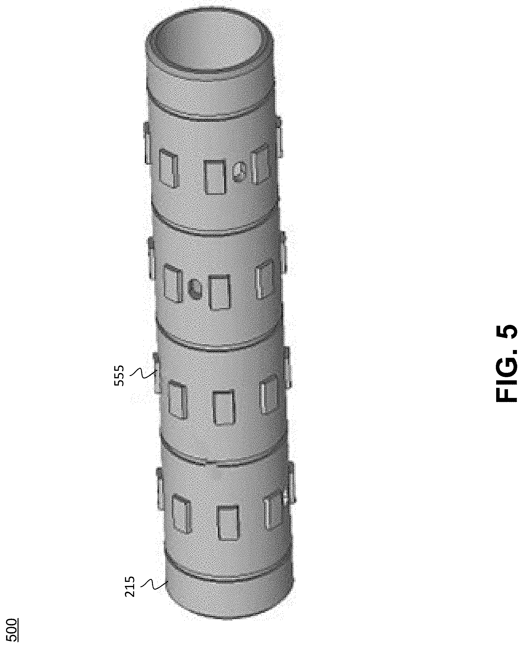
[0009] FIG. 5 is an orthogonal view of the countershaft that includes the teeth for engaging with the interior splines of a shift ring, in accordance with an embodiment.
[0010] FIG. 6A is an orthogonal view of a shift ring with pawls and a cam pin hole, in accordance with an embodiment.
[0011] FIG. 6B is a side view of the shift ring with side teeth/pawls for engagement with the gear ring and inner circumference splines for engagement with the countershaft, in accordance with an embodiment.
[0012] The drawings referred to in this description should be understood as not being drawn to scale except if specifically noted.
DESCRIPTION OF EMBODIMENTS
[0013] The detailed description set forth below in connection with the appended drawings is intended as a description of various embodiments of the present invention and is not intended to represent the only embodiments in which the present invention is to be practiced. Each embodiment described in this disclosure is provided merely as an example or illustration of the present invention, and should not necessarily be construed as preferred or advantageous over other embodiments. In some instances, well known methods, procedures, and objects have not been described in detail as not to unnecessarily obscure aspects of the present disclosure.
[0014] The disclosed mid-sprocket assembly also increases chain retention capabilities by removing the alignment relationship between the sprocket and the rear drive gear as the different gears are no longer on the rear cassette, but are instead part of the mid-sprocket assembly.
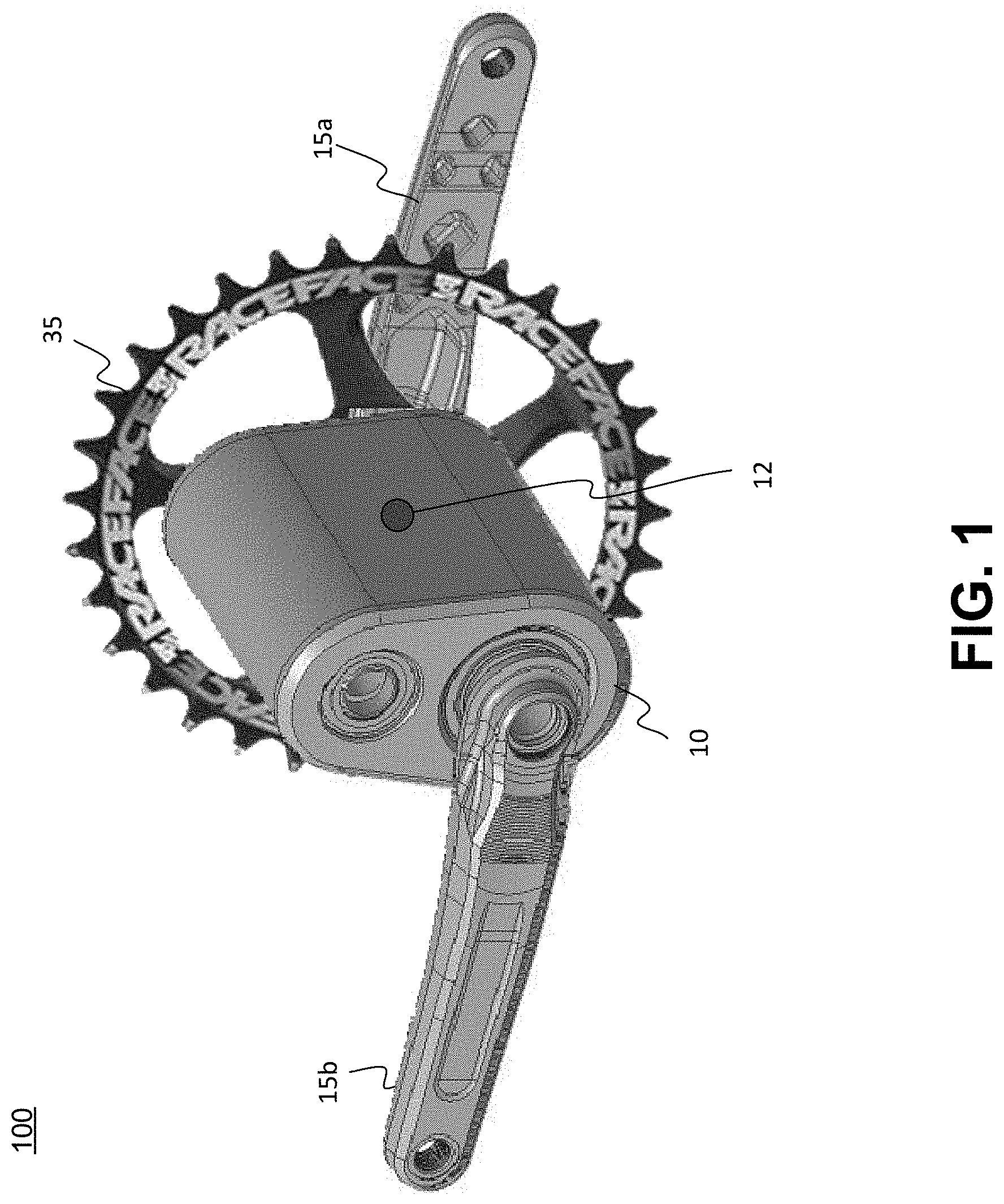
[0015] Referring now to FIG. 1, an orthogonal view 100 of a mid-sprocket assembly 10 is shown in accordance with an embodiment. Mid-sprocket assembly 10 is shown in conjunction with a left-hand non-drive crank arm 15b, a right-hand drive side crank arm 15a, and a chainring 35. In general, mid-sprocket assembly 10 is mounted into some number of modular interfaces in a bicycle frame and does both the power transmission and the gear shifting actions that is normally split up into a crankset at the front end and a derailleur at the rear wheel including a derailleur cassette cog cluster and chain.
[0016] Although a chainring 35 is shown, it is merely one of a plurality of ways for the mid sprocket assembly 10 to provide drive to the rear wheel. In one embodiment, instead of a chainring, there could be a belt cog, a chain cog, or the like to provide final drive to the rear wheel. Mid-sprocket assembly 10 also includes a shifting mechanism 12 at the center panel of the mid-sprocket assembly 10 that allows the shifting from a shifter (or shifters) at the handlebars (or other location) that is manipulated by the rider to shift the internal gears within the mid-sprocket assembly 10.
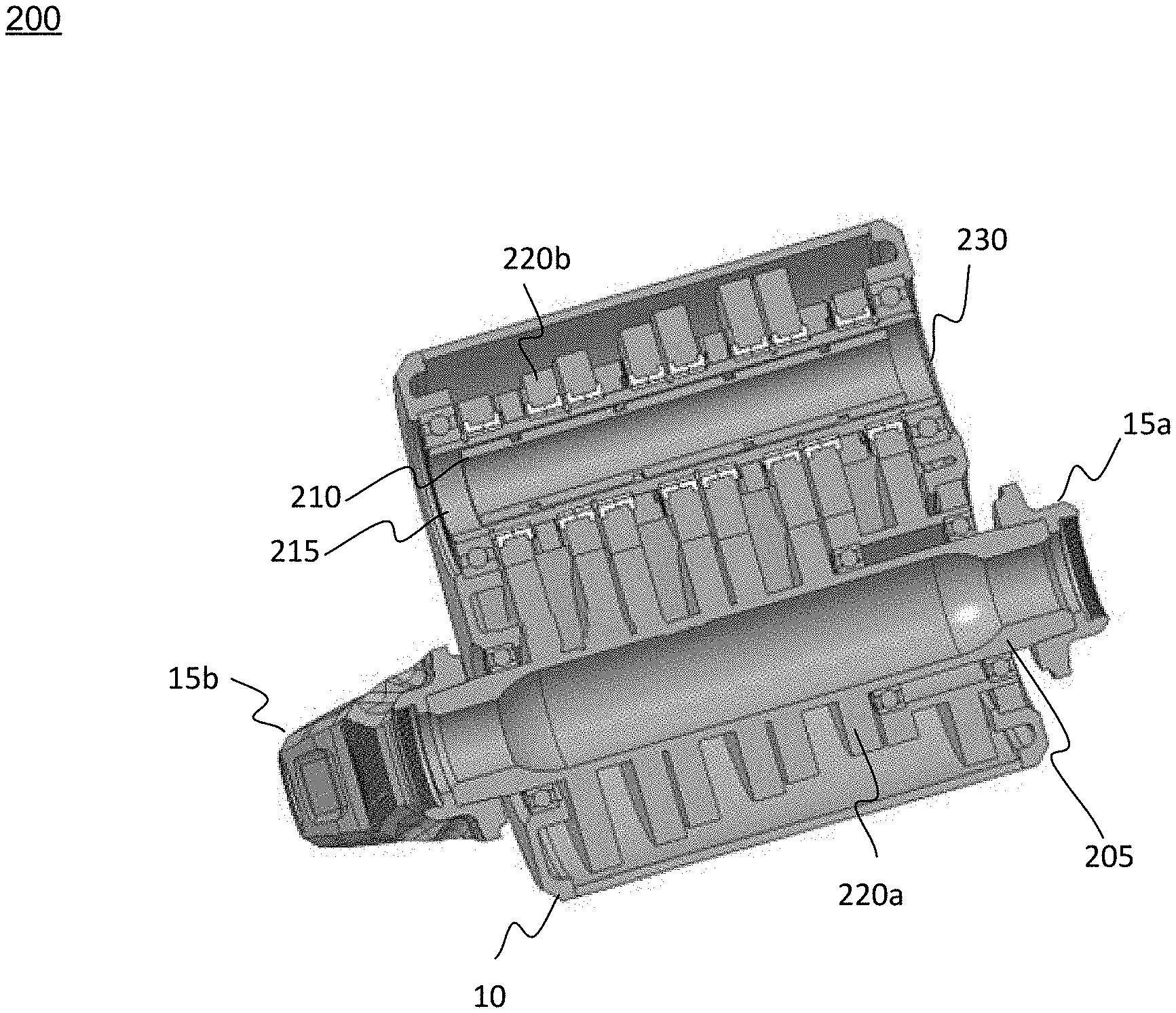
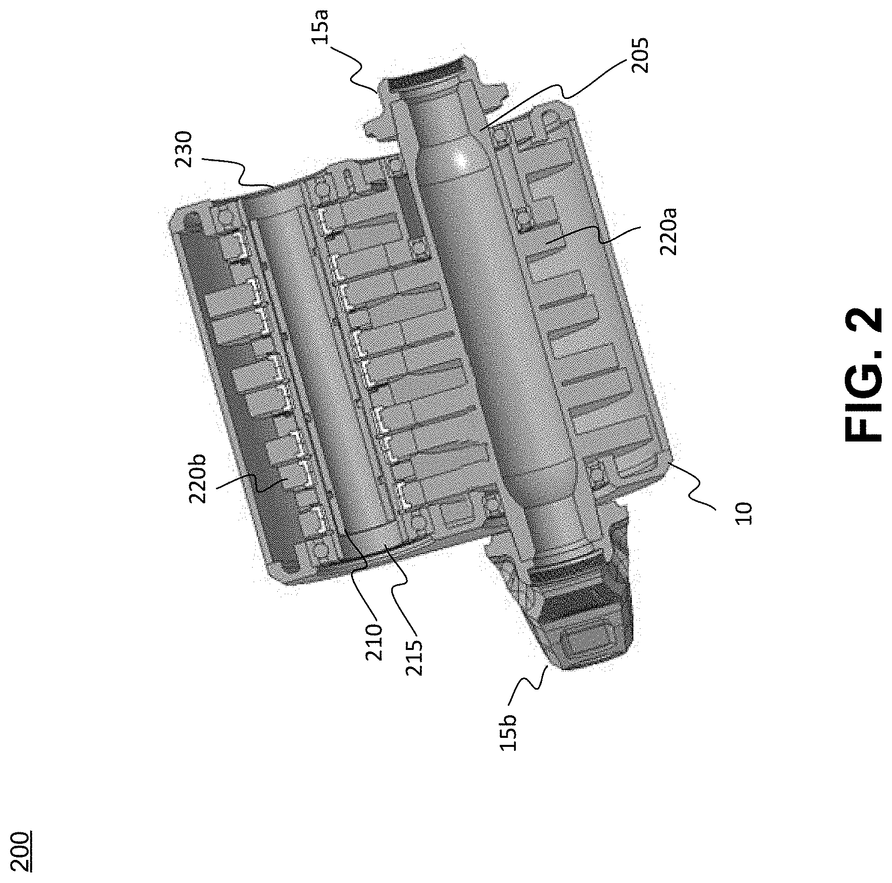
[0017] With reference now to FIG. 2, a sectional view 200 of the mid-sprocket assembly 10 is shown in accordance with an embodiment. In one embodiment, mid-sprocket assembly 10 includes an input shaft 205 (connected to the crank arms 15a and 15b) with one or more gears 220a directly attached to it and a countershaft 215 and a shifting shaft 210 that is selectively choosing which gear 220b is engaged to the countershaft 215. In one embodiment, in the case of spur gear driven assemblies there is a need for a third shaft 230 (the top shaft) to reverse the direction back to the appropriate direction. E.g., if the bike is being pedaled forward, the countershaft 215 is rotating backwards, and the third shaft 230 is needed to translate that power back into the forward direction. In one embodiment, the third shaft 230 is concentric about the countershaft 215. In another embodiment, the third shaft 230 is concentric about the input shaft 205. Although gears are shown, it should be appreciated that the power transmission could be performed with belts, chains, spur gears, etc. and any number of shafts could be utilized.
[0018] In one embodiment, power is input through the input shaft 205 (via the crank arms 15a and 15b, a motor, etc.), translated through all of the gears 220a and 220b to the countershaft 215, where one of the gears 220b on the countershaft 215 is selectively engaged to transfer the power into the countershaft 215 and then back out of the countershaft 215 into the output shaft (e.g., third shaft 230) which will have an output gear selected for use to provide the drive to the rear wheel. In another embodiment, the mid-sprocket assembly 10 does not include an output shaft and instead the power is transferred to the rear wheel directly from the countershaft 215. For example, In the case of an internal belt or chain drive where the drive is not reversed, it could be advantageous to have the output be direct from the countershaft 215 to differently direct chain forces on a bike to tune anti-squat characteristics and to simplify the internals of the mid-sprocket assembly 10.
[0019] Referring now to FIG. 3, a sectional view 300 of the gear engagement/disengagement of the mid-sprocket assembly is shown in accordance with an embodiment.
[0020] Present gearbox assemblies use radially acting pawls with a radial interface, that are selectively engaged. However, because of the radial space restrictions of a gearbox, the pawls are housed centrally inside the countershaft. In this configuration, the gearbox does not shift well under load. Instead, some amount of decrease in the amount of input torque is needed to move the gear out of the gear that it is currently in and into the new chosen gear. Normally, all of the gears are always engaged, and the gear selection refers to which of the gears will be linked to the countershaft so that the power can be transferred to the countershaft and then out through the output shaft. In many cases, they are done with radial pawls which don't like moving when they are under load.
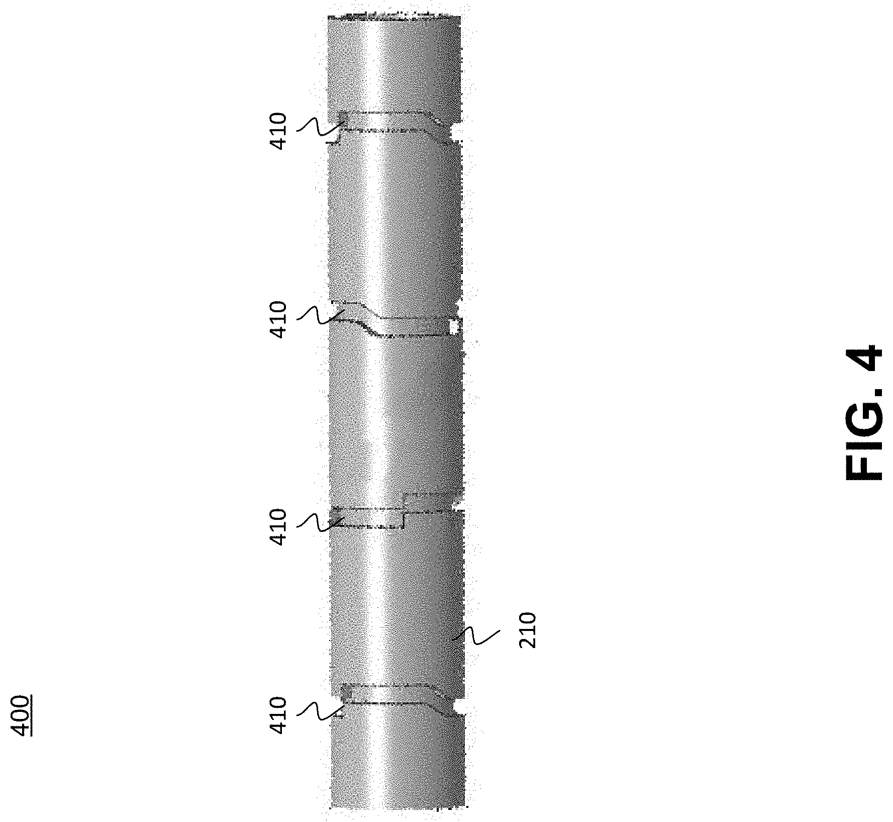
[0021] However, in the mid-sprocket assembly 10, a mechanism is used where each of pawls have spaces or shift rings 310 such as in FIG. 3 where gear 220b3 (and not gears 220b1 or 220b2) is engaged. In one embodiment, each of the shift rings 310 have pawl space angles and spaces that can vary. Moreover, the pawl geometry on the shift rings 310 has a design such that under-load they always want to disengage. Thus, the natural state of the shift rings 310 would be a neutral or disengaged state. The shifting shaft 210 inside the countershaft 215 utilizes a cam feature (as shown by the cam pin 325) that interfaces with a camming slots 410 feature in the shift shaft 210 which holds the shift rings 310 in place.
[0022] Referring now to FIG. 4, a side view 400 of the shifting shaft 210 including the camming slots 410 is shown in accordance with an embodiment. In general, camming slots 410 on shifting shaft 210 are offset accordingly to engage the appropriate (or different) shift rings 310 based upon the orientation of shifting shaft 210.
[0023] In the prior art, a pawl is locked in under load such that an attempt to change the gearing under load is difficult, if not impossible, and is likely to damage the pawl, wear out the gears, etc. In other words, the prior art pawls have a desire to remain engaged. While the embodiments disclosed herein have a natural resting state that is neutral or disengaged.
[0024] In one embodiment, (as shown in FIG. 2) shifting shaft 210 is retained from shifting right or left axially with a retaining feature (angular contact ring, or thrust bearing) on either end of the shifting shaft 210 that could be a bearing or the like that will hold the shifting shaft 210 with an amount of force that can also allow shifting shaft 210 to move axially based on the camming slots 410.
[0025] With reference now to FIG. 5, an orthogonal view 500 of countershaft 215 that includes the teeth 555 for engaging with the interior splines 655 of a shift ring 310 is shown in accordance with an embodiment. In one embodiment, the protrusions from the counter shaft only move axially in relation to the shift ring 310. Further, the mating faces on each of the shift ring could be referred to herein as either "splines" or "pawls." In one embodiment, the bushing on the gear rings are slotted so that they can pass over the splines 655 during assembly and then spin freely around the shifting shaft 210 once in the correct places axially.
[0026] Referring now to FIG. 6A, an orthogonal view 600 of a shift ring 310 with side pawls 610 for engaging with gears 220b and a cam pin hole 625 for engagement with cam pin 325 is shown in accordance with an embodiment. With reference now to FIG. 6B, a side view 650 of the shift ring 310 with side pawls 610 (or teeth) for engagement with gears 220b and inner circumference splines 655 for engagement with teeth 555 of countershaft 215 is shown in accordance with an embodiment.
[0027] In one embodiment, unlike a radial pawl gear ring that may have 10-24 pawls, the present axial embodiment has 60 pawls 610 on the shift rings 310. In one embodiment, there may be a similar number and shape of the pawls on the gears 220b. Thus, the amount of play during a shift when there is a disengagement of a first gear and an engagement of another different gear is significantly reduced. For example, the number of pawls divided by 360 provides the number of degrees of free play during a gear shifting process. In a prior art 24 pawl gear ring, the amount of free play would be 15 degrees that would occur during a disengagement of a first gear ring and the engagement of a second gear ring. In contrast, in the present 60 pawl 610 shift ring 310 there would only be 6 degrees of free play during a gear ring change situation, e.g., a disengagement of a first gear ring and the engagement of a second gear ring.
[0028] In one embodiment, because of the additional number of pawls 610, there is also a force reduction between the pawl interfaces 333 as shown in FIG. 3. That is, the force on the shift rings 310 and gears 220b is shared across the 60 pawl 610.
[0029] In one embodiment, because of the resting neutral aspects of each shift ring 310 and the configuration of gears 220b, the face of the pawls 610 can be sharp on both sides (e.g., a steep face angle on each side). Which allows the pawls to be much smaller in size and therefore capable of having more pawls 610 on shift rings 310 and gears 220b (as they do not need to have a shallow face on one side of the pawls 610 to deal with a free rotating need of a prior-art gear ring). Although a number of pawls 610 is shown, the number of pawls 610 could be different. Moreover, although a shape of the pawls 610 faces is shown, the faces could be different to provide different friction/retaining characteristics.
[0030] In one embodiment, because the pawl faces on the shift rings and gears are symmetric, the gears 220b could be set to be loaded even when the input from the pedals is backwards which would allow the mid-sprocket assembly 10 to become a direct drive. In one embodiment, the freewheel could only be at the rear hub instead of at the mid-sprocket assembly 10 which would reduce the weight, complexity, and the like of the mid-sprocket assembly.
[0031] In one embodiment, the rear hub could be a direct drive hub and the mid-sprocket assembly 10 could include the freewheel capability to reduce the weight, size, complexity of the rear wheel of the bike.
[0032] In one embodiment, because of the symmetry of the pawls 610 on the shift rings 310 and the gears 220b, the different freewheel and direct drive configurations described above could be made by the simple swapping out different rear wheels and/or making an adjustment to the mid-sprocket assembly. In so doing, a rider could make a quick pit-stop and change a bike to any of the different configurations.
[0033] In one embodiment, the main driving torque of the system is carried by the splines in the countershaft directly. In one embodiment, shift rings 310 are transferring a force into the countershaft via the shaft pin, while the remaining gears are spinning on the spline free portion about the countershaft.
[0034] Although a number of components are shown in the above figures, it should be appreciated that the components of the mid-sprocket assembly could be fixed or could be interchangeable. For example, a given gear ring could be changed, a plurality of gear rings could be changed, similarly, the countershaft, shift ring, cam pins, and the like could also be fixed or interchangeable to allow for different gearing scenarios, different gear numbers, etc. Further, one or more of the components could be adjusted, modified, removed, added, or exchanged for personal reasons, for performance reasons, for different applications (e.g., road, downhill, offroad, uphill, etc.), for different size bike frames, different crank arms, different chainring designs, and the like.
[0035] The foregoing Description of Embodiments is not intended to be exhaustive or to limit the embodiments to the precise form described. Instead, example embodiments in this Description of Embodiments have been presented in order to enable persons of skill in the art to make and use embodiments of the described subject matter. Moreover, various embodiments have been described in various combinations. However, any two or more embodiments could be combined. Although some embodiments have been described in a language specific to structural features and/or methodological acts, it is to be understood that the subject matter defined in the appended claims is not necessarily limited to the specific features or acts described above. Rather, the specific features and acts described above are disclosed by way of illustration and as example forms of implementing the claims and their equivalents.
* * * * *
D00000
D00001
D00002
D00003
D00004
D00005
D00006
XML
uspto.report is an independent third-party trademark research tool that is not affiliated, endorsed, or sponsored by the United States Patent and Trademark Office (USPTO) or any other governmental organization. The information provided by uspto.report is based on publicly available data at the time of writing and is intended for informational purposes only.
While we strive to provide accurate and up-to-date information, we do not guarantee the accuracy, completeness, reliability, or suitability of the information displayed on this site. The use of this site is at your own risk. Any reliance you place on such information is therefore strictly at your own risk.
All official trademark data, including owner information, should be verified by visiting the official USPTO website at www.uspto.gov. This site is not intended to replace professional legal advice and should not be used as a substitute for consulting with a legal professional who is knowledgeable about trademark law.