Brake System
LEIBER; Thomas ; et al.
U.S. patent application number 16/624505 was filed with the patent office on 2020-06-04 for brake system. The applicant listed for this patent is IPGATE AG. Invention is credited to Heinz LEIBER, Thomas LEIBER, Anton VAN ZANTEN.
| Application Number | 20200172068 16/624505 |
| Document ID | / |
| Family ID | 59887205 |
| Filed Date | 2020-06-04 |


| United States Patent Application | 20200172068 |
| Kind Code | A1 |
| LEIBER; Thomas ; et al. | June 4, 2020 |
BRAKE SYSTEM
Abstract
A brake system may include an actuation device, in particular a brake pedal; a first piston-cylinder unit with two pistons, in particular an auxiliary piston and a second piston, in order to supply brake circuits with a pressure medium via a valve device, wherein one of the pistons, in particular the auxiliary piston, can be actuated by means of the actuation device; a second piston-cylinder unit comprising an electric motor-powered drive, a transmission, and at least one piston in order to supply pressure medium to at least one of the brake circuits via a valve device; and a motor pump unit with a valve device in order to supply pressure medium to the brake circuits. The brake system may further include a hydraulic travel simulator which is connected to a pressure or working chamber of the first piston-cylinder unit.
| Inventors: | LEIBER; Thomas; (Rogoznica, HR) ; LEIBER; Heinz; (Oberriexingen, DE) ; VAN ZANTEN; Anton; (Ditzingen, DE) | ||||||||||
| Applicant: |
|
||||||||||
|---|---|---|---|---|---|---|---|---|---|---|---|
| Family ID: | 59887205 | ||||||||||
| Appl. No.: | 16/624505 | ||||||||||
| Filed: | August 30, 2017 | ||||||||||
| PCT Filed: | August 30, 2017 | ||||||||||
| PCT NO: | PCT/EP2017/071738 | ||||||||||
| 371 Date: | December 19, 2019 |
| Current U.S. Class: | 1/1 |
| Current CPC Class: | B60T 17/221 20130101; B60T 2270/10 20130101; B60T 8/4022 20130101; B60T 2270/402 20130101; B60T 13/662 20130101; B60T 13/16 20130101; B60T 13/58 20130101; B60T 2270/404 20130101; B60T 2270/403 20130101; B60T 2270/604 20130101; B60T 8/4036 20130101; B60T 8/4081 20130101; B60T 8/176 20130101; B60T 8/268 20130101; B60T 8/4018 20130101; B60T 13/745 20130101; B60T 2270/413 20130101 |
| International Class: | B60T 8/40 20060101 B60T008/40; B60T 17/22 20060101 B60T017/22; B60T 13/58 20060101 B60T013/58; B60T 13/16 20060101 B60T013/16; B60T 13/66 20060101 B60T013/66; B60T 8/176 20060101 B60T008/176 |
Foreign Application Data
| Date | Code | Application Number |
|---|---|---|
| Jun 20, 2017 | DE | 102017113563.4 |
Claims
1.-26. (canceled)
27. A brake system, comprising: an actuating device, a first piston-cylinder unit having a first piston and a second piston, arranged to supply at least one first brake circuit and at least one second brake circuit with pressure medium via a valve device, wherein the first piston is enabled to be actuated by means of the actuating device, wherein the first piston-cylinder unit comprises a first pressure chamber or a first working chamber in which the first piston is arranged and to which at least the second brake circuit is connected, wherein the first piston-cylinder unit comprises a second pressure chamber or a second working chamber, to which at least the first brake circuit is connected, a second piston-cylinder unit with an electromotive drive, a transmission and at least one piston for supplying pressure medium to at least one of the brake circuits via a valve device, a motor-pump unit, with a valve device, arranged to supply pressure medium to the first and second brake circuits, a hydraulic travel simulator connected to one of the first or second pressure chambers or working chambers of the first piston-cylinder unit, wherein a pressure or working chamber of the second piston-cylinder unit is connected to the first brake circuit via a hydraulic line and is supplied with pressure via the first piston, and wherein the second piston-cylinder unit is aligned parallel to the axis of the first piston-cylinder unit.
28. The brake system according to claim 27, wherein the brake system is designed for a subsequent conveying of volumes from a storage container during the piston return stroke of the second piston-cylinder unit via a suction valve, wherein the suction valve and a breather hole of the second piston-cylinder unit are connected to the storage container via a return line.
29. The brake system according to claim 27, wherein the first piston-cylinder unit has a partition wall with a seal for a penetrating plunger, for forming a third pressure chamber or a third working chamber, in which a piston is arranged, which is connected via a valve device to a brake circuit.
30. The brake system according to claim 29, wherein, in the event of failure of the first brake circuit, the plunger transmits force of the actuating device to the second piston and thus generates pressure in the second brake circuit.
31. The brake system according to claim 30, wherein the plunger has a smaller cross-sectional area than the first and second pistons of the first piston-cylinder unit, by at least a factor of 5, and contributes insignificantly to pressure build-up and serves for pressure sensing in at least one of the brake circuits, and the plunger further transmits a force to the actuating device and thus generates a haptic feedback to the actuating device.
32. The brake system according to claim 27, further comprising a control device arranged to enable a motor of the electromotive drive of the second piston-cylinder unit and a motor of the motor-pump unit to be used together or independently of one another.
33. The brake system according to claim 27, wherein, in the event of failure of the motor-pump unit, an ABS function is carried out by a piston control of the second piston-cylinder unit together with pressure regulating valves of the motor-pump unit.
34. The brake system according to claim 27, wherein the second piston-cylinder unit is only effective in a specific pressure range, and wherein the motor-pump unit is used for pressure generation for a further, higher pressure range.
35. The brake system according to claim 27, wherein control of the second piston-cylinder unit is carried out via travel of the actuating device and control of pressure is carried out by means of a corresponding brake booster characteristic, wherein instead of the pressure, the motor current is used for regulating the second piston-cylinder unit.
36. The brake system according to claim 27, wherein a pressure-volume characteristic is used for controlling the second piston-cylinder unit and for diagnosis, wherein the brake system is designed to detect a failure of one of the brake circuits by comparing pressure-volume characteristics, wherein the pressure-volume characteristic is stored in a characteristic map at intervals as part of a diagnostic cycle.
37. The brake system according to claim 27, wherein the first piston and the second piston of the first piston-cylinder unit have different diameters.
38. The brake system according to claim 27, further comprising a two-box, wherein a first module of the two-box is connected to a 12V battery or 12V voltage network and a second module of the two-box is connected to a DC/DC converter or other on-board network with a higher voltage than 12V.
39. The brake system according to claim 38, wherein both of the first and second modules of the two-box are each connected redundantly both to the 12V battery or voltage network and to the DC/DC converter or other on-board network with a higher voltage than 12V.
40. The brake system according to claim 27, wherein four-wheel blending takes place for a recuperation control, wherein a pressure control takes place via a piston with open valves of the valve device of the motor-pump unit, and/or wherein the transmission comprises a trapezoidal spindle with self-locking, having a self-locking action in the event of failure of the electromotive drive.
41. The brake system according to claim 27, wherein a plug connection for the brake system is arranged below a storage container and is directed inwards towards a center of the brake system in order to enable a lateral removal of an associated plug.
42. The brake system according to claim 27, wherein the second piston of the first piston-cylinder unit has, in addition to a passage in form of a breather hole which is provided with two seals, a further passage which is provided with a further seal, and which is connected via a throttle to a line leading to a storage container.
Description
[0001] The invention relates to a brake system according to the preamble of claim 1.
DESCRIPTION OF THE PRIOR ART
[0002] The trend towards vehicles with autonomous driving (AD) places high demands on the brake system in terms of fault tolerance on the one hand and redundant functions, e.g. for brake pressure generation, power supply and computer functions (ECU) on the other. So-called one-box and two-box systems are favored. The latter consist of an electric brake booster (BKV), a so-called e-booster, and an ESP system (Electronic Stability Control System). This makes, for example, the generation of brake pressure via electric motor and electronic control unit (ECU) redundant for e-boosters and return pumps with electric motor and ECU.
[0003] The known solutions have relatively long overall lengths and a high weight.
[0004] In WO2011/098178 (hereinafter referred to as variant A or as a follow-up booster or e-booster), such a solution is described with a coaxial drive in which an electric motor acts via a gear and piston on the HZ piston (=main cylinder piston). The BKV control is effected via an electrical element and reaction disc as a so-called follow-up booster, the pedal travel is a function of the brake pressure and the volume absorption of the brake system, which requires long pedal travel in the event of fading or brake circuit failure.
[0005] WO2009/065709 (hereinafter referred to as variant B, or as a follow-up booster or e-booster) also shows an e-booster as a follower BKV. Here the BKV control takes place via pedal travel and pressure. A separate pressure supply with electric motor and plunger acts via the amplifier piston on the HZ piston.
[0006] WO2012/019802 (hereinafter variant C) shows an arrangement similar to WO2011/098178 with coaxial drive in which an electric motor acts on the HZ piston via a gear and piston. An additional piston cylinder unit is used here, which acts on a travel simulator piston (WS). The pedal travel is thus independent of e.g. fading and brake circuit failure. However, the complexity and the construction length are high.
[0007] DE 10 2009 033 499 (hereinafter also referred to as variant D) shows a brake booster (BKV) with additional ESP unit with hydraulic actuation of the booster piston and external pressure supply. This arrangement with four or five pistons and six solenoid valves (MV) is complex and unfavorable in length. The non-hydraulically acting travel simulator (WS) is located within the piston-cylinder unit upstream of the main cylinder and cannot be damped or switched via a solenoid valve (MV).
[0008] All above mentioned solutions have a redundant brake booster (BKV) function, because in case of failure of the BKV motor the ESP unit with pump similar to the assistance functions with vacuum BKV guarantees the brake function in autonomous driving mode.
[0009] In the event of failure of the ESP motor, ABS shall function via the possibility of pressure modulation by the BKV motor as described in WO2010/088920 of the applicant. However, this only allows a common pressure control for all four wheels, which does not result in an optimal braking distance.
[0010] All previously known one-box systems have a so-called travel simulator (especially for brake-by-wire) because of the advanced pedal travel characteristics.
OBJECT OF THE INVENTION
[0011] Based on the prior art, it is the object of the present invention to provide an improved brake system.
[0012] In particular, the invention is based on the object of creating a brake system for use in autonomous driving operation (hereinafter AD) and/or electric vehicles/hybrid vehicles with increasingly strong recuperation power (energy recovery by braking via generator/or drive motor in generator operation). Preferably, the weight is reduced and/or the dimensions of the system are reduced and/or the reliability is increased.
[0013] Preferably, a cost-effective brake system for autonomous driving is to be created, which fulfils all required redundancies as well as very high safety requirements.
Solution According to the Invention
[0014] This object is solved according to the invention with the features of patent claim 1.
[0015] Among other things, the improvement is characterized in that the design of the brake booster has very few simple components with low tolerance requirements (e.g. valves only in open/closed operation) and is therefore cost-effective, very short and narrow in design and enables a constant pedal travel characteristic, especially with strong recuperation.
[0016] Advantageous embodiments or designs of the invention are contained in the further claims, the drawing and the figure description to which reference is made here.
[0017] With the solution according to the invention and its embodiments and designs, a brake system is created which has a very short construction as well as an advantageous pedal characteristic.
[0018] In particular, a two-box system is created according to the invention, having an electric brake booster which is connected to a standard ESP unit via two hydraulic lines (hereinafter referred to as X-Boost and ESP/ABS unit, together referred to as two-box system), wherein the brake booster has a pedal characteristic which is independent of the volume absorption of the brake system and the degree of recuperation.
[0019] Furthermore, the invention achieves a compact design of the brake booster with a low box volume, which is very short and narrow and has many redundancies, e.g. for pressure generation, electrical supply, failure of the pump motor of the ESP unit and also includes an ABS function with reduced performance in the event of failure of the ESP unit. In emergency operation without ESP, the ABS function should include at least one individual regulation axle-by-axle to improve the braking distance ("select-low" pressure regulation).
[0020] The installation spaces in the unit compartment are becoming smaller and smaller, thus the dimensions of the brake unit should be as small as possible, especially in terms of width and length. This compact design is possible on the one hand by decoupling the main cylinder (HZ) piston from the motor drive and on the other hand by a special short main cylinder (HZ) according to WO2016/023994 of the applicant, which is referred to here with parallel arranged pressure supply (hereinafter pressure supply or DV) consisting of electric motor with piston drive.
[0021] The pressure supply (DV) is only effective up to the wheel locking limit of 80 to 100 bar. For higher pressures (e.g. for driver assistance functions), the pump of the ESP unit is switched on. This can therefore be realized with the solution according to the invention in comparison to variant A of the prior art described above, since the ESP pump function has no influence on the pedal feel, since the brake pedal is decoupled.
[0022] In the pedal characteristic, a retroactive effect from volume absorption, e.g. in the event of brake circuit failure, should be excluded. On the other hand, it should be possible to generate a desired pedal feedback, e.g. a small pedal movement when using the ABS function, optionally also intermittently. Faults, e.g. brake circuit failure, can also be indicated by moving the pedal parallel to the warning lamp.
[0023] Various solutions are conceivable for the pedal travel simulator. In the entire pressure range (150 to 200 bar) the pedal travel simulator should deliver a good pedal travel characteristic, e.g. up to 30 bar with a flat characteristic curve and then progressively increasing without influence whether the X-Boost or the ESP unit delivers the pressure. In the embodiment of the e-booster as a follow-up booster (variant A according to the prior art), the pedal force characteristic curve changes significantly during the transition from e-booster to ESP and requires a lot of software effort for the PWM operation of the valves necessary for this. This is not the case with the solution according to the invention, since the operation of the ESP pump has no influence on the pedal characteristics, since the pedal is decoupled via the travel simulator.
[0024] To reduce the construction volume, the return spring (18) can be used in the flat part of the pedal travel characteristic curve, so that the volume in the piston travel simulator is smaller and only corresponds to the progressive part of the characteristic curve, as also shown in WO2013/072198 of the applicant, to which reference is made here.
[0025] Another possibility for the realization of a pedal travel simulator is a THZ (=tandem main brake cylinder) with plunger without piston travel simulator as described or illustrated in WO2016/023994 of the applicant, to which reference is made here in this respect. Here, the control pressure to the BKV, which depends on the pedal travel, acts on the plunger and thus generates the pedal feedback effect.
[0026] Depending on the pedal position, pressure is transmitted from the piston of the pressure supply to the SK piston of the main brake cylinder (T)HZ, which creates the brake pressure. The pressure supply consists of an electric motor which drives the piston via a spindle. Both a ball screw drive (KGT) and a trapezoidal spindle with nut can be used as transmissions. The latter is cheaper and quiet, but has a lower efficiency and is self-locking. The latter has the advantage that in the event of a failure in the pressure supply DV, e.g. of the engine, the piston remains in the position so that there is no increase in volume in the brake circuit under the influence of brake pressure.
[0027] For the ball screw drive (KGT), an additional shut-off valve must be used for this failure. The aspiration of the liquid from the storage container (VB) takes place via a suction valve or via the piston sleeve seal with a breather hole, as in a main cylinder (HZ).
[0028] Access to the piston travel simulator can be closed with a solenoid valve (WA), as in the event of a pressure supply failure (DV) the pedal force acts on the main cylinder (HZ) and thus generates brake pressure in the so-called fallback level (RFE). Without the valve (WA), the pedal travel in the fallback level (RFE) would be extended by the volume absorption of the piston travel simulator (WS).
[0029] Since the interconnection of X-Boost and ESP unit provides two redundant systems for pressure generation with redundant power supply, the fallback level (RFE) is only effective during towing, actually only for deep loading, e.g. in the event that the transmission of the vehicle may be blocked. These facts allow greater degrees of freedom in system and piston design, e.g. saving a WA solenoid valve.
[0030] X-Boost and ESP unit have separate power supplies in one embodiment, e.g. ESP is connected to a 12V battery and X-Boost is connected to a DC/DC converter of a multi-voltage vehicle electrical system. Alternatively, both X-Boost and ESP unit can be connected to both 12V battery and DC/DC converter. Thus both modules of the brake system of the two-box have a redundant power supply in each case.
[0031] Some of the solutions according to the invention have even more advantages over the prior art variant A: [0032] I. If the brake circuit fails, there is no pedal through fall; [0033] II. If the ESP motor fails, the pressure can also be controlled axle by axle, which enables a considerable reduction in braking distance; [0034] III. Many driver assistance functions can be implemented in X-Boost and can be implemented with greater precision than in the ESP unit; and/or [0035] IV. Recuperation control is easier, quieter and more accurate by control via the DV than via inlet and outlet valves and the pump of the ESP unit.
[0036] Pedal through fall I) can thus be avoided, since a leak in the system has no effect on the pedal feeling, since the travel simulator is decoupled. In contrast to the solution according to the invention, a leak in the system has a direct effect on the pedal feeling in variants A and B, for example, so that in the worst case the pedal travel is suddenly extended and the change cannot be controlled by the driver and leads to accidents.
[0037] The individual pressure regulation II) of axles is made possible by the solution according to the invention because in the event of failure of the ESP motor, the electric motor of the pressure supply DV of the X-Boost takes over the pressure regulation and the pressure regulation has no influence on the pedal. This means that there are considerably more degrees of freedom than with follow-up booster solutions (variants A and B). For this purpose, the pressure control of the invention via the piston travel and motor current in accordance with (DE 10 2005 018649 of the applicant) and pressure gradient regulation (DE 10 2005 055751 of the applicant), to which reference is made here in this respect, is used for a high-precision pressure control which cannot be achieved with pulse width modulation (PWM) control of valves of the ESP unit.
[0038] The system decoupling (pedal of the system) is also of great importance for the implementation of III) driver assistance functions, as described in more detail below.
[0039] Recuperation control (IV) is becoming increasingly important due to the increasing hybridization and spread of electric vehicles. The brake pressure is varied depending on the possible generator braking effect and the total braking effect required from the driver. This is called brake pressure blending.
[0040] The recuperation control (IV) for one of the solutions according to the invention is carried out exclusively via the piston travel control of the pressure supply DV, e.g. in four-wheel blending. Depending on the deceleration effect of the generator of the vehicle or the drive motor of an electric vehicle operated in generator mode, a corresponding braking pressure is set by adjusting the piston so that the sum of the hydraulic braking force and the braking effect by the drive motor results in the desired total deceleration force.
[0041] This is possible in a completely variable manner, as the pressure position of the pressure supply DV of the X-Boost has no effect on the pedal feel. This has considerable advantages, especially compared to the variants A and B of the prior art, where the coupling between the pedal and the HZ volume means that the storage chambers of the ESP unit have to be emptied in order to achieve a reduced deceleration while maintaining the same pedal feel. This requires an intervention in ESP and a very complex control of the outlet valves of the ESP unit. In addition, with some of the solutions according to the invention, different ESP variants for different brake circuit distribution (diagonal and parallel/brake circuits axle by axle, rear and front drives) can be avoided, since control takes place exclusively via the piston, independent of the brake circuit distribution and the drive type. In particular, the following advantages of the X-Boost also result from the recuperation. Some of the solution approaches according to the invention offer the following advantages in the pedal feel compared to the prior art: [0042] No change in pedal feel due to blending [0043] No change in pedal feel due to changes in the brake system (e.g. changes in brake release clearance, changes in PV characteristic curve)
[0044] Blending offers the following advantages in summary: [0045] Precise adjustment of brake pressures, even with rapid changes in generator torque=>Simple point braking; [0046] No perceptible noises, e.g. from switching valves in the ESP unit; [0047] Blending in the entire vehicle deceleration range; [0048] Much simpler software for blending than conventional e-boosters; [0049] Brake force distribution can be displayed at will, up to the wheel lock limit. ESP interventions for vehicle stabilization, especially on slippery and uneven road surfaces, and interruptions of the recuperation process with complex switching from recuperation to purely hydraulic braking and vice versa, can thus be avoided; [0050] Changes to the wheel brakes (e.g. pressure-volume characteristics or p-V characteristics) on the non-driven axle have no influence on the hydraulic braking; [0051] No additional components required to hold hydraulic fluid (e.g. no "smart actuator"); [0052] No harder return spring required for pedal (important for P.sub.max in RFE); and/or [0053] Changes in the PV characteristic curve of the brake system are diagnosed.
[0054] In known systems according to variant A with follow-up booster, the pedal travel is a function of the volume take-up. To prevent the pedal travel from becoming large during normal operation, it is necessary to adjust the dimensions of the main cylinder HZ for different vehicle types with different piston diameters. In the event of a system failure in the fallback level RFE, this leads to high pedal forces with the same pedal travel in brake systems with greater volume absorption. In accordance with the requirements of ECE-13H, a vehicle deceleration of at least 0.24-0.3 g is required for a maximum foot force of 500 N.
[0055] Some of the solutions according to the invention allow the use of a small auxiliary piston diameter in comparison to the SK piston and thus higher brake pressures in the fallback level RFE at 500 N foot force. In addition, the volume in the brake circuits can be further increased with brake fading in that DV continues to convey. This additional volume must be able to be transferred from the SK piston into the floating circuit, either by a larger diameter of the SK piston than the auxiliary piston or by a larger travel of the SK piston.
[0056] The BKV is controlled in one embodiment in accordance with DE 10 2005 018649 and DE 10 2005 055751 of the applicant, to which reference is made here, via the piston of the pressure supply DV by applying a pressure in the brake circuit via a BKV characteristic curve as a function of the pedal travel. The pressure is measured in the ESP unit and provided by the pressure supply DV via a corresponding piston travel. If the pressure sensor fails, this pressure signal is not available. The pressure sensor failure is detected by the pressure supply DV via evaluation of the pressure volume characteristic curve (p-V characteristic curve). Here the corresponding pressure value is missing for the piston travel.
[0057] The current measurement of the DV motor can also be used here as a replacement for the pressure measurement. In general, it is also conceivable to use only current measurement. For the corresponding accuracy for pressure build-up and reduction, the hysteresis must be included in the characteristic curve of the pressure supply DV (piston travel and pressure or current alternatively) by the friction forces in the drive, optionally with correction values, e.g. by correlation of the current with the vehicle deceleration.
DESCRIPTION OF THE DRAWINGS
[0058] Further features and advantages of the invention result from the following description of embodiment examples of the invention and their design.
[0059] The drawings show as follows:
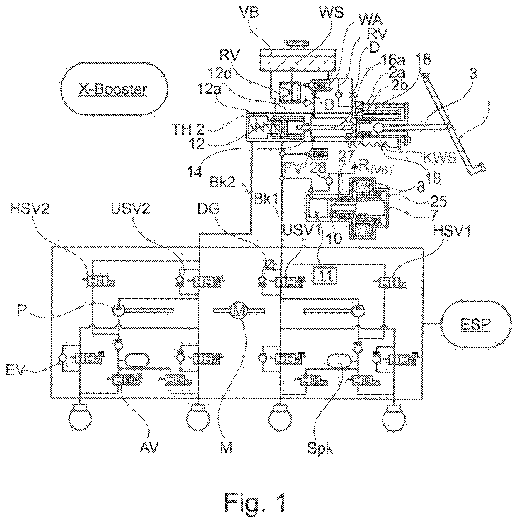
[0060] FIG. 1: Complete X-Boost system with ESP;
[0061] FIG. 1a: THZ main cylinder with pressure supply DV and piston travel simulator KS;
[0062] FIG. 1b: An exemplary detail design of the first piston-cylinder unit;
[0063] FIG. 2: Pedal characteristics;
[0064] FIG. 3: Main components of the system.
[0065] FIG. 1 shows a schematic diagram of the brake system with an actuating device, in particular brake pedal 1, a first piston-cylinder unit THZ, which can be actuated by means of the actuating device, a second piston-cylinder unit with an electromotive drive and a transmission (hereinafter also X-Boost or booster) and an ABS/ESP unit. The ABS/ESP unit is known with the main components pump P with motor M, valves HSV1 and HSV2, USV1 and USV2, inlet and outlet valves EV and AV assigned to the wheel brakes, and storage chamber (SpK). This system is described in many publications and patent applications. It is already on the market as an e-booster and is mainly used in electric and hybrid vehicles, because here the brake system is controlled in conjunction with the braking torque of the generator, i.e. recuperation. As is well known, both the e-booster and the ESP elements can play a role here, especially in the pedal characteristics. Another field of application is vehicles with autonomous driving. The focus here is on error safety and redundancy of the functions, such as pressure supply and ABS function. The main difference in system design is the new X-Boost concept. This consists of a special main cylinder HZ with travel simulator WS and pressure supply DV, which is arranged parallel or perpendicular to the main cylinder HZ in order to achieve a short overall length, see also FIG. 3.
[0066] The main cylinder HZ essentially consists of an auxiliary piston (HiKo) 16 and a floating piston (SK piston) 12 with return spring 12a. The auxiliary piston 16 is connected to a plunger 16a, which acts through a partition wall 14 with seal into the pressure chamber 12d. A distance of approx. 50% of the travel of the auxiliary piston (HiKo) 16 is between the end of the plunger and the SK piston. The plunger 16a has a significantly smaller cross-sectional area than the pistons of the first piston-cylinder unit (>factor 5 smaller) and contributes insignificantly to pressure build-up and pressure sensing in the brake circuit and transmits this force to the brake pedal, thus generating a haptic feedback to the brake pedal, especially during ABS operation and/or fading.
[0067] Normally, a valve FV is closed at the start of braking and the auxiliary piston HiKo acts on the travel simulator WS, whose function and variants are described later. The auxiliary piston HiKo has two functions: for normal operation and for a fallback level in the event of a failure of the pressure supply DV. In the first case, normal operation, it feeds the travel simulator WS with the valve FV closed, and the pedal travel is the input signal for the pressure supply DV. At the fallback level, when the pressure supply DV fails, it also feeds the travel simulator WS when the valve FV is closed, but the pedal travel is now the input signal for the ESP booster.
[0068] When brake pedal 1 is actuated with pedal plunger 3, redundant pedal travel sensors 2a/2b are activated simultaneously. These can additionally be decoupled via an elastic member KWS, as described in DE 11 2011 103274 of the applicant, to which reference is made here in this respect. Advantages are on the one hand detection when the auxiliary piston (HiKo) 16 is blocked, and on the other hand the differential travel of the sensors when the auxiliary piston (HiKo) 16 is blocked provides a control signal for auxiliary braking. The elastic member can also be part of the spring characteristic of the WS travel simulator. The auxiliary piston (HiKo) 16 has a normal breather hole of a THZ piston which is connected to the storage container VB. It is well known that a brake circuit fails if the primary seal fails. This can be avoided by using a check valve RV which is used for venting and a throttle in the connection line to VB. The throttle is dimensioned with a small flow rate so that the pedal characteristic is not significantly changed (3 mm pedal travel in 10 s) if the seal fails and can still be diagnosed. The same arrangement can also be used for the floating piston (SK) 12 (not shown), which makes the failure of both seals uncritical. Alternatively, a normally open solenoid valve can also be used in the feedback line, which closes after pedal actuation or diagnosis. This applies to both pistons of the HZ (auxiliary piston HiKo and the second piston SK).
[0069] The travel simulator WS can be designed in different ways. The illustrated design corresponds to the prior art, which is described in various patent applications, consisting of a WS piston with spring combinations, which as a function of the pedal travel provide the pedal travel characteristics. The valve RV is used for the fast pressure reduction P.sub.ab from the travel simulator WS, if the pedal is released very fast, and the throttle D for the desired throttled pressure build-up P.sub.auf with the corresponding pedal characteristics. In addition, the travel simulator WS can be switched off via the valve WA. This is necessary for non-redundant systems in the fallback level (RFE) so that the intake volume of the travel simulator WS does not affect the delivery volume of the auxiliary piston HiKo to the brake circuit BK1 and pressure chamber 12d. With this system (FIG. 1) the ESP acts redundantly in case of failure of the X-Boost, where the ESP pump sucks volume from the storage container via the main cylinder THZ and the pressure supply DV. The valve WA can therefore be dispensed with. Another version is described in FIG. 1a. The auxiliary piston (HiKo) 16 with pedal plunger 16a is moved to the initial position by the pedal return spring 18 after brake actuation.
[0070] The pressure supply or DV is required for the BKV function. This consists of an EC motor 8, which moves a piston 10 via a spindle 7 and nut and delivers pressure medium into the brake circuit BK1 and the pressure chamber 12d. The dimensioning of the volume is derived from the BKV control, which controls a pressure from pedal travel 2a/2b via the BKV characteristic curve, which is measured by the pressure transducer DG in ESP. Alternatively, the motor current, measured via a shunt, can be used instead of the pressure. To improve the accuracy of the pressure control via the current measurement, this requires the recording of the friction losses in P.sub.auf and P.sub.ab in a characteristic map, optionally additionally improved by correction factors, e.g. by comparison with the vehicle deceleration. This is particularly important if the spindle drive is not a ball screw drive KGT, but a trapezoidal spindle with a plastic nut, for example.
[0071] In the starting position, the piston 10 has a breather hole 27 as in the main cylinder THZ. The volume can be sucked in via the sleeves or via a suction valve (SV) 28, which requires a lower vacuum to open and is temperature-independent.
[0072] If a trapezoidal spindle is used, the pistons remain in the position in which the motor drive no longer acts due to the self-locking of the pistons.
[0073] The dimensioning of the pressure supply DV can be staggered so that the full travel of the DV piston corresponds to the volume consumption of brake circuit BK2 or the travel of the SK piston 2. The SK piston can be designed larger in diameter and also in travel for larger volume intakes. The pressure supply DV, on the other hand, can be designed accordingly or smaller in volume (piston and travel) by making the missing volume possible by replenishing with piston return travel via the SV suction valve. For this a normally closed solenoid valve PD1 is required, which is not shown in FIG. 1 (see FIG. 1a). For full volume compensation in the event of pressure reduction P.sub.ab, the piston must be moved to its initial position with the breather hole open. The suction valve 28 and the breather hole 27 are connected to the return line to the VB. All components of the pressure supply DV are combined in one housing 25.
[0074] The pressure build-up P.sub.auf and pressure reduction P.sub.ab in brake circuit BK1 and brake circuit BK2 is achieved via the BKV control and pedal travel sensors, and the piston of the DV moves accordingly. Normally, the X-Boost pumps volume into the brake circuit BK up to the blocking limit 80-120 bar. At higher pressures, the ESP pump is switched on and generates a pressure build-up to approx. 200 bar with correspondingly lower output and thus slower than the pressure build-up with the X-Boost. This is permissible because the pressure build-up up to 200 bar is only relevant for fading cases and does not have to take place as quickly as the pressure build-up up to the blocking limit (e.g. for the implementation of emergency brake functions). The ESP pump is thus set to 200 bar, the X-Boost to 80-120 bar.
[0075] If the pressure supply DV fails during a braking process, the DV piston is pushed back under pressure in brake circuit BK1 so that the brake pressure can be completely reduced. If a self-locking gear is used for the DV piston (trapezoidal spindle with plastic nut), such a pressure reduction is not possible. In this case, a normally closed solenoid valve AV is provided in brake circuit BK1 with connection to the storage container (not shown) or in connection from the breather hole of the Hiko to the storage container VB.
[0076] In the event of failure of both electronic control or regulating units (ECU) of X-Boost and ESP, which occurs very seldom, volume is conveyed in the fallback level RFE by the auxiliary piston (HiKo) 16 to the brake circuit BK1 and to the main cylinder HZ on the rear side of the SK piston through the opened valve FV and the brake pressure is increased, wherein the brake pressure in the main cylinder HZ displaces the SK piston and the pressure in brake circuit BK2 increases. To prevent this volume from escaping through the opened breather hole of the DV, a normally closed solenoid valve PD1 is provided (not shown in FIG. 1, see FIG. 1a).
[0077] Function in Case of Brake Circuit (BK) Failure
[0078] The failure of a brake circuit is detected by the pressure supply DV by comparing the p-V characteristic curve of the brake system, which is stored in a characteristic map at certain intervals as part of a diagnostic cycle.
[0079] If, for example, the piston travel/volume is greater than the standard value, there is correspondingly air in the brake circuit BK or a leak. This can be identified via the p-V characteristic curve. In the event of a leak, the leak can be identified by closing the four valves EV one after the other, provided this is located outside the units, e.g. in the wheel cylinder. If this is the case, for example, in brake circuit BK1, the valves EV of brake circuit BK1 are closed. The pressure supply DV then acts via the SK piston into the brake circuit BK2 (corresponding description of the diagnostic logic in the patent applications DE 10 2015 106 089.2 and 10 2016 112 971.2, to which reference is made here in this respect). If this does not work, the pressure supply DV fails, and so does the brake booster BKV. In this case, the ESP pump acts as brake booster BKV in brake circuit BK2.
[0080] Failure of brake circuit BK2 does not result in failure of pressure supply DV, as the floating piston SK represents an important safety gate with separation of brake circuits BK1 and BK2.
[0081] In both cases, the pedal characteristics remain the same and there is no pedal through fall.
[0082] ABS Function in the Event of Pump/Motor Failure in ESP.
[0083] When the ABS pressure reduction signal P.sub.ab occurs, the DV control corrects the brake pressure to prevent the wheels from locking. A corresponding pressure reduction P.sub.ab in both brake circuits is necessary to prevent a wheel from one of the two brake circuits from locking. However, this does not mean an optimal braking effect. However, this can be improved.
[0084] For example, during wheel locking with corresponding pressure reduction P.sub.ab in one brake circuit, the other brake circuit cannot experience pressure reduction P.sub.ab by closing the valve USVs. This can be optimized with individual wheel regulation by modifying the valves EV without parallel check valve RV as described in the patent application DE 11 2009 004636 (E112) (to which reference is made here).
[0085] FIG. 1a shows the main cylinder (HZ) arrangement of FIG. 1 with changes in the travel simulator WS valve circuit. The travel simulator WS has the normally closed WA valve as bypass valve. According to FIG. 2, the piston-WS has the task, according to the pedal characteristic, of taking up a volume with a corresponding counterforce (pressure) on the auxiliary piston (Hiko) 16, which causes costs and size. The pedal and WS characteristics are flat in the lower pressure range. It makes sense to use the return spring 18 here, which accounts for approx. 40% of the volume of the WS, and the WS piston becomes smaller accordingly. The valve WA is opened at the start of braking. As a result, after a certain pedal travel at the end of range A (see FIG. 2), the valve WA is closed so that the more progressive part B+C is switched on.
[0086] The pressure supply DV here has an additional normally closed solenoid valve PD1. This is necessary if the DV piston is pushed back under pressure in the fallback level RFE and the corresponding volume is lost in brake circuits BK1 and BK2. Although this can be compensated by the large volume of the auxiliary piston HiKo, this has a negative effect on the pedal characteristics. When the DV piston returns to its initial position, the breather hole opens and brake fluid drains into the storage container. In the fallback level RFE, the valve PD1 is closed. The valve PD1 can be opened again during ESP interventions or ESP boost.
[0087] In area A (FIG. 2) it cannot be detected during braking whether the valve WA has a leakage. For this reason, regular diagnostics are provided, e.g. at the end of braking, when the pressure supply DV pressurizes the space of the auxiliary piston through the open valves PD1 and FV. The valve will not leak if the pressure does not decrease when the DV piston is in a constant position.
[0088] If the ECU of the X-Booster fails during braking, then the ESP-Booster has to take over the function of the brake booster BKV. For this purpose, the ESP must be able to draw volume from the VB storage container and return it to the VB storage container at the end of braking. In case of ECU failure, however, the valve PD1 is closed, so that the connection between ESP and storage container VB is interrupted by the breather hole of the pressure supply DV. With redundant power supply of the ECU, this failure will occur very rarely. If the ESP booster is nevertheless required, a normally closed solenoid valve (not shown) can be provided between brake circuit BK1 and storage container VB (valve AV, see description of FIG. 1).
[0089] In one embodiment example, a seal D4 is arranged in the cylinder of the floating piston SK 12.
[0090] FIG. 1b shows a further embodiment example of the cylinder, in which a further seal D4r is provided for the floating piston SK 12 as redundancy to the seal D4. If this seal fails, the brake circuit BK1 and the pressure supply DV will fail. In this case, the ESP unit takes over the task of pressure supply, i.e. pressure amplification. This can be avoided by the further seal D4r whose connection to the storage container is provided with a throttle as with the auxiliary piston (HiKo) 16. A failure of this seal does not result in a failure of the brake circuit BK1 or the pressure supply DV with the low leakage flow through the throttle. In addition, a diagnosis is possible with this arrangement advantageously.
[0091] FIG. 2 shows the pedal characteristics over the pedal travel S.sub.p. In area A, the force increase with curve 1 is relatively flat up to approx. 30 bar brake pressure, which corresponds to approx. 85% of all braking operations. This process can also be carried out via the pedal return spring. Then the more progressive part B acts up to the blocking limit, followed by the range of higher pressures, e.g. for fading. Here the driver should also feel that there has been a change in the brake system.
[0092] Curve 1 corresponds to the X-Boost with travel simulator WS. Without WS, i.e. with follow-up booster, curve 2 results where the pedal travel depends on the venting state or fading. Accordingly, there is a scattering (not shown) to 2a, which is even more extreme in the event of brake circuit (BK) failure. With the conventional e-booster the BKV is switched from e-booster to ESP booster at x. This changes the pedal characteristics. Without influencing the BKV control, at the same pressure and pedal force, the pedal with the main cylinder (HZ) piston would deliver further volume to the ESP pump until the pressure in the wheel cylinders has reached its target values and the volume is returned to the main cylinder HZ by overflowing the valves USVs.
[0093] A changed pedal characteristic with a larger pedal travel is achieved by reducing the amplification factor of the X-Boost, which results in the outlined scatter band. Additionally, the valves HSV1 and HSV2 can be modulated.
[0094] Here the X-Boost according to the invention with travel simulator WS behaves like curve A with corresponding progressive force increase as a function of the pedal travel.
[0095] Pedal Feedback at ABS
[0096] With the ABS function the pre-pressure supplied by the DV changes constantly. This can be felt as a small force change on the plunger 16a and thus on the connected pedal plunger 3, which is demanded by many brake specialists. This can be changed at the beginning of the ABS or intermittently during deceleration by briefly increasing the inlet pressure.
[0097] If the reaction is more noticeable, the FV valve can open and the control pressure of the DV acts directly on the auxiliary piston HiKo.
[0098] Recuperation with Travel Simulator WS
[0099] The pedal characteristic is determined by the travel simulator WS. Here, brake management with generator determines the proportion of generator braking torque (electrical braking torque) and braking pressure (hydraulic braking torque) for the required vehicle deceleration. Both quantities can be changed at will during deceleration. The calculation of the brake pressure during recuperation is preferably based on wheel force. The required total braking force (target braking force) on the wheels is determined from the pedal travel. If the target braking force can be applied electrically, then the hydraulic braking force is 0 N (braking pressure in the wheel cylinders 0 bar). If the target braking force exceeds the maximum possible electrical braking force, the difference between the target braking force and the electrical braking force is the hydraulic target braking force. The hydraulic target braking force is realized by the pressure supply DV by pressure generation in the wheel cylinders. For this purpose, the individual Cp values of the wheel brakes are used to calculate the target brake pressure, wherein the Cp value of a wheel brake represents the ratio of brake force to brake pressure. The target pressure is generated by a corresponding movement of the DV piston, wherein the pressure sensor of the ESP is used for the feedback of the piston movement. In this way, the pressure supply DV can set the target pressure both during pressure build-up and during pressure reduction. Due to the precise position control of the DV piston, the pressure setting is very accurate. The pressure control with the DV is also very quiet because no valves for P.sub.auf and P.sub.ab have to be actuated. Noise-causing valve and pump actuations of the ESP unit are not required. Furthermore, this recuperation control can be used uniformly for front, rear and all-wheel drive vehicles and X and II brake circuit splitting. The pedal characteristic remains unchanged.
[0100] Driver Assistance Functions
[0101] There are many driver assistance functions that require automatic brake intervention, such as: [0102] ACC (Adaptive Cruise Control) in which the desired vehicle deceleration is set by active braking intervention. [0103] AWB (Automatic Warning Brake) where a braking impulse should wake the driver who has fallen asleep. [0104] BDW (Brake Disc Wiping) where a very low brake pressure in the wheel cylinders should wipe the water film off the brake discs during rain so that the maximum braking effect is achieved immediately during subsequent braking.
[0105] With these assistance functions, the pressure supply DV can generate the necessary brake pressure in the wheel cylinders. The target brake pressure is specified by the various driver assistance systems. With the ACC the target brake pressure is variable and depends on the required vehicle deceleration, whereas with the BDW the target pressure has a small value (e.g. 1-3 bar). As with recuperation, the brake pressure is generated by a corresponding movement of the DV piston, wherein the pressure sensor of the ESP is also used here for the feedback of the piston movement. As with recuperation, the brake pressure setting is very accurate thanks to precise position control of the DV piston. The pressure control with the pressure supply DV is also very quiet in the driver assistance systems.
[0106] The figure description in FIG. 2, in particular, shows the decisive advantages of the invention in addition to the overall length.
[0107] FIG. 3 shows the main components of the X-Boost in a spatial representation: [0108] Pedal plunger 3 [0109] Mounting flange BF on the front wall [0110] First piston-cylinder unit or main cylinder HZ with pedal interface [0111] Motor 8 with housing pressure supply I (DV) 25, arranged advantageously parallel to the main cylinder (can also be aligned perpendicular to the axle of the HZ) [0112] Hydraulic control and regulating unit HCU [0113] Electronic control and regulating unit ECU [0114] Storage container VB [0115] The plug connector ST is located below the storage container VB and above HZ and HCU and faces inwards towards the center of the unit to allow the associated connector to be pulled out sideways.
[0116] It follows from the above description that further modifications of the brake system according to the invention are possible by means of measures described in detail, which also belong to the claimed scope of the invention.
LIST OF REFERENCE NUMERALS
[0117] 1 Brake pedal
[0118] 2a Master pedal travel sensors
[0119] 2b Slave pedal travel sensors
[0120] 3 Pedal plunger
[0121] 7 Spindle (KGT), trapezoidal spindle
[0122] 8 EC motor
[0123] 10 Piston (DV)
[0124] 11 Pressure chamber or working chamber of the DV
[0125] 12 SK piston
[0126] 12a Return spring SK piston
[0127] 12d Pressure chamber or working chamber on floating piston SK (rear)
[0128] 14 Partition wall
[0129] 16 Auxiliary piston
[0130] 16a Tappet
[0131] 18 Pedal return spring
[0132] 25 DV housing
[0133] 27 Breather hole
[0134] 28 Suction valve
[0135] 28a Return spring
[0136] 28c Valve disc
[0137] 28b T-plunger of the valve disc
[0138] 30 Armature
[0139] 31 Coil
[0140] 32 Solenoid
[0141] BF Mounting flange for end wall
[0142] D Orifice for throttling
[0143] RV Check valve at the breather hole of the auxiliary piston
[0144] R Return to storage container VB
[0145] KWS Force-displacement sensor
[0146] WA (Normally closed) solenoid valve
[0147] TTL Time to lock
[0148] BK Brake circuit
[0149] DG Pressure transducer
[0150] VF (Normally open) solenoid valve
[0151] VB Storage container
[0152] AV Outlet valve ABS
[0153] EV Inlet valve ABS
[0154] R Return line to storage container VB
[0155] ST Plug connector
[0156] WS Travel simulator
[0157] HZ Main cylinder
[0158] PD1 Normally closed solenoid valve to DV working chamber
* * * * *
D00000
D00001
D00002
D00003
XML
uspto.report is an independent third-party trademark research tool that is not affiliated, endorsed, or sponsored by the United States Patent and Trademark Office (USPTO) or any other governmental organization. The information provided by uspto.report is based on publicly available data at the time of writing and is intended for informational purposes only.
While we strive to provide accurate and up-to-date information, we do not guarantee the accuracy, completeness, reliability, or suitability of the information displayed on this site. The use of this site is at your own risk. Any reliance you place on such information is therefore strictly at your own risk.
All official trademark data, including owner information, should be verified by visiting the official USPTO website at www.uspto.gov. This site is not intended to replace professional legal advice and should not be used as a substitute for consulting with a legal professional who is knowledgeable about trademark law.