Intermediate Transfer Member
CHECHIK; Helena ; et al.
U.S. patent application number 16/629020 was filed with the patent office on 2020-06-04 for intermediate transfer member. The applicant listed for this patent is LANDA CORPORATION LTD.. Invention is credited to Vadim ABAEV, Matan BAR-ON, Helena CHECHIK, Shoham LIVADERU.
| Application Number | 20200171813 16/629020 |
| Document ID | / |
| Family ID | 65002479 |
| Filed Date | 2020-06-04 |


| United States Patent Application | 20200171813 |
| Kind Code | A1 |
| CHECHIK; Helena ; et al. | June 4, 2020 |
INTERMEDIATE TRANSFER MEMBER
Abstract
A heat-curable tape, a kit, and a method for connecting ends of an elongate belt to form an intermediate transfer members suitable for use with indirect printing systems. The kit includes an elongate belt and the heat-curable tape. The kit can include a crimping pin. The method includes using the heat curable tape to join ends of the elongate belt at a seam. A heater is used, in a printing system, for heat-curing the heat-curable tape onto the free ends of the elongate belt so as to form the intermediate transfer member.
| Inventors: | CHECHIK; Helena; (Rehovot, IL) ; LIVADERU; Shoham; (Moshav Sitriyya, IL) ; BAR-ON; Matan; (Hod Hasharon, IL) ; ABAEV; Vadim; (Lod, IL) | ||||||||||
| Applicant: |
|
||||||||||
|---|---|---|---|---|---|---|---|---|---|---|---|
| Family ID: | 65002479 | ||||||||||
| Appl. No.: | 16/629020 | ||||||||||
| Filed: | July 11, 2018 | ||||||||||
| PCT Filed: | July 11, 2018 | ||||||||||
| PCT NO: | PCT/IB2018/055126 | ||||||||||
| 371 Date: | January 6, 2020 |
Related U.S. Patent Documents
| Application Number | Filing Date | Patent Number | ||
|---|---|---|---|---|
| 62532400 | Jul 14, 2017 | |||
| 62641296 | Mar 10, 2018 | |||
| 62679839 | Jun 3, 2018 | |||
| Current U.S. Class: | 1/1 |
| Current CPC Class: | B41J 2002/012 20130101; B29C 65/8223 20130101; G03G 21/00 20130101; B29C 66/949 20130101; B29C 65/225 20130101; B29C 65/7855 20130101; B29C 66/8122 20130101; B29C 66/919 20130101; G03G 15/162 20130101; B29C 65/505 20130101; B29C 66/3472 20130101; B29C 66/91411 20130101; B29C 65/7852 20130101; B29C 65/7805 20130101; B29C 65/562 20130101; B29C 65/72 20130101; B29C 65/4835 20130101; B29C 65/5021 20130101; B29C 66/8122 20130101; B29C 66/81261 20130101; B29C 65/785 20130101; B29L 2031/767 20130101; B29C 66/8122 20130101; B29C 65/18 20130101; B41J 2/01 20130101; B29C 66/4322 20130101; B29C 66/4324 20130101; B29C 65/8215 20130101; B41J 2/0057 20130101; B29C 65/7808 20130101; B29C 66/1142 20130101; B29K 2905/02 20130101; B29K 2905/10 20130101; B29L 2031/709 20130101 |
| International Class: | B41J 2/005 20060101 B41J002/005; B29C 65/72 20060101 B29C065/72; B29C 65/78 20060101 B29C065/78; B29C 65/56 20060101 B29C065/56; B29C 65/50 20060101 B29C065/50; B29C 65/82 20060101 B29C065/82; B29C 65/48 20060101 B29C065/48; B29C 65/00 20060101 B29C065/00 |
Claims
1. A kit for installing an endless belt in a printing system, the kit comprising: a flexible belt having first and second free ends configured to be guided along the printing system; a heat-curable tape, comprising a substrate layer and a solid silicone rubber layer disposed thereon, wherein said heat-curable tape is adapted to be applied onto said first and second free ends of said flexible belt, and to be heated so as to heat-cure said solid silicone rubber layer of said tape to the first and second free ends of the flexible belt, so as to form a seam connecting the first and second free ends thereby converting the flexible belt into an endless belt.
2. The kit of claim 1, wherein said flexible belt has at least one of the following properties: a length within a range of 1 to 20 meters, 5 to 20 meters, 5 to 15 meters, 5 to 12 meters, or 7 to 12 meters; a width within a range of 0.1 to 2.0 meters, 0.3 to 2.0 meters, 0.5 to 2.0 meters, 0.75 to 2.0 meters, 0.75 to 1.5 meters, or 0.75-1.25 meters; and a thickness within a range of 50 to 3000 .mu.m, 100 to 3000 .mu.m, 200 to 3000 .mu.m, 200 to 1500 .mu.m, 300 to 1000 .mu.m, 300 to 800 .mu.m, 300 to 700 .mu.m, or 100 to 600 .mu.m.
3. The kit of claim 1 or claim 2, wherein, following heat-curing of said solid silicone rubber layer of said heat curable tape, the following properties are true: said tape has a tensile strength of at least 8 MPa; said tape has a shore A hardness of at least 45; and a strength of said heat curable tape is directly proportional to a heat quantity applied to said solid silicone rubber layer during curing of said tape.
4. The kit of any one of claim 1 or claim 2, wherein, following heat-curing of said solid silicone rubber layer of said heat curable tape, at least one of the following properties is true: said tape has a tensile strength of at least 8 MPa; said tape has a shore A hardness of at least 45; said tape has a shore A hardness in the range of 45 to 80; a strength of said heat curable tape is directly proportional to a heat quantity applied to said solid silicone rubber layer during curing of said tape; a 20 mm segment of said endless belt, including said heat-cured tape, is capable of resisting a load of at least 200N, at least 220N, or at least 250N, at room temperature; and a 20 mm segment of said endless belt, including said heat-cured tape, is incapable of resisting a load greater than 350N, greater than 380N, or greater than 400N, at room temperature.
5. The kit of any one of claims 1 to 4, wherein said solid silicone rubber has a shelf life of at least one month, at least six months, at least one year.
6. The kit of any one of claims 1 to 5, wherein a pot life of said heat curable tape is at least one of: equal to a shelf life of said solid silicone rubber; and at least one month, at least six months, or at least one year.
7. The kit of any one of claims 1 to 6, wherein said solid silicone rubber comprises a thermosetting polymer.
8. The kit of any one of claims 1 to 7, wherein said solid silicone rubber has a density in the range of 1.1 to 1.2 g/cm{circumflex over ( )}3, or a density of 1.15 g/cm{circumflex over ( )}3.
9. The kit of any one of claims 1 to 8, wherein said substrate layer includes a fiberglass layer.
10. The kit of claim 9, wherein said substrate layer further includes a silicone coating layer, connected to said fiberglass layer.
11. The kit of claim 10, wherein said silicone coating layer has a shore A hardness in the range of 75 to 80.
12. The kit of any one of claims 1 to 11, wherein said substrate layer has a thickness in the range of 110 .mu.m to 170 .mu.m.
13. The kit of any one of claims 1 to 12, wherein said solid silicone rubber layer has a thickness in the range of 20 .mu.m to 120 .mu.m.
14. The kit of any one of claims 1 to 13, wherein a ratio between a thickness of said solid silicone rubber layer and a thickness of said substrate layer is in the range of 0.10 to 0.75.
15. The kit of any one of claims 1 to 14, wherein said curable tape has a thickness in the range of 180 .mu.m to 270 .mu.m.
16. The kit of any one of claims 1 to 15, wherein a ratio between a thickness of said tape and a thickness of said belt is in the range of 0.15 to 11.15.
17. The kit of any one of claims 1 to 16, wherein a length of said heat curable tape is greater than a width of said flexible belt.
18. The kit of any one of claims 1 to 17, wherein a ratio between a width of said tape and a length of said belt is in the range of 0.01 to 0.03.
19. The kit of any one of claims 1 to 18, further comprising a heater adapted to be disposed beneath said heat curable tape when said heat curable tape is applied to said first and second ends of said flexible belt, and adapted to provide heat sufficient for heat-curing said solid silicone rubber of said heat-curable tape thereby to heat-cure said heat curable tape to form said endless belt.
20. The kit of claim 19, wherein said heater includes a heating surface having a width greater than a width of said heat-cured tape.
21. The kit of claim 20, wherein the heater is designed such that a greater heat density is provided at ends of said heating surface than at a center of said heating surface.
22. The kit of claim 20, wherein the heater includes a plurality of heating elements, said heating elements being unevenly distributed across said heating surface, such that a greater heat density is provided at ends of said heating surface than at a center of said heating surface.
23. The kit of any one of claims 20 to 22, wherein said heater is adapted, during operation thereof, to provide a first operative temperature at said center of said heating surface, and to provide a second operative temperature at said ends of said heating surface.
24. The kit of any one of claims 20 to 23, wherein said heater is adapted, during operation thereof when said first and second ends of said flexible elongate belt are disposed over said heating surface, and said heat-curable tape is disposed over said first and second ends, to provide a uniform temperature across said heat-curable tape.
25. The kit of any one of claims 23 to 24, wherein, during operation of said heater, when said first and second ends of said flexible elongate belt are disposed over said heating surface, and said heat-curable tape is disposed over said first and second ends, said heater is adapted to provide said first and said second operative temperatures for a duration of at most 1 minute, at most 3 minutes, at most 5 minutes, at most 10 minutes, at most 15 minutes, or at most 20 minutes, thereby to heat-cure said solid silicone rubber of said heat-curable tape.
26. The kit of any one of claims 20 to 25, wherein said flexible elongate belt has a positioning arrangement removably attached to said first and second ends, said positioning arrangement adapted for positioning said first and second ends of said belt over said heating surface of said heater during heat-curing of said heat-curable tape.
27. The kit of claim 26, wherein said positioning arrangement includes at least one magnetic element, and said heater includes at least one corresponding magnetic element adapted to magnetically attract said at least one magnetic element of said positioning arrangement during said heat-curing of said heat-curable tape.
28. The kit of claim 27, wherein said at least one magnetic element comprises a magnetic metal strip removably attached to each of said first and second ends of said flexible elongate belt.
29. The kit of any one of claims 1 to 28, wherein said flexible belt includes a rebate at each of said first and second ends, wherein when said rebates are positioned adjacent one another a channel is formed, said channel sized and adapted to accommodate said heat curable tape therein.
30. The kit of claim 29, wherein each said rebate has a depth in the range of 140 .mu.m to 250 .mu.m.
31. The kit of any one of claims 1 to 30, wherein: (i) the flexible belt includes a plurality of lateral formations along at least a portion of each lateral edge, and (ii) at least one of the lateral formations on each lateral edge at each one of the free ends of the flexible belt includes an anchoring structure adapted for attachment to an attachment mechanism, which attachment mechanism is adapted for attaching ones of said laterally extending formations at opposing free ends of each lateral edge of the flexible belt.
32. The kit of claim 31, additionally including at least two attachment mechanisms each adapted to engage at least two said anchoring structures at opposing free ends of each lateral edge of said belt and to attach the laterally extending formations associated with said anchoring structures engaged by said attachment mechanism thereby to attach said opposing free ends of each lateral edge of the flexible belt.
33. The kit of claim 32, wherein each said anchoring structure comprises a crimping-pin-hole extending through a corresponding said lateral formation in a direction orthogonal to a surface of the belt and each said attachment mechanism comprises a crimping pin having a diameter less than or equal to the diameter of a said crimping-pin hole, and adapted to simultaneously engage two said crimping-pin-holes, one in each of said opposing free ends of one of the lateral edges of the belt.
34. A printing system comprising: an intermediate transfer member (ITM) comprising an endless belt, said endless belt comprising: (i) heat-curable tape comprising a substrate layer and a solid silicone rubber layer disposed thereon, and (ii) a flexible elongate belt having first and second ends, said first and second ends connected at a seam by said heat-curable tape; an image forming station at which droplets of an ink are applied to an outer surface of said intermediate transfer member to form an ink image; a drying station for drying the ink image to leave an ink residue film; and an impression station at which the residue film is transferred to a sheet or web substrate sheet.
35. The printing system of claim 34, wherein said flexible belt has at least one of the following properties: a length within a range of 1 to 20 meters, 5 to 20 meters, 5 to 15 meters, 5 to 12 meters, or 7 to 12 meters; a width within a range of 0.1 to 2.0 meters, 0.3 to 2.0 meters, 0.5 to 2.0 meters, 0.75 to 2.0 meters, 0.75 to 1.5 meters, or 0.75-1.25 meters; and a thickness within a range of 50 to 3000 .mu.m, 100 to 3000 .mu.m, 200 to 3000 .mu.m, 200 to 1500 .mu.m, 300 to 1000 .mu.m, 300 to 800 .mu.m, 300 to 700 .mu.m, or 100 to 600 .mu.m.
36. The printing system of claim 34 or claim 35, wherein, following heat-curing of said solid silicone rubber layer of said heat curable tape, the following properties are true: said tape has a tensile strength of at least 8 MPa; said tape has a shore A hardness of at least 45; and a strength of said heat curable tape is directly proportional to a heat quantity applied to said solid silicone rubber layer during curing of said tape.
37. The printing system of claim 34 or claim 35, wherein, following heat-curing of said solid silicone rubber layer of said heat-curable tape, at least one of the following properties is true: said heat-curable tape has a tensile strength of at least 8 MPa; said heat-curable tape has a shore A hardness of at least 45; said heat-curable tape has a shore A hardness in the range of 45 to 80; a strength of said heat curable tape is directly proportional to a heat quantity applied to said solid silicone rubber layer during curing of said tape; a 20 mm segment of said endless belt, including said heat-cured tape, is capable of resisting a load of at least 200N, at least 220N, or at least 250N, at room temperature; and a 20 mm segment of said endless belt, including said heat-cured tape, is incapable of resisting a load greater than 350N, greater than 380N, or greater than 400N, at room temperature.
38. The printing system of any one of claims 34 to 37, wherein said solid silicone rubber has a shelf life of at least one month, at least six months, at least one year.
39. The printing system of any one of claims 34 to 38, wherein a pot life of said heat curable tape is at least one of: equal to a shelf life of said solid silicone rubber; and at least one month, at least six months, or at least one year.
40. The printing system of any one of claims 34 to 39, wherein said solid silicone rubber comprises a thermosetting polymer.
41. The printing system of any one of claims 34 to 40, wherein said solid silicone rubber has a density in the range of 1.1 to 1.2 g/cm{circumflex over ( )}3, or a density of 1.15 g/cm{circumflex over ( )}3.
42. The printing system of any one of claims 34 to 41, wherein said substrate layer includes a fiberglass layer.
43. The printing system of claim 42, wherein said substrate layer further includes a silicone coating layer, connected to said fiberglass layer.
44. The printing system of claim 43, wherein said silicone coating layer has a shore A hardness in the range of 75 to 80.
45. The printing system of any one of claims 34 to 44, wherein said substrate layer has a thickness in the range of 110 .mu.m to 170 .mu.m.
46. The printing system of any one of claims 34 to 45, wherein said solid silicone rubber layer has a thickness in the range of 20 .mu.m to 120 .mu.m.
47. The printing system of any one of claims 34 to 46, wherein a ratio between a thickness of said solid silicone rubber layer and a thickness of said substrate layer is in the range of 0.10 to 0.75.
48. The printing system of any one of claims 34 to 47, wherein said heat-curable tape has a thickness in the range of 180 .mu.m to 270 .mu.m.
49. The printing system of any one of claims 34 to 48, wherein a ratio between a thickness of said tape and a thickness of said belt is in the range of 0.15 to 11.15.
50. The printing system of any one of claims 34 to 49, wherein a length of said heat-curable tape is greater than a width of said flexible belt.
51. The printing system of any one of claims 34 to 50, wherein a ratio between a width of said tape and a length of said belt is in the range of 0.01 to 0.03.
52. The printing system of any one of claims 34 to 51, wherein said intermediate transfer member is used for indirect ink-jet printing in the printing system at an operational temperature in the range of 130 C to 170 C for a duration of at least two weeks without failure of said seam.
53. The printing system of any one of claims 34 to 52, wherein said flexible elongate belt includes a rebate at each of said first and second ends, wherein, in said endless belt, said heat curable tape is accommodated in a channel formed by said rebates being positioned adjacent one another.
54. The printing system of claim 53, wherein each said rebate has a depth in the range of 140 .mu.m to 250 .mu.m.
55. The printing system of any one of claims 34 to 54, further comprising a heater disposed beneath said intermediate transfer member and adapted to provide heat sufficient for heat-curing said solid silicone rubber of said heat-curable tape thereby to heat-cure said heat curable tape onto said first and second ends to form said endless belt.
56. The printing system of claim 55, said heater including a heating surface having a width greater than a width of said heat-cured tape.
57. The printing system of claim 55 or claim 56, wherein said heater forms part of a belt support system of the printing system, and is mounted adjacent rollers adapted to guide said endless belt during operation of the printing system.
58. The printing system of any one of claims 56 to 57, wherein the heater is designed such that a greater heat density is provided at ends of said heating surface than at a center of said heating surface.
59. The printing system of any one of claims 56 to 58 wherein the heater includes a plurality of heating elements, said heating elements being unevenly distributed across said heating surface, such that a greater heat density is provided at ends of said heating surface than at a center of said heating surface.
60. The printing system of any one of claims 58 to 59, wherein said heater is adapted, during operation thereof, to provide a first operative temperature at said center of said heating surface, and to provide a second operative temperature at said ends of said heating surface.
61. The printing system of any one of claims 56 to 60, wherein said heater is adapted, during operation thereof when said first and second ends of said flexible elongate belt are disposed over said heating surface, and said heat-curable tape is disposed over said first and second ends, to provide a uniform temperature across said heat-curable tape.
62. The printing system of any one of claims 60 to 61, wherein, during operation of said heater, when said first and second ends of said flexible elongate belt are disposed over said heating surface, and said heat-curable tape is disposed over said first and second ends, said heater is adapted to provide said first and said second operative temperatures for a duration of at most 1 minute, at most 3 minutes, at most 5 minutes, at most 10 minutes, at most 15 minutes, or at most 20 minutes, thereby to heat-cure said solid silicone rubber of said heat-curable tape.
63. The printing system of any one of claims 55 to 62, wherein said flexible elongate belt has a positioning arrangement removably attached to said first and second ends, said positioning arrangement adapted for positioning said first and second ends of said belt over said heating surface of said heater during heat-curing of said heat-curable tape.
64. The printing system of claim 63, wherein said positioning arrangement includes at least one magnetic element, and said heater includes at least one corresponding magnetic element adapted to magnetically attract said at least one magnetic element of said positioning arrangement during said heat-curing of said heat-curable tape.
65. The printing system of claim 64, wherein said at least one magnetic element comprises a magnetic metal strip removably attached to each of said first and second ends of said flexible elongate belt.
66. The printing system of any one of claims 34 to 65, wherein: (i) the flexible elongate belt includes a plurality of lateral formations along at least a portion of each lateral edge, (ii) at least one of the lateral formations on each lateral edge at each one of the free ends of the flexible belt includes an anchoring structure adapted for attachment to an attachment mechanism; and (iii) said system further includes at least two attachment mechanisms each engaging at least two said anchoring structures at opposing free ends of one said lateral edges of said belt and attach the laterally extending formations associated with said at least two anchoring structures, thereby attaching said opposing free ends of each said lateral edge of the flexible belt.
67. The printing system of claim 66, wherein: each said anchoring structure comprises a crimping-pin-hole extending through a corresponding said lateral formation in a direction orthogonal to a surface of the belt; and each said attachment mechanism comprises a crimping pin having a diameter less than or equal to a diameter of said crimping-pin holes, simultaneously engaging two said crimping-pin-holes, one in each of said opposing free ends of one of the lateral edges of the belt.
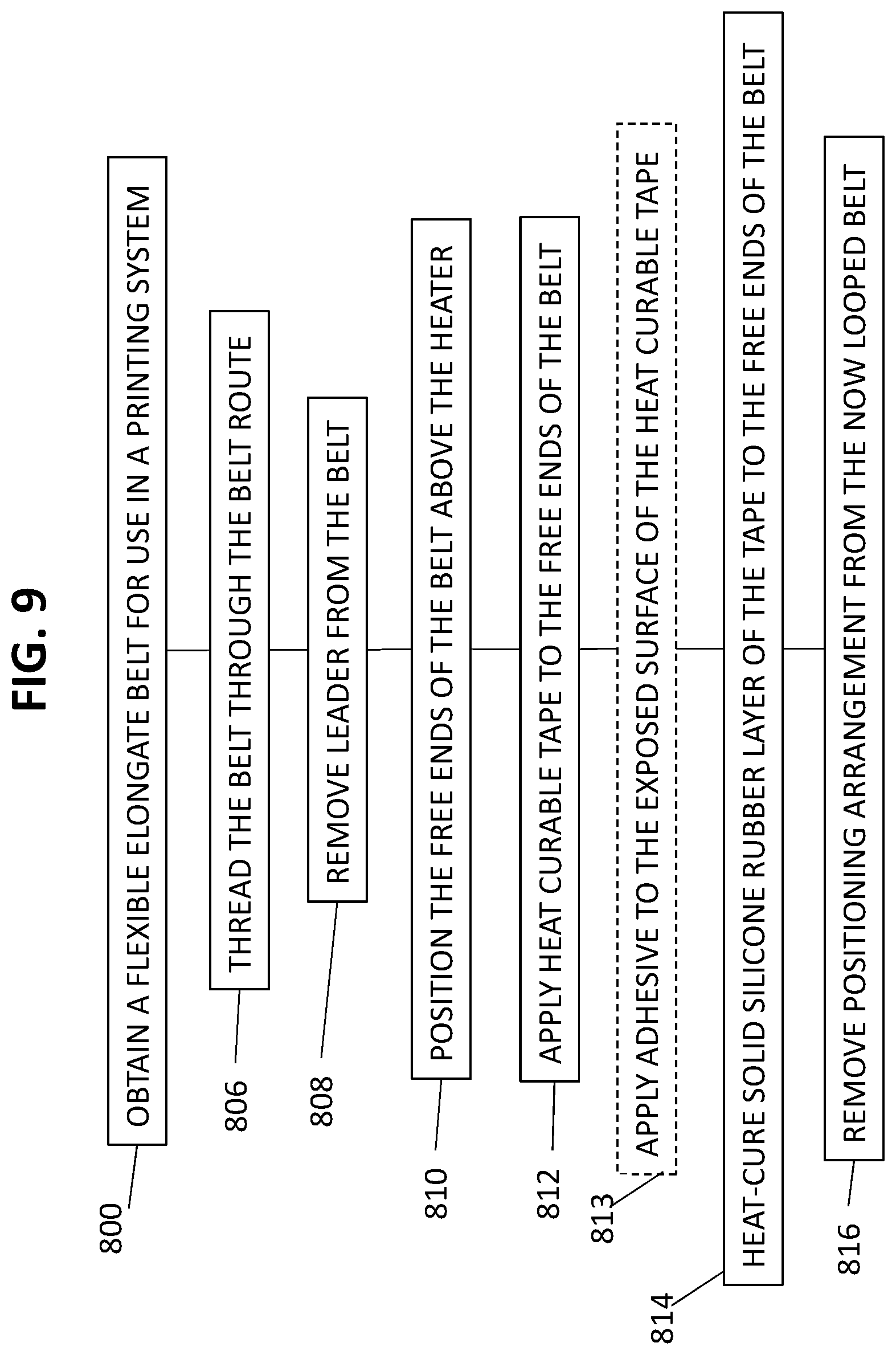
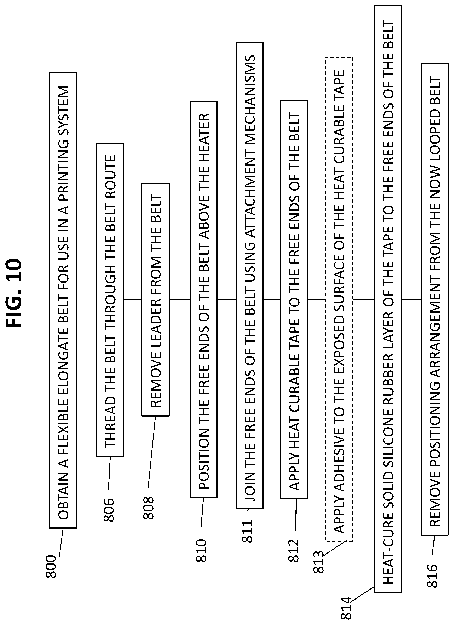
68. A method of forming an endless belt from a flexible belt having first and second free ends the method comprising: when the flexible belt is threaded through a belt route of a printing system such that the first and second free ends are positioned over a heater disposed in the printing system, performing the following: (i) applying a heat-curable tape, comprising a substrate layer and a solid silicone rubber layer disposed thereon, or respective portions thereof, over the first and second free ends of the flexible belt; and (ii) heat-curing said solid silicone rubber layer of said heat-curable tape to the first and second free ends of the flexible belt, so as to form a seam connecting the first and second free ends thereby converting the flexible belt into an endless belt.
69. The method of claim 68, said flexible belt including lateral formations along sides thereof, said method further comprising threading said flexible belt through the belt route by engaging said formations with lateral tracks of the printing system for guiding said flexible belt along the printing system.
70. The method of claim 68 or claim 69, further comprising providing said heater beneath said intermediate transfer member, and wherein said heat-curing comprises operating said heater to provide heat sufficient for said heat-curing.
71. The method of any one of claims 68 to 70, further comprising, following said applying said heat-curable tape and prior to said heat-curing, applying an adhesive onto an exposed surface of said heat-curable tape.
72. A method of forming an endless belt from a flexible belt having first and second free ends the method comprising: providing a heat-curable tape, comprising a substrate layer and a solid silicone rubber layer disposed thereon, or respective portions thereof; providing a heater adapted to provide heat sufficient for heat-curing said solid silicone rubber layer; threading the flexible belt through a belt route of a printing system to position the first and second free ends over said heater; applying said heat-curable tape over the first and second free ends of the flexible belt; and using said heater, heat-curing said solid silicone rubber layer of said heat-curable tape to the first and second free ends of the flexible belt, so as to form a seam connecting the first and second free ends thereby forming an endless belt from the flexible belt.
73. The method of claim 72, further comprising, following said applying said heat-curable tape and prior to said heat-curing, applying an adhesive onto an exposed surface of said heat-curable tape.
74. The method of any one of claims 68 to 73, wherein, following said heat-curing of said solid silicone rubber layer of said heat curable tape, the following properties are true: said tape has a tensile strength of at least 8 MPa; said tape has a shore A hardness of at least 45; and a strength of said heat curable tape is directly proportional to a heat quantity applied to said solid silicone rubber layer during curing of said tape.
75. The method of any one of claims 68 to 73, wherein, following said heat-curing, at least one of the following properties is true: said tape has a tensile strength of at least 8 MPa; said tape has a shore A hardness of at least 45; said tape has a shore A hardness in the range of 45 to 80; a strength of said heat curable tape is directly proportional to a heat quantity applied to said solid silicone rubber layer during curing of said tape; a 20 mm segment of said endless belt including said tape is capable of resisting a load of at least 200N, at least 220N, or at least 250N, at room temperature; and a 20 mm segment of said endless belt including said tape is incapable of resisting a load greater than 350N, greater than 380N, or greater than 400N, at room temperature.
76. The method of any one of claims 68 to 75, wherein said heater includes a heating surface having a width greater than a width of said heat-curable tape.
77. The method of any one of claims 68 to 76, wherein said heat-curing comprises activating the heater to provide a temperature of at least 130 C for a duration of at most 1 minute, at most 3 minutes, at most 5 minutes, at most 10 minutes, at most 15 minutes, or at most 20 minutes uniformly across said heat-curable tape.
78. The method of claim 76 or claim 77, wherein said heat-curing comprises activating the heater to provide a greater heat density at ends of said heating surface than at a center of said heating surface.
79. The method of any one of claims 76 to 78, wherein said heat-curing comprises activating said heater to provide a first operative temperature at a center of a heating surface of the heater, and to provide a second operative temperature at ends of the heating surface of the heater.
80. The method of claim 79, wherein said activating said heater comprises activating said heater to provide said first and said second operative temperatures for a duration of at most 1 minute, at most 3 minutes, at most 5 minutes, at most 10 minutes, at most 15 minutes, or at most 20 minutes, thereby to heat-cure said solid silicone rubber of said heat-curable tape.
81. The method of any one of claims 79 to 80, wherein said activating said heater comprises activating said heater such that a temperature of a heating surface of said heater reaches said first and second operative temperatures within a duration of at most 1 minute, at most 3 minutes, at most 5 minutes, or at most 10 minutes.
82. The method of any one of claims 69 to 81, further comprising: prior to said threading of said flexible belt through said belt route, attaching a positioning arrangement to said first and second free ends; and prior to said applying said heat-curable tape, using said positioning arrangement, positioning said first and second free ends in a fixed position relative to the heater.
83. The method of claim 82, further comprising, following said heat-curing, removing said positioning arrangement from said flexible belt.
84. The method of any one of claims 82 to 83, wherein said positioning arrangement includes at least one magnetic element, and wherein said positioning comprises magnetically engaging said at least one magnetic element to at least one corresponding magnetic element of the heater.
85. The method of any one of claims 69 to 84, further comprising: prior to said threading of said flexible belt through said belt route, forming a rebate at each of said first and second free ends of said flexible belt; and following threading of said flexible belt through said belt route, positioning said rebates adjacent one another to form a channel, wherein said applying said heat-curable tape comprises accommodating said heat-curable tape in said channel.
86. The method of claim 85, wherein said forming a rebate comprises forming a rebate having a depth in the range of 140 .mu.m to 250 .mu.m.
87. The method of any one of claims 68 to 86, further comprising, following said heat-curing, operating said endless belt in said printing system at an operational temperature of 150 C for a duration of at least two weeks without failure of said seam.
88. The method of any one of claims 72 to 87, the flexible belt comprising a plurality of lateral formations along at least a portion of each lateral edge, wherein at least one of the lateral formations on each lateral edge at each one of the free ends of the flexible belt includes an anchoring structure adapted for attachment to an attachment mechanism, the method additionally comprising the step of: connecting at least one said attachment mechanism to anchoring structures associated with the lateral formations of each of the respective first and second free ends of each lateral side of the belt, so as to attach the first and second free ends of the belt to each other.
89. The method of any one of claim 88, wherein each said anchoring structure comprises a crimping-pin-hole extending through said lateral formation in a direction orthogonal to a surface of the belt and each said attachment mechanism comprises a crimping pin including a pair of upright members, wherein said connecting comprises: a. inserting two crimping pins, one crimping pin for each lateral edge of the belt, through respective pairs of crimping-pin-holes in the ultimate lateral formations of each of the respective first and second free ends of the belt, so as to hold the first and second free ends of the belt in proximity to each other, and b. crimping ends of the upright members of each of the crimping pins.
90. A method of printing an image onto a substrate in a printing system including a printing station and an impression station, the method comprising: in the printing system, forming an endless belt according to the method of any one of claims 68 to 89; ink-jet printing an image onto a surface of said endless belt; rotating said endless belt to move said image from the printing station to the impression station; and transferring said image from said surface of said endless belt onto the substrate.
91. A printing system comprising: an intermediate transfer member (ITM) comprising an endless belt, said endless belt comprising a flexible elongate belt having first and second ends, said first and second ends connected by a seam; a heater disposed beneath said intermediate transfer member and adapted to provide heat sufficient for attaching said seam to said first and second ends; an image forming station at which droplets of an ink are applied to an outer surface of said intermediate transfer member to form an ink image; a drying station for drying the ink image to leave an ink residue film; and an impression station at which the residue film is transferred to a sheet or web substrate sheet.
92. The printing system of claim 91, wherein said seam includes a heat curable adhesive and wherein said heater is adapted to provide heat sufficient for heat-curing the heat-curable adhesive of said seam.
93. The printing system of claim 91 or claim 92, said heater including a heating surface having a width greater than a width of said seam.
94. The printing system of any one of claims 91 to 93, wherein said heater forms part of a belt support system of the printing system, and is mounted adjacent rollers adapted to guide said endless belt during operation of the printing system.
95. The printing system of any one of claims 93 to 94, wherein the heater is designed such that a greater heat density is provided at ends of said heating surface than at a center of said heating surface.
96. The printing system of any one of claims 93 to 95, wherein said heater includes a plurality of heating elements, said heating elements being unevenly distributed across said heating surface, such that a greater heat density is provided at ends of said heating surface than at a center of said heating surface.
97. The printing system of any one of claims 95 to 96, wherein said heater is adapted, during operation thereof, to provide a first operative temperature at said center of said heating surface, and to provide a second operative temperature at said ends of said heating surface.
98. The printing system of claim 97, wherein, during operation of said heater, when said first and second ends of said flexible elongate belt are disposed over said heating surface, and said seam is disposed over said first and second ends, said heater is adapted to provide said first and said second operative temperatures for a duration of at most 1 minute, at most 3 minutes, at most 5 minutes, at most 10 minutes, at most 15 minutes, or at most 20 minutes, thereby to heat-cure said seam.
99. The printing system of any one of claims 97 to 98, wherein said heater is adapted to reach said first and second operative temperatures within a duration of at most 1 minute, at most 3 minutes, at most 5 minutes, or at most 10 minutes.
100. The printing system of any one of claims 93 to 99, wherein said heater is adapted, during operation thereof when said first and second ends of said flexible elongate belt are disposed over said heating surface, and said seam is disposed over said first and second ends, to provide a uniform temperature across said seam.
101. The printing system of any one of claims 91 to 100, wherein said flexible belt has at least one of the following properties: a length within a range of 1 to 20 meters, 5 to 20 meters, 5 to 15 meters, 5 to 12 meters, or 7 to 12 meters; a width with a range of 0.1 to 2.0 meters, 0.3 to 2.0 meters, 0.5 to 2.0 meters, 0.75 to 2.0 meters, 0.75 to 1.5 meters, or 0.75 to 1.25 meters; and a thickness within a range of 50 to 3000 .mu.m, 100 to 3000 .mu.m, 200 to 3000 .mu.m, 200 to 1500 .mu.m, 300 to 1000 .mu.m, 300 to 800 .mu.m, 300 to 700 .mu.m, or 100 to 600 .mu.m.
102. The printing system of any one of claims 91 to 101, wherein said intermediate transfer member is used for indirect ink-jet printing in the printing system at an operational temperature in the range of 130 C to 170 C for a duration of at least two weeks without failure of said seam.
103. The printing system of any one of claims 91 to 102, wherein said flexible elongate belt has a positioning arrangement removably attached to said first and second ends, said positioning arrangement adapted for positioning said first and second ends of said flexible belt over said heater during heat-curing of said heat-curable adhesive.
104. The printing system of claim 103, wherein said positioning arrangement includes at least one magnetic element, and said heater includes at least one corresponding magnetic element adapted to magnetically attract said at least one magnetic element of said positioning arrangement during said heat-curing of said heat-curable adhesive.
105. The printing system of claim 104, wherein said at least one magnetic element comprises a magnetic metal strip removably attached to each of said first and second ends of said flexible elongate belt.
106. The printing system of any one of claims 91 to 105, wherein: (i) the flexible elongate belt includes a plurality of lateral formations along at least a portion of each lateral edge, (ii) at least one of the lateral formations on each lateral edge at each one of the free ends of the flexible belt including an anchoring structure; and (iii) at least two attachment mechanisms each engaging at least two said anchoring structures associated with laterally extending formations at each one of the opposing free ends of a lateral edge of the belt and attaching the laterally extending formations associated with said at least two said anchoring structures to each other, thereby attaching said opposing free ends on each lateral edge of the flexible belt.
107. The printing system of claim 106, wherein said anchoring structure comprises a crimping-pin-hole extending through said lateral formation in a direction orthogonal to a surface of the belt and each said attachment mechanism comprises a crimping pin having a diameter less than or equal to the diameters of said crimping-pin holes, simultaneously engaging two said crimping-pin-holes, one in each of said free ends of one of the lateral edges of the belt.
108. A method of forming said endless belt of the printing system of any one of claims 91 to 107, the method comprising: threading said flexible elongate belt through a belt route of said printing system, such that said first and second ends of said flexible elongate belt are placed adjacent one another over said heater; applying said seam over the first and second free ends of the flexible belt; and using said heater, attaching said seam to the first and second free ends of the flexible belt, so as to connect the first and second free ends thereby converting the flexible belt into an endless belt.
109. A method of forming said endless belt of the printing system of any one of claims 103 to 107, the method comprising: attaching said positioning arrangement to said first and second free ends of said flexible belt; threading said flexible elongate belt through a belt route of said printing system, such that said first and second ends of said flexible elongate belt are placed adjacent one another over said heater; using said positioning arrangement, positioning said first and second free ends in a fixed position relative to the heater; applying said seam over the first and second free ends of the flexible belt; and using said heater, attaching said seam to the first and second free ends of the flexible belt, so as to connect the first and second free ends thereby converting the flexible belt into an endless belt.
110. The method of claim 109, further comprising, following said attaching, removing said positioning arrangement from said flexible belt.
111. The method of any one of claims 108 to 110, further comprising: prior to threading of said flexible belt through said belt route, forming a rebate at each of said first and second free ends of said flexible belt; and following threading of said flexible belt through said belt route, positioning said rebates adjacent one another to form a channel, wherein said applying said seam comprises placing said seam in said channel.
112. The method of claim 111, wherein said forming a rebate comprises forming a rebate having a depth in the range of 140 .mu.m to 250 .mu.m.
113. The method of any one of claims 108 to 112, wherein said attaching comprises operating said heater to provide a greater heat density at ends of said heater than at a center of said heater.
114. The method of any one of claims 108 to 113, wherein said attaching comprises operating the heater to provide a first operative temperature at a center of said heater, and to provide a second operative temperature at ends of said heater.
115. The method of any one of claims 108 to 114, the flexible belt comprising a plurality of lateral formations along at least a portion of each lateral edge thereof, wherein at least one of the lateral formations on each lateral edge at each one of the free ends of the flexible belt includes an anchoring structure for a attachment mechanism, the method additionally comprising the step of: connecting at least one said attachment mechanism to anchoring structures associated with the lateral formations of each of the respective first and second free ends of each lateral side of the belt, so as to attach the first and second free ends of the belt to each other.
116. The method of any one of claim 115, wherein each said anchoring structure comprises a crimping-pin-hole extending through said lateral formation in a direction orthogonal to a surface of the belt and each said attachment mechanism comprises a crimping pin including a pair of upright members, wherein said connecting comprises: a. inserting two crimping pins, one crimping pin for each lateral edge of the belt, through respective pairs of crimping-pin-holes in the ultimate lateral formations of each of the respective first and second free ends of the belt, so as to hold the first and second free ends of the belt in proximity to each other, and b. crimping ends of the upright members of each of the crimping pins.
117. A method of printing an image onto a substrate in a printing system including a printing station and an impression station, the method comprising: in the printing system, forming an endless belt according to the method of any one of claims 108 to 116; ink-jet printing an image onto a surface of said endless belt; rotating said endless belt to move said image from the printing station to the impression station; and transferring said image from said surface of said endless belt onto the substrate.
118. A kit for installing an endless belt in a printing system, the kit comprising: a heat-curable tape, comprising a substrate layer and a solid silicone rubber layer disposed thereon; and an adhesive; wherein said heat-curable tape is adapted to be applied onto first and second free ends of a flexible belt, and to be heated so as to heat-cure said solid silicone rubber layer of said tape to the first and second free ends of the flexible belt, so as to form a seam connecting the first and second free ends thereby converting the flexible belt into the endless belt, and wherein said adhesive is adapted to fill and seal gaps between said heat-curable tape and at least a portion of the flexible belt when said heat-curable tape is cured.
119. The kit of claim 118, wherein said adhesive is adapted to be applied onto and around an exposed surface of said heat-curable tape, when said heat-curable tape is applied onto the first and second free ends of the flexible belt.
120. The kit of claim 118 or claim 119, wherein said adhesive comprises a two component adhesive, the two components adapted to be mixed prior to application thereof onto said heat-curable tape.
121. The kit of any one of claims 118 to 120, wherein, following heat-curing of said solid silicone rubber layer of said heat curable tape, the following properties are true: said tape has a tensile strength of at least 8 MPa; said tape has a shore A hardness of at least 45; and a strength of said heat curable tape is directly proportional to a heat quantity applied to said solid silicone rubber layer during curing of said tape.
122. The kit of any one of claims 118 to 120, wherein, following heat-curing of said solid silicone rubber layer of said tape, at least one of the following is true: said tape has a tensile strength of at least 8 MPa; said tape has a shore A hardness of at least 45; said tape has a shore A hardness in the range of 45 to 80; a strength of said heat curable tape is directly proportional to a heat quantity applied to said solid silicone rubber layer during curing of said tape; a 20 mm segment of said endless belt, including said heat-cured tape, is capable of resisting a load of at least 200N, at least 220N, or at least 250N, at room temperature; and a 20 mm segment of said endless belt, including said heat-cured tape, is incapable of resisting a load greater than 350N, greater than 380N, or greater than 400N, at room temperature.
123. The kit of any one of claims 118 to 122, wherein said solid silicone rubber has a shelf life of at least one month, at least six months, at least one year.
124. The kit of any one of claims 118 to 123, wherein a pot life of said heat curable tape is at least one of: equal to a shelf life of said solid silicone rubber; and at least one month, at least six months, or at least one year.
125. The kit of any one of claims 118 to 124, wherein said solid silicone rubber comprises a thermosetting polymer.
126. The kit of any one of claims 118 to 125, wherein said solid silicone rubber has a density in the range of 1.1 to 1.2 g/cm{circumflex over ( )}3, or a density of 1.15 g/cm{circumflex over ( )}3.
127. The kit of any one of claims 118 to 126, wherein said substrate layer includes a fiberglass layer.
128. The kit of claim 127, wherein said substrate layer further includes a silicone coating layer, connected to said fiberglass layer.
129. The kit of claim 128, wherein said silicone coating layer has a shore A hardness in the range of 75 to 80.
130. The kit of any one of claims 118 to 129, wherein said substrate layer has a thickness in the range of 110 .mu.m to 170 .mu.m.
131. The kit of any one of claims 118 to 130, wherein said solid silicone rubber layer has a thickness in the range of 20 mm to 120 .mu.m.
132. The kit of any one of claims 118 to 131, wherein a ratio between a thickness of said solid silicone rubber layer and a thickness of said substrate layer is in the range of 0.10 to 0.75.
133. The kit of any one of claims 118 to 132, wherein said curable tape has a thickness in the range of 180 .mu.m to 270 .mu.m.
134. The kit of any one of claims 118 to 133, further comprising said flexible belt having said first and second free ends, said flexible belt configured to be guided along the printing system.
135. The kit of claim 134, wherein said flexible belt has at least one of the following properties: a length within a range of 1 to 20 meters, 5 to 20 meters, 5 to 15 meters, 5 to 12 meters, or 7 to 12 meters; a width within a range of 0.1 to 2.0 meters, 0.3 to 2.0 meters, 0.5 to 2.0 meters, 0.75 to 2.0 meters, 0.75 to 1.5 meters, or 0.75-1.25 meters; and a thickness within a range of 50 to 3000 .mu.m, 100 to 3000 .mu.m, 200 to 3000 .mu.m, 200 to 1500 .mu.m, 300 to 1000 .mu.m, 300 to 800 .mu.m, 300 to 700 .mu.m, or 100 to 600 .mu.m.
136. The kit of any one of claims 134 to 135, wherein a ratio between a thickness of said tape and a thickness of said belt is in the range of 0.15 to 11.15.
137. The kit of any one of claims 134 to 136, wherein a length of said heat curable tape is greater than a width of said flexible belt.
138. The kit of any one of claims 134 to 137, wherein a ratio between a width of said tape and a length of said belt is in the range of 0.01 to 0.03.
139. The kit of any one of claims 134 to 138, further comprising a heater adapted to be disposed beneath said heat curable tape when said heat curable tape is applied to said first and second ends of said flexible belt, and adapted to provide heat sufficient for heat-curing said solid silicone rubber of said heat-curable tape thereby to heat-cure said heat curable tape to form said endless belt.
140. The kit of claim 139, wherein said heater includes a heating surface having a width greater than a width of said heat-cured tape.
141. The kit of claim 140, wherein the heater is designed such that a greater heat density is provided at ends of said heating surface than at a center of said heating surface.
142. The kit of claim 140, wherein the heater includes a plurality of heating elements, said heating elements being unevenly distributed across said heating surface, such that a greater heat density is provided at ends of said heating surface than at a center of said heating surface.
143. The kit of any one of claims 139 to 142, wherein said heater is adapted, during operation thereof, to provide a first operative temperature at said center of said heating surface, and to provide a second operative temperature at said ends of said heating surface.
144. The kit of any one of claims 139 to 143, wherein said heater is adapted, during operation thereof when said first and second ends of said flexible elongate belt are disposed over said heating surface, and said heat-curable tape is disposed over said first and second ends, to provide a uniform temperature across said heat-curable tape.
145. The kit of any one of claims 143 to 144, wherein, during operation of said heater, when said first and second ends of said flexible elongate belt are disposed over said heating surface, and said heat-curable tape is disposed over said first and second ends, said heater is adapted to provide said first and said second operative temperatures for a duration of at most 1 minute, at most 3 minutes, at most 5 minutes, at most 10 minutes, at most 15 minutes, or at most 20 minutes, thereby to heat-cure said solid silicone rubber of said heat-curable tape.
146. The kit of any one of claims 143 to 145, wherein said heater is adapted to reach said first and second operative temperatures within a duration of at most 1 minute, at most 3 minutes, at most 5 minutes, or at most 10 minutes.
147. The kit of any one of claims 139 to 146, wherein said flexible elongate belt has a positioning arrangement removably attached to said first and second ends, said positioning arrangement adapted for positioning said first and second ends of said belt over said heating surface of said heater during heat-curing of said heat-curable tape.
148. The kit of claim 147, wherein said positioning arrangement includes at least one magnetic element, and said heater includes at least one corresponding magnetic element adapted to magnetically attract said at least one magnetic element of said positioning arrangement during said heat-curing of said heat-curable tape.
149. The kit of claim 148, wherein said at least one magnetic element comprises a magnetic metal strip removably attached to each of said first and second ends of said flexible elongate belt.
150. The kit of any one of claims 134 to 149, wherein said flexible belt includes a rebate at each of said first and second ends, wherein when said rebates are positioned adjacent one another a channel is formed, said channel sized and adapted to accommodate said heat curable tape therein.
151. The kit of claim 150, wherein each said rebate has a depth in the range of 140 .mu.m to 250 .mu.m.
152. The kit of any one of claims 134 to 151, wherein: (i) the flexible belt includes a plurality of lateral formations along at least a portion of each lateral edge, and (ii) at least one of the lateral formations on each lateral edge at each one of the free ends of the flexible belt includes an anchoring structure adapted for attachment to an attachment mechanism, which attachment mechanism is adapted for attaching ones of said laterally extending formations at opposing free ends of each lateral edge of the flexible belt.
153. The kit of claim 152, additionally including at least two attachment mechanisms each adapted to engage at least two said anchoring structures at opposing free ends of each lateral edge of said belt and to attach the laterally extending formations associated with said anchoring structures engaged by said attachment mechanism thereby to attach said opposing free ends of each lateral edge of the flexible belt.
154. The kit of claim 153, wherein each said anchoring structure comprises a crimping-pin-hole extending through a corresponding said lateral formation in a direction orthogonal to a surface of the belt and each said attachment mechanism comprises a crimping pin having a diameter less than or equal to the diameter of a said crimping-pin hole, and adapted to simultaneously engage two said crimping-pin-holes, one in each of said opposing free ends of one of the lateral edges of the belt.
155. A kit for installing an endless belt in a printing system, the kit comprising: a flexible belt having first and second free ends configured to be guided along the printing system, the flexible belt includes a plurality of lateral formations along at least a portion of each lateral edge thereof, wherein at least one of the lateral formations on each lateral edge at each one of the free ends of the flexible belt includes an anchoring structure adapted for attachment to an attachment mechanism, and at least two attachment mechanisms each adapted to engage at least two said anchoring structures at opposing free ends of each lateral edge of said belt and to attach the laterally extending formations associated with said anchoring structures engaged by said attachment mechanism thereby to attach said opposing free ends of each lateral edge of the flexible belt.
156. The kit of claim 155, wherein: each said anchoring structure comprises a crimping-pin-hole extending through a corresponding said lateral formation in a direction orthogonal to a surface of the belt; and each said attachment mechanism comprises a crimping pin having a diameter less than or equal to the diameter of a said crimping-pin hole, and adapted to simultaneously engage two said crimping-pin-holes, one in each of said opposing free ends of one of the lateral edges of the belt.
157. The kit of claim 155 or claim 156, wherein said flexible belt has at least one of the following properties: a length within a range of 1 to 20 meters, 5 to 20 meters, 5 to 15 meters, 5 to 12 meters, or 7 to 12 meters; a width within a range of 0.1 to 2.0 meters, 0.3 to 2.0 meters, 0.5 to 2.0 meters, 0.75 to 2.0 meters, 0.75 to 1.5 meters, or 0.75-1.25 meters; and a thickness within a range of 50 to 3000 .mu.m, 100 to 3000 .mu.m, 200 to 3000 .mu.m, 200 to 1500 .mu.m, 300 to 1000 .mu.m, 300 to 800 .mu.m, 300 to 700 .mu.m, or 100 to 600 .mu.m.
Description
CROSS REFERENCE TO RELATED APPLICATIONS
[0001] This patent application claims priority from U.S. Provisional Application No. 62/532,400, filed on Jul. 14, 2017, from U.S. Provisional Application No. 62/641,296, filed on Mar. 10, 2018, and from U.S. Provisional Application No. 62/679,839, filed on Jun. 3, 2018, all of which are entitled "INTERMEDIATE TRANSFER MEMBER". U.S. Provisional Application Nos. 62/532,400, 62/641,296, and 62/679,839 are all incorporated by reference as if fully set forth herein.
FIELD AND BACKGROUND OF THE INVENTION
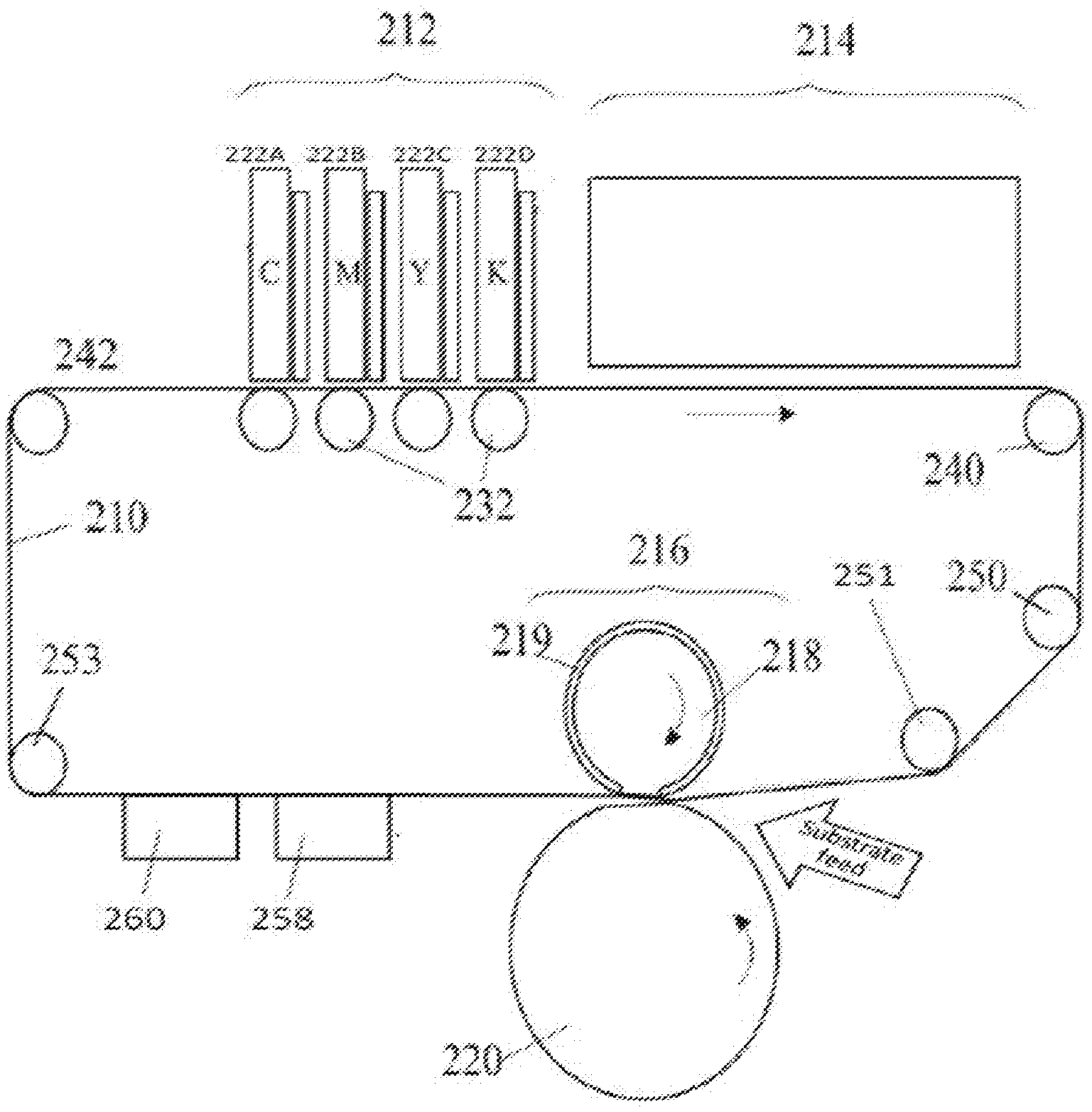
[0002] The present disclosure relates to an intermediate transfer member (ITM) used in a printing system in which liquid ink droplets are deposited at an image forming station onto a movable intermediate transfer member and transferred at an impression station from the intermediate transfer member onto a printing substrate. Specifically, this disclosure pertains to an intermediate transfer member formed as a flexible elongate belt, the ends of which are connected to each other by means of a heat-curable tape to form an endless blanket or belt. The disclosure further pertains to systems and devices for installing the heat-curable tape and the intermediate transfer member in corresponding printing systems.
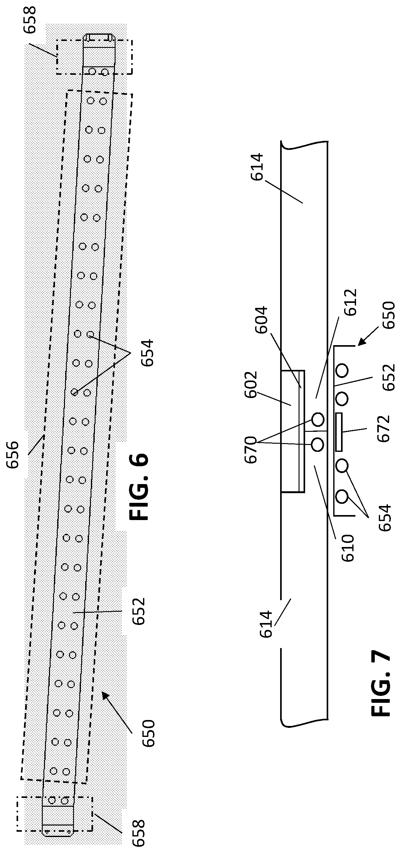
[0003] The intermediate transfer member is formed of an elongate flexible belt, which is threaded through the printing system, and the free ends of the belt are connected to one another to form the endless belt of the intermediate transfer member. The portion or element used to connect the free ends of the belt is referred to herein as a seam element.
SUMMARY OF THE INVENTION
[0004] The invention, in some embodiments, relates to a heat-curable tape for connecting ends of an elongate belt to form an intermediate transfer member suitable for use with indirect printing systems.
[0005] The invention, in some embodiments, relates to a kit for installing an intermediate transfer member in a printing system, the kit including an elongate belt and a heat-curable tape.
[0006] The invention, in some embodiments, relates to a printing system including an intermediate transfer member formed of an elongate belt and a heat-curable tape.
[0007] The invention, in some embodiments, relates to a kit for installing an intermediate transfer member in a printing system, the kit including a heat-curable tape and an adhesive.
[0008] The invention, in some embodiments, relates to a method for installing an intermediate transfer member in a printing system, the intermediate transfer member including an elongate belt and a heat-curable tape joining ends of the elongate belt at a seam.
[0009] The invention, in some embodiments, relates to a heater for heat-curing a heat-curable tape onto free ends of an elongate belt so as to form an intermediate transfer member of a printing system, to printing systems including such a heater, and to methods of using such a heater.
[0010] The invention, in some embodiments, relates to a kit for installing an endless belt in a printing system, the kit including an elongate belt and attachment mechanisms.
[0011] As is discussed in greater detail hereinbelow, a heat-curable tape according to the present invention includes a substrate layer and a solid silicone rubber layer disposed on the substrate layer. The heat curable tape is applied onto first and second free ends of a flexible belt guided through a suitable route of a printing system, and is then heated so as to heat-cure the solid silicone rubber to the free ends of the flexible belt, thereby to convert the flexible belt into an endless belt of an intermediate transfer member. Heat may be applied to the heat curable tape by a heater, forming part of the printing system in which the intermediate transfer member is being installed, the heater typically disposed beneath the free ends of the belt during heating of the heat-curable tape.
[0012] There is thus provided, in accordance with an embodiment of a first aspect of the invention, a kit for installing an endless belt in a printing system, the kit including: [0013] a flexible belt having first and second free ends configured to be guided along the printing system; [0014] a heat-curable tape, including a substrate layer and a solid silicone rubber layer disposed thereon,
[0015] wherein the heat-curable tape is adapted to be applied onto the first and second free ends of the flexible belt, and to be heated so as to heat-cure the solid silicone rubber layer of the tape to the first and second free ends of the flexible belt, so as to form a seam connecting the first and second free ends thereby converting the flexible belt into an endless belt.
[0016] In some embodiments of the first aspect of the invention, the flexible belt has a length within a range of 1 to 20 meters.
[0017] In some embodiments of the first aspect of the invention, the flexible belt has a length within a range of 5 to 20 meters.
[0018] In some embodiments of the first aspect of the invention, the flexible belt has a length within a range of 5 to 15 meters.
[0019] In some embodiments of the first aspect of the invention, the flexible belt has a length within a range of 5 to 12 meters.
[0020] In some embodiments of the first aspect of the invention, the flexible belt has a length within a range of 7 to 12 meters.
[0021] In some embodiments of the first aspect of the invention, the flexible belt has a width within a range of 0.1 to 2.0 meters.
[0022] In some embodiments of the first aspect of the invention, the flexible belt has a width within a range of 0.3 to 2.0 meters.
[0023] In some embodiments of the first aspect of the invention, the flexible belt has a width within a range of 0.5 to 2.0 meters.
[0024] In some embodiments of the first aspect of the invention, the flexible belt has a width within a range of 0.75 to 2.0 meters.
[0025] In some embodiments of the first aspect of the invention, the flexible belt has a width within a range of 0.75 to 1.5 meters.
[0026] In some embodiments of the first aspect of the invention, the flexible belt has a width within a range of 0.75 to 1.25 meters.
[0027] In some embodiments of the first aspect of the invention, the flexible belt has a thickness within a range of 50 to 3000 .mu.m.
[0028] In some embodiments of the first aspect of the invention, the flexible belt has a thickness within a range of 100 to 3000 .mu.m.
[0029] In some embodiments of the first aspect of the invention, the flexible belt has a thickness within a range of 200 to 3000 .mu.m.
[0030] In some embodiments of the first aspect of the invention, the flexible belt has a thickness within a range of 200 to 1500 .mu.m.
[0031] In some embodiments of the first aspect of the invention, the flexible belt has a thickness within a range of 300 to 1000 .mu.m.
[0032] In some embodiments of the first aspect of the invention, the flexible belt has a thickness within a range of 300 to 800 .mu.m.
[0033] In some embodiments of the first aspect of the invention, the flexible belt has a thickness within a range of 300 to 700 .mu.m.
[0034] In some embodiments of the first aspect of the invention, the flexible belt has a thickness within a range of 100 to 600 .mu.m.
[0035] In some embodiments of the first aspect of the invention, following heat-curing of the solid silicone rubber layer, the tape has a tensile strength of at least 8 MPa.
[0036] In some embodiments of the first aspect of the invention, following heat-curing of the solid silicone rubber layer, the tape has a shore A hardness of at least 45.
[0037] In some embodiments of the first aspect of the invention, following heat-curing of the solid silicone rubber layer, the tape has a shore A hardness not greater than 80.
[0038] In some embodiments of the first aspect of the invention, following heat-curing of the solid silicone rubber layer of the heat curable tape, the following properties are true:
[0039] the tape has a tensile strength of at least 8 MPa;
[0040] the tape has a shore A hardness of at least 45; and
[0041] a strength of the heat curable tape is directly proportional to a heat quantity applied to the solid silicone rubber layer during curing of the tape.
[0042] In some embodiments of the first aspect of the invention, following heat-curing of the solid silicone rubber layer, the solid silicone rubber layer has a shore A hardness in the range of 55 to 65.
[0043] In some embodiments of the first aspect of the invention, the solid silicone rubber includes a thermosetting polymer.
[0044] In some embodiments of the first aspect of the invention, the thermosetting polymer includes a platinum catalyzed addition-curing solid silicone rubber.
[0045] In some embodiments of the first aspect of the invention, the solid silicone rubber has a density in the range of 1.1 to 1.2 g/cm{circumflex over ( )}3.
[0046] In some embodiments of the first aspect of the invention, the solid silicone rubber has a density of 1.15 g/cm{circumflex over ( )}3.
[0047] In some embodiments of the first aspect of the invention, the solid silicone rubber has a shelf life of at least one month.
[0048] In some embodiments of the first aspect of the invention, the solid silicone rubber has a shelf life of at least six months.
[0049] In some embodiments of the first aspect of the invention, the solid silicone rubber has a shelf life of at least one year.
[0050] In some embodiments of the first aspect of the invention, a pot life of the heat curable tape is equal to a shelf life of the solid silicone rubber.
[0051] In some embodiments of the first aspect of the invention, a pot life of the heat curable tape is at least one month.
[0052] In some embodiments of the first aspect of the invention, a pot life of the heat curable tape is at least six months.
[0053] In some embodiments of the first aspect of the invention, a pot life of the heat curable tape is at least one year.
[0054] In some embodiments of the first aspect of the invention, the substrate layer includes a fiberglass layer.
[0055] In some embodiments of the first aspect of the invention, the substrate layer further includes a silicone coating layer, connected to the fiberglass layer.
[0056] In some embodiments of the first aspect of the invention, the silicone coating layer has a shore A hardness in the range of 75 to 80.
[0057] In some embodiments of the first aspect of the invention, the substrate layer has a thickness in the range of 110 .mu.m to 170 .mu.m.
[0058] In some embodiments of the first aspect of the invention, the substrate layer has a thickness of 160 .mu.m.
[0059] In some embodiments of the first aspect of the invention, the solid silicone rubber layer has a thickness in the range of 20 .mu.m to 120 .mu.m.
[0060] In some embodiments of the first aspect of the invention, a ratio between a thickness of the solid silicone rubber layer and a thickness of the substrate layer is in the range of 0.10 to 0.75.
[0061] In some embodiments of the first aspect of the invention, the curable tape has a thickness in the range of 180 .mu.m to 270 .mu.m.
[0062] In some embodiments of the first aspect of the invention, a ratio between a thickness of the tape and a thickness of the belt is in the range of 0.15 to 11.15.
[0063] In some embodiments of the first aspect of the invention, a length of the heat curable tape is greater than a width of the flexible belt.
[0064] In some embodiments of the first aspect of the invention, a length of the heat curable tape is in the range of 1200 mm to 1300 mm.
[0065] In some embodiments of the first aspect of the invention, a width of the heat curable tape is in the range of 20 mm to 30 mm.
[0066] In some embodiments of the first aspect of the invention, a ratio between a width of the tape and a length of the belt is in the range of 0.01 to 0.03.
[0067] In some embodiments of the first aspect of the invention, the kit further includes a heater adapted to be disposed beneath the heat curable tape when the heat curable tape is applied to the first and second ends of the flexible belt, and adapted to provide heat sufficient for heat-curing the solid silicone rubber of the heat-curable tape thereby to heat-cure the heat curable tape to form the endless belt.
[0068] In some embodiments of the first aspect of the invention, the heater includes a heating surface having a width greater than a width of the heat-cured tape. In some embodiments of the first aspect of the invention, the heater is designed such that a greater heat density is provided at ends of the heating surface than at a center of the heating surface.
[0069] In some embodiments of the first aspect of the invention, the heater includes a plurality of heating elements, the heating elements being unevenly distributed across the heating surface, such that a greater heat density is provided at ends of the heating surface than at a center of the heating surface.
[0070] In some embodiments of the first aspect of the invention, the plurality of heating elements are printed on ceramic plates.
[0071] In some embodiments of the first aspect of the invention, the plurality of heating elements are printed on filaments.
[0072] In some embodiments of the first aspect of the invention, the plurality of heating elements are printed on mica strips.
[0073] In some embodiments of the first aspect of the invention, the plurality of heating elements are printed on silicon strips.
[0074] In some embodiments of the first aspect of the invention, the heater is adapted, during operation thereof, to provide a first operative temperature at the center of the heating surface, and to provide a second operative temperature at the ends of the heating surface.
[0075] In some embodiments of the first aspect of the invention, the first operative temperature is in the range of 140 C to 180 C.
[0076] In some embodiments of the first aspect of the invention, the second operative temperature is in the range of 180 C to 220 C.
[0077] In some embodiments of the first aspect of the invention, the heater is adapted, during operation thereof when the first and second ends of the flexible elongate belt are disposed over the heating surface, and the heat-curable tape is disposed over the first and second ends, to provide a uniform temperature across the heat-curable tape.
[0078] In some embodiments of the first aspect of the invention, the uniform temperature is in the range of 130 to 180 C.
[0079] In some embodiments of the first aspect of the invention, during operation of the heater, when the first and second ends of the flexible elongate belt are disposed over the heating surface, and the heat-curable tape is disposed over the first and second ends, the heater is adapted to provide the first and the second operative temperatures for a duration of at most 1 minute, thereby to heat-cure the solid silicone rubber of the heat-curable tape.
[0080] In some embodiments of the first aspect of the invention, during operation of the heater, when the first and second ends of the flexible elongate belt are disposed over the heating surface, and the heat-curable tape is disposed over the first and second ends, the heater is adapted to provide the first and the second operative temperatures for a duration of at most 3 minutes, thereby to heat-cure the solid silicone rubber of the heat-curable tape.
[0081] In some embodiments of the first aspect of the invention, during operation of the heater, when the first and second ends of the flexible elongate belt are disposed over the heating surface, and the heat-curable tape is disposed over the first and second ends, the heater is adapted to provide the first and the second operative temperatures for a duration of at most 5 minutes, thereby to heat-cure the solid silicone rubber of the heat-curable tape.
[0082] In some embodiments of the first aspect of the invention, during operation of the heater, when the first and second ends of the flexible elongate belt are disposed over the heating surface, and the heat-curable tape is disposed over the first and second ends, the heater is adapted to provide the first and the second operative temperatures for a duration of at most 10 minutes, thereby to heat-cure the solid silicone rubber of the heat-curable tape.
[0083] In some embodiments of the first aspect of the invention, during operation of the heater, when the first and second ends of the flexible elongate belt are disposed over the heating surface, and the heat-curable tape is disposed over the first and second ends, the heater is adapted to provide the first and the second operative temperatures for a duration of at most 15 minutes, thereby to heat-cure the solid silicone rubber of the heat-curable tape.
[0084] In some embodiments of the first aspect of the invention, during operation of the heater, when the first and second ends of the flexible elongate belt are disposed over the heating surface, and the heat-curable tape is disposed over the first and second ends, the heater is adapted to provide the first and the second operative temperatures for a duration of at most 20 minutes, thereby to heat-cure the solid silicone rubber of the heat-curable tape.
[0085] In some embodiments of the first aspect of the invention, the heater is adapted to reach the first and second operative temperatures within a duration of at most 1 minute.
[0086] In some embodiments of the first aspect of the invention, the heater is adapted to reach the first and second operative temperatures within a duration of at most 3 minutes.
[0087] In some embodiments of the first aspect of the invention, the heater is adapted to reach the first and second operative temperatures within a duration of at most 5 minutes.
[0088] In some embodiments of the first aspect of the invention, the heater is adapted to reach the first and second operative temperatures within a duration of at most 10 minutes.
[0089] In some embodiments of the first aspect of the invention, the heater is formed of a metal selected from the group consisting of aluminum, copper, and brass.
[0090] In some embodiments of the first aspect of the invention, the heating surface has a heat conductivity in the range of 2.35 W/cmK to 40 W/cmK.
[0091] In some embodiments of the first aspect of the invention, the flexible elongate belt has a positioning arrangement removably attached to the first and second ends, the positioning arrangement adapted for positioning the first and second ends of the belt over the heating surface of the heater during heat-curing of the heat-curable tape.
[0092] In some embodiments of the first aspect of the invention, the positioning arrangement includes at least one magnetic element, and the heater includes at least one corresponding magnetic element adapted to magnetically attract the at least one magnetic element of the positioning arrangement during the heat-curing of the heat-curable tape.
[0093] In some embodiments of the first aspect of the invention, the at least one magnetic element includes a magnetic metal strip removably attached to each of the first and second ends of the flexible elongate belt.
[0094] In some embodiments of the first aspect of the invention, the at least one corresponding magnetic element includes at least one samarium cobalt magnet.
[0095] In some embodiments of the first aspect of the invention, the positioning arrangement includes a double sided adhesive.
[0096] In some embodiments of the first aspect of the invention, the positioning arrangement includes at least one fixing pin, and the heater includes at least one corresponding fixing bore, adapted to receive the at least one fixing pin during the heat-curing of the heat curable tape.
[0097] In some embodiments of the first aspect of the invention, the positioning arrangement includes at least one elongate ridge, and the heating surface includes at least one corresponding elongate groove, adapted to receive and engage the at least one elongate ridge during the heat-curing of the heat-curable tape.
[0098] In some embodiments of the first aspect of the invention, the positioning arrangement includes an electrostatic force generating arrangement.
[0099] In some embodiments of the first aspect of the invention, the positioning arrangement is formed of a non-insulating material. In some embodiments of the first aspect of the invention, the positioning arrangement has a heat conductivity of at least 0.8 W/cmK.
[0100] In some embodiments of the first aspect of the invention, the flexible belt includes a rebate at each of the first and second ends, wherein when the rebates are positioned adjacent one another a channel is formed, the channel sized and adapted to accommodate the heat curable tape therein. In some embodiments of the first aspect of the invention, each of the rebates has a depth in the range of 140 .mu.m to 250 .mu.m.
[0101] In some embodiments of the first aspect of the invention, a strength of the heat curable tape, following curing thereof, is directly proportional to a heat quantity applied to the solid silicone rubber layer during curing of the tape.
[0102] In some embodiments of the first aspect of the invention, following heat-curing of the solid silicone rubber layer of the tape, a 20 mm segment of the endless belt, including the heat-cured tape, is capable of resisting a load of at least 200N, at room temperature.
[0103] In some embodiments of the first aspect of the invention, following heat-curing of the solid silicone rubber layer of the tape, a 20 mm segment of the endless belt, including the heat-cured tape, is capable of resisting a load of at least 220N, at room temperature.
[0104] In some embodiments of the first aspect of the invention, following heat-curing of the solid silicone rubber layer of the tape, a 20 mm segment of the endless belt, including the heat-cured tape, is capable of resisting a load of at least 250N, at room temperature.
[0105] In some embodiments of the first aspect of the invention, following heat-curing of the solid silicone rubber layer of the tape, a 20 mm segment of the endless belt, including the heat-cured tape, is incapable of resisting a load greater than 350N at room temperature.
[0106] In some embodiments of the first aspect of the invention, following heat-curing of the solid silicone rubber layer of the tape, a 20 mm segment of the endless belt, including the heat-cured tape, is incapable of resisting a load greater than 380N at room temperature.
[0107] In some embodiments of the first aspect of the invention, following heat-curing of the solid silicone rubber layer of the tape, a 20 mm segment of the endless belt, including the heat-cured tape, is incapable of resisting a load greater than 400N, at room temperature.
[0108] In some embodiments of the first aspect of the invention, following heat-curing of the solid silicone rubber layer of the tape, a 20 mm segment of the endless belt, including the heat-cured tape, is capable of resisting a load in the range of 250N-350N, at room temperature.
[0109] In some embodiments of the first aspect of the invention, following heat-curing of the solid silicone rubber layer of the tape, a 20 mm segment of the endless belt, including the heat-cured tape, is capable of resisting a load in the range of 220N-380N, at room temperature.
[0110] In some embodiments of the first aspect of the invention, following heat-curing of the solid silicone rubber layer of the tape, a 20 mm segment of the endless belt, including the heat-cured tape, is capable of resisting a load in the range of 200N-400N, at room temperature.
[0111] In some embodiments of the first aspect of the invention, (i) the flexible belt includes a plurality of lateral formations along at least a portion of each lateral edge, and (ii) at least one of the lateral formations on each lateral edge at each one of the free ends of the flexible belt includes an anchoring structure adapted for attachment to an attachment mechanism, which attachment mechanism is adapted for attaching ones of the laterally extending formations at opposing free ends of each lateral edge of the flexible belt.
[0112] In some embodiments of the first aspect of the invention, the kit additionally includes at least two attachment mechanisms each adapted to engage at least two anchoring structures at opposing free ends of each lateral edge of the belt and to attach the laterally extending formations associated with the anchoring structures engaged by the attachment mechanism thereby to attach the opposing free ends of each lateral edge of the flexible belt.
[0113] In some embodiments of the first aspect of the invention, each anchoring structure includes a crimping-pin-hole extending through a corresponding lateral formation in a direction orthogonal to a surface of the belt, and each attachment mechanism includes a crimping pin having a diameter less than or equal to the diameter of a crimping-pin hole, and adapted to simultaneously engage two crimping-pin holes, one in each of the opposing free ends of one of the lateral edges of the belt.
[0114] It is appreciated that any embodiments of the first aspect of the invention may be combined with one another, provided that they are non-contradictory, and that any and all such combinations (i.e. including those not explicitly written for the sake of brevity) and now explicitly contemplated as embodiments of the invention.
[0115] There is further provided, in accordance with an embodiment of a second aspect of the invention, a printing system including: [0116] an intermediate transfer member (ITM) including an endless belt, the endless belt including: [0117] (i) heat-curable tape including a substrate layer and a solid silicone rubber layer disposed thereon, and [0118] (ii) a flexible elongate belt having first and second ends, the first and second ends connected at a seam by the heat-curable tape; [0119] an image forming station at which droplets of an ink are applied to an outer surface of the intermediate transfer member to form an ink image; [0120] a drying station for drying the ink image to leave an ink residue film; and [0121] an impression station at which the residue film is transferred to a sheet or web substrate sheet.
[0122] In some embodiments of the second aspect of the invention, the flexible belt has a length within a range of 1 to 20 meters.
[0123] In some embodiments of the second aspect of the invention, the flexible belt has a length within a range of 5 to 20 meters.
[0124] In some embodiments of the second aspect of the invention, the flexible belt has a length within a range of 5 to 15 meters.
[0125] In some embodiments of the second aspect of the invention, the flexible belt has a length within a range of 5 to 12 meters.
[0126] In some embodiments of the second aspect of the invention, the flexible belt has a length within a range of 7 to 12 meters.
[0127] In some embodiments of the second aspect of the invention, the flexible belt has a width within a range of 0.1 to 2.0 meters.
[0128] In some embodiments of the second aspect of the invention, the flexible belt has a width within a range of 0.3 to 2.0 meters.
[0129] In some embodiments of the second aspect of the invention, the flexible belt has a width within a range of 0.5 to 2.0 meters.
[0130] In some embodiments of the second aspect of the invention, the flexible belt has a width within a range of 0.75 to 2.0 meters.
[0131] In some embodiments of the second aspect of the invention, the flexible belt has a width within a range of 0.75 to 1.5 meters.
[0132] In some embodiments of the second aspect of the invention, the flexible belt has a width within a range of 0.75-1.25 meters.
[0133] In some embodiments of the second aspect of the invention, the flexible belt has a thickness within a range of 50 to 3000 .mu.m.
[0134] In some embodiments of the second aspect of the invention, the flexible belt has a thickness within a range of 100 to 3000 .mu.m.
[0135] In some embodiments of the second aspect of the invention, the flexible belt has a thickness within a range of 200 to 3000 .mu.m.
[0136] In some embodiments of the second aspect of the invention, the flexible belt has a thickness within a range of 200 to 1500 .mu.m.
[0137] In some embodiments of the second aspect of the invention, the flexible belt has a thickness within a range of 300 to 1000 .mu.m.
[0138] In some embodiments of the second aspect of the invention, the flexible belt has a thickness within a range of 300 to 800 .mu.m.
[0139] In some embodiments of the second aspect of the invention, the flexible belt has a thickness within a range of 300 to 700 .mu.m.
[0140] In some embodiments of the second aspect of the invention, the flexible belt has a thickness within a range of 100 to 600 .mu.m.
[0141] In some embodiments of the second aspect of the invention, following heat-curing of the solid silicone rubber layer, the heat-curable tape has a tensile strength of at least 8 MPa.
[0142] In some embodiments of the second aspect of the invention, following heat-curing of the solid silicone rubber layer, the heat-curable tape has a shore A hardness of at least 45.
[0143] In some embodiments of the second aspect of the invention, following heat-curing of the solid silicone rubber layer, the heat-curable tape has a shore A hardness not greater than 80.
[0144] In some embodiments of the second aspect of the invention, following heat-curing of the solid silicone rubber layer, the heat-curable tape has a shore A hardness in the range of 45 to 80.
[0145] In some embodiments of the second aspect of the invention, following heat-curing of the solid silicone rubber layer, the solid silicone rubber layer has a shore A hardness in the range of 55 to 65.
[0146] In some embodiments of the second aspect of the invention, following heat-curing of the solid silicone rubber layer of the heat curable tape, the following properties are true:
[0147] the tape has a tensile strength of at least 8 MPa;
[0148] the tape has a shore A hardness of at least 45; and
[0149] a strength of the heat curable tape is directly proportional to a heat quantity applied to the solid silicone rubber layer during curing of the tape.
[0150] In some embodiments of the second aspect of the invention, the solid silicone rubber includes a thermosetting polymer.
[0151] In some embodiments of the second aspect of the invention, the thermosetting polymer includes a platinum catalyzed addition-curing solid silicone rubber.
[0152] In some embodiments of the second aspect of the invention, the solid silicone rubber has a density in the range of 1.1 to 1.2 g/cm{circumflex over ( )}3.
[0153] In some embodiments of the second aspect of the invention, the solid silicone rubber has a density of 1.15 g/cm{circumflex over ( )}3.
[0154] In some embodiments of the second aspect of the invention, the solid silicone rubber has a shelf life of at least one month.
[0155] In some embodiments of the second aspect of the invention, the solid silicone rubber has a shelf life of at least six months.
[0156] In some embodiments of the second aspect of the invention, the solid silicone rubber has a shelf life of at least one year.
[0157] In some embodiments of the second aspect of the invention, a pot life of the heat curable tape is equal to a shelf life of the solid silicone rubber.
[0158] In some embodiments of the second aspect of the invention, a pot life of the heat curable tape is at least one month.
[0159] In some embodiments of the second aspect of the invention, a pot life of the heat curable tape is at least six months.
[0160] In some embodiments of the second aspect of the invention, a pot life of the heat curable tape is at least one year.
[0161] In some embodiments of the second aspect of the invention, the substrate layer includes a fiberglass layer.
[0162] In some embodiments of the second aspect of the invention, the substrate layer further includes a silicone coating layer, connected to the fiberglass layer.
[0163] In some embodiments of the second aspect of the invention, the silicone coating layer has a shore A hardness in the range of 75 to 80.
[0164] In some embodiments of the second aspect of the invention, the substrate layer has a thickness in the range of 110 .mu.m to 170 .mu.m.
[0165] In some embodiments of the second aspect of the invention, the substrate layer has a thickness of 160 .mu.m.
[0166] In some embodiments of the second aspect of the invention, the solid silicone rubber layer has a thickness in the range of 20 .mu.m to 120 .mu.m.
[0167] In some embodiments of the second aspect of the invention, a ratio between a thickness of the solid silicone rubber layer and a thickness of the substrate layer is in the range of 0.10 to 0.75.
[0168] In some embodiments of the second aspect of the invention, the heat-curable tape has a thickness in the range of 180 .mu.m to 270 .mu.m.
[0169] In some embodiments of the second aspect of the invention, a ratio between a thickness of the tape and a thickness of the belt is in the range of 0.15 to 11.15.
[0170] In some embodiments of the second aspect of the invention, a length of the heat-curable tape is greater than a width of the flexible belt.
[0171] In some embodiments of the second aspect of the invention, a length of the heat-curable tape is in the range of 1200 mm to 1300 mm.
[0172] In some embodiments of the second aspect of the invention, a width of the heat curable tape is in the range of 20 mm to 30 mm.
[0173] In some embodiments of the second aspect of the invention, a ratio between a width of the tape and a length of the belt is in the range of 0.01 to 0.03.
[0174] In some embodiments of the second aspect of the invention, following heat-curing of the solid silicone rubber layer, a 20 mm segment of the endless belt including the heat-cured tape is capable of resisting a load of at least 200N, at room temperature.
[0175] In some embodiments of the second aspect of the invention, following heat-curing of the solid silicone rubber layer, a 20 mm segment of the endless belt including the heat-cured tape is capable of resisting a load of at least 220N, at room temperature.
[0176] In some embodiments of the second aspect of the invention, following heat-curing of the solid silicone rubber layer, a 20 mm segment of the endless belt including the heat-cured tape is capable of resisting a load of at least 250N, at room temperature.
[0177] In some embodiments of the second aspect of the invention, following heat-curing of the solid silicone rubber layer, a 20 mm segment of the endless belt including the heat-cured tape is capable of resisting a load not greater than 350N, at room temperature.
[0178] In some embodiments of the second aspect of the invention, following heat-curing of the solid silicone rubber layer, a 20 mm segment of the endless belt including the heat-cured tape is capable of resisting a load not greater than 380N, at room temperature.
[0179] In some embodiments of the second aspect of the invention, following heat-curing of the solid silicone rubber layer, a 20 mm segment of the endless belt including the heat-cured tape is capable of resisting a load not greater than 400N, at room temperature.
[0180] In some embodiments of the second aspect of the invention, following heat-curing of the solid silicone rubber layer, a 20 mm segment of the endless belt including the heat-cured tape is capable of resisting a load in the range of 250N-350N, at room temperature.
[0181] In some embodiments of the second aspect of the invention, following heat-curing of the solid silicone rubber layer, a 20 mm segment of the endless belt including the heat-cured tape is capable of resisting a load in the range of 220N-380N, at room temperature.
[0182] In some embodiments of the second aspect of the invention, following heat-curing of the solid silicone rubber layer, a 20 mm segment of the endless belt including the heat-cured tape is capable of resisting a load in the range of 200N-400N, at room temperature.
[0183] In some embodiments of the second aspect of the invention, the intermediate transfer member is used for indirect ink-jet printing in the printing system at an operational temperature in the range of 130 C to 170 C for a duration of at least two weeks without failure of the seam.
[0184] In some embodiments of the second aspect of the invention, the flexible elongate belt includes a rebate at each of the first and second ends, wherein, in the endless belt, the heat curable tape is accommodated in a channel formed by the rebates being positioned adjacent one another.
[0185] In some embodiments of the second aspect of the invention, each of the rebates has a depth in the range of 140 .mu.m to 250 .mu.m.
[0186] In some embodiments of the second aspect of the invention, the printing system further includes a heater disposed beneath the intermediate transfer member and adapted to provide heat sufficient for heat-curing the solid silicone rubber of the heat-curable tape thereby to heat-cure the heat curable tape onto the first and second ends to form the endless belt.
[0187] In some embodiments of the second aspect of the invention, the heater includes a heating surface having a width greater than a width of the heat-cured tape.
[0188] In some embodiments of the second aspect of the invention, the heater forms part of a belt support system of the printing system, and is mounted adjacent rollers adapted to guide the endless belt during operation of the printing system.
[0189] In some embodiments of the second aspect of the invention, the heater is designed such that a greater heat density is provided at ends of the heating surface than at a center of the heating surface.
[0190] In some embodiments of the second aspect of the invention, the heater includes a plurality of heating elements, the heating elements being unevenly distributed across the heating surface, such that a greater heat density is provided at ends of the heating surface than at a center of the heating surface.
[0191] In some embodiments of the second aspect of the invention, the plurality of heating elements are printed on ceramic plates.
[0192] In some embodiments of the second aspect of the invention, the plurality of heating elements are printed on filaments.
[0193] In some embodiments of the second aspect of the invention, the plurality of heating elements are printed on mica strips.
[0194] In some embodiments of the second aspect of the invention, the plurality of heating elements are printed on silicon strips.
[0195] In some embodiments of the second aspect of the invention, the heater is adapted, during operation thereof, to provide a first operative temperature at the center of the heating surface, and to provide a second operative temperature at the ends of the heating surface.
[0196] In some embodiments of the second aspect of the invention, the first operative temperature is in the range of 140 C to 180 C.
[0197] In some embodiments of the second aspect of the invention, the second operative temperature is in the range of 180 C to 220 C.
[0198] In some embodiments of the second aspect of the invention, the heater is adapted, during operation thereof when the first and second ends of the flexible elongate belt are disposed over the heating surface, and the heat-curable tape is disposed over the first and second ends, to provide a uniform temperature across the heat-curable tape.
[0199] In some embodiments of the second aspect of the invention, the uniform temperature is in the range of 130 C to 180 C.
[0200] In some embodiments of the second aspect of the invention, during operation of the heater, when the first and second ends of the flexible elongate belt are disposed over the heating surface, and the heat-curable tape is disposed over the first and second ends, the heater is adapted to provide the first and the second operative temperatures for a duration of at most 1 minute, thereby to heat-cure the solid silicone rubber of the heat-curable tape.
[0201] In some embodiments of the second aspect of the invention, during operation of the heater, when the first and second ends of the flexible elongate belt are disposed over the heating surface, and the heat-curable tape is disposed over the first and second ends, the heater is adapted to provide the first and the second operative temperatures for a duration of at most 3 minutes, thereby to heat-cure the solid silicone rubber of the heat-curable tape.
[0202] In some embodiments of the second aspect of the invention, during operation of the heater, when the first and second ends of the flexible elongate belt are disposed over the heating surface, and the heat-curable tape is disposed over the first and second ends, the heater is adapted to provide the first and the second operative temperatures for a duration of at most 5 minutes, thereby to heat-cure the solid silicone rubber of the heat-curable tape.
[0203] In some embodiments of the second aspect of the invention, during operation of the heater, when the first and second ends of the flexible elongate belt are disposed over the heating surface, and the heat-curable tape is disposed over the first and second ends, the heater is adapted to provide the first and the second operative temperatures for a duration of at most 10 minutes, thereby to heat-cure the solid silicone rubber of the heat-curable tape.
[0204] In some embodiments of the second aspect of the invention, during operation of the heater, when the first and second ends of the flexible elongate belt are disposed over the heating surface, and the heat-curable tape is disposed over the first and second ends, the heater is adapted to provide the first and the second operative temperatures for a duration of at most 15 minutes, thereby to heat-cure the solid silicone rubber of the heat-curable tape.
[0205] In some embodiments of the second aspect of the invention, during operation of the heater, when the first and second ends of the flexible elongate belt are disposed over the heating surface, and the heat-curable tape is disposed over the first and second ends, the heater is adapted to provide the first and the second operative temperatures for a duration of at most 20 minutes, thereby to heat-cure the solid silicone rubber of the heat-curable tape.
[0206] In some embodiments of the second aspect of the invention, the heater is adapted to reach the first and second operative temperatures within a duration of at most 1 minute.
[0207] In some embodiments of the second aspect of the invention, the heater is adapted to reach the first and second operative temperatures within a duration of at most 3 minutes.
[0208] In some embodiments of the second aspect of the invention, the heater is adapted to reach the first and second operative temperatures within a duration of at most 5 minutes.
[0209] In some embodiments of the second aspect of the invention, the heater is adapted to reach the first and second operative temperatures within a duration of at most 10 minutes.
[0210] In some embodiments of the second aspect of the invention, the heater is formed of a metal selected from the group consisting of aluminum, copper, and brass.
[0211] In some embodiments of the second aspect of the invention, the heating surface has a heat conductivity in the range of 2.35 W/cmK to 40 W/cmK.
[0212] In some embodiments of the second aspect of the invention, the flexible elongate belt has a positioning arrangement removably attached to the first and second ends, the positioning arrangement adapted for positioning the first and second ends of the belt over the heating surface of the heater during heat-curing of the heat-curable tape.
[0213] In some embodiments of the second aspect of the invention, the positioning arrangement includes at least one magnetic element, and the heater includes at least one corresponding magnetic element adapted to magnetically attract the at least one magnetic element of the positioning arrangement during the heat-curing of the heat-curable tape.
[0214] In some embodiments of the second aspect of the invention, the at least one magnetic element includes a magnetic metal strip removably attached to each of the first and second ends of the flexible elongate belt.
[0215] In some embodiments of the second aspect of the invention, the at least one corresponding magnetic element includes at least one samarium cobalt magnet.
[0216] In some embodiments of the second aspect of the invention, the positioning arrangement includes a double sided adhesive.
[0217] In some embodiments of the second aspect of the invention, the positioning arrangement includes at least one fixing pin, and the heater includes at least one corresponding fixing bore, adapted to receive the at least one fixing pin during the heat-curing of the heat curable tape.
[0218] In some embodiments of the second aspect of the invention, the positioning arrangement includes at least one elongate ridge, and the heating surface includes at least one corresponding elongate groove, adapted to receive and engage the at least one elongate ridge during the heat-curing of the heat-curable tape.
[0219] In some embodiments of the second aspect of the invention, the positioning arrangement includes an electrostatic force generating arrangement.
[0220] In some embodiments of the second aspect of the invention, the positioning arrangement is formed of a non-insulating material.
[0221] In some embodiments of the second aspect of the invention, the positioning arrangement has a heat conductivity of at least 0.8 W/cmK.
[0222] In some embodiments of the second aspect of the invention, a strength of the heat curable tape, following curing thereof, is directly proportional to a heat quantity applied to the solid silicone rubber layer during curing of the tape.
[0223] In some embodiments of the second aspect of the invention, (i) the flexible elongate belt includes a plurality of lateral formations along at least a portion of each lateral edge, (ii) at least one of the lateral formations on each lateral edge at each one of the free ends of the flexible belt includes an anchoring structure adapted for attachment to an attachment mechanism, and (iii) the printing system further includes at least two attachment mechanisms each engaging at least two anchoring structures at opposing free ends of one of the lateral edges of the belt and attach the laterally extending formations associated with the at least two anchoring structures, thereby attaching the opposing free ends of each lateral edge of the flexible belt.
[0224] In some embodiments of the second aspect of the invention, each anchoring structure includes a crimping-pin-hole extending through a corresponding lateral formation in a direction orthogonal to a surface of the belt, and each attachment mechanism includes a crimping pin having a diameter less than or equal to a diameter of the crimping-pin holes, simultaneously engaging two crimping-pin-holes, one in each of the opposing free ends of one of the lateral edges of the belt.
[0225] It is appreciated that any embodiments of the second aspect of the invention may be combined with one another, provided that they are non-contradictory, and that any and all such combinations (i.e. including those not explicitly written for the sake of brevity) and now explicitly contemplated as embodiments of the invention.
[0226] There is also provided, in accordance with an embodiment of a third aspect of the invention, a method of forming an endless belt from a flexible belt having first and second free ends the method including:
[0227] when the flexible belt is threaded through a belt route of a printing system such that the first and second free ends are positioned over a heater disposed in the printing system, performing the following: [0228] (i) applying a heat-curable tape, including a substrate layer and a solid silicone rubber layer disposed thereon, or respective portions thereof, over the first and second free ends of the flexible belt; and [0229] (ii) heat-curing the solid silicone rubber layer of the heat-curable tape to the first and second free ends of the flexible belt, so as to form a seam connecting the first and second free ends, thereby converting the flexible belt into an endless belt.
[0230] In some embodiments of the third aspect of the invention, the flexible belt includes lateral formations along sides thereof, the method further including threading the flexible belt through the belt route by engaging the formations with lateral tracks of the printing system for guiding the flexible belt along the printing system.
[0231] In some embodiments of the third aspect of the invention, the method further includes providing the heater beneath the intermediate transfer member, and wherein the heat-curing includes operating the heater to provide heat sufficient for the heat-curing.
[0232] In some embodiments of the third aspect of the invention, the method further comprises, following applying the heat-curable tape and prior to the heat curing, applying an adhesive onto and/or around an exposed surface of the heat curable tape so as to seal gaps between the heat curable tape and the belt.
[0233] There is additionally provided, in accordance with another embodiment of the third aspect of the invention, a method of forming an endless belt from a flexible belt having first and second free ends the method including: [0234] providing a heat-curable tape, including a substrate layer and a solid silicone rubber layer disposed thereon, or respective portions thereof [0235] providing a heater adapted to provide heat sufficient for heat-curing the solid silicone rubber layer; [0236] threading the flexible belt through a belt route of a printing system to position the first and second free ends over the heater; [0237] applying the heat-curable tape over the first and second free ends of the flexible belt; and [0238] using the heater, heat-curing the solid silicone rubber layer of the heat-curable tape to the first and second free ends of the flexible belt, so as to form a seam connecting the first and second free ends thereby forming an endless belt from the flexible belt.
[0239] In some embodiments of the third aspect of the invention, the method further comprises, following applying the heat-curable tape and prior to the heat curing, applying an adhesive onto and/or around an exposed surface of the heat curable tape so as to seal gaps between the heat curable tape and the belt.
[0240] In some embodiments of the third aspect of the invention, the flexible belt has a length within a range of 1 to 20 meters.
[0241] In some embodiments of the third aspect of the invention, the flexible belt has a length within a range of 5 to 20 meters.
[0242] In some embodiments of the third aspect of the invention, the flexible belt has a length within a range of 5 to 15 meters.
[0243] In some embodiments of the third aspect of the invention, the flexible belt has a length within a range of 5 to 12 meters.
[0244] In some embodiments of the third aspect of the invention, the flexible belt has a length within a range of 7 to 12 meters.
[0245] In some embodiments of the third aspect of the invention, the flexible belt has a width within a range of 0.1 to 2.0 meters.
[0246] In some embodiments of the third aspect of the invention, the flexible belt has a width within a range of 0.3 to 2.0 meters.
[0247] In some embodiments of the third aspect of the invention, the flexible belt has a width within a range of 0.5 to 2.0 meters.
[0248] In some embodiments of the third aspect of the invention, the flexible belt has a width within a range of 0.75 to 2.0 meters.
[0249] In some embodiments of the third aspect of the invention, the flexible belt has a width within a range of 0.75 to 1.5 meters.
[0250] In some embodiments of the third aspect of the invention, the flexible belt has a width within a range of 0.75 to 1.25 meters.
[0251] In some embodiments of the third aspect of the invention, the flexible belt has a thickness within a range of 50 to 3000 .mu.m.
[0252] In some embodiments of the third aspect of the invention, the flexible belt has a thickness within a range of 100 to 3000 .mu.m.
[0253] In some embodiments of the third aspect of the invention, the flexible belt has a thickness within a range of 200 to 3000 .mu.m.
[0254] In some embodiments of the third aspect of the invention, the flexible belt has a thickness within a range of 200 to 1500 .mu.m.
[0255] In some embodiments of the third aspect of the invention, the flexible belt has a thickness within a range of 300 to 1000 .mu.m.
[0256] In some embodiments of the third aspect of the invention, the flexible belt has a thickness within a range of 300 to 800 .mu.m.
[0257] In some embodiments of the third aspect of the invention, the flexible belt has a thickness within a range of 300 to 700 .mu.m.
[0258] In some embodiments of the third aspect of the invention, the flexible belt has a thickness within a range of 100 to 600 .mu.m.
[0259] In some embodiments of the third aspect of the invention, following the heat-curing, the tape has a tensile strength of at least 8 MPa.
[0260] In some embodiments of the third aspect of the invention, following the heat-curing, the tape has a shore A hardness of at least 45.
[0261] In some embodiments of the third aspect of the invention, following heat-curing of the solid silicone rubber layer, the heat-curable tape has a shore A hardness not greater than 80.
[0262] In some embodiments of the third aspect of the invention, following the heat-curing, the tape has a shore A hardness in the range of 45 to 80.
[0263] In some embodiments of the third aspect of the invention, following heat-curing of the solid silicone rubber layer, the solid silicone rubber layer has a shore A hardness in the range of 55 to 65.
[0264] In some embodiments of the third aspect of the invention, following heat-curing of the solid silicone rubber layer of the heat curable tape, the following properties are true:
[0265] the tape has a tensile strength of at least 8 MPa;
[0266] the tape has a shore A hardness of at least 45; and
[0267] a strength of the heat curable tape is directly proportional to a heat quantity applied to the solid silicone rubber layer during curing of the tape.
[0268] In some embodiments of the third aspect of the invention, the solid silicone rubber includes a thermosetting polymer.
[0269] In some embodiments of the third aspect of the invention, the thermosetting polymer includes a platinum catalyzed addition-curing solid silicone rubber.
[0270] In some embodiments of the third aspect of the invention, the solid silicone rubber has a density in the range of 1.1 to 1.2 g/cm{circumflex over ( )}3.
[0271] In some embodiments of the third aspect of the invention, the solid silicone rubber has a density of 1.15 g/cm{circumflex over ( )}3.
[0272] In some embodiments of the third aspect of the invention, the solid silicone rubber has a shelf life of at least one month.
[0273] In some embodiments of the third aspect of the invention, the solid silicone rubber has a shelf life of at least six months.
[0274] In some embodiments of the third aspect of the invention, the solid silicone rubber has a shelf life of at least one year.
[0275] In some embodiments of the third aspect of the invention, a pot life of the heat curable tape is equal to a shelf life of the solid silicone rubber.
[0276] In some embodiments of the third aspect of the invention, a pot life of the heat curable tape is at least one month.
[0277] In some embodiments of the third aspect of the invention, a pot life of the heat curable tape is at least six months.
[0278] In some embodiments of the third aspect of the invention, a pot life of the heat curable tape is at least one year.
[0279] In some embodiments of the third aspect of the invention, the substrate layer includes a fiberglass layer.
[0280] In some embodiments of the third aspect of the invention, the substrate layer further includes a silicone coating layer, connected to the fiberglass layer.
[0281] In some embodiments of the third aspect of the invention, the silicone coating layer has a shore A hardness in the range of 75 to 80. In some embodiments of the third aspect of the invention, the substrate layer has a thickness in the range of 110 .mu.m to 170 .mu.m.
[0282] In some embodiments of the third aspect of the invention, the solid silicone rubber layer has a thickness in the range of 20 .mu.m to 120 .mu.m.
[0283] In some embodiments of the third aspect of the invention, a ratio between a thickness of the solid silicone rubber layer and a thickness of the substrate layer is in the range of 0.10 to 0.75.
[0284] In some embodiments of the third aspect of the invention, the curable tape has a thickness in the range of 180 .mu.m to 270 .mu.m.
[0285] In some embodiments of the third aspect of the invention, a ratio between a thickness of the tape and a thickness of the belt is in the range of 0.15 to 11.15.
[0286] In some embodiments of the third aspect of the invention, a length of the heat curable tape is greater than a width of the flexible belt.
[0287] In some embodiments of the third aspect of the invention, a length of the heat curable tape is in the range of 1200 mm to 1300 mm. In some embodiments of the third aspect of the invention, a width of the heat curable tape is in the range of 20 mm to 30 mm.
[0288] In some embodiments of the third aspect of the invention, a ratio between a width of the tape and a length of the belt is in the range of 0.01 to 0.03.
[0289] In some embodiments of the third aspect of the invention, the heater includes a heating surface having a width greater than a width of the heat-curable tape.
[0290] In some embodiments of the third aspect of the invention, the heat-curing includes activating the heater to provide a temperature of at least 130 C for a duration of at most 1 minute uniformly across the heat-curable tape.
[0291] In some embodiments of the third aspect of the invention, the heat-curing includes activating the heater to provide a temperature of at least 130 C for a duration of at most 3 minutes uniformly across the heat-curable tape.
[0292] In some embodiments of the third aspect of the invention, the heat-curing includes activating the heater to provide a temperature of at least 130 C for a duration of at most 5 minutes uniformly across the heat-curable tape.
[0293] In some embodiments of the third aspect of the invention, the heat-curing includes activating the heater to provide a temperature of at least 130 C for a duration of at most 10 minutes uniformly across the heat-curable tape.
[0294] In some embodiments of the third aspect of the invention, the heat-curing includes activating the heater to provide a temperature of at least 130 C for a duration of at most 15 minutes uniformly across the heat-curable tape.
[0295] In some embodiments of the third aspect of the invention, the heat-curing includes activating the heater to provide a temperature of at least 130 C for a duration of at most 20 minutes uniformly across the heat-curable tape.
[0296] In some embodiments of the third aspect of the invention, the heat-curing includes activating the heater to provide a greater heat density at ends of the heating surface than at a center of the heating surface.
[0297] In some embodiments of the third aspect of the invention, the heat-curing includes activating the heater to provide a first operative temperature at a center of a heating surface of the heater, and to provide a second operative temperature at ends of the heating surface of the heater.
[0298] In some embodiments of the third aspect of the invention, the first operative temperature is in the range of 140 C to 180 C.
[0299] In some embodiments of the third aspect of the invention, the second operative temperature is in the range of 180 C to 220 C.
[0300] In some embodiments of the third aspect of the invention, activating the heater includes activating the heater to provide the first and the second operative temperatures for a duration of at most 1 minute, thereby to heat-cure the solid silicone rubber of the heat-curable tape.
[0301] In some embodiments of the third aspect of the invention, activating the heater includes activating the heater to provide the first and the second operative temperatures for a duration of at most 3 minutes, thereby to heat-cure the solid silicone rubber of the heat-curable tape.
[0302] In some embodiments of the third aspect of the invention, activating the heater includes activating the heater to provide the first and the second operative temperatures for a duration of at most 5 minutes, thereby to heat-cure the solid silicone rubber of the heat-curable tape.
[0303] In some embodiments of the third aspect of the invention, activating the heater includes activating the heater to provide the first and the second operative temperatures for a duration of at most 10 minutes, thereby to heat-cure the solid silicone rubber of the heat-curable tape. In some embodiments of the third aspect of the invention, activating the heater includes activating the heater to provide the first and the second operative temperatures for a duration of at most 15 minutes, thereby to heat-cure the solid silicone rubber of the heat-curable tape.
[0304] In some embodiments of the third aspect of the invention, activating the heater includes activating the heater to provide the first and the second operative temperatures for a duration of at most 20 minutes, thereby to heat-cure the solid silicone rubber of the heat-curable tape.
[0305] In some embodiments of the third aspect of the invention, activating the heater comprises activating the heater such that a temperature of a heating surface of the heater reaches the first and second operative temperatures within a duration of at most 1 minute.
[0306] In some embodiments of the third aspect of the invention, activating the heater comprises activating the heater such that a temperature of a heating surface of the heater reaches the first and second operative temperatures within a duration of at most 3 minutes.
[0307] In some embodiments of the third aspect of the invention, activating the heater comprises activating the heater such that a temperature of a heating surface of the heater reaches the first and second operative temperatures within a duration of at most 5 minutes.
[0308] In some embodiments of the third aspect of the invention, activating the heater comprises activating the heater such that a temperature of a heating surface of the heater reaches the first and second operative temperatures within a duration of at most 10 minutes.
[0309] In some embodiments of the third aspect of the invention, the method further includes: [0310] prior to the threading of the flexible belt through the belt route, attaching a positioning arrangement to the first and second free ends; and [0311] prior to the applying the heat-curable tape, using the positioning arrangement, positioning the first and second free ends in a fixed position relative to the heater.
[0312] In some embodiments of the third aspect of the invention, the method further includes, following the heat-curing, removing the positioning arrangement from the flexible belt.
[0313] In some embodiments of the third aspect of the invention, the positioning arrangement includes at least one magnetic element, and wherein the positioning includes magnetically engaging the at least one magnetic element to at least one corresponding magnetic element of the heater.
[0314] In some embodiments of the third aspect of the invention, the positioning arrangement includes a double sided adhesive.
[0315] In some embodiments of the third aspect of the invention, the positioning arrangement includes at least one fixing pin, and wherein the positioning includes engaging the at least one fixing pin to a corresponding fixing bore.
[0316] In some embodiments of the third aspect of the invention, the positioning arrangement includes at least one elongate ridge, and wherein the positioning includes engaging the at least one elongate ridge to a corresponding groove.
[0317] In some embodiments of the third aspect of the invention, the positioning arrangement includes an electrostatic force generating arrangement.
[0318] In some embodiments of the third aspect of the invention, the positioning arrangement is formed of a non-insulating material.
[0319] In some embodiments of the third aspect of the invention, the positioning arrangement has a heat conductivity of at least 2.35 W/cmK to 40 W/cmK.
[0320] In some embodiments of the third aspect of the invention, the method further includes: [0321] prior to the threading of the flexible belt through the belt route, forming a rebate at each of the first and second free ends of the flexible belt; and [0322] following threading of the flexible belt through the belt route, positioning the rebates adjacent one another to form a channel, [0323] wherein applying the heat-curable tape includes accommodating the heat-curable tape in the channel.
[0324] In some embodiments of the third aspect of the invention, forming a rebate includes forming a rebate having a depth in the range of 140 .mu.m to 250 .mu.m.
[0325] In some embodiments of the third aspect of the invention, a strength of the heat curable tape, following curing thereof, is directly proportional to a heat quantity applied to the solid silicone rubber layer during curing of the tape.
[0326] In some embodiments of the third aspect of the invention, following the heat-curing of the solid silicone rubber layer, a 20 mm segment of the endless belt including the tape is capable of resisting a load of at least 200N, at room temperature.
[0327] In some embodiments of the third aspect of the invention, following the heat-curing of the solid silicone rubber layer, a 20 mm segment of the endless belt including the tape is capable of resisting a load of at least 220N, at room temperature.
[0328] In some embodiments of the third aspect of the invention, following the heat-curing of the solid silicone rubber layer, a 20 mm segment of the endless belt including the tape is capable of resisting a load of at least 250N, at room temperature.
[0329] In some embodiments of the third aspect of the invention, following heat-curing of the solid silicone rubber layer, a 20 mm segment of the endless belt including the tape is incapable of resisting a load greater than 350N, at room temperature.
[0330] In some embodiments of the third aspect of the invention, following heat-curing of the solid silicone rubber layer, a 20 mm segment of the endless belt including the tape is incapable of resisting a load greater than 380N, at room temperature.
[0331] In some embodiments of the third aspect of the invention, following heat-curing of the solid silicone rubber layer, a 20 mm segment of the endless belt including the tape is incapable of resisting a load greater than 400N, at room temperature.
[0332] In some embodiments of the third aspect of the invention, following heat-curing of the solid silicone rubber layer, a 20 mm segment of the endless belt including the tape is capable of resisting a load in the range of 250N-350N, at room temperature.
[0333] In some embodiments of the third aspect of the invention, following heat-curing of the solid silicone rubber layer, a 20 mm segment of the endless belt including the tape is capable of resisting a load in the range of 220N-380N, at room temperature.
[0334] In some embodiments of the third aspect of the invention, following heat-curing of the solid silicone rubber layer, a 20 mm segment of the endless belt including the tape is capable of resisting a load in the range of 200N-400N, at room temperature.
[0335] In some embodiments of the third aspect of the invention, the method further includes, following the heat-curing, operating the endless belt in the printing system at an operational temperature of 150 C for a duration of at least two weeks without failure of the seam.
[0336] In some embodiments of the third aspect of the invention, the flexible belt includes a plurality of lateral formations along at least a portion of each lateral edge thereof, wherein at least one of the lateral formations on each lateral edge at each one of the free ends of the flexible belt includes an anchoring structure adapted for attachment to an attachment mechanism, the method additionally comprising the step of connecting at least one attachment mechanism to anchoring structures associated with the lateral formations of each of the respective first and second free ends of each lateral side of the belt, so as to attach the first and second free ends of the belt to each other.
[0337] In some embodiments of the third aspect of the invention, each anchoring structure includes a crimping-pin-hole extending through the lateral formation in a direction orthogonal to a surface of the belt and each attachment mechanism includes a crimping pin including a pair of upright members, and the step of connecting includes:
[0338] (a) inserting two crimping pins, one crimping pin for each lateral edge of the belt, through respective pairs of crimping-pin-holes in the ultimate lateral formations of each of the respective first and second free ends of the belt, so as to hold the first and second free ends of the belt in proximity to each other, and
[0339] (b) crimping ends of the upright members of each of the crimping pins.
[0340] There is further provided, in accordance with another embodiment of the third aspect of the invention, a method of printing an image onto a substrate in a printing system including a printing station and an impression station, the method including: [0341] in the printing system, forming an endless belt according to the method disclosed herein in the third aspect of the invention; [0342] ink-jet printing an image onto a surface of the endless belt; [0343] rotating the endless belt to move the image from the printing station to the impression station; and [0344] transferring the image from the surface of the endless belt onto the substrate.
[0345] It is appreciated that any embodiments of the third aspect of the invention may be combined with one another, provided that they are non-contradictory, and that any and all such combinations (i.e. including those not explicitly written for the sake of brevity) and now explicitly contemplated as embodiments of the invention.
[0346] There is also provided, in accordance with an embodiment of a fourth aspect of the invention, a heat-curable tape for connecting first and second ends of a flexible belt so as to form an endless belt to be used in a printing system, the heat-curable tape, including: [0347] a substrate layer; and [0348] a solid silicone rubber layer disposed on the substrate layer.
[0349] In some embodiments of the fourth aspect of the invention, a ratio between a thickness of the solid silicone rubber layer and a thickness of the substrate layer is in the range of 0.10 to 0.75.
[0350] In some embodiments of the fourth aspect of the invention, following heat-curing of the solid silicone rubber layer, the tape has a tensile strength of at least 8 MPa.
[0351] In some embodiments of the fourth aspect of the invention, following heat-curing of the solid silicone rubber layer, the tape has a shore A hardness of at least 45.
[0352] In some embodiments of the fourth aspect of the invention, following heat-curing of the solid silicone rubber layer, the heat-curable tape has a shore A hardness not greater than 80.
[0353] In some embodiments of the fourth aspect of the invention, following heat-curing of the solid silicone rubber layer, the tape has a shore A hardness in the range of 45 to 80.
[0354] In some embodiments of the fourth aspect of the invention, following heat-curing of the solid silicone rubber layer, the solid silicone rubber layer has a shore A hardness in the range of 55 to 65.
[0355] In some embodiments of the fourth aspect of the invention, following heat-curing of the solid silicone rubber layer of the heat curable tape, the following properties are true:
[0356] the tape has a tensile strength of at least 8 MPa;
[0357] the tape has a shore A hardness of at least 45; and
[0358] a strength of the heat curable tape is directly proportional to a heat quantity applied to the solid silicone rubber layer during curing of the tape.
[0359] In some embodiments of the fourth aspect of the invention, the solid silicone rubber layer includes a thermosetting polymer.
[0360] In some embodiments of the fourth aspect of the invention, the solid silicone rubber has a density in the range of 1.1 to 1.2 g/cm{circumflex over ( )}3.
[0361] In some embodiments of the fourth aspect of the invention, the solid silicone rubber has a density of 1.15 g/cm{circumflex over ( )}3.
[0362] In some embodiments of the fourth aspect of the invention, the solid silicone rubber has a shelf life of at least one month.
[0363] In some embodiments of the fourth aspect of the invention, the solid silicone rubber has a shelf life of at least six months.
[0364] In some embodiments of the fourth aspect of the invention, the solid silicone rubber has a shelf life of at least one year.
[0365] In some embodiments of the fourth aspect of the invention, a pot life of the heat curable tape is equal to a shelf life of the solid silicone rubber.
[0366] In some embodiments of the fourth aspect of the invention, a pot life of the heat curable tape is at least one month.
[0367] In some embodiments of the fourth aspect of the invention, a pot life of the heat curable tape is at least six months.
[0368] In some embodiments of the fourth aspect of the invention, a pot life of the heat curable tape is at least one year.
[0369] In some embodiments of the fourth aspect of the invention, the substrate layer includes a fiberglass layer.
[0370] In some embodiments of the fourth aspect of the invention, the substrate layer further includes a silicone coating layer, connected to the fiberglass layer.
[0371] In some embodiments of the fourth aspect of the invention, the silicone coating layer has a shore A hardness in the range of 75 to 80.
[0372] In some embodiments of the fourth aspect of the invention, the substrate layer has a thickness in the range of 110 .mu.m to 170 .mu.m.
[0373] In some embodiments of the fourth aspect of the invention, the solid silicone rubber layer has a thickness in the range of 20 .mu.m to 120 .mu.m.
[0374] In some embodiments of the fourth aspect of the invention, the curable tape has a thickness in the range of 180 .mu.m to 270 .mu.m.
[0375] In some embodiments of the fourth aspect of the invention, a ratio between a thickness of the heat-curable tape and a thickness of the endless belt is in the range of 0.15 to 11.15.
[0376] In some embodiments of the fourth aspect of the invention, a length of the heat curable tape is greater than a width of the flexible belt.
[0377] In some embodiments of the fourth aspect of the invention, a length of the heat curable tape is in the range of 1200 mm to 1300 mm.
[0378] In some embodiments of the fourth aspect of the invention, a width of the heat curable tape is in the range of 20 mm to 30 mm.
[0379] In some embodiments of the fourth aspect of the invention, a ratio between a width of the tape and a length of the endless belt is in the range of 0.01 to 0.03.
[0380] In some embodiments of the fourth aspect of the invention, a strength of the heat curable tape, following curing thereof, is directly proportional to a heat quantity applied to the solid silicone rubber layer during curing of the tape.
[0381] In some embodiments of the fourth aspect of the invention, following heat-curing of the solid silicone rubber layer of the tape onto the flexible belt, a 20 mm segment of the flexible belt including the tape is capable of resisting a load of at least 200N, at room temperature.
[0382] In some embodiments of the fourth aspect of the invention, following heat-curing of the solid silicone rubber layer of the tape onto the flexible belt, a 20 mm segment of the flexible belt including the tape is capable of resisting a load of at least 220N, at room temperature.
[0383] In some embodiments of the fourth aspect of the invention, following heat-curing of the solid silicone rubber layer of the tape onto the flexible belt, a 20 mm segment of the flexible belt including the tape is capable of resisting a load of at least 250N, at room temperature.
[0384] In some embodiments of the fourth aspect of the invention, following heat-curing of the solid silicone rubber layer of the tape onto the flexible belt, a 20 mm segment of the flexible belt including the tape is incapable of resisting a load greater than 350N, at room temperature.
[0385] In some embodiments of the fourth aspect of the invention, following heat-curing of the solid silicone rubber layer of the tape onto the flexible belt, a 20 mm segment of the flexible belt including the tape is incapable of resisting a load greater than 380N, at room temperature.
[0386] In some embodiments of the fourth aspect of the invention, following heat-curing of the solid silicone rubber layer of the tape onto the flexible belt, a 20 mm segment of the flexible belt including the tape is incapable of resisting a load greater than 400N, at room temperature.
[0387] In some embodiments of the fourth aspect of the invention, following heat-curing of the solid silicone rubber layer of the tape onto the flexible belt, a 20 mm segment of the flexible belt including the tape is capable of resisting a load in the range of 250N-350N, at room temperature.
[0388] In some embodiments of the fourth aspect of the invention, following heat-curing of the solid silicone rubber layer of the tape onto the flexible belt, a 20 mm segment of the flexible belt including the tape is capable of resisting a load in the range of 220N-380N, at room temperature.
[0389] In some embodiments of the fourth aspect of the invention, following heat-curing of the solid silicone rubber layer of the tape onto the flexible belt, a 20 mm segment of the flexible belt including the tape is capable of resisting a load in the range of 200N-400N, at room temperature.
[0390] It is appreciated that any embodiments of the fourth aspect of the invention may be combined with one another, provided that they are non-contradictory, and that any and all such combinations (i.e. including those not explicitly written for the sake of brevity) and now explicitly contemplated as embodiments of the invention.
[0391] There is further provided, in accordance with an embodiment of a fifth aspect of the invention, a printing system including: [0392] an intermediate transfer member (ITM) including an endless belt, the endless belt including a flexible elongate belt having first and second ends, the first and second ends connected by a seam; [0393] a heater disposed beneath the intermediate transfer member and adapted to provide heat sufficient for attaching the seam to the first and second ends; [0394] an image forming station at which droplets of an ink are applied to an outer surface of the intermediate transfer member to form an ink image; [0395] a drying station for drying the ink image to leave an ink residue film; and [0396] an impression station at which the residue film is transferred to a sheet or web substrate sheet.
[0397] In some embodiments of the fifth aspect of the invention, the seam includes a heat curable adhesive and wherein the heater is adapted to provide heat sufficient for heat-curing the heat-curable adhesive of the seam.
[0398] In some embodiments of the fifth aspect of the invention, the heater including a heating surface having a width greater than a width of the seam.
[0399] In some embodiments of the fifth aspect of the invention, the heater forms part of a belt support system of the printing system, and is mounted adjacent rollers adapted to guide the endless belt during operation of the printing system.
[0400] In some embodiments of the fifth aspect of the invention, the heater is designed such that a greater heat density is provided at ends of the heating surface than at a center of the heating surface.
[0401] In some embodiments of the fifth aspect of the invention, the heater includes a plurality of heating elements, the heating elements being unevenly distributed across the heating surface, such that a greater heat density is provided at ends of the heating surface than at a center of the heating surface.
[0402] In some embodiments of the fifth aspect of the invention, the heating elements are printed on ceramic plates.
[0403] In some embodiments of the fifth aspect of the invention, the heating elements are printed on filaments.
[0404] In some embodiments of the fifth aspect of the invention, the heating elements are printed on mica strips.
[0405] In some embodiments of the fifth aspect of the invention, the heating elements are printed on silicon strips.
[0406] In some embodiments of the fifth aspect of the invention, the heater is adapted, during operation thereof, to provide a first operative temperature at the center of the heating surface, and to provide a second operative temperature at the ends of the heating surface.
[0407] In some embodiments of the fifth aspect of the invention, the first operative temperature is in the range of 140 C to 180 C.
[0408] In some embodiments of the fifth aspect of the invention, the second operative temperature is in the range of 180 C to 220 C.
[0409] In some embodiments of the fifth aspect of the invention, during operation of the heater, when the first and second ends of the flexible elongate belt are disposed over the heating surface, and the seam is disposed over the first and second ends, the heater is adapted to provide the first and the second operative temperatures for a duration of at most 1 minute, thereby to heat-cure the seam.
[0410] In some embodiments of the fifth aspect of the invention, during operation of the heater, when the first and second ends of the flexible elongate belt are disposed over the heating surface, and the seam is disposed over the first and second ends, the heater is adapted to provide the first and the second operative temperatures for a duration of at most 3 minutes, thereby to heat-cure the seam.
[0411] In some embodiments of the fifth aspect of the invention, during operation of the heater, when the first and second ends of the flexible elongate belt are disposed over the heating surface, and the seam is disposed over the first and second ends, the heater is adapted to provide the first and the second operative temperatures for a duration of at most 5 minutes, thereby to heat-cure the seam.
[0412] In some embodiments of the fifth aspect of the invention, during operation of the heater, when the first and second ends of the flexible elongate belt are disposed over the heating surface, and the seam is disposed over the first and second ends, the heater is adapted to provide the first and the second operative temperatures for a duration of at most 10 minutes, thereby to heat-cure the seam.
[0413] In some embodiments of the fifth aspect of the invention, during operation of the heater, when the first and second ends of the flexible elongate belt are disposed over the heating surface, and the seam is disposed over the first and second ends, the heater is adapted to provide the first and the second operative temperatures for a duration of at most 15 minutes, thereby to heat-cure the seam.
[0414] In some embodiments of the fifth aspect of the invention, during operation of the heater, when the first and second ends of the flexible elongate belt are disposed over the heating surface, and the seam is disposed over the first and second ends, the heater is adapted to provide the first and the second operative temperatures for a duration of at most 20 minutes, thereby to heat-cure the seam.
[0415] In some embodiments of the fifth aspect of the invention, the heater is adapted to reach the first and second operative temperatures within a duration of at most 1 minute.
[0416] In some embodiments of the fifth aspect of the invention, the heater is adapted to reach the first and second operative temperatures within a duration of at most 3 minutes.
[0417] In some embodiments of the fifth aspect of the invention, the heater is adapted to reach the first and second operative temperatures within a duration of at most 5 minutes.
[0418] In some embodiments of the fifth aspect of the invention, the heater is adapted to reach the first and second operative temperatures within a duration of at most 10 minutes.
[0419] In some embodiments of the fifth aspect of the invention, the heater is adapted, during operation thereof when the first and second ends of the flexible elongate belt are disposed over the heating surface, and the seam is disposed over the first and second ends, to provide a uniform temperature across the seam.
[0420] In some embodiments of the fifth aspect of the invention, the uniform temperature is in the range of 130 C to 180 C.
[0421] In some embodiments of the fifth aspect of the invention, the heating surface is formed of a metal selected from the group consisting of aluminum, copper, and brass.
[0422] In some embodiments of the fifth aspect of the invention, the heating surface has a heat conductivity in the range of 2.35 W/cmK to 40 W/cmK.
[0423] In some embodiments of the fifth aspect of the invention, the flexible belt has a length within a range of 1 to 20 meters.
[0424] In some embodiments of the fifth aspect of the invention, the flexible belt has a length within a range of 5 to 20 meters.
[0425] In some embodiments of the fifth aspect of the invention, the flexible belt has a length within a range of 5 to 15 meters.
[0426] In some embodiments of the fifth aspect of the invention, the flexible belt has a length within a range of 5 to 12 meters.
[0427] In some embodiments of the fifth aspect of the invention, the flexible belt has a length within a range of 7 to 12 meters.
[0428] In some embodiments of the fifth aspect of the invention, the flexible belt has a width within a range of 0.1 to 2.0 meters.
[0429] In some embodiments of the fifth aspect of the invention, the flexible belt has a width within a range of 0.3 to 2.0 meters.
[0430] In some embodiments of the fifth aspect of the invention, the flexible belt has a width within a range of 0.5 to 2.0 meters.
[0431] In some embodiments of the fifth aspect of the invention, the flexible belt has a width within a range of 0.75 to 2.0 meters.
[0432] In some embodiments of the fifth aspect of the invention, the flexible belt has a width within a range of 0.75 to 1.5 meters.
[0433] In some embodiments of the fifth aspect of the invention, the flexible belt has a width within a range of 0.75 to 1.25 meters.
[0434] In some embodiments of the fifth aspect of the invention, the flexible belt has a thickness within a range of 50 to 3000 .mu.m.
[0435] In some embodiments of the fifth aspect of the invention, the flexible belt has a thickness within a range of 100 to 3000 mm.
[0436] In some embodiments of the fifth aspect of the invention, the flexible belt has a thickness within a range of 200 to 3000 mm.
[0437] In some embodiments of the fifth aspect of the invention, the flexible belt has a thickness within a range of 200 to 1500 mm.
[0438] In some embodiments of the fifth aspect of the invention, the flexible belt has a thickness within a range of 300 to 1000 mm.
[0439] In some embodiments of the fifth aspect of the invention, the flexible belt has a thickness within a range of 300 to 800 .mu.m.
[0440] In some embodiments of the fifth aspect of the invention, the flexible belt has a thickness within a range of 300 to 700 .mu.m.
[0441] In some embodiments of the fifth aspect of the invention, the flexible belt has a thickness within a range of 100 to 600 .mu.m.
[0442] In some embodiments of the fifth aspect of the invention, the intermediate transfer member is used for indirect ink-jet printing in the printing system at an operational temperature in the range of 130 C to 170 C for a duration of at least two weeks without failure of the seam.
[0443] In some embodiments of the fifth aspect of the invention, the flexible elongate belt has a positioning arrangement removably attached to the first and second ends, the positioning arrangement adapted for positioning the first and second ends of the flexible belt over the heater during heat-curing of the heat-curable adhesive.
[0444] In some embodiments of the fifth aspect of the invention, the positioning arrangement includes at least one magnetic element, and the heater includes at least one corresponding magnetic element adapted to magnetically attract the at least one magnetic element of the positioning arrangement during the heat-curing of the heat-curable adhesive.
[0445] In some embodiments of the fifth aspect of the invention, the at least one magnetic element includes a magnetic metal strip removably attached to each of the first and second ends of the flexible elongate belt.
[0446] In some embodiments of the fifth aspect of the invention, the at least one corresponding magnetic element includes at least one samarium cobalt magnet.
[0447] In some embodiments of the fifth aspect of the invention, the positioning arrangement includes a double sided adhesive.
[0448] In some embodiments of the fifth aspect of the invention, the positioning arrangement includes at least one fixing pin, and the heater includes at least one corresponding fixing bore, adapted to receive the at least one fixing pin during the heat-curing of the heat curable adhesive.
[0449] In some embodiments of the fifth aspect of the invention, the positioning arrangement includes at least one elongate ridge, and the heating surface includes at least one corresponding elongate groove, adapted to receive and engage the at least one elongate ridge during the heat-curing of the heat-curable adhesive.
[0450] In some embodiments of the fifth aspect of the invention, the positioning arrangement includes an electrostatic force generating arrangement.
[0451] In some embodiments of the fifth aspect of the invention, the positioning arrangement is formed of a non-insulating material. In some embodiments of the fifth aspect of the invention, the positioning arrangement has a heat conductivity of at least 0.8 W/cmK.
[0452] In some embodiments of the fifth aspect of the invention, (i) the endless belt includes a plurality of lateral formations along at least a portion of each lateral edge, (ii) at least one of the lateral formations on each lateral edge at each one of the free ends of the flexible belt includes an anchoring structure, and (iii) at least two attachment mechanisms each engaging at least two anchoring structures associated with laterally extending formations at each one of the opposing free ends of a lateral edge of the belt and attaching the laterally extending formations associated with the at least two anchoring structures to each other, thereby attaching the opposing free ends on each lateral edge of the flexible belt
[0453] In some embodiments of the fifth aspect of the invention, the anchoring structure includes a crimping-pin-hole extending through the laterally extending formation in a direction orthogonal to a surface of the belt and each attachment mechanism includes a crimping pin having a diameter less than or equal to the diameter of the crimping-pin-holes, simultaneously engaging two crimping-pin-holes, one in each of the free ends of one of the lateral edges of the belt.
[0454] There is also provided, in accordance with a further embodiment of the fifth aspect of the present invention, a method of forming the endless belt of the printing system according to the fifth aspect of the present invention, the method including: [0455] threading the flexible elongate belt through a belt route of the printing system, such that the first and second ends of the flexible elongate belt are placed adjacent one another over the heater; [0456] applying the seam over the first and second free ends of the flexible belt; and [0457] using the heater, attaching the seam to the first and second free ends of the flexible belt, so as to connect the first and second free ends thereby converting the flexible belt into an endless belt.
[0458] There is further provided, in accordance with another embodiment of the fifth aspect of the invention, a method of forming the endless belt of the printing system of the fifth aspect of the invention, the method including: [0459] attaching the positioning arrangement to the first and second free ends of the flexible belt; [0460] threading the flexible elongate belt through a belt route of the printing system, such that the first and second ends of the flexible elongate belt are placed adjacent one another over the heater; [0461] using the positioning arrangement, positioning the first and second free ends in a fixed position relative to the heater; [0462] applying the seam over the first and second free ends of the flexible belt; and [0463] using the heater, attaching the seam to the first and second free ends of the flexible belt, so as to connect the first and second free ends thereby converting the flexible belt into an endless belt.
[0464] In some embodiments of the fifth aspect of the invention, the method further includes, following the attaching, removing the positioning arrangement from the flexible belt.
[0465] In some embodiments of the fifth aspect of the invention, the method further includes prior to threading of the flexible belt through the belt route, forming a rebate at each of the first and second free ends of the flexible belt; and following threading of the flexible belt through the belt route, positioning the rebates adjacent one another to form a channel, wherein the applying the seam includes placing the seam in the channel.
[0466] In some embodiments of the fifth aspect of the invention, forming a rebate includes forming a rebate having a depth in the range of 140 .mu.m to 250 .mu.m.
[0467] In some embodiments of the fifth aspect of the invention, attaching includes operating the heater to provide a greater heat density at ends of the heater than at a center of the heater.
[0468] In some embodiments of the fifth aspect of the invention, attaching includes operating the heater to provide a first operative temperature at a center of the heater, and to provide a second operative temperature at ends of the heater.
[0469] In some embodiments of the fifth aspect of the invention, the first operative temperature is in the range of 140 C to 180 C.
[0470] In some embodiments of the fifth aspect of the invention, the second operative temperature is in the range of 180 C to 220 C.
[0471] In some embodiments of the fifth aspect of the invention, the flexible belt includes a plurality of lateral formations along at least a portion of each lateral edge thereof, wherein at least one of the lateral formations on each lateral edge at each one of the free ends of the flexible belt includes an anchoring structure, the method additionally comprising the step of connecting at least one the attachment mechanism to anchoring structures associated with the lateral formations of each of the respective first and second free ends of each lateral side of the belt, so as to attach the first and second free ends of the belt to each other.
[0472] In some embodiments of the fifth aspect of the invention, each anchoring structure includes a crimping-pin-hole extending through the lateral formation in a direction orthogonal to a surface of the belt and each attachment mechanism includes a crimping pin including a pair of upright members, wherein the connecting comprises:
a. inserting two crimping pins, one crimping pin for each lateral edge of the belt, through respective pairs of crimping-pin-holes in the ultimate lateral formations of each of the respective first and second free ends of the belt, so as to hold the first and second free ends of the belt in proximity to each other, and b. crimping ends of the upright members of each of the crimping pins.
[0473] There is further provided, in accordance with another embodiment of the fifth aspect of the invention, a method of printing an image onto a substrate in a printing system including a printing station and an impression station, the method including: [0474] in the printing system, forming an endless belt according to the method of the fifth aspect of the invention; [0475] ink-jet printing an image onto a surface of the endless belt; [0476] rotating the endless belt to move the image from the printing station to the impression station; and [0477] transferring the image from the surface of the endless belt onto the substrate.
[0478] It is appreciated that any embodiments of the fifth aspect of the invention may be combined with one another, provided that they are non-contradictory, and that any and all such combinations (i.e. including those not explicitly written for the sake of brevity) and now explicitly contemplated as embodiments of the invention.
[0479] There is additionally provided, in accordance with an embodiment of a sixth aspect of the invention, a kit for installing an endless belt in a printing system, the kit including: [0480] a heat-curable tape, including a substrate layer and a solid silicone rubber layer disposed thereon; and [0481] an adhesive;
[0482] wherein the heat-curable tape is adapted to be applied onto first and second free ends of a flexible belt, and to be heated so as to heat-cure the solid silicone rubber layer of the tape to the first and second free ends of the flexible belt, so as to form a seam connecting the first and second free ends thereby converting the flexible belt into the endless belt, and
[0483] wherein the adhesive is adapted to fill and seal gaps between the heat-curable tape and at least a portion of the flexible belt when the heat-curable tape is cured.
[0484] In some embodiments of the sixth aspect of the invention, the adhesive is adapted to be applied onto and around an exposed surface of the heat-curable tape, when the heat-curable tape is applied onto the first and second free ends of the flexible belt.
[0485] In some embodiments of the sixth aspect of the invention, the adhesive includes a two component adhesive, the two components adapted to be mixed prior to application thereof onto the heat-curable tape.
[0486] In some embodiments of the sixth aspect of the invention, following heat-curing of the solid silicone rubber layer, the tape has a tensile strength of at least 8 MPa.
[0487] In some embodiments of the sixth aspect of the invention, following heat-curing of the solid silicone rubber layer, the tape has a shore A hardness of at least 45.
[0488] In some embodiments of the sixth aspect of the invention, following heat-curing of the solid silicone rubber layer, the heat-curable tape has a shore A hardness not greater than 80.
[0489] In some embodiments of the sixth aspect of the invention, following heat-curing of the solid silicone rubber layer, the tape has a shore A hardness in the range of 45 to 80.
[0490] In some embodiments of the sixth aspect of the invention, following heat-curing of the solid silicone rubber layer, the solid silicone rubber layer has a shore A hardness in the range of 55 to 65.
[0491] In some embodiments of the sixth aspect of the invention, following heat-curing of the solid silicone rubber layer of the heat curable tape, the following properties are true:
[0492] the tape has a tensile strength of at least 8 MPa;
[0493] the tape has a shore A hardness of at least 45; and
a strength of the heat curable tape is directly proportional to a heat quantity applied to the solid silicone rubber layer during curing of the tape.
[0494] In some embodiments of the sixth aspect of the invention, the solid silicone rubber includes a thermosetting polymer.
[0495] In some embodiments of the sixth aspect of the invention, the thermosetting polymer includes a platinum catalyzed addition-curing solid silicone rubber.
[0496] In some embodiments of the sixth aspect of the invention, the solid silicone rubber has a density in the range of 1.1 to 1.2 g/cm{circumflex over ( )}3.
[0497] In some embodiments of the sixth aspect of the invention, the solid silicone rubber has a density of 1.15 g/cm{circumflex over ( )}3.
[0498] In some embodiments of the sixth aspect of the invention, the solid silicone rubber has a shelf life of at least one month.
[0499] In some embodiments of the sixth aspect of the invention, the solid silicone rubber has a shelf life of at least six months.
[0500] In some embodiments of the sixth aspect of the invention, the solid silicone rubber has a shelf life of at least one year.
[0501] In some embodiments of the sixth aspect of the invention, a pot life of the heat curable tape is equal to a shelf life of the solid silicone rubber.
[0502] In some embodiments of the sixth aspect of the invention, a pot life of the heat curable tape is at least one month.
[0503] In some embodiments of the sixth aspect of the invention, a pot life of the heat curable tape is at least six months.
[0504] In some embodiments of the sixth aspect of the invention, a pot life of the heat curable tape is at least one year.
[0505] In some embodiments of the sixth aspect of the invention, the substrate layer includes a fiberglass layer.
[0506] In some embodiments of the sixth aspect of the invention, the substrate layer further includes a silicone coating layer, connected to the fiberglass layer.
[0507] In some embodiments of the sixth aspect of the invention, the silicone coating layer has a shore A hardness in the range of 75 to 80.
[0508] In some embodiments of the sixth aspect of the invention, the substrate layer has a thickness in the range of 110 .mu.m to 170 .mu.m.
[0509] In some embodiments of the sixth aspect of the invention, the solid silicone rubber layer has a thickness in the range of 20 .mu.m to 120 .mu.m.
[0510] In some embodiments of the sixth aspect of the invention, a ratio between a thickness of the solid silicone rubber layer and a thickness of the substrate layer is in the range of 0.10 to 0.75.
[0511] In some embodiments of the sixth aspect of the invention, the curable tape has a thickness in the range of 180 .mu.m to 270 .mu.m.
[0512] In some embodiments of the sixth aspect of the invention, a length of the heat curable tape is in the range of 1200 mm to 1300 mm.
[0513] In some embodiments of the sixth aspect of the invention, a width of the heat curable tape is in the range of 20 mm to 30 mm.
[0514] In some embodiments of the sixth aspect of the invention, the kit further includes the flexible belt having the first and second free ends, the flexible belt configured to be guided along the printing system.
[0515] In some embodiments of the sixth aspect of the invention, the flexible belt has a length within a range of 1 to 20 meters.
[0516] In some embodiments of the sixth aspect of the invention, the flexible belt has a length within a range of 5 to 20 meters.
[0517] In some embodiments of the sixth aspect of the invention, the flexible belt has a length within a range of 5 to 15 meters.
[0518] In some embodiments of the sixth aspect of the invention, the flexible belt has a length within a range of 5 to 12 meters.
[0519] In some embodiments of the sixth aspect of the invention, the flexible belt has a length within a range of 7 to 12 meters.
[0520] In some embodiments of the sixth aspect of the invention, the flexible belt has a width within a range of 0.1 to 2.0 meters.
[0521] In some embodiments of the sixth aspect of the invention, the flexible belt has a width within a range of 0.3 to 2.0 meters.
[0522] In some embodiments of the sixth aspect of the invention, the flexible belt has a width within a range of 0.5 to 2.0 meters.
[0523] In some embodiments of the sixth aspect of the invention, the flexible belt has a width within a range of 0.75 to 2.0 meters.
[0524] In some embodiments of the sixth aspect of the invention, the flexible belt has a width within a range of 0.75 to 1.5 meters.
[0525] In some embodiments of the sixth aspect of the invention, the flexible belt has a width within a range of 0.75-1.25 meters.
[0526] In some embodiments of the sixth aspect of the invention, the flexible belt has a thickness within a range of 50 to 3000 .mu.m.
[0527] In some embodiments of the sixth aspect of the invention, the flexible belt has a thickness within a range of 100 to 3000 .mu.m.
[0528] In some embodiments of the sixth aspect of the invention, the flexible belt has a thickness within a range of 200 to 3000 .mu.m.
[0529] In some embodiments of the sixth aspect of the invention, the flexible belt has a thickness within a range of 200 to 1500 .mu.m.
[0530] In some embodiments of the sixth aspect of the invention, the flexible belt has a thickness within a range of 300 to 1000 .mu.m.
[0531] In some embodiments of the sixth aspect of the invention, the flexible belt has a thickness within a range of 300 to 800 .mu.m.
[0532] In some embodiments of the sixth aspect of the invention, the flexible belt has a thickness within a range of 300 to 700 .mu.m.
[0533] In some embodiments of the sixth aspect of the invention, the flexible belt has a thickness within a range of 100 to 600 .mu.m.
[0534] In some embodiments of the sixth aspect of the invention, a ratio between a thickness of the tape and a thickness of the belt is in the range of 0.15 to 11.15.
[0535] In some embodiments of the sixth aspect of the invention, a length of the heat curable tape is greater than a width of the flexible belt.
[0536] In some embodiments of the sixth aspect of the invention, a ratio between a width of the tape and a length of the belt is in the range of 0.01 to 0.03.
[0537] In some embodiments of the sixth aspect of the invention, the kit further includes a heater adapted to be disposed beneath the heat curable tape when the heat curable tape is applied to the first and second ends of the flexible belt, and adapted to provide heat sufficient for heat-curing the solid silicone rubber of the heat-curable tape thereby to heat-cure the heat curable tape to form the endless belt.
[0538] In some embodiments of the sixth aspect of the invention, the heater includes a heating surface having a width greater than a width of the heat-cured tape.
[0539] In some embodiments of the sixth aspect of the invention, the heater is designed such that a greater heat density is provided at ends of the heating surface than at a center of the heating surface.
[0540] In some embodiments of the sixth aspect of the invention, the heater includes a plurality of heating elements, the heating elements being unevenly distributed across the heating surface, such that a greater heat density is provided at ends of the heating surface than at a center of the heating surface.
[0541] In some embodiments of the sixth aspect of the invention, the plurality of heating elements are printed on ceramic plates.
[0542] In some embodiments of the sixth aspect of the invention, the plurality of heating elements are printed on filaments.
[0543] In some embodiments of the sixth aspect of the invention, the plurality of heating elements are printed on mica strips.
[0544] In some embodiments of the sixth aspect of the invention, the plurality of heating elements are printed on silicon strips.
[0545] In some embodiments of the sixth aspect of the invention, the heater is adapted, during operation thereof, to provide a first operative temperature at the center of the heating surface, and to provide a second operative temperature at the ends of the heating surface.
[0546] In some embodiments of the sixth aspect of the invention, the first operative temperature is in the range of 140 C to 180 C.
[0547] In some embodiments of the sixth aspect of the invention, the second operative temperature is in the range of 180 C to 220 C.
[0548] In some embodiments of the sixth aspect of the invention, the heater is adapted, during operation thereof when the first and second ends of the flexible elongate belt are disposed over the heating surface, and the heat-curable tape is disposed over the first and second ends, to provide a uniform temperature across the heat-curable tape.
[0549] In some embodiments of the sixth aspect of the invention, the uniform temperature is in the range of 130 C to 180 C.
[0550] In some embodiments of the sixth aspect of the invention, during operation of the heater, when the first and second ends of the flexible elongate belt are disposed over the heating surface, and the heat-curable tape is disposed over the first and second ends, the heater is adapted to provide the first and the second operative temperatures for a duration of at most 1 minute, thereby to heat-cure the solid silicone rubber of the heat-curable tape.
[0551] In some embodiments of the sixth aspect of the invention, during operation of the heater, when the first and second ends of the flexible elongate belt are disposed over the heating surface, and the heat-curable tape is disposed over the first and second ends, the heater is adapted to provide the first and the second operative temperatures for a duration of at most 3 minutes, thereby to heat-cure the solid silicone rubber of the heat-curable tape.
[0552] In some embodiments of the sixth aspect of the invention, during operation of the heater, when the first and second ends of the flexible elongate belt are disposed over the heating surface, and the heat-curable tape is disposed over the first and second ends, the heater is adapted to provide the first and the second operative temperatures for a duration of at most 5 minutes, thereby to heat-cure the solid silicone rubber of the heat-curable tape.
[0553] In some embodiments of the sixth aspect of the invention, during operation of the heater, when the first and second ends of the flexible elongate belt are disposed over the heating surface, and the heat-curable tape is disposed over the first and second ends, the heater is adapted to provide the first and the second operative temperatures for a duration of at most 10 minutes, thereby to heat-cure the solid silicone rubber of the heat-curable tape.
[0554] In some embodiments of the sixth aspect of the invention, during operation of the heater, when the first and second ends of the flexible elongate belt are disposed over the heating surface, and the heat-curable tape is disposed over the first and second ends, the heater is adapted to provide the first and the second operative temperatures for a duration of at most 15 minutes, thereby to heat-cure the solid silicone rubber of the heat-curable tape.
[0555] In some embodiments of the sixth aspect of the invention, during operation of the heater, when the first and second ends of the flexible elongate belt are disposed over the heating surface, and the heat-curable tape is disposed over the first and second ends, the heater is adapted to provide the first and the second operative temperatures for a duration of at most 20 minutes, thereby to heat-cure the solid silicone rubber of the heat-curable tape.
[0556] In some embodiments of the sixth aspect of the invention, the heater is adapted to reach the first and second operative temperatures within a duration of at most 1 minute.
[0557] In some embodiments of the sixth aspect of the invention, the heater is adapted to reach the first and second operative temperatures within a duration of at most 3 minutes.
[0558] In some embodiments of the sixth aspect of the invention, the heater is adapted to reach the first and second operative temperatures within a duration of at most 5 minutes.
[0559] In some embodiments of the sixth aspect of the invention, the heater is adapted to reach the first and second operative temperatures within a duration of at most 10 minutes.
[0560] In some embodiments of the sixth aspect of the invention, the heater is formed of a metal selected from the group consisting of aluminum, copper, and brass.
[0561] In some embodiments of the sixth aspect of the invention, the heating surface has a heat conductivity in the range of 2.35 W/cmK to 40 W/cmK.
[0562] In some embodiments of the sixth aspect of the invention, the flexible elongate belt has a positioning arrangement removably attached to the first and second ends, the positioning arrangement adapted for positioning the first and second ends of the belt over the heating surface of the heater during heat-curing of the heat-curable tape.
[0563] In some embodiments of the sixth aspect of the invention, the positioning arrangement includes at least one magnetic element, and the heater includes at least one corresponding magnetic element adapted to magnetically attract the at least one magnetic element of the positioning arrangement during the heat-curing of the heat-curable tape.
[0564] In some embodiments of the sixth aspect of the invention, the at least one magnetic element includes a magnetic metal strip removably attached to each of the first and second ends of the flexible elongate belt.
[0565] In some embodiments of the sixth aspect of the invention, the at least one corresponding magnetic element includes at least one samarium cobalt magnet.
[0566] In some embodiments of the sixth aspect of the invention, the positioning arrangement includes a double sided adhesive.
[0567] In some embodiments of the sixth aspect of the invention, the positioning arrangement includes at least one fixing pin, and the heater includes at least one corresponding fixing bore, adapted to receive the at least one fixing pin during the heat-curing of the heat curable tape.
[0568] In some embodiments of the sixth aspect of the invention, the positioning arrangement includes at least one elongate ridge, and the heating surface includes at least one corresponding elongate groove, adapted to receive and engage the at least one elongate ridge during the heat-curing of the heat-curable tape.
[0569] In some embodiments of the sixth aspect of the invention, the positioning arrangement includes an electrostatic force generating arrangement.
[0570] In some embodiments of the sixth aspect of the invention, wherein the positioning arrangement is formed of a non-insulating material.
[0571] In some embodiments of the sixth aspect of the invention, the positioning arrangement has a heat conductivity of at least 0.8 W/cmK.
[0572] In some embodiments of the sixth aspect of the invention, the flexible belt includes a rebate at each of the first and second ends, wherein when the rebates are positioned adjacent one another a channel is formed, the channel sized and adapted to accommodate the heat curable tape therein.
[0573] In some embodiments of the sixth aspect of the invention, each rebate has a depth in the range of 140 .mu.m to 250 .mu.m.
[0574] In some embodiments of the sixth aspect of the invention, a strength of the heat curable tape, following curing thereof, is directly proportional to a heat quantity applied to the solid silicone rubber layer during curing of the tape.
[0575] In some embodiments of the sixth aspect of the invention, following heat-curing of the solid silicone rubber layer of the tape, a 20 mm segment of the endless belt, including the heat-cured tape, is capable of resisting a load of at least 200N, at room temperature.
[0576] In some embodiments of the sixth aspect of the invention, following heat-curing of the solid silicone rubber layer of the tape, a 20 mm segment of the endless belt, including the heat-cured tape, is capable of resisting a load of at least 220N, at room temperature.
[0577] In some embodiments of the sixth aspect of the invention, following heat-curing of the solid silicone rubber layer of the tape, a 20 mm segment of the endless belt, including the heat-cured tape, is capable of resisting a load of at least 250N, at room temperature.
[0578] In some embodiments of the sixth aspect of the invention, following heat-curing of the solid silicone rubber layer of the tape, a 20 mm segment of the endless belt, including the heat-cured tape, is incapable of resisting a load greater than 350N, at room temperature.
[0579] In some embodiments of the sixth aspect of the invention, following heat-curing of the solid silicone rubber layer of the tape, a 20 mm segment of the endless belt, including the heat-cured tape, is incapable of resisting a load greater than 380N, at room temperature.
[0580] In some embodiments of the sixth aspect of the invention, following heat-curing of the solid silicone rubber layer of the tape, a 20 mm segment of the endless belt, including the heat-cured tape, is incapable of resisting a load greater than 400N, at room temperature.
[0581] In some embodiments of the sixth aspect of the invention, following heat-curing of the solid silicone rubber layer of the tape, a 20 mm segment of the endless belt, including the heat-cured tape, is capable of resisting a load in the range of 250N-350N, at room temperature.
[0582] In some embodiments of the sixth aspect of the invention, following heat-curing of the solid silicone rubber layer of the tape, a 20 mm segment of the endless belt, including the heat-cured tape, is capable of resisting a load in the range of 220N-380N, at room temperature.
[0583] In some embodiments of the sixth aspect of the invention, following heat-curing of the solid silicone rubber layer of the tape, a 20 mm segment of the endless belt, including the heat-cured tape, is capable of resisting a load in the range of 200N-400N, at room temperature.
[0584] In some embodiments of the sixth aspect of the invention, (i) the flexible belt includes a plurality of lateral formations along at least a portion of each lateral edge, and (ii) at least one of the lateral formations on each lateral edge at each one of the free ends of the flexible belt includes an anchoring structure adapted for attachment to an attachment mechanism, which attachment mechanism is adapted for attaching ones of the lateral formations at opposing free ends of each lateral edge of the flexible belt.
[0585] In some embodiments of the sixth aspect of the invention, the kit additionally includes at least two attachment mechanisms each adapted to engage at least two anchoring structures at opposing free ends of each lateral edge of the belt and to attach the laterally extending formations associated with the anchoring structures engaged by the attachment mechanism, thereby to attach the opposing free ends of each lateral edge of the flexible belt.
[0586] In some embodiments of the sixth aspect of the invention, each anchoring structure includes a crimping-pin-hole extending through a corresponding laterally extending formation in a direction orthogonal to a surface of the belt, and each attachment mechanism includes a crimping pin having a diameter less than or equal to a diameter of a crimping-pin-hole and adapted to simultaneously engage two crimping-pin-holes, one in each of the opposing free ends of one of the lateral edges of the belt.
[0587] It is appreciated that any embodiments of the sixth aspect of the invention may be combined with one another, provided that they are non-contradictory, and that any and all such combinations (i.e. including those not explicitly written for the sake of brevity) and now explicitly contemplated as embodiments of the invention.
[0588] There is additionally provided, in accordance with an embodiment of a seventh aspect of the invention, a kit for installing an endless belt in a printing system, the kit including: [0589] a flexible belt having first and second free ends configured to be guided along the printing system, the flexible belt includes a plurality of lateral formations along at least a portion of each lateral edge thereof,
[0590] wherein at least one of the lateral formations on each lateral edge at each one of the free ends of the flexible belt includes an anchoring structure adapted for attachment to an attachment mechanism, and [0591] at least two attachment mechanisms each adapted to engage at least two the anchoring structures at opposing free ends of each lateral edge of the belt and to attach the laterally extending formations associated with the anchoring structures engaged by the attachment mechanism thereby to attach the opposing free ends of each lateral edge of the flexible belt.
[0592] In some embodiments of the seventh aspect of the invention, each anchoring structure includes a crimping-pin-hole extending through a corresponding the lateral formation in a direction orthogonal to a surface of the belt and each attachment mechanism includes a crimping pin having a diameter less than or equal to the a diameter of a the crimping-pin hole, and adapted to simultaneously engage two the crimping-pin-holes, one in each of the opposing free ends of one of the lateral edges of the belt.
[0593] In some embodiments of the seventh aspect of the invention, the flexible belt has a length within a range of 1 to 20 meters.
[0594] In some embodiments of the seventh aspect of the invention, the flexible belt has a length within a range of 5 to 20 meters.
[0595] In some embodiments of the seventh aspect of the invention, the flexible belt has a length within a range of 5 to 15 meters.
[0596] In some embodiments of the seventh aspect of the invention, the flexible belt has a length within a range of 5 to 12 meters.
[0597] In some embodiments of the seventh aspect of the invention, the flexible belt has a length within a range of 7 to 12 meters;
[0598] In some embodiments of the seventh aspect of the invention, the flexible belt has a width within a range of 0.1 to 2.0 meters.
[0599] In some embodiments of the seventh aspect of the invention, the flexible belt has a width within a range of 0.3 to 2.0 meters.
[0600] In some embodiments of the seventh aspect of the invention, the flexible belt has a width within a range of 0.5 to 2.0 meters.
[0601] In some embodiments of the seventh aspect of the invention, the flexible belt has a width within a range of 0.75 to 2.0 meters.
[0602] In some embodiments of the seventh aspect of the invention, the flexible belt has a width within a range of 0.75 to 1.5 meters.
[0603] In some embodiments of the seventh aspect of the invention, the flexible belt has a width within a range of 0.75-1.25 meters; and
[0604] In some embodiments of the seventh aspect of the invention, the flexible belt has a thickness within a range of 50 to 3000 .mu.m.
[0605] In some embodiments of the seventh aspect of the invention, the flexible belt has a thickness within a range of 100 to 3000 mm.
[0606] In some embodiments of the seventh aspect of the invention, the flexible belt has a thickness within a range of 200 to 3000 mm.
[0607] In some embodiments of the seventh aspect of the invention, the flexible belt has a thickness within a range of 200 to 1500 mm.
[0608] In some embodiments of the seventh aspect of the invention, the flexible belt has a thickness within a range of 300 to 1000 mm.
[0609] In some embodiments of the seventh aspect of the invention, the flexible belt has a thickness within a range of 300 to 800 .mu.m.
[0610] In some embodiments of the seventh aspect of the invention, the flexible belt has a thickness within a range of 300 to 700 .mu.m.
[0611] In some embodiments of the seventh aspect of the invention, the flexible belt has a thickness within a range of 100 to 600 .mu.m.
BRIEF DESCRIPTION OF THE DRAWINGS
[0612] Some embodiments of the invention are described herein with reference to the accompanying figures. The description, together with the figures, makes apparent to a person having ordinary skill in the art how some embodiments of the invention may be practiced. The figures are for the purpose of illustrative discussion and no attempt is made to show structural details of an embodiment in more detail than is necessary for a fundamental understanding of the invention. For the sake of clarity, some objects depicted in the figures are not to scale.
[0613] In the Figures:
[0614] FIG. 1 is a schematic illustration of a printing system;
[0615] FIG. 2 is a schematic, cross section illustration of a heat-curable tape usable to connect first and second ends of an elongate belt to form an endless belt of an intermediate transfer member, in accordance with an embodiment of the present invention;
[0616] FIG. 3 shows is a schematic cross-section illustration of first and second ends of the elongate belt and the heat-curable tape positioned for curing of the heat-curable tape;
[0617] FIG. 4 shows a leading end of an elongate belt that is threaded through a printing system to form an endless belt of an intermediate transfer member;
[0618] FIG. 5 is a perspective view of one end of a support system of an intermediate transfer member of a printing system, the support system including a heater for heat-curing a seam of the intermediate transfer member, in accordance with an embodiment of the present invention;
[0619] FIG. 6 is a schematic, top view planar illustration of one embodiment of a heater forming part of the support system of FIG. 5, the heater used for curing a seam of an endless belt of the printing system;
[0620] FIG. 7 is a schematic cross-sectional illustration of the heater of FIG. 6, during operation thereof for curing the seam of FIGS. 2 and 3;
[0621] FIG. 8A is a schematic plan view showing two ends of an intermediate transfer member with lateral formations, with a detail view of several lateral formations, in accordance with an embodiment of the present invention;
[0622] FIG. 8B is a schematic elevation view of a crimping pin for securing the respective positions of the ends of the intermediate transfer member, in accordance with an embodiment of the present invention;
[0623] FIG. 8C is a schematic plan view of the several lateral formations of FIG. 8A, secured by means of the crimping pin of FIG. 8B, in accordance with an embodiment of the present invention; and
[0624] FIGS. 9 and 10 show respective flow charts of methods for installing an intermediate transfer member, in accordance with embodiments of the present invention.
DESCRIPTION OF SOME EMBODIMENTS OF THE INVENTION
[0625] The invention, in some embodiments, relates to a heat-curable tape for connecting ends of an elongate belt to form an endless belt to be used as an intermediate transfer member suitable for use with indirect printing systems.
[0626] The invention, in some embodiments, relates to a kit for forming an intermediate transfer member to be installed in a printing system, the kit including an elongate belt and a heat-curable tape.
[0627] The invention, in some embodiments, relates to a printing system including an intermediate transfer member formed of an elongate belt and a heat-curable tape.
[0628] The invention, in some embodiments, relates to a kit for installing an intermediate transfer member in a printing system, the kit including a heat-curable tape and an adhesive.
[0629] The invention, in some embodiments, relates to a method for forming an intermediate transfer member to be installed in a printing system, the intermediate transfer member including an elongate belt and a heat-curable tape joining ends of the elongate belt at a seam.
[0630] The invention, in some embodiments, relates to a heater for heat-curing a heat-curable tape onto free ends of an elongate belt so as to form an intermediate transfer member of a printing system, and to printing systems including such a heater and methods for using thereof, and to methods of using such a heater.
[0631] The invention, in some embodiments, relates to a kit for installing an endless belt in a printing system, the kit including an elongate belt and attachment mechanisms.
[0632] The present invention is intended to solve problems arising when using prior art methods of connecting the free ends of the flexible elongate belt.
[0633] In many currently used methods, the free ends of the flexible elongate belt are connected to each other by a seam element that is condensation cured. In other words, the seam element applied onto the ends of the belt includes a polymer that hardens, or polymerizes, in a humid environment, thereby connecting the ends of the belt to form an endless belt. Due to the sensitivity of the seam element to humidity, and due to the humidity always present in the air, one can only use the seam element within 15 minutes from exposure of the polymer to the environment. Additionally, following condensation curing of the polymer in the seam element, one must wait at least an hour for the seam to have its initial strength and 24 hours are required for the seam to reach its full strength. As such, installation of an intermediate transfer member causes cessation of work of the system for at least an hour, and in some cases as long as 24 hours.
[0634] There exist some factory-formed tapes usable as seam elements, which do not require the user to apply a liquid polymer onto a substrate. Such tapes are heat-curable, but typically include epoxy, which is unsuitable for use with a silicone belt, such as the belt from which an ITM is typically formed. Other prior art tapes include a pressure sensitive adhesive, in which the curing temperature of the silicone or polymer included in the tape is not fixed, and is dependent on the pressure conditions in which the heat curing takes place.
[0635] The present invention solves the deficiencies of the prior art by providing a heat-curable adhesive tape which is not sensitive to the humidity of the environment or to the pressure during curing, and has a long shelf life and pot life. An ITM having ends connected with the tape of the present invention is strong enough to operate for at least two weeks, at a normal printing speed, without failing.
[0636] The principles, uses and implementations of the teachings herein may be better understood with reference to the accompanying description and figures. Upon perusal of the description and figures present herein, one skilled in the art is able to implement the invention without undue effort or experimentation. In the figures, like reference numerals refer to like parts throughout.
[0637] Before explaining at least one embodiment in detail, it is to be understood that the invention is not necessarily limited in its application to the details of construction and the arrangement of the components and/or methods set forth herein. The invention is capable of other embodiments or of being practiced or carried out in various ways. The phraseology and terminology employed herein are for descriptive purposes and should not be regarded as limiting.
[0638] Additional objects, features and advantages of the invention will be set forth in the detailed description which follows, and in part will be readily apparent to those skilled in the art from the description or recognized by practicing the invention as described in the written description and claims hereof, as well as the appended drawings. Various features and sub-combinations of embodiments of the invention may be employed without reference to other features and sub-combinations.
[0639] It is to be understood that both the foregoing general description and the following detailed description, including the materials, methods and examples, are merely exemplary of the invention, and are intended to provide an overview or framework to understanding the nature and character of the invention as it is claimed, and are not intended to be necessarily limiting.
[0640] In the context of the description and claims herein, the terms "seam", "belt seam", and "blanket seam" may be used interchangeably and relate to a material or substance used to connect first and second free ends of an elongate belt to one another, thereby to form a continuous loop, or endless belt, usable as an ITM.
[0641] In the context of the description and claims herein, the terms "blanket" and "belt" are used interchangeably and relate to a surface suitable for use as a printing surface in a printing system, such as for use as an ITM. The blanket may be an "endless blanket", formed by connecting first and second ends of an elongate blanket to form a continuous loop.
[0642] In the context of the description and claims herein, the term "tape" relates to a stretch of a material or substance usable to connect two elements to one another.
[0643] In the context of the description and claims herein, the term "heat-curable" relates to a substance or material that is cured or polymerized at a substantially fixed and elevated temperature, which is significantly higher than an ambient temperature. The curing is substantially independent of heat or humidity conditions in the environment at the time of curing. Reference is now made to FIG. 1, which is a schematic illustration of a printing system 10 that implements an indirect printing process.
[0644] The system 10 comprises an intermediate transfer member (ITM) 210 comprising a flexible endless belt mounted over a plurality of guide rollers 232, 240, 250, 251, 253, and 242.
[0645] In the specification herein, the ITM may be referred to also as an elongate belt having ends connected by a seam, as an endless belt, or as a continuous loop belt.
[0646] In some embodiments, the belt of ITM 210 has a length of up to 20 meters, and typically, a length within a range of 5-20, 5-15, 5-12, or 7-12 meters. In some embodiments, the belt of ITM 210 has a width of up to 2.0 meters, and typically, within a range of 0.3-2.0, 0.75-2.0, 0.75-1.5, or 0.75-1.25 meters.
[0647] In some embodiments, the belt of ITM 210 has a thickness of up to 3000 .mu.m, and typically, within a range of 200-3000, 200-1500, 300-1000, 300-800, 300-700, 100-3000, 50-3000, or 100-600 .mu.m.
[0648] In the example of FIG. 1, the ITM 210 (i.e. belt thereof) moves in the clockwise direction. The direction of belt movement defines upstream and downstream directions. Rollers 242, 240 are respectively positioned upstream and downstream of an image forming station 212--thus, roller 242 may be referred to as a "upstream roller" while roller 240 may be referred to as a "downstream roller".
[0649] The system of FIG. 1 further includes:
[0650] (a) an image forming station 212 (e.g. comprising print bars 222A-222D, where each print bar comprises ink jet head(s)) configured to form ink images (not shown) upon a surface of the ITM 210 (e.g. by droplet deposition upon a dried treatment film).
[0651] (b) a drying station 214 for drying the ink images.
[0652] (c) an impression station 216 where the ink images are transferred from the surface of the ITM 210 to sheet or web substrate. In the particular non-limiting example of FIG. 1, impression station 216 comprises an impression cylinder 220 and a blanket cylinder 218 that carries a compressible blanket or belt 219. In some embodiments, a heater 231 may be provided shortly prior to the nip between the two cylinders 218 and 220 of the image transfer station to assist in rendering the ink film tacky, so as to facilitate transfer to the substrate (e.g. sheet substrate or web substrate). The substrate feed is illustrated schematically.
[0653] (d) a cleaning station 258 where the surface of the ITM 210 is cleaned.
[0654] (e) a treatment station 260 (i.e. in FIG. 1 illustrated schematically as a block) where a layer (e.g. of uniform thickness) of liquid treatment formulation (e.g. aqueous treatment formulation) on the ITM surface can be formed.
[0655] The skilled artisan will appreciate that not every component illustrated in FIG. 1 is required.
[0656] Exemplary descriptions of printing systems are disclosed in Applicant's PCT Publications No. WO 2013/132418 and No. WO 2017/208152 and incorporated herein by reference.
[0657] The primary purpose of the belt is to receive an ink image from the inkjet heads and to transfer that image dried but undisturbed to the substrate at the impression stations 216. Though not illustrated in the Figures, the belt forming the ITM may have multiple layers to impart desired properties to the transfer member. Specifically, the belt may include a release layer, which is an outer layer of the receiving the ink image and having suitable release properties.
[0658] Non-limiting examples of release layers and intermediate transfer members are disclosed in the Applicant's PCT Publications No. WO 2013/132432, No. WO 2013/132438 and No. WO 2017/208144, all incorporated herein by reference.
[0659] In some printing systems, the intermediate transfer member may be optionally treated at the treatment station 260 to further increase the interaction of the compatible ink with the ITM, or further facilitate the release of the dried ink image to the substrate, or provide for a desired printing effect.
[0660] Exemplary description of the treatment fluid is disclosed in Applicant's PCT Application Publication No. WO 2017/208246 and is incorporated herein by reference.
[0661] Though not shown in the figures, the substrate may be a continuous web, in which case the input and output stacks are replaced by a supply roller and a delivery roller. The substrate transport system needs to be adapted accordingly, for instance by using guide rollers and dancers taking slacks of web to properly align it with the impression station.
[0662] In the non-limiting example of FIG. 1 the printing system cannot achieve duplex printing but it is possible to provide a perfecting system to reverse substrate sheets and pass them a second time through the same nip. As a further alternative, the printing system may comprise a second impression station for transferring an ink image to opposite sides of the substrates.
[0663] In embodiments of the present invention, the belt 210 is seamed, in that the means used to secure the free ends to one another forms a discontinuity in the transfer member. In particular, as explained in further detail hereinbelow, the ITM is formed of an initially flat elongate flexible belt having first and second free ends (before its installation in the printing system), which free ends are permanently fastened to one another using a seam, when installed within the printing system, to form a continuous loop (e.g. endless belt), as described in further detail hereinbelow with respect to FIGS. 2 and 3.
[0664] In order to assure a smooth movement and avoid a sudden change in the tension of the belt as the seam passes over the guide rollers (FIG. 1), it is desirable to make an area of the endless belt including the seam, as nearly as possible, of the same thickness as the remainder of the belt. FIG. 3, described in further detail hereinbelow, illustrates an arrangement of the flexible belt and heat-curable tape useful for ensuring that a difference in the thickness of the belt throughout the length thereof, including at an area of the seam, is not greater than 200 .mu.m, or is in the range of 0-200 .mu.m. Preferably, the thickness of the belt is substantially uniform throughout the belt, also in areas including the seam.
[0665] It is also desirable to avoid discontinuity of chemical and/or mechanical properties of the belt at the seam. Preferably, no ink image or part thereof is deposited on the seam, but only as close as feasible to such discontinuity on an area of the belt having substantially uniform properties/characteristics. Desirably, the seam passes impression station at a time the impression roller is not engaged with the corresponding pressure roller.
[0666] Reference is now made to FIG. 2, which is a schematic, cross section illustration of a heat-curable tape 600 usable as a seam to connect first and second free ends of an elongate belt to form the endless belt loop of intermediate transfer member 210 of FIG. 1, in accordance with an embodiment of the present invention.
[0667] As seen in FIG. 2, heat-curable tape 600 includes a substrate layer 602 and a solid silicone rubber layer 604 disposed on the substrate layer 602.
[0668] In some embodiments, the substrate layer 602 includes a fiberglass layer. In some embodiments, the substrate layer further includes a silicone coating layer 603, connected to the fiberglass layer, which may have a shore A hardness in the range of 75 to 80. In some embodiments, the substrate layer 602 has a thickness in the range of 110 .mu.m to 170 .mu.m.
[0669] For example, the substrate layer 602 may be a 7101 Black tape, commercially available from Taconic.RTM. of Petersburgh, N.Y., USA, which includes a fiberglass layer coa
D00000
D00001
D00002
D00003
D00004
D00005
D00006
D00007
XML
uspto.report is an independent third-party trademark research tool that is not affiliated, endorsed, or sponsored by the United States Patent and Trademark Office (USPTO) or any other governmental organization. The information provided by uspto.report is based on publicly available data at the time of writing and is intended for informational purposes only.
While we strive to provide accurate and up-to-date information, we do not guarantee the accuracy, completeness, reliability, or suitability of the information displayed on this site. The use of this site is at your own risk. Any reliance you place on such information is therefore strictly at your own risk.
All official trademark data, including owner information, should be verified by visiting the official USPTO website at www.uspto.gov. This site is not intended to replace professional legal advice and should not be used as a substitute for consulting with a legal professional who is knowledgeable about trademark law.