Training Bat
SANO; Masashi
U.S. patent application number 16/696727 was filed with the patent office on 2020-06-04 for training bat. The applicant listed for this patent is Masashi SANO. Invention is credited to Masashi SANO.
| Application Number | 20200171368 16/696727 |
| Document ID | / |
| Family ID | 67909525 |
| Filed Date | 2020-06-04 |


| United States Patent Application | 20200171368 |
| Kind Code | A1 |
| SANO; Masashi | June 4, 2020 |
TRAINING BAT
Abstract
A training bat 100 includes a core bar 170 placed within a space formed in a bat body 120; a weight 130 movable within the space; and a biasing means for applying a biasing force to the weight 130. The biasing means includes a first compression spring 150 having a coil and a second compression spring 160 having a coil. The core bar 170 is configured to pass through the coil of the first compression spring 150, the through hall of the weight 130 and the coil of the second compression spring 160. The weight 130 is movable between an initial position and a tip position. The biasing means is configured to apply the biasing force to the weight 130 in a direction where the weight 130 returns from the tip position back to the initial position, when the weight 130 is positioned at the tip position.
| Inventors: | SANO; Masashi; (Osaka, JP) | ||||||||||
| Applicant: |
|
||||||||||
|---|---|---|---|---|---|---|---|---|---|---|---|
| Family ID: | 67909525 | ||||||||||
| Appl. No.: | 16/696727 | ||||||||||
| Filed: | November 26, 2019 |
| Current U.S. Class: | 1/1 |
| Current CPC Class: | A63B 59/51 20151001; A63B 60/04 20151001; A63B 69/0002 20130101; A63B 2069/0008 20130101 |
| International Class: | A63B 69/00 20060101 A63B069/00; A63B 60/04 20060101 A63B060/04; A63B 59/51 20060101 A63B059/51 |
Foreign Application Data
| Date | Code | Application Number |
|---|---|---|
| Dec 1, 2018 | JP | 2018-236780 |
Claims
1. A training bat comprising: a grip portion; a bat body, wherein a space is formed within at least a part of the bat body; a core bar placed within the space; a weight movable within the space; and a biasing means for applying a biasing force to the weight, the biasing means including a first compression spring having a coil and a second compression spring having a coil, wherein a through hall is formed within the weight such that the core bar can pass through the weight, wherein the core bar is configured to pass through the coil of the first compression spring, the through hall of the weight and the coil of the second compression spring, such that the first compression spring is positioned at a position closer to the grip portion than the weight and the second compression spring is positioned at a position closer to a tip portion of the training bat than the weight, wherein the weight is movable between an initial position and a tip position, the initial position is a position closer to the tip portion of the training bat than the initial position along a longitudinal direction of the training bat, wherein the biasing means is configured to apply the biasing force to the weight in a direction where the weight returns from the tip position back to the initial position, when the weight is positioned at the tip position, and wherein both ends of the first compression spring are free ends and both ends of the second compression spring are free ends.
2. A training bat according to claim 1, wherein, when the weight is positioned at the initial position, the first compression spring is in a compressed state and the second compression spring is in a compressed state or a neutral state.
3. A training bat according to claim 1, wherein the winding number of the second compression spring per unit length is equal to the winding number of the first compression spring per unit length.
4. A training bat according to claim 1, wherein the winding number of the second compression spring per unit length is less than the winding number of the first compression spring per unit length.
5. A training bat according to claim 1, wherein the second compression spring is a conical compression spring, and the second compression spring is configured such that the radius of the coil of the second compression spring is monotonically increased as the coil of the second compression spring becomes closer to the tip portion of the training bat.
6. A training bat comprising: a grip portion; a bat body, wherein a space is formed within at least a part of the bat body; a core bar placed within the space; a weight movable within the space; and a biasing means for applying a biasing force to the weight, the biasing means including a first compression spring having a coil and a second compression spring having a coil, wherein a through hall is formed within the weight such that the core bar can pass through the weight, wherein the core bar is configured to pass through the coil of the first compression spring, the through hall of the weight and the coil of the second compression spring, such that the first compression spring is positioned at a position closer to the grip portion than the weight and the second compression spring is positioned at a position closer to a tip portion of the training bat than the weight, wherein the weight is movable between an initial position and a tip position, the initial position is a position closer to the tip portion of the training bat than the initial position along a longitudinal direction of the training bat, wherein the biasing means is configured to apply the biasing force to the weight in a direction where the weight returns from the tip position back to the initial position, when the weight is positioned at the tip position, and wherein the winding number of the second compression spring per unit length is less than the winding number of the first compression spring per unit length.
7. A training bat comprising: a grip portion; a bat body, wherein a space is formed within at least a part of the bat body; a core bar placed within the space; a weight movable within the space; and a biasing means for applying a biasing force to the weight, the biasing means including a first compression spring having a coil and a second compression spring having a coil, wherein a through hall is formed within the weight such that the core bar can pass through the weight, wherein the core bar is configured to pass through the coil of the first compression spring, the through hall of the weight and the coil of the second compression spring, such that the first compression spring is positioned at a position closer to the grip portion than the weight and the second compression spring is positioned at a position closer to a tip portion of the training bat than the weight, wherein the weight is movable between an initial position and a tip position, the initial position is a position closer to the tip portion of the training bat than the initial position along a longitudinal direction of the training bat, wherein the biasing means is configured to apply the biasing force to the weight in a direction where the weight returns from the tip position back to the initial position, when the weight is positioned at the tip position, and wherein the second compression spring is a conical compression spring, and the second compression spring is configured such that a radius of the coil of the second compression spring is monotonically increased as the coil of the second compression spring becomes closer to the tip portion of the training bat.
8. A training bat according to claim 1, further comprising: a guide portion for guiding the core bar such that a longitudinal direction of the core bar coincides with the longitudinal direction of the training bat.
9. A training bat according to claim 1, wherein the tip portion of the training bat is configured to be opened or closed, and the training bat is configured such that at least one of the first compression spring, the weight, and the second compression spring can be exchanged when the tip portion of the training bat is opened.
10. A training bat according to claim 1, wherein the training bat is a metal bat.
11. A training bat according to claim 6, further comprising: a guide portion for guiding the core bar such that a longitudinal direction of the core bar coincides with the longitudinal direction of the training bat.
12. A training bat according to claim 6, wherein the tip portion of the training bat is configured to be opened or closed, and the training bat is configured such that at least one of the first compression spring, the weight, and the second compression spring can be exchanged when the tip portion of the training bat is opened.
13. A training bat according to claim 6, wherein the training bat is a metal bat.
14. A training bat according to claim 7, further comprising: a guide portion for guiding the core bar such that a longitudinal direction of the core bar coincides with the longitudinal direction of the training bat.
15. A training bat according to claim 7, wherein the tip portion of the training bat is configured to be opened or closed, and the training bat is configured such that at least one of the first compression spring, the weight, and the second compression spring can be exchanged when the tip portion of the training bat is opened.
16. A training bat according to claim 7, wherein the training bat is a metal bat.
Description
[0001] This nonprovisional application claims priority under 35 U.S.C. .sctn. 119(a) to Patent Application No. 2018-236780 filed in Japan on Dec. 1, 2018, the entire contents of which are hereby incorporated by reference.
TECHNICAL FIELD
[0002] The present invention relates to a training bat. In particular, the present invention relates to a training bat which can be used to perform batting trainings such as toss batting, tee batting and free batting (i.e., any batting training for a batter to hit a ball).
BACKGROUND OF THE INVENTION
[0003] Conventionally, for the training purposes, it is known to use a bat (i.e., a fungo bat) which is heavy than a bat actually used in baseball games. It is known that the swing training using such a heavy bat is helpful to increase the swing speed of the bat.
[0004] Further, a product called "Power Slugger" which is sold by UCHIDA Selling System (limited-liability company) is known as a conventional training bat (see Non-patent Document 1 below). It is explained that a batter can learn a swing capable of transmitting the batter's power to a ball at the moment of impact, by performing swing training using the product such that the movement of a weight results in making a sound at the moment of impact.
[0005] Non-patent Document 1: "PRODUCT-BASEBALL Baseball Training Equipment", [online], [retrieved on May 12, 2018], Internet<URL:http://www.uchida-power.jp/product/baseball/#power>, provided by UCHIDA Selling System (limited-liability company)
SUMMARY OF THE INVENTION
[0006] However, the conventional training bat is limited to be used for the swing training without any ball. In other words, the conventional training bat cannot be used to perform batting training for a batter to hit a ball. This requires that, when the batter performs batting training for the batter to hit a ball, the batter must use a bat which is different from the conventional training bat, even if the batter can learn a desirable swing using the conventional training bat. This raises a problem that it is difficult for the batter to feel and/or recognize whether or not the batter can perform the desirable swing, or whether or not there is any progress in the ball hit by the batter, in the batting training for the batter to hit a ball.
[0007] The present invention has been made to solve the above problem. It is an objective of the present invention to provide a training bat which can be used to perform batting trainings such as toss batting, tee batting and free batting (i.e., any batting training for a batter to hit a ball).
[0008] In one aspect of the present invention, a training bat includes: a grip portion; a bat body, wherein a space is formed within at least a part of the bat body; a core bar placed within the space; a weight movable within the space; and a biasing means for applying a biasing force to the weight, the biasing means including a first compression spring having a coil and a second compression spring having a coil. A through hall is formed within the weight such that the core bar can pass through the weight. The core bar is configured to pass through the coil of the first compression spring, the through hall of the weight and the coil of the second compression spring, such that the first compression spring is positioned at a position closer to the grip portion than the weight and the second compression spring is positioned at a position closer to a tip portion of the training bat than the weight. The weight is movable between an initial position and a tip position. The initial position is a position closer to the tip portion of the training bat than the initial position along a longitudinal direction of the training bat. The biasing means is configured to apply the biasing force to the weight in a direction where the weight returns from the tip position back to the initial position, when the weight is positioned at the tip position. Both ends of the first compression spring are free ends and both ends of the second compression spring are free ends, thereby achieving the above objective.
[0009] In one embodiment of the present invention, when the weight is positioned at the initial position, the first compression spring is in a compressed state and the second compression spring is in a compressed state or a neutral state.
[0010] In one embodiment of the present invention, the winding number of the second compression spring per unit length is equal to the winding number of the first compression spring per unit length.
[0011] In one embodiment of the present invention, the winding number of the second compression spring per unit length is less than the winding number of the first compression spring per unit length.
[0012] In one embodiment of the present invention, the second compression spring is a conical compression spring, and the second compression spring is configured such that the radius of the coil of the second compression spring is monotonically increased as the coil of the second compression spring becomes closer to the tip portion of the training bat.
[0013] In another aspect of the present invention, a training bat includes: a grip portion; a bat body, wherein a space is formed within at least a part of the bat body; a core bar placed within the space; a weight movable within the space; and a biasing means for applying a biasing force to the weight, the biasing means including a first compression spring having a coil and a second compression spring having a coil. A through hall is formed within the weight such that the core bar can pass through the weight. The core bar is configured to pass through the coil of the first compression spring, the through hall of the weight and the coil of the second compression spring, such that the first compression spring is positioned at a position closer to the grip portion than the weight and the second compression spring is positioned at a position closer to a tip portion of the training bat than the weight. The weight is movable between an initial position and a tip position. The initial position is a position closer to the tip portion of the training bat than the initial position along a longitudinal direction of the training bat. The biasing means is configured to apply the biasing force to the weight in a direction where the weight returns from the tip position back to the initial position, when the weight is positioned at the tip position. The winding number of the second compression spring per unit length is less than the winding number of the first compression spring per unit length, thereby achieving the above objective.
[0014] In another aspect of the present invention, a training bat includes: a grip portion; a bat body, wherein a space is formed within at least a part of the bat body; a core bar placed within the space; a weight movable within the space; and a biasing means for applying a biasing force to the weight, the biasing means including a first compression spring having a coil and a second compression spring having a coil. A through hall is formed within the weight such that the core bar can pass through the weight. The core bar is configured to pass through the coil of the first compression spring, the through hall of the weight and the coil of the second compression spring, such that the first compression spring is positioned at a position closer to the grip portion than the weight and the second compression spring is positioned at a position closer to a tip portion of the training bat than the weight. The weight is movable between an initial position and a tip position, the initial position is a position closer to the tip portion of the training bat than the initial position along a longitudinal direction of the training bat. The biasing means is configured to apply the biasing force to the weight in a direction where the weight returns from the tip position back to the initial position, when the weight is positioned at the tip position. The second compression spring is a conical compression spring, and the second compression spring is configured such that a radius of the coil of the second compression spring is monotonically increased as the coil of the second compression spring becomes closer to the tip portion of the training bat, thereby achieving the above objective.
[0015] In one embodiment of the present invention, the training bat further includes: a guide portion for guiding the core bar such that a longitudinal direction of the core bar coincides with the longitudinal direction of the training bat.
[0016] In one embodiment of the present invention, the tip portion of the training bat is configured to be opened or closed, and the training bat is configured such that at least one of the first compression spring, the weight, and the second compression spring can be exchanged when the tip portion of the training bat is opened.
[0017] In one embodiment of the present invention, the training bat is a metal bat.
[0018] According to the present invention, it is possible to provide a training bat which can be used to perform batting trainings such as toss batting, tee batting and free batting (i.e., any batting training for a batter to hit a ball).
[0019] These and other advantages of the present invention will become apparent to those skilled in the art upon reading and understanding the following detailed description with reference to the accompanying figures.
BRIEF DESCRIPTION OF THE DRAWINGS
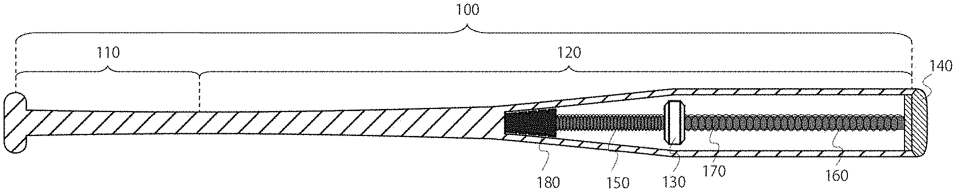
[0020] FIG. 1A is a drawing showing an example of the internal structure of the training bat 100, when the weight 130 is positioned at the initial position.
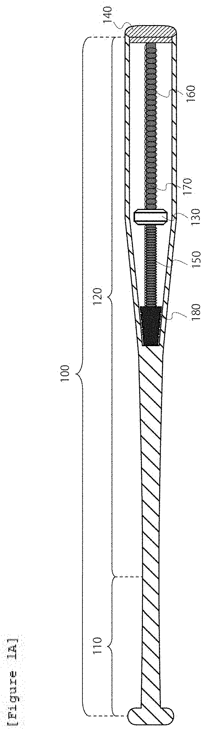
[0021] FIG. 1B is a drawing showing an example of the internal structure of the training bat 100, when the weight 130 is positioned at the tip position.
[0022] FIG. 2A is a drawing showing another example of the internal structure of the training bat 100, when the weight 130 is positioned at the initial position.
[0023] FIG. 2B is a drawing showing another example of the internal structure of the training bat 100, when the weight 130 is positioned at the tip position.
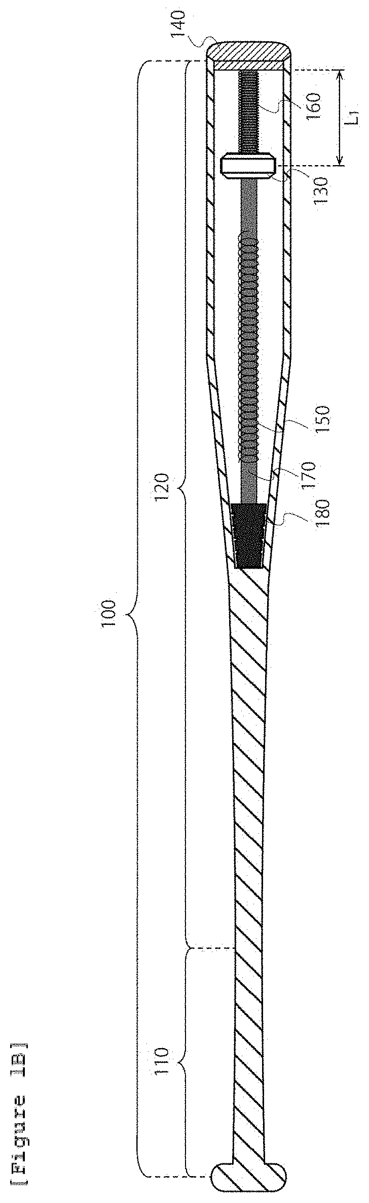
[0024] FIG. 3A is a drawing showing another example of the internal structure of the training bat 100, when the weight 130 is positioned at the initial position.
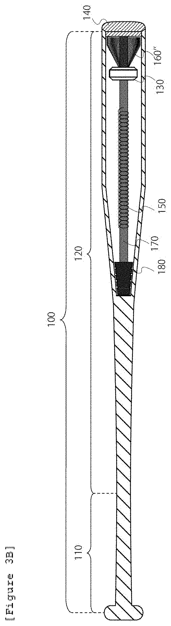
[0025] FIG. 3B is a drawing showing another example of the internal structure of the training bat 100, when the weight 130 is positioned at the tip position.
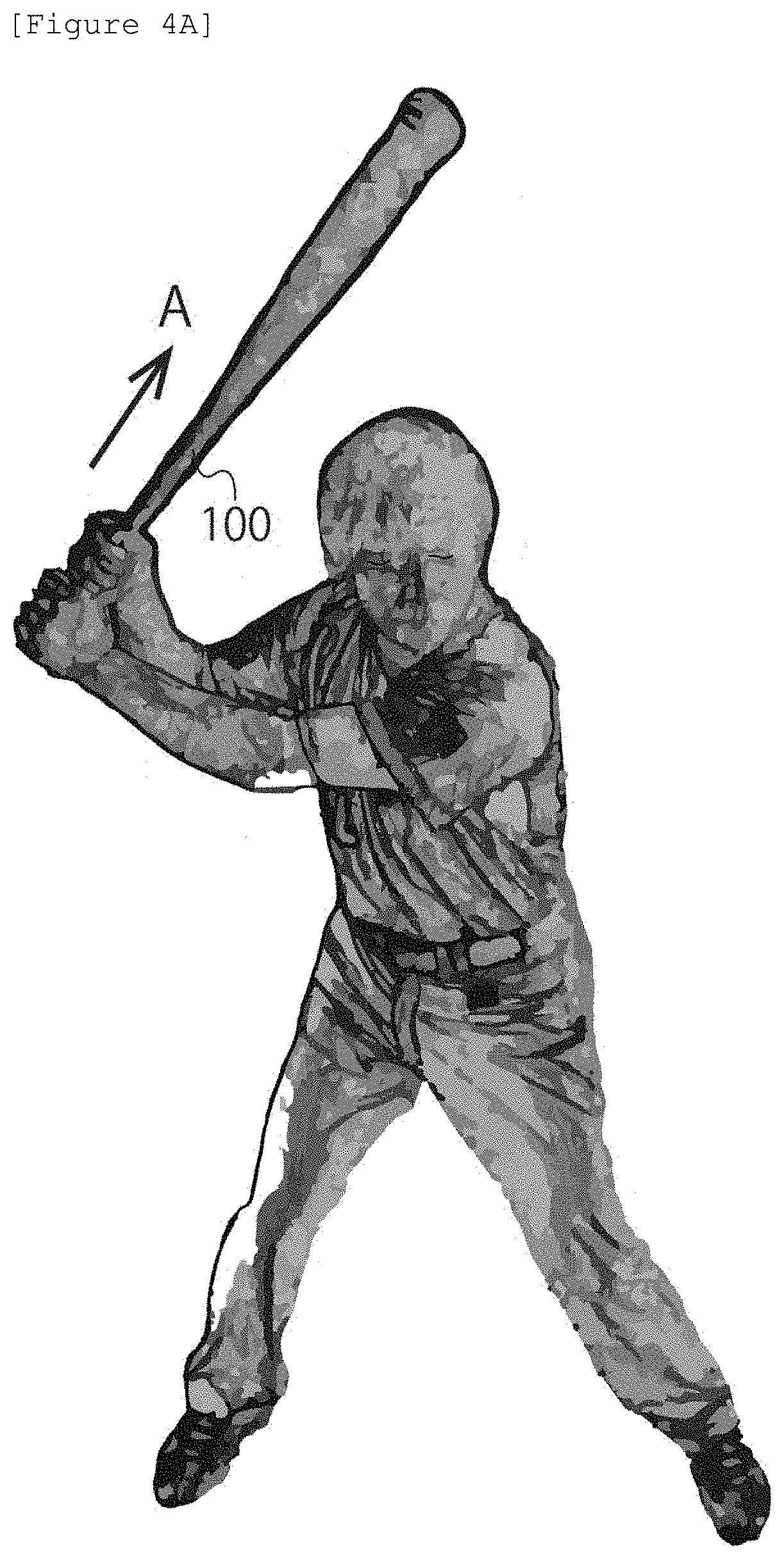
[0026] FIG. 4A is a drawing showing a manner in which the batter makes a top position by holding the training bat 100.
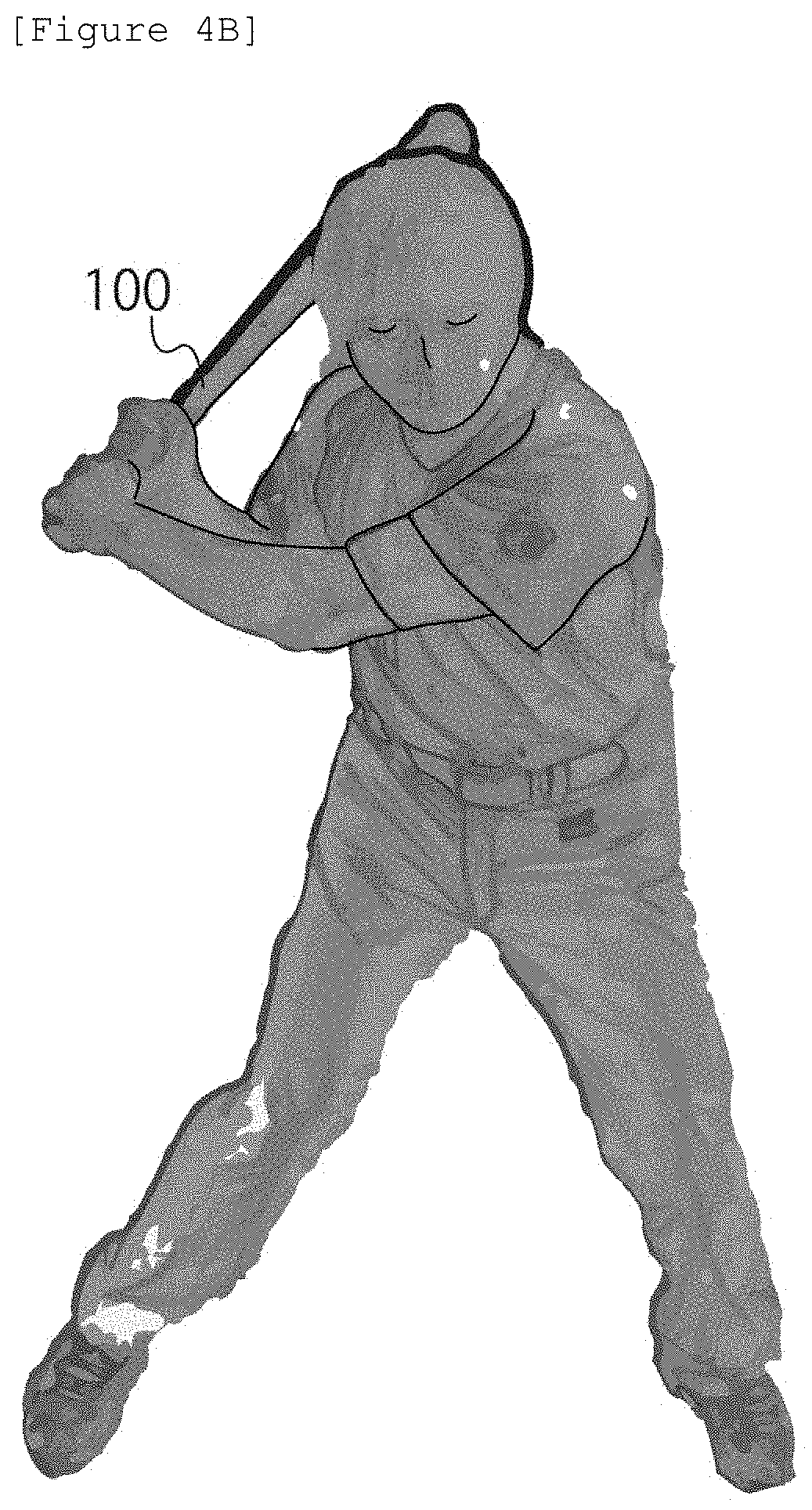
[0027] FIG. 4B is a drawing showing a manner in which the batter starts to swing the training bat 100.
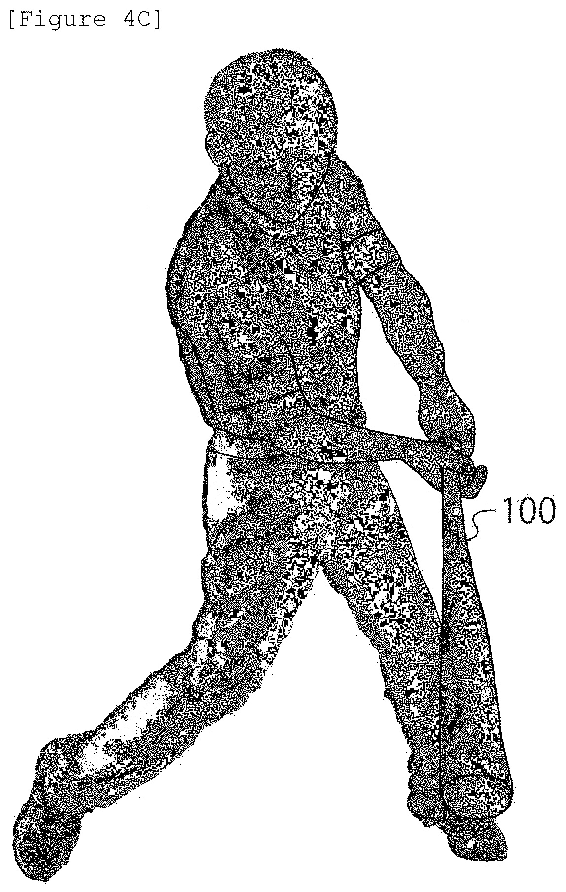
[0028] FIG. 4C is a drawing showing a manner in which the batter hits a ball using the training bat 100.
DESCRIPTION OF THE PREFERRED EMBODIMENTS
[0029] Hereinafter, embodiments of the present invention will be described with reference to the accompanying figures.
1. A Training Bat of the Present Invention
[0030] A training bat 100 will be described below as an example of the training bat of the present invention. Although the training bat 100 is a training bat for hardball baseball, the present invention is not limited to the above bat. The present invention can be applied to a training bat for semi-hard ball baseball and a training bat for rubber-ball baseball. The present invention can be also applied to a training bat for softball.
[0031] The training bat 100 includes a grip portion 110 and a bat body 120. The grip portion 110 is a root portion gripped by hand (typically, a portion around which cloth or rubber is wound in order to prevent the slip of hand). The bat body 120 is a portion other than the grip portion 110 of the training bat 100. A space is formed within at least a part of the bat body 120. The present invention utilizes the space formed within the bat body 120.
[0032] The training bat 100 further includes a weight 130. The weight 130 is positioned within the space formed within the bat body 120. The weight 130 is movable between an initial position and a tip position, within the space formed within the bat body 120. The initial position is defined as a position where the weight 130 is positioned when the training bat 100 is placed vertically while putting the grip portion 110 down. The tip position is defined as a position which is closer to a tip portion 140 of the training bat 100 than the initial position along the longitudinal direction of the training bat 100.
[0033] There is no specific limitation regarding how to make the weight 130. For example, the weight 130 can be made by processing metal lump. Alternatively, the weight 130 can be made by enclosing metal powder in the tube member of polyvinyl chloride.
[0034] The training bat 100 further includes a biasing means for applying a biasing force to the weight 130. This biasing means is configured to apply the biasing force to the weight 130 in a direction where the weight 130 returns from the tip position back to the initial position, when the weight 130 is positioned at the tip position.
[0035] Referring to FIGS. 1A and 1B, examples of the internal structure of the training bat 100 will be described below, in a case where a compression spring 150 having a coil and a compression spring 160 having a coil function as the biasing means.
[0036] The training bat 100 further includes a core bar 170 placed within the space formed within the bat body 120. A through hall is formed within the weight 130 such that the core bar 170 can pass through the weight 130. The core bar 170 is configured to pass through the coil of the compression spring 150, the through hall of the weight 130 and the coil of the compression spring 160, such that the compression spring 150 is positioned at a position closer to the grip portion 110 than the weight 130 and the compression spring 160 is positioned at a position closer to the tip portion 140 of the training bat than the weight 130. Thus, the weight 130 is movable between the initial position and the tip position along the longitudinal direction of the core bar 170.
[0037] In the examples shown in FIGS. 1A and 1B, one end of the compression spring 150 is a free end, and the other end of the compression spring 150 is also a free end. That is, the both ends of the compression spring 150 are not required to be connected to anything or fixed at anything. This is because it is not necessary to connect one end of the compression spring 150 to the weight 130 and it is not necessary to fix the other end of the compression spring 150 at the core bar 170 or the grip portion 110 or the bat body 120, since the movement of the compression spring 150 is constrained by the core bar 170.
[0038] In the examples shown in FIGS. 1A and 1B, one end of the compression spring 160 is a free end, and the other end of the compression spring 160 is also a free end. That is, the both ends of the compression spring 160 are not required to be connected to anything or fixed at anything. This is because it is not necessary to connect one end of the compression spring 160 to the weight 130 and it is not necessary to fix the other end of the compression spring 160 at the core bar 170 or the tip portion 140 of the training bat 110 or the bat body 120, since the movement of the compression spring 160 is constrained by the core bar 170.
[0039] In the examples shown in FIGS. 1A and 1B, a tapered portion 180 is formed at one end of the core bar 170. The tapered portion 180 protrudes outwardly from the core bar 170. For example, the tapered portion 180 can be integrated into the core bar 170 by inserting one end of the core bar 170 into a hall formed in the center portion of the tapered portion 180.
[0040] It is preferable that the tapered portion 180 is formed of elastic body such as rubber. However, the material of the tapered portion 180 is not limited to the above material. It is preferable that the core bar 170 is formed of rigid material such as duralumin, since the core bar 170 is required to be rigid for some extent. However, the material of the core bar 170 is not limited to the above material.
[0041] The tapered portion 180 can be inserted into the grip portion 110 or the bat body 120, such that the outer wall of the tapered portion 180 is in contact with the inner wall of the grip portion 110 or the inner wall of the bat body 120. Thus, the tapered portion 180 functions as a guide portion for guiding the core bar 170, such that the longitudinal direction of the core bar 170 coincides with the longitudinal direction of the training bat 100.
[0042] Further, a recess portion can be formed for receiving the other end of the core bar 170 at the back side of the tip portion 140 of the training bat 100. For example, the tip portion 140 of the training bat 100 can be integrated into the core bar 170 by inserting the other end of the core bar 170 into the recess portion formed in the center portion of the back side of tip portion 140 of the training bat 100. Thus, the recess portion also functions as a guide portion for guiding the core bar 170, such that the longitudinal direction of the core bar 170 coincides with the longitudinal direction of the training bat 100.
[0043] Alternatively, both of the tapered portion 180 and the recess portion formed in the center portion of the back side of tip portion 140 of the training bat 100 can function as a guide portion for guiding the core bar 170, such that the longitudinal direction of the core bar 170 coincides with the longitudinal direction of the training bat 100.
[0044] The weight 130 is configured to be movable between the initial position and the tip position along the longitudinal direction of the core bar 170. Accordingly, the weight 130 is movable between the initial position and the tip position along the longitudinal direction of the training bat 100.
[0045] The core bar 170 can be integrally formed with the tip portion 140 of the training bat 100 using the same material. However, how to form the core bar 170 is not limited to the above manner. For example, the core bar 170 can be a separate member from the tip portion 140 of the training bat 100, and the core bar 170 and the tip portion 140 of the training bat 100 can be adhered to each other.
[0046] When the weight 130 is positioned at the initial position, the compression spring 150 is in a compressed state and the compression spring 160 is in a compressed state. In this case, when the weight 130 moves from the initial position toward the tip position, the compression spring 150 transits from the compressed state toward a neutral state and the compression spring 160 transits from the compressed state toward a further compressed state (i.e., the compression spring 160 is further compressed by the weight 130).
[0047] After the compression spring 150 reaches the neutral state and when the weight 130 further moves toward the tip position, the weight 130 separates from one end of the compression spring 150 and the compression spring 160 is further compressed by the weight 130.
[0048] When the weight 130 is positioned at the tip position, a biasing force in a direction where the weight 130 returns from the tip position back to the initial position is applied to the weight 130.
[0049] Herein, the biasing force in the direction where the weight 130 returns from the tip position back to the initial position is a biasing force by the compression spring 160 (i.e., a force in a direction from the tip position toward the initial position, wherein the amount of the force is proportional to the amount of compression of the compression spring 160). In the tip position, any biasing force by the compression spring 150 is not applied to the weight 130.
[0050] Alternatively, when the weight 130 is positioned at the initial position, the compression spring 150 may be in a compressed state and the compression spring 160 may be in a neutral state (i.e., a state where of the amount of expansion/contraction of the spring is zero). In this case, when the weight 130 moves from the initial position toward the tip position, the compression spring 150 transits from the compressed state toward the neutral state and the compression spring 160 transits from the neural state toward a compressed state (i.e., the compression spring 160 is compressed by the weight 130).
[0051] After the compression spring 150 reaches the neutral state and when the weight 130 further moves toward the tip position, the weight 130 separates from one end of the compression spring 150 and the compression spring 160 is compressed by the weight 130.
[0052] When the weight 130 is positioned at the tip position, a biasing force in a direction where the weight returns from the tip position back to the initial position is applied to the weight 130.
[0053] Herein, the biasing force in the direction where the weight 130 returns from the tip position back to the initial position is a biasing force by the compression spring 160 (i.e., a force in a direction from the tip position toward the initial position, wherein the amount of the force is proportional to the amount of compression of the compression spring 160). In the tip position, any biasing force by the compression spring 150 is not applied to the weight 130.
[0054] Each of the compression spring 150 and the compression spring 160 may be a single spring or may be a spring obtained by coupling a plurality of springs.
[0055] FIG. 1A shows an example of the internal structure of the training bat 100, when the weight 130 is positioned at the initial position.
[0056] The compression spring 150 and the compression spring 160 are configured such that the compression spring 150 is in a compressed state and the compression spring 160 is in a compressed state (or in a neutral state), when the weight 130 is positioned at the initial position. For example, the weight 130 can be positioned at the initial position, by the weight 130 being positioned between the compression spring 150 in the compressed state and the compression spring 160 in the compressed state (or in the neutral state) when the training bat 100 is placed vertically while putting the grip portion 110 down.
[0057] FIG. 1B shows an example of the internal structure of the training bat 100, when the weight 130 is positioned at the tip position.
[0058] The compression spring 160 is configured to apply a biasing force to the weight 130 in a direction where the weight 130 returns from the tip position back to the initial position, when the weight 130 is positioned at the tip position. As described below, when the training bat 100 is swung, a centrifugal force is applied to the weight 130. The spring coefficient of the compression spring 150 and the spring coefficient of the compression spring 160 are pre-designed in order to maintain balance between the centrifugal force applied to the weight 130 and the biasing force applied to the weight 130.
[0059] According to embodiments shown in FIGS. 1A and 1B, as described above, both ends of the compression spring 150 can be free ends and both ends of the compression spring 160 can be free ends. Thereby, it is not necessary to connect/fix both ends of the compression spring 150 to/at anything and it is not necessary to connect/fix both ends of the compression spring 160 to/at anything. Thereby, it is possible to significantly simplify a fabricating process of the training bat 100.
[0060] That is, it is possible to fabricate the training bat 100 easily, by placing the core bar 170 within the space formed within the training bat 100 while the compression spring 150, the weight 130 and the compression spring 160 are passed through the core bar 170 in this order, without requiring any step for connecting/fixing both ends of the compression springs 150 to/at anything and without requiring any step for connecting/fixing both ends of the compression springs 160 to/at anything.
[0061] In the examples shown in FIGS. 1A and 1B, the winding number of the compression spring 160 per unit length is equal to the winding number of the compression spring 150 per unit length. However, the winding number of the compression spring 160 per unit length can be less than the winding number of the compression spring 150 per unit length. This configuration in which the winding number of the compression spring 160 per unit length is less than the winding number of the compression spring 150 per unit length is also within the scope of the present invention.
[0062] According to such configuration, it is possible to reduce the volume of the compression spring 160 when the compression spring 160 has been compressed. Accordingly, such configuration is advantageous in that it is possible to place the tip position of the weight 130 closer to the tip portion 140 of the training bat 100.
[0063] FIGS. 2A and 2B show examples of the internal structure of the training bat 100, in a case where the compression spring 160 shown in FIGS. 1A and 1B has been replaced with a compression spring 160'.
[0064] The winding number of the compression spring 160' per unit length is less than the winding number of the compression spring 160 per unit length. According to the configuration shown in FIG. 2B, it is possible to satisfy a relationship of (L.sub.2 shown in FIG. 2B)<(L.sub.1 shown in FIG. 1B). This is because, it is possible to place the tip position of the weight 130 closer to the tip portion 140 of the training bat 100, since the winding number of the compression spring 160' per unit length is less than the winding number of the compression spring 160 per unit length.
[0065] In at least this point, the configuration shown in FIGS. 2A and 2B is advantageous over the configuration shown in FIGS. 1A and 1B. Herein, L.sub.2 denotes, in the configuration shown in FIG. 2B, a distance between the weight 130 and the tip portion 140 of the training bat 100 when the weight 130 is positioned at the tip position, whereas L.sub.1 denotes, in the configuration shown in FIG. 1B, a distance between the weight 130 and the tip portion 140 of the training bat 100 when the weight 130 is positioned at the tip position.
[0066] In the examples shown in FIGS. 1A, 1B, 2A and 2B, the radius of the coil of the compression spring 160 is maintained to be constant. However, it is possible to configure the compression spring 160 such that the radius of the coil of the compression spring 160 is monotonically increased (i.e., the radius of the coil maintains or increases) as the coil of the compression spring 160 becomes closer to the tip portion 140 of the training bat 100. This configuration in which the radius of the coil of the compression spring 160 is monotonically increased as the coil of the compression spring 160 becomes closer to the tip portion 140 of the training bat 100 is also within the scope of the present invention.
[0067] According to this configuration, it is possible to move the weight 130 toward the tip portion 140 of the training bat 100, more slowly compared with the configuration in which the radius of the coil of the compression spring 160 is maintained to be constant, and it is possible to gradually reduce the moving speed of the weight 130 as the weight 130 becomes closer to the tip portion 140 of the training bat 100.
[0068] FIGS. 3A and 3B show examples of the internal structure of the training bat 100, in a case where the compression spring 160' shown in FIGS. 2A and 2B has been replaced with a compression spring 160''.
[0069] The compression spring 160'' is a conical compression spring. The radius of the coil of the compression spring 160'' is increased as the coil of the compression spring 160'' becomes closer to the tip portion 140 of the training bat 100.
[0070] According to the configuration shown in FIGS. 3A and 3B, it is possible to move the weight 130 toward the tip portion 140 of the training bat 100, more slowly compared with the configuration shown in FIGS. 1A and 1B as well as the configuration shown in FIGS. 2A and 2B, and it is possible to gradually reduce the moving speed of the weight 130 as the weight 130 becomes closer to the tip portion 140 of the training bat 100.
[0071] In at least this point, the configuration shown in FIGS. 3A and 3B is advantageous over the configuration shown in FIGS. 1A and 1B as well as the configuration shown in FIGS. 2A and 2B.
[0072] In the examples shown in FIGS. 1A, 1B, 2A, 2B, 3A and 3B, the grip portion 110 is formed to be solid and a part of the bat body 120 is formed to be hollow. However, the internal structures of the grip portion 110 and the bat body 120 are not limited to the above structures. The bat body 120 can have any internal structure, as far as a space is formed within at least a part of the bat body 120 and the weight 130 is movable, within the space, between the initial position and the tip position.
[0073] Further, in the examples shown in FIGS. 1A, 1B, 2A, 2B, 3A and 3B, the compression spring 150 and the compression spring 160 have been described above as an example of the biasing means for generating a biasing force. However, the example of the biasing means of the present invention is not limited to the above example. It is possible to use any biasing means for generating a biasing force, instead of the compression spring 150 and/or the compression spring 160.
[0074] Further, in the training bat 100 shown in FIGS. 1A, 1B, 2A, 2B, 3A and 3B, the tip portion 140 of the training bat 100 can be configured to be opened or closed. In this case, the training bat 100 can be configured to exchange the weight 130 when the tip portion 140 of the training bat 100 is opened. For example, when various types of weights having different weights (e.g., 500g, 250g and 100g) are prepared, it is possible to use a single training bat 100 as a plurality of training bats having different weights by exchanging the various types of weights. Alternatively, the training bat 100 can be configured to exchange at least one of the compression spring 150 and the compression spring 160 when the tip portion 140 of the training bat 100 is opened.
[0075] The configuration for the tip portion 140 of the training bat 100 can be any configuration as far as the tip portion 140 of the training bat 100 is configured to be opened or closed. For example, the tip portion 140 of the training bat 100 can be detachably coupled to the bat body 120 by engaging the thread ridge (or the thread groove) formed on the tip portion 140 with the thread groove (or the thread ridge) formed on the bat body 120. Alternatively, the tip portion 140 of the training bat 100 can be detachably coupled to the bat body 120 by inserting the convex portion formed on the tip portion 140 into the concave portion formed on the bat body 120.
[0076] Further, the training bat 100 is typically a metal bat. The metal bat does not require the step of forming a space within the bat body, since the grip portion and the bat body of the metal bat should be originally hollow. Accordingly, the metal bat is suitable to fabricate the training bat of the present invention. However, the training bat of the present invention is not limited to the metal bat. The training bat of the present invention can be a bat made of any material, as far as a space is formed within at least a part of the bat body. For example, the training bat of the present invention can be a bat made of wood, in which a space is formed within the bat body by hollowing out at least a part of the bat body.
2. A Batting Training Using the Training Bat of the Present Invention
[0077] The training bat 100 having the internal structures shown in FIGS. 1A and 1B is the same as the conventional bat in appearance. Accordingly, The training bat 100 can be used to perform batting training such as toss batting, tee batting and free batting (i.e., any batting training for a batter to hit a ball), similar to the conventional bat. This is a case for the training bat 100 having the internal structures shown in FIGS. 2A and 2B. This is also a case for the training bat 100 having the internal structures shown in FIGS. 3A and 3B.
[0078] FIGS. 4A to 4C show a manner in which the batter holds and swings the training bat 100.
[0079] FIG. 4A shows a manner in which the batter makes a top position by holding the training bat 100. At this timing, the weight 130 is positioned at the initial position within the training bat 100. The batter moves the training bat 100 in the longitudinal direction (the direction of arrow A shown in FIG. 4A) of the training bat 100, immediately before the batter starts to swing the training bat 100 from the top position shown in FIG. 4A. This movement of the training bat 100 causes the weight 130 within the training bat 100 to move from the initial position toward the tip position. As a result, a biasing force is applied to the weight 130 in a direction where the weight 130 returns from the tip position back to the initial position. At the same time when the biasing force is applied to the weight 130, a centrifugal force is applied to the weight 130 by the batter starting to swing the training bat 100.
[0080] Thus, the weight 130 remains near the tip position by balancing the biasing fore applied to the weight 130 and the centrifugal force applied to the weight 130. Thereby, the batter can swing the training bat 100 while continuously feeling a weight near the tip portion 140 of the training bat 100 during a time period from time when the batter starts to swing the training bat 100, through time when the batter hits a ball, to time when the batter finishes the batter's follow-through.
[0081] FIG. 4B shows a manner in which the batter starts to swing the training bat 100. FIG. 4C shows a manner in which the batter hits a ball using the training bat 100.
[0082] According to the batting training using the training bat 100, the batter can learn a feeling that "the batter feels a weight near the tip portion of the bat immediately before the batter starts to swing the bat", and that "the batter swings out the bat while the batter feels the weight". This feeling is important for the batter. It is possible to improve how to start to swing the bat and how to swing out the bat by learning the above feeling.
[0083] According to the training bat 100 having the internal structure shown in FIGS. 1A, 1B, 2A, 2B, 3A and 3B, due to the existence of the compression springs 150 and 160 (or the compression springs 150 and 160' or the compression springs 150 and 160''), the batter can feel "floating feeling" of the weight 130 when the weight 130 is moving from the initial position toward the tip position. Thereby, the batter can naturally feel the movement of a weight and can swing out the bat while feeling the weight near the tip portion of the bat. Further, by using the compression spring rather than an extension spring, it is possible that both ends of the compression spring are free ends, without fixing both ends of the compression spring at anything. Thereby, it is possible to significantly simplify the fabricating process of the training bat 100.
[0084] In particular, according to the training bat 100 having the internal structure shown in FIGS. 3A and 3B, due to the existence of the conical compression spring 160'', the weight 130 can move more slowly toward the tip portion 140 of the training bat 100 and the moving speed of the weight 130 can be gradually reduced as the weight 130 approaches the tip portion 140 of the training bat 100, compared with the training bat 100 having the internal structure shown in FIGS. 1A, 1B, 2A and 2B.
[0085] According to the training bat 100 having the internal structure shown in FIGS. 3A and 3B, the batter can continuously feel the weight near the tip portion of the bat, even after the batter starts to swing the bat from the top position.
[0086] Accordingly, according to the training bat 100 having the internal structure shown in FIGS. 3A and 3B, the batter can learn a feeling that the batter feels the weight near the tip portion of the bat for a longer time period, and that the batter swings out the bat while the batter feels the weight, compared with the training bat 100 having the internal structure shown in FIGS. 1A, 1B, 2A and 2B.
[0087] Thus, it is important for the batter to feel the weight near the tip portion of the bat for a longer time period in a process from the start of swing of the bat to the end of swing of the bat. It is possible to further improve how to start to swing the bat and how to swing out the bat by learning the above feeling.
[0088] The inventor has been a coach of the Baseball team in Japan called "All Hirakata Boys" for elementary school students for long years, and has been coaching the batting for elementary school students from the first grade to the sixth grade.
[0089] Since the elementary school students at lower grade has much less power than the elementary school students at higher grade, it is long-time unsettled issue for the inventor how to coach the batting for the elementary school students at lower grade. The present invention has been created based on the result of the inventor's consideration regarding how to coach the batting for the elementary school students at lower grade in order to settle the above issue.
[0090] By continuously performing batting training using the training bat 100, it is possible for the elementary school student at lower grade to hit a ball thrown by the elementary school student at higher grade. This is because it is possible for the batter to complete a swing which is capable of transmitting the batter's power to a ball without any waste, by learning the above feeding that "the batter feels a weight near the tip portion of the bat immediately before the batter starts to swing the bat", and that "the batter swings out the bat while the batter feels the weight".
[0091] The batting training using the training bat 100 is also useful for all baseball players such as junior high school students, high school students, university students and adults, in addition to the elementary school students. This is because the swing which is capable of transmitting the batter's power to a ball without any waste is useful for all baseball players, regardless of the batter's power.
[0092] The swing which has been completed in this way should be considered as a swing enabling the tip portion of the bat running faster until reaching an impact with a ball while it may appear that the bat goes a long way round, contrary to the swing enabling the bat running at the minimum distance with an inside out motion until reaching an impact with a ball, which is conventionally considered as an ideal swing.
[0093] The above swing is far from the conventional common sense for baseball. The above swing should cause "swing revolution", which follows "fly ball revolution" which has become famous recently. By continuously performing batting training using the training bat 100, it is possible for the batter to get a completed swing based on a new batting theory.
[0094] As described above, the present invention is exemplified by the use of its preferred embodiments. However, the present invention should not be interpreted solely based on the embodiments described above. It is understood that the scope of the present invention should be interpreted solely based on the claims. It is also understood that those skilled in the art can implement equivalent scope of technology, based on the description of the present invention and common knowledge from the description of the detailed preferred embodiments of the present invention. Various other modifications will be apparent to and can be readily made by those skilled in the art without departing from the scope and spirit of this invention. Accordingly, it is not intended that the scope of the claims appended hereto be limited to the description as set forth herein, but rather that the claims be broadly construed.
INDUSTRIAL APPLICABILITY
[0095] The present invention is useful to provide a training bat and the like which can be used to perform batting trainings such as toss batting, tee batting and free batting (i.e., any batting training for a batter to hit a ball).
LIST OF REFERENCE NUMERALS
[0096] 100 training bat [0097] 110 grip portion [0098] 120 bat body [0099] 130 weight [0100] 140 tip portion [0101] 150 compression spring [0102] 160 compression spring [0103] 160' compression spring [0104] 160'' compression spring [0105] 170 core bar [0106] 180 tapered portion (guide portion)
* * * * *
References
D00000
D00001
D00002
D00003
D00004
D00005
D00006
D00007
D00008
D00009
XML
uspto.report is an independent third-party trademark research tool that is not affiliated, endorsed, or sponsored by the United States Patent and Trademark Office (USPTO) or any other governmental organization. The information provided by uspto.report is based on publicly available data at the time of writing and is intended for informational purposes only.
While we strive to provide accurate and up-to-date information, we do not guarantee the accuracy, completeness, reliability, or suitability of the information displayed on this site. The use of this site is at your own risk. Any reliance you place on such information is therefore strictly at your own risk.
All official trademark data, including owner information, should be verified by visiting the official USPTO website at www.uspto.gov. This site is not intended to replace professional legal advice and should not be used as a substitute for consulting with a legal professional who is knowledgeable about trademark law.