Controlled Volume Dropper
RICCI; Alfredo
U.S. patent application number 16/313514 was filed with the patent office on 2020-06-04 for controlled volume dropper. The applicant listed for this patent is Dompe' Farmaceutici S.P.A.. Invention is credited to Alfredo RICCI.
| Application Number | 20200170836 16/313514 |
| Document ID | / |
| Family ID | 56551445 |
| Filed Date | 2020-06-04 |


| United States Patent Application | 20200170836 |
| Kind Code | A1 |
| RICCI; Alfredo | June 4, 2020 |
CONTROLLED VOLUME DROPPER
Abstract
A medical device (100) for the instillation of medical products in droplet form is described, said device comprising a hollow cylindrical body (10) and a rod (20) slidably mobile inside the hollow cylindrical body (10) and provided with a head (21) on which a rubber washer (40) is fixed, which washer, during the sliding of the rod (20), is in contact with an inner surface of the hollow cylindrical body (10). The rod (20) is formed as two portions (22, 24) of different diameter and the device (100) further comprises a sealing bush (30) between the hollow cylindrical body (10) and the rod (20), wherein there is provided a stop (32) which prevents the passage of the portion (22) with a larger circular section of the rod (20).
| Inventors: | RICCI; Alfredo; (Cappelle sul Tavo (PE), IT) | ||||||||||
| Applicant: |
|
||||||||||
|---|---|---|---|---|---|---|---|---|---|---|---|
| Family ID: | 56551445 | ||||||||||
| Appl. No.: | 16/313514 | ||||||||||
| Filed: | June 29, 2017 | ||||||||||
| PCT Filed: | June 29, 2017 | ||||||||||
| PCT NO: | PCT/IB2017/053906 | ||||||||||
| 371 Date: | December 27, 2018 |
| Current U.S. Class: | 1/1 |
| Current CPC Class: | A61F 9/0008 20130101 |
| International Class: | A61F 9/00 20060101 A61F009/00 |
Foreign Application Data
| Date | Code | Application Number |
|---|---|---|
| Jun 30, 2016 | IT | 102016000031850 |
Claims
1. Medical device (100) for the instillation of medical products in droplet form, consisting of: a hollow cylindrical body (10); a rod (30) slidably mobile inside the hollow cylindrical body (10) and provided with a head (21) on which a rubber washer (40) is fixed, which washer, during sliding of the rod (30), is in contact with the inner surface of the hollow cylindrical body (10); characterized in that: the rod (20) is formed as two portions (22, 24) of different diameter and in that the device (100) comprises a sealing bush (30) between hollow cylindrical body (10) and rod (20), wherein there is provided a stop (32) which prevents the passage of the portion (22) with a larger circular section of the rod (20).
2. Device (100) according to claim 1, wherein the hollow cylindrical body (10) has a front end portion (12) having an internal diameter smaller than the internal diameter of the hollow cylindrical body (10), a mechanical stop (19) being defined on said front end portion (12),
3. Device (100) according to claim 2, wherein the portion (22) with a larger circular section of the rod (20) has a stroke limited between said stop (32) and said mechanical stop (19).
4. Device (100) according to claim 2 or claim 3, wherein the front end portion (12) has an outer surface (15) of polygonal shape designed to improve gripping of the device (100) by a user.
5. Device (100) according to any one of the preceding claims, wherein the hollow cylindrical body (10) has a rear end portion (14) which defines a seat (13) for housing said sealing bush (30).
6. Device (100) according to any one of the preceding claims, wherein said sealing bush (30) has at least one interlocking coupling means (34) configured to co-operate with complementary interlocking coupling means (17) formed in the hollow cylindrical body (10).
7. Device (100) according to claim 6, wherein said interlocking coupling means (34) of the sealing bush (30) consist of a pair of grooves (34) formed on an outer surface (33) of the sealing bush and said complementary interlocking coupling means (17) of the hollow cylindrical body (10) consist of a rib (17) formed on an inner surface (18) of the rear end portion (14) of the hollow cylindrical body (10), or vice versa.
8. Device (100) according to any one of the preceding claims, also comprising a slider (50) which can be coupled with the rod (20) at a free end (26) of the rod (20).
9. Device (100) according to claim 8, wherein said slider (50) comprises a hollow body (52) which defines a seat (51) for housing said free end (26) of the rod (20).
10. Device (100) according to claim 9, wherein said slider (50) has at least one interlocking coupling means (53) configured to co-operate with complementary interlocking coupling means (27) formed in the rod (20).
11. Device (100) according to claim 10, wherein said interlocking coupling means (53) of the slider (50) consist of a pair of grooves (53) formed on an inner surface of the seat (51) and said complementary interlocking coupling means (27) of the rod (20) consist of a pair of ribs (27) formed at the free end (26) of the rod (20), or vice versa.
Description
FIELD OF THE INVENTION
[0001] The present invention relates to a dropper or syringe device for instilling medical products in small doses and for drawing off medical liquids from bottles on which an adapter for a Luer lock fitting may be mounted. More particularly the present invention relates to a controlled volume dropper.
[0002] The field of application of the invention is that regarding medical instruments for the application of drugs, in particular eye solutions, by means of instillation. In detail, the controlled volume dropper according to the invention comes under the category of those droppers which are formed by a hollow cylindrical body, inside which a sealed plunger slides, and which inject or draw fluids in the human body.
[0003] The controlled volume dropper is a device which aspirates and administers, but does not inject, a relatively small and predetermined volume of medical product. The invention allows the administration of small doses of fluid, which would require a cross-section of the cylinder/reservoir too small to be handled, using a syringe of common dimensions.
[0004] As is known in the art, the operating principle of syringe injectors is well documented, but here the relevant state of the art is that concerning syringes to which a system for mechanical control of the volume of administered fluid is applied.
BACKGROUND OF THE INVENTION
[0005] The state of the art is represented by a large number of inventions and solutions aimed at obtaining the dispensing of a controlled volume of fluid.
[0006] Document CN 2021 13430U proposes a double volumetric chamber, with the second chamber having a slimmer and graduated section. Patent CN 202982801 U proposes a similar solution in which however the two reservoirs are contained in the same cylinder. Patent TW 201402165A introduces a mechanical stop which limits, in advance, the stroke of the plunger, determining the volume of liquid to be injected. Patent WO2014/164419 consists of the "fusion" of the two systems, having a double chamber and a mechanical stop of the plunger. Similarly, WO 2014/164685, as well as representing a similar volumetric control system, places the two reservoirs in communication, one inserted inside the other, so that the pressure of the fluid between the two chambers remains constant.
[0007] Most of the systems present on the market have two major drawbacks: [0008] Despite the fact they have to instill small controlled volumes they are bulky, complex to operate and not easy to handle. In short, they do not allow use with one hand only. [0009] The second drawback is that they are devices which are complex to assemble. Assembly of the parts results in high production costs and, given their complexity, the parts are subject to misalignment, losing the capacity for operation and making use difficult.
SUMMARY OF THE INVENTION
[0010] The main object of the present invention is to provide a dropper configured so as to overcome, or at least reduce, the drawbacks stated above with reference to devices of the known type.
[0011] More particularly the present invention overcomes these drawbacks in that: [0012] it functions like a normal syringe which instills droplets of product and can be operated with three fingers; [0013] it is made up of mechanical elements--cylinder, rod and bearing surfaces or stops--that are perfectly matching, free from play or joints which may deteriorate with use; [0014] it allows the drug to be easily drawn from its container.
[0015] According to the invention a medical device is therefore provided for the instillation of medical products, in particular ophthalmic products, in droplet form, comprising: [0016] a hollow cylindrical body; [0017] a rod, slidably mobile inside the hollow cylindrical body and provided with a head on which a rubber washer is fixed, which washer, during sliding of the rod, is in contact with the inner surface of the hollow cylindrical body.
[0018] The device is characterized in that the rod is formed as two portions of different diameter and in that it comprises a sealing bush between the hollow cylindrical body and the rod, wherein there is provided a stop which prevents the passage of the portion with a larger circular section of the rod.
[0019] Moreover the device has, in the Luer lock zone, instead of a cylindrical surface, bevelled flat faces, so that the side surface is not round but polygonal. This shape increases considerably the grip for the patient who has to "screw" the dropper into an adapter in order to perform removal of the drug and subsequent instillation thereof in the eye.
BRIEF DESCRIPTION OF THE DRAWINGS
[0020] Further features and advantages of the invention will become clearer from the description of a preferred, but not exclusive embodiment of a dropper or syringe device according to the present invention, illustrated by way of a non-limiting example in the accompanying drawings, in which:
[0021] FIG. 1 is a side view of the device according to the invention, in the fully open position, or position where the rod is fully retracted from the hollow cylindrical body.
[0022] FIG. 2 is a rear view of the device of FIG. 1, in the fully closed position, or position where the rod is fully inserted inside the hollow cylindrical body.
[0023] FIG. 3 is a cross-sectional view, along line III-Ill of FIG. 2.
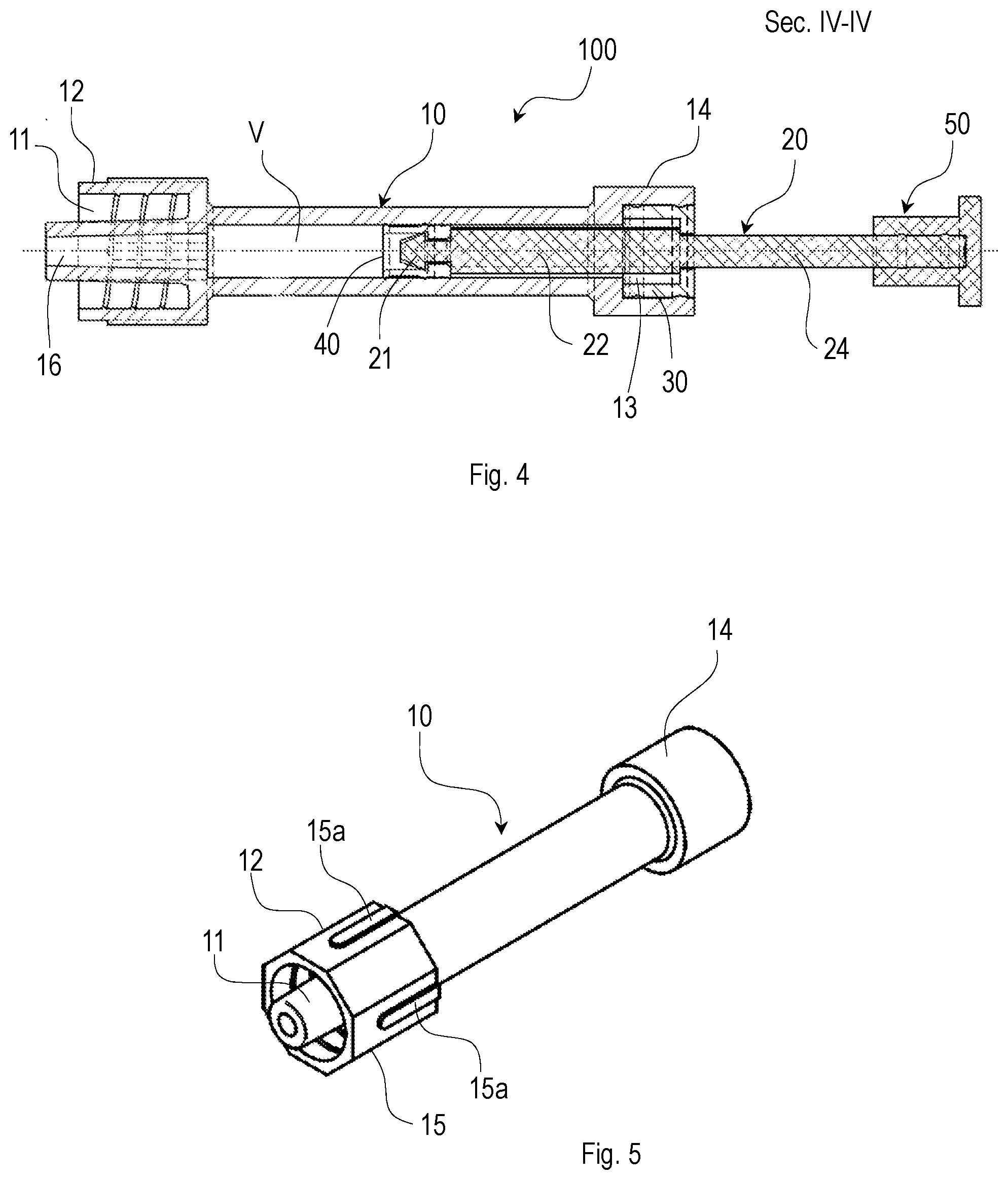
[0024] FIG. 4 is a cross-sectional view, along line IV-IV of FIG. 1.
[0025] FIG. 5 is a perspective view of the hollow cylindrical body of the device according to the invention, which shows in detail the polygonal gripping surface in the Luer lock fitting zone.
[0026] FIG. 6 is a longitudinally sectioned view of the hollow cylindrical body of FIG. 5.
[0027] FIG. 6a is a detailed view of the detail shown encircled in FIG. 6.
[0028] FIG. 7 is a perspective view of the sealing bush of the device according to the invention.
[0029] FIG. 8 is a rear view of the sealing bush of FIG. 7.
[0030] FIG. 9 is a cross-sectional view, along line IX-IX of FIG. 8.
[0031] FIG. 10 is a side view of the rod of the device according to the invention.
[0032] FIG. 11 is a perspective view of a slider of the device according to the invention.
[0033] FIG. 12 is a front view of the slider of FIG. 11.
[0034] FIG. 13 is a cross-sectional view, along line XIII-XIII of FIG. 12.
DETAILED DESCRIPTION OF A PREFERRED EMBODIMENT OF THE INVENTION
[0035] The invention will be described here below by way of an illustrative but non-limiting example, with particular reference to some illustrative embodiments.
[0036] The invention consists of a device, hereinafter referred to as dropper, with can be used to draw and supply or instill a small known and predetermined quantity of a medical product.
[0037] With reference to FIGS. 1 to 4, the dropper, denoted in general by reference numeral 100, comprises a hollow cylindrical body 10 and a rod 20, slidably mobile inside the hollow cylindrical body 10.
[0038] The hollow cylindrical body 10 has a front end portion 12 and a rear end portion 14, each of which has an external diameter greater than the external diameter of the hollow cylindrical body 10.
[0039] The front end portion 12 is provided with a Luer lock fitting 11 and has an internal diameter smaller than the internal diameter of the hollow cylindrical body 10. The internal diameter of the front end portion 12 preferably tapers in a funnel shape, thereby defining a passage 16 for the exit of one or more drops of medical liquid to be instilled. At the front end portion 12, in the inner surface of the hollow cylindrical body 10, there is therefore formed a bearing surface or mechanical stop 19 which can be seen in FIG. 6.
[0040] Preferably, and as shown in detail in FIG. 5, the front end portion 12 of the hollow cylindrical body 10 has a faceted outer surface 15 with a preferably octagonal cross-section. This particular form of the outer surface 15 improves, advantageously, gripping of the Luer lock fitting by a user, during engagement/disengagement of the dropper 100 onto/from a corresponding Luer lock adapter provided on the opening of a bottle or vial containing the medical liquid, for example an eye solution, which is to be drawn and subsequently instilled in the eye.
[0041] In a preferred embodiment, one or more faces of the faceted outer surface 15 are provided with ridges 15a, preferably four ridges 15a formed on alternating faces of the faceted outer surface 15.
[0042] Referring to FIG. 6, the rear end portion 14 has an internal diameter greater than the internal diameter of the hollow cylindrical body 10, so as to define a seat 13 for the housing of a sealing bush 30--shown in detail in FIGS. 7 to 9--which will be described in detail here below.
[0043] As shown in greater detail in FIG. 10, the rod 20 of the dropper 100 is provided with two portions. More particularly the rod 20 has a first portion 22 with a larger circular section and a second portion 24 with a smaller circular section. The first and the second portions 22, 24 of the rod 20 are such that the first portion 22 cannot come out of the hollow cylindrical body 10, while the second portion 24 can slide in and out of the hollow cylindrical body 10 during the stroke of the rod 20. At the transition zone between the first portion 22 and the second portion 24 of the rod 20 there is therefore a shoulder 25, the function of which will become clearer in the following of the present description.
[0044] The rod 20 also has a head 21, extending from the portion 22 with a larger circular section, on which a rubber washer 40 is fixed, for example interlocked or glued (FIGS. 3 and 4). During the stroke of the rod 20 inside the hollow cylindrical body 10, the rubber washer 40 stays in contact with the inner surface of the hollow cylindrical body 10 and in the position of total closure of the dropper 100--shown in FIG. 3--the rubber washer 40 abuts against the bearing surface 19 of the hollow cylindrical body 10.
[0045] As shown in greater detail in FIGS. 7 to 9, the sealing bush 30 has an external diameter substantially the same as the internal diameter of the rear end portion 14 of the hollow cylindrical body 10. The sealing bush 30 has also an inner surface 31 provided with a bearing surface or mechanical stop 32, against which, during use of the dropper 100, the shoulder 25 of the rod 20 can abut, as will become clearer here below.
[0046] Moreover, at an outer surface 33 thereof, the sealing bush 30 has at least one groove 34, preferably an annular groove, configured to couple interlockingly with a corresponding rib or ridge 17 formed on an inner surface 18 of the seat 13 of the rear end portion 14 of the hollow cylindrical body 10. In the embodiment illustrated in the drawings a pair of annular grooves 34 and a rib 17 are provided. Alternatively it is possible to provide at least one rib or ridge on the sealing bush 30 and corresponding grooves in the hollow cylindrical body 10.
[0047] This interlocking coupling between the sealing bush 30 and the hollow cylindrical body 10 facilitates, advantageously, the mode of assembly of these two components, and therefore of the dropper 100 according to the invention.
[0048] The rod 20 is stopped, during its stroke, by the sudden variation in cross-section or bearing surface 25 between the first portion 22 and the second portion 24, which is marked and without connecting radii, and by the sealing bush 30.
[0049] Owing to this particular shape thereof and to the presence of the sealing bush 30, the rod 20 cannot come out completely from the hollow cylindrical body 10 of the device 100, since, during total opening of the dropper 100, shown in FIG. 4, the first portion 22 with a larger circular section of the rod 20 encounters the sealing bush 30, in particular its bearing surface or mechanical stop 32, which is such as to allow only the second portion 24 with a smaller circular section of the rod 20 to pass, but not that with a larger circular section 22.
[0050] The first portion 22 with larger circular section of the rod 20 has a predetermined length. In this way an internal volume V of the hollow cylindrical body 10 is defined. Typically the predefined internal volume V of the hollow cylindrical body 10 is equal to approximately 2-3 drops of medical liquid, i.e. about 135 mm.sup.3.
[0051] The sudden variation in cross-section of the rod 20 and the bearing surface or mechanical stop 32 of the sealing bush 30 determine therefore a mechanical stop which limits the maximum aspiration of medical product and allows the creation of a mechanical bearing surface between the rod 20 and the sealing bush 30.
[0052] Moreover the narrowing of the cross-section of the rod 20, together with the sealing bush 30, allows a reliable and repeatable mechanical bearing surface to be obtained, this also being simple to realize.
[0053] Furthermore, during the sliding movement of the rod 20 inside the hollow cylindrical body 10, there is controlled friction between the rubber washer 40 and the inner surface of the hollow cylindrical body 10. This function is of great importance for regulating the flow of the single drops which must be instilled. The rubber washer 40, placed in contact with the hollow cylindrical body 10 and interlocked with the rod 20, performs this function.
[0054] The dropper 100 further comprises a slider 50, shown in detail in FIGS. 11 to 13, which is interlockingly coupled on the free end 26 of the second portion 24 with a smaller circular section of the rod 20 (FIG. 3).
[0055] During use the slider 50 is configured to be grasped, with three fingers, by the user of the dropper 100 so as to operate the rod 20 inside the hollow cylindrical body 10 and draw and subsequently instill a quantity of eye solution inside the eye.
[0056] The slider 50 comprises, in particular, a hollow--preferably cylindrical--body 52 from which a flange 54 extends. The hollow body 52 defines a seat 51 for housing the free end 26 of the second portion 24 with a smaller circular section of the rod 20.
[0057] An inner surface of the seat 51 is provided with at least one groove, preferably an annular groove, in the embodiment a pair of annular grooves 53, configured to interlockingly couple with respective ribs 27 formed on the free end 26 of the rod 20. This interlocking coupling between the rod 20 and the slider 50 facilitates, advantageously, the mode of assembly of these two components, and therefore of the dropper 100 according to the invention. Alternatively, it is possible to provide at least one rib on the free end 26 of the second portion 24 with a smaller circular section of the rod 20 and corresponding grooves on the inner surface of the seat 51 of the slider 50.
[0058] With reference to FIGS. 3 and 4, it is now disclosed the operation of the dropper 100 according to the invention.
[0059] Here below reference will be made to an ophthalmic liquid, but it is understood that entirely the same considerations are applicable in the case of any other medical liquid which is to be instilled.
[0060] It is assumed that a user must instill a predetermined quantity of eye solution, typically 2-3 drops, in his/her eye. In the initial state the dropper 100 is in its completely closed position, shown in FIG. 3, with the rubber washer 40 abutting against the bearing surface or mechanical stop 19 of the hollow cylindrical body 10. First of all the user couples the Luer lock fitting 11 of the dropper 100 with a Luer lock adapter (not shown) provided on the mouth of a vial (not shown) containing the eye solution to be instilled. This coupling operation is facilitated by the faceted form of the outer surface 15 of the front end portion 14 of the hollow cylindrical body 10.
[0061] Subsequently the user, by acting on the slider 50 of the dropper 100, retracts the rod 20 inside the hollow cylindrical body 10, until the shoulder 25 of the rod 20 abuts against the bearing surface or mechanical stop 32 of the sealing bush 30. This condition is shown in FIG. 4. Following this retracting movement the volume V of the hollow cylindrical body 10 is filled with the predetermined quantity of eye solution. Once the quantity of eye solution necessary has been drawn from the vial, the user disengages the dropper from the vial and then proceeds with instillation of the eye solution in the eye. For this purpose, he or she acts again on the slider 50, exerting a pushing force on it so as to move the rod 20 forwards inside the hollow cylindrical body 10, until the rubber washer 40 abuts against the bearing surface or mechanical stop 19 of the hollow cylindrical body 10, with consequent complete instillation of the eye solution (FIG. 3). The operation of instillation can then be considered terminated.
Advantages of the Invention
[0062] In the tests carried out, using prototypes, the controlled volume dropper demonstrated considerable ease of use and excellent duration of the functional and mechanical features over a prolonged period of time.
[0063] The manufacturing and assembly costs are extremely low.
[0064] These two elements in combination, that is ease of use and low cost, make diffusion and marketing of the controlled-volume dropper relatively easy.
[0065] The device is held with only three fingers. The dimensions of the device have been specifically designed for this purpose. Moreover the movement the patient must perform in order to instill a drop in the eye is in the direction of instillation of the drop, i.e. the patient has to press on the slider. Since no lateral forces are imparted to the device, it does not move sideways, does not wobble or change position and allows the patient to perform instillation easily and safely, also at a distance very close to the eye.
[0066] From the description provided the features of the dropper forming the subject of the present invention are clear, as are the associated advantages.
[0067] Further variations of the embodiment described above are possible, without departing from the teaching of the invention.
[0068] Finally it is clear, that the dropper designed in this way may be subject to numerous changes and variations; moreover all the details can be replaced by technically equivalent elements. In practice any materials and dimensions may be used according to technical needs.
* * * * *
D00000
D00001
D00002
D00003
D00004
XML
uspto.report is an independent third-party trademark research tool that is not affiliated, endorsed, or sponsored by the United States Patent and Trademark Office (USPTO) or any other governmental organization. The information provided by uspto.report is based on publicly available data at the time of writing and is intended for informational purposes only.
While we strive to provide accurate and up-to-date information, we do not guarantee the accuracy, completeness, reliability, or suitability of the information displayed on this site. The use of this site is at your own risk. Any reliance you place on such information is therefore strictly at your own risk.
All official trademark data, including owner information, should be verified by visiting the official USPTO website at www.uspto.gov. This site is not intended to replace professional legal advice and should not be used as a substitute for consulting with a legal professional who is knowledgeable about trademark law.