Height Adjustable Work Surface
Grabowski; Daniel ; et al.
U.S. patent application number 16/783696 was filed with the patent office on 2020-06-04 for height adjustable work surface. This patent application is currently assigned to DSA International, LLC. The applicant listed for this patent is Daniel Johnson Grabowski. Invention is credited to Daniel Grabowski, David Melvin Gresham, Michael Johnson.
| Application Number | 20200170405 16/783696 |
| Document ID | / |
| Family ID | 70849573 |
| Filed Date | 2020-06-04 |

| United States Patent Application | 20200170405 |
| Kind Code | A1 |
| Grabowski; Daniel ; et al. | June 4, 2020 |
HEIGHT ADJUSTABLE WORK SURFACE
Abstract
A tabletop positioning and locking assembly is described for use with a modular trapezoidal table frame structure that utilizes trapezoid tube weldments. The positioning and locking assembly automatically positions the tabletop on the trapezoidal table frame at the exact desired location in relation to the frame, and also securely locks the tabletop down onto the table frame without the need for hardware or tools.
| Inventors: | Grabowski; Daniel; (East Grand Rapids, MI) ; Johnson; Michael; (West Olive, MI) ; Gresham; David Melvin; (East Hampton, NY) | ||||||||||
| Applicant: |
|
||||||||||
|---|---|---|---|---|---|---|---|---|---|---|---|
| Assignee: | DSA International, LLC Zeeland MI |
||||||||||
| Family ID: | 70849573 | ||||||||||
| Appl. No.: | 16/783696 | ||||||||||
| Filed: | February 6, 2020 |
Related U.S. Patent Documents
| Application Number | Filing Date | Patent Number | ||
|---|---|---|---|---|
| 16058975 | Aug 8, 2018 | |||
| 16783696 | ||||
| 62542501 | Aug 8, 2017 | |||
| Current U.S. Class: | 1/1 |
| Current CPC Class: | A47B 13/08 20130101; A47B 13/003 20130101; A47B 13/02 20130101 |
| International Class: | A47B 13/00 20060101 A47B013/00; A47B 13/08 20060101 A47B013/08; A47B 13/02 20060101 A47B013/02 |
Claims
1. A table comprising: a tabletop; a table frame having a first table frame member and a second table frame member substantially parallel to the first table frame member; the first table frame member having a first angled side and the second table frame having a second angled side; a first cam activated locking mechanism attached to the tabletop, the first cam activated locking mechanism engaging the first angled side of the first table frame member; a second cam activated locking mechanism attached to the tabletop, the second cam activated locking mechanism engaging the second angled side of the second table frame member to secure the tabletop to the table frame.
2. The table of claim 1 wherein the first table frame member has a trapezoidal cross section.
3. The table of claim 2 wherein the second table frame member has a trapezoidal cross section.
4. The table of claim 1 wherein the first cam activated locking mechanism forces an angled surface into direct contact with the first angled side of the first table frame member.
5. The table of claim 4 wherein the second cam activated locking mechanism forces an angled surface into direct contact with the second angled side of the second table frame member.
6. The table of claim 1 wherein the first cam activated locking mechanism and the second cam activated locking mechanism generate forces directed towards each other.
7. The table of claim 1 wherein the first cam activated locking mechanism and the second cam activated locking mechanism generate forces directed opposite of each other.
8. A table including a tabletop and a table frame; the table frame having at least two members with a trapezoidal cross section; at least two attachment mechanisms secured to the tabletop that secure the tabletop to the table frame by engaging the sides of the two members.
9. The table of claim 8 wherein the two attachment mechanism are cam activated locking mechanisms.
10. The table of claim 9 wherein the two attachment mechanisms have angled surfaces that abut the angled surfaces of the two members with trapezoidal cross sections.
11. A table including a tabletop and a table frame; the table frame comprising four members oriented substantially horizontal and four legs oriented substantially vertical; the first member and second member being substantially parallel; the tabletop including at first locking mechanism and a second locking mechanism attached to the underside of the tabletop; the first locking mechanism exerting force against the first member and the second locking mechanism exerting force against the second member to secure the tabletop to the table frame.
12. The table of claim 11 wherein the first member and second member have a trapezoidal cross section.
13. The table of claim 11 wherein the first and second locking mechanism is a cam activated locking mechanism.
Description
CROSS-REFERENCE TO RELATED APPLICATION
[0001] This U.S. Non-Provisional patent application is a continuation in part of U.S. Non-Provisional application Ser. No. 16/058,975 filed Aug. 8, 2018 and claims priority to U.S. Provisional Application 62/542,501 filed Aug. 8, 2017, the disclosure of which is considered part of the disclosure of this application and is hereby incorporated by reference in its entirety.
FEDERALLY SPONSORED RESEARCH OR DEVELOPMENT
[0002] Not Applicable
SEQUENCE LISTING, A TABLE, OR A COMPUTER PROGRAM
[0003] Not Applicable
FIELD OF THE INVENTION
[0004] This invention relates generally to modular table and desking systems. The present invention is directed to modular table and desking systems, and in particular assemblies for securing tabletops to table frames.
BACKGROUND
[0005] Tables and desking systems come in countless forms and are utilized by everyone for eating, meeting with others, working, studying and other activities. Tables and desking systems are typically designed for assembly at their final destination, with the legs detached from the tabletop for more economical and convenient shipment. However, the tabletop must then be attached to the legs or a table frame by the end user or a professional installer. Further, a user may desire to disassemble the table for storage or movement, or to reconfigure a configurable desking system.
[0006] To address these challenges, many methods, systems and components have been developed for attaching the tabletop to the table legs, or to a table frame. Preferably, these methods and systems allow for the tabletop to be easily detached from the table legs, or the table frame, so that the table may be disassembled for storage or movement, and later reassembled. In the simplest example, the tabletop may simply be screwed to the table legs, or screwed to the table frame or brackets attached to the table frame, and then the screws removed to disassemble the table. Although simple, this procedure may not be repeated more than a few times before the screw holes wear out, depending on the type of tabletop. Also, the tabletop may not be precisely aligned on a table frame when the tabletop is screwed into the frame by an installer or the user from below.
[0007] To address this issue, most office tables and desking systems utilize nuts inset in the bottom side of the tabletop that receive bolts for assembly, rather than screws, to connect the tabletop to legs or the frame. The combination of bolts and inset nuts also allows the tabletop to be more precisely aligned on a table frame based on the location of the inset nuts by the manufacturer. Although preferable to the use of screws, this common assembly technique has several disadvantages.
[0008] First, a user or professional installer must lie on the floor to align the bolts with the preset nuts, and then screw the bolts into the nuts. This assembly procedure is uncomfortable, difficult and time consuming, and typically requires multiple individuals to assist with the precise placement of the tabletop while the bolts are inserted. Second, this technique requires hardware that is easily lost, and may not be easily replaced because the replacement bolts must exactly match the diameter and thread configuration of the inset nuts, as well as the length of the hole. Finally, stack up tolerances of the manufacturing process make it difficult to ensure that the inset holes of the tabletop and the holes of the table frame line up precisely, which may not be discovered until assembly of the table.
[0009] One attempted solution to these common issues in table and desking system assembly is disclosed in U.S. Pat. No. 10,231,537 issued to Miller et. al and assigned to Poppin, Inc. In the Poppin desking system, the tabletop is secured to the table frame by clamping the tabletop to a rail of the table frame with lever and cam devices attached to the tabletop, as shown in FIGS. 31 and 32 of the Poppin patent. The Poppin lever and cam device is hand operable, and thus avoids the use of tools, screws or bolts for connecting the tabletop to the frame, eliminating many of the disadvantages of common table and desking system outlined above. The Poppin tabletop with attached lever and cam devices is also usable with different table frame configurations, as shown in FIGS. 7-9 of the Poppin patent, increasing the utility of the tabletop.
[0010] Despite the advantages of the Poppin system, further improvements on the concept of securing a tabletop to a table frame, especially for reconfigurable desking systems, are desired by manufacturers, installers, purchasers and users of tables and desking systems.
BRIEF SUMMARY OF THE INVENTION
[0011] The inventors have developed a tabletop positioning and locking mechanism for use with a table frame with an angled side, preferably a trapezoidal table frame structure that utilizes trapezoid tube weldments for the frame of the table. Multiple locking mechanisms are attached to the underside of a tabletop. Each locking mechanism includes a lever that turns a cam to engage the angled side of the table frame, which angles inward in the downward direction. Thus, as the cam engages the angled side of the table frame, the tabletop is pulled down onto the table frame to lock the tabletop in place without the need for hardware or tools.
[0012] The cam activated locking mechanism disclosed herein is preferably utilized in pairs in conjunction with parallel beams of a trapezoidal frame structure. With two locking mechanisms located opposite one another, each on the outside of the inwardly angled trapezoidal frame structure, the locked mechanisms also automatically position the tabletop parallel to the parallel beams of the frame. Further, as disclosed below, a corner wedge block may also engage an additional portion of the frame to further locate the tabletop along the parallel beams in the exact desired location relative to the table frame.
[0013] The robust locking mechanism and table frame structure disclosed herein allows for the placement and attachment of a tabletop to a table frame by one person without the use of tools or hardware. After assembling the table frame in the desired configuration, the tabletop with attached open locking mechanisms is simply placed on top of the frame in the approximate desired location. The locking mechanisms are then closed by hand, automatically locking the tabletop down onto the frame and in the exact desired location relative to the frame. Further, the problem of stack up tolerances in the precise location of two holes in two separately manufactured components is eliminated.
[0014] Finally, the disclosed locking mechanisms may be relocatable on the underside of the tabletop so that the tabletop may be used in various and reconfigurable decking configurations. These and other advantages of the disclosed locking mechanism and modular trapezoidal table frame structure will be evident to those of skill in the art based on the description provided in the drawings and specification disclosed below.
BRIEF DESCRIPTION OF THE DRAWINGS
[0015] In the drawings, which are not necessarily drawn to scale, the numerals may describe components in different views. The drawings illustrate, generally, by way of example, but not by way of limitation, various examples and embodiments discussed in the present document.
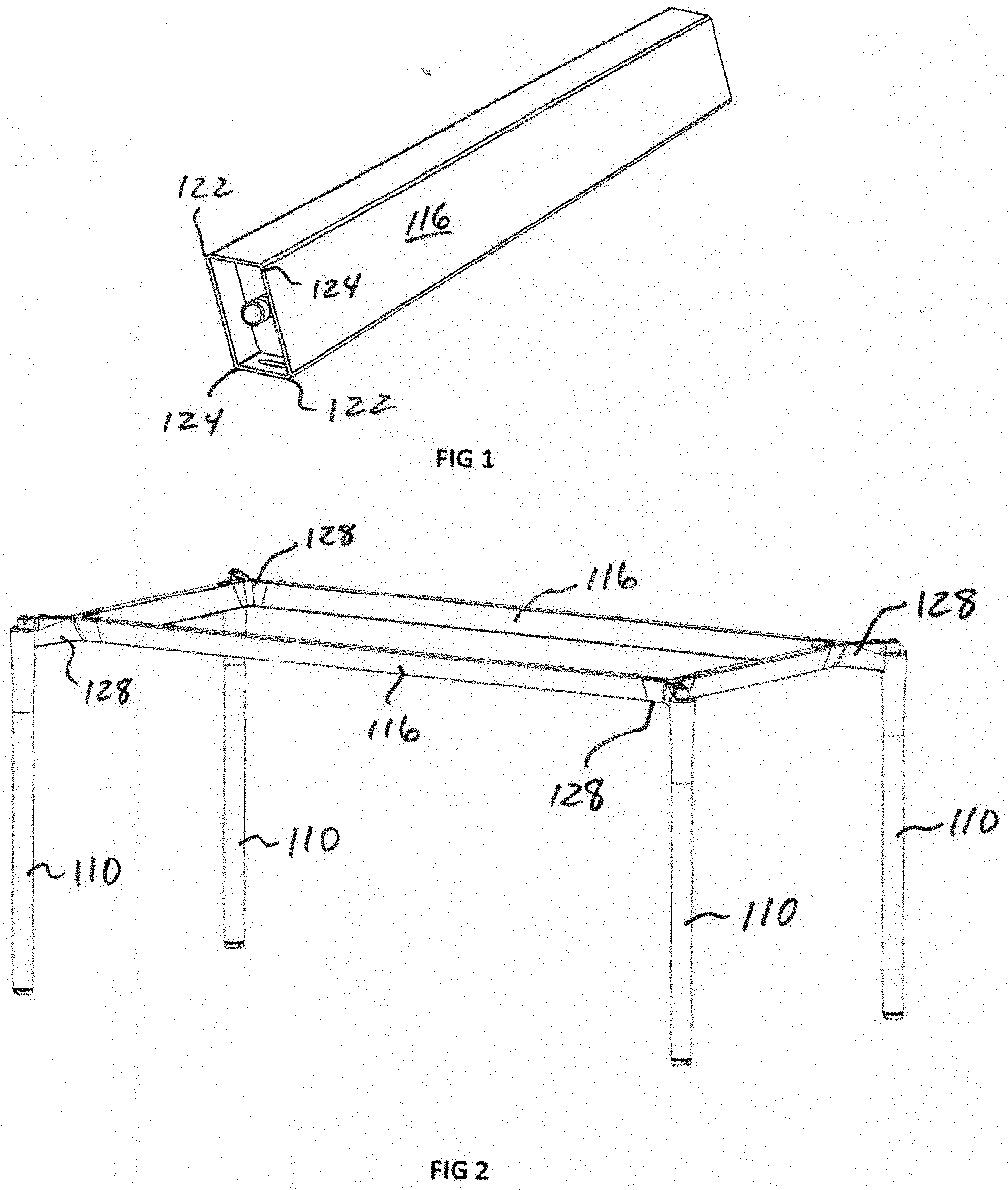
[0016] FIG. 1 is a schematic side view of a trapezoid tube weldment according to an example of the present invention.
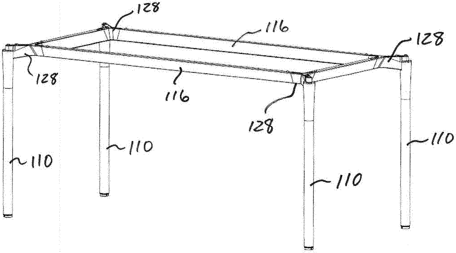
[0017] FIG. 2 is a perspective view of a modular trapezoid frame table according to an example of the present invention.
[0018] FIG. 3 is an exploded perspective view of a cam activated tabletop locking mechanism according to an example of the present invention.
[0019] FIG. 4 is a schematic bottom view of a cam activated tabletop locking mechanism according to an example of the present invention.
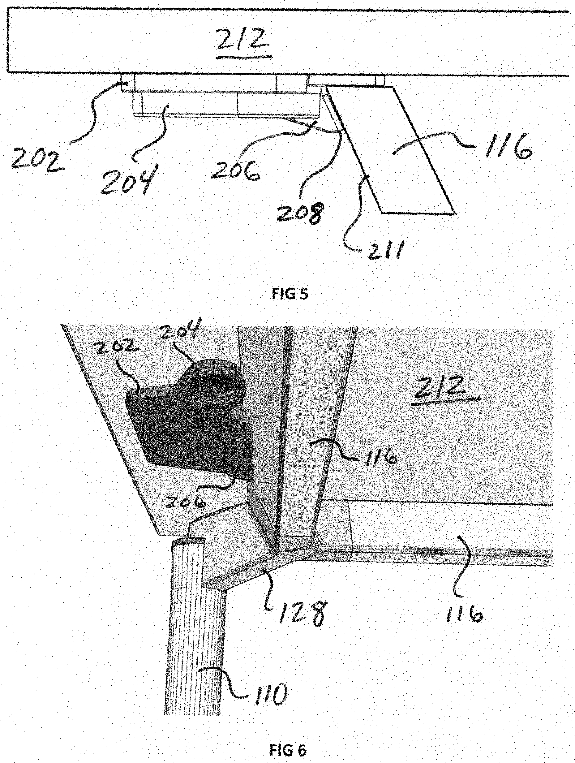
[0020] FIG. 5 is a schematic side view of a cam activated tabletop locking mechanism affixed to a table top and locked in place on trapezoid tube weldment according to an example of the present invention.
[0021] FIG. 6 is a perspective underside view of a cam activated tabletop locking mechanism affixed to a tabletop and locked in place on trapezoid tube weldment according to an example of the present invention.
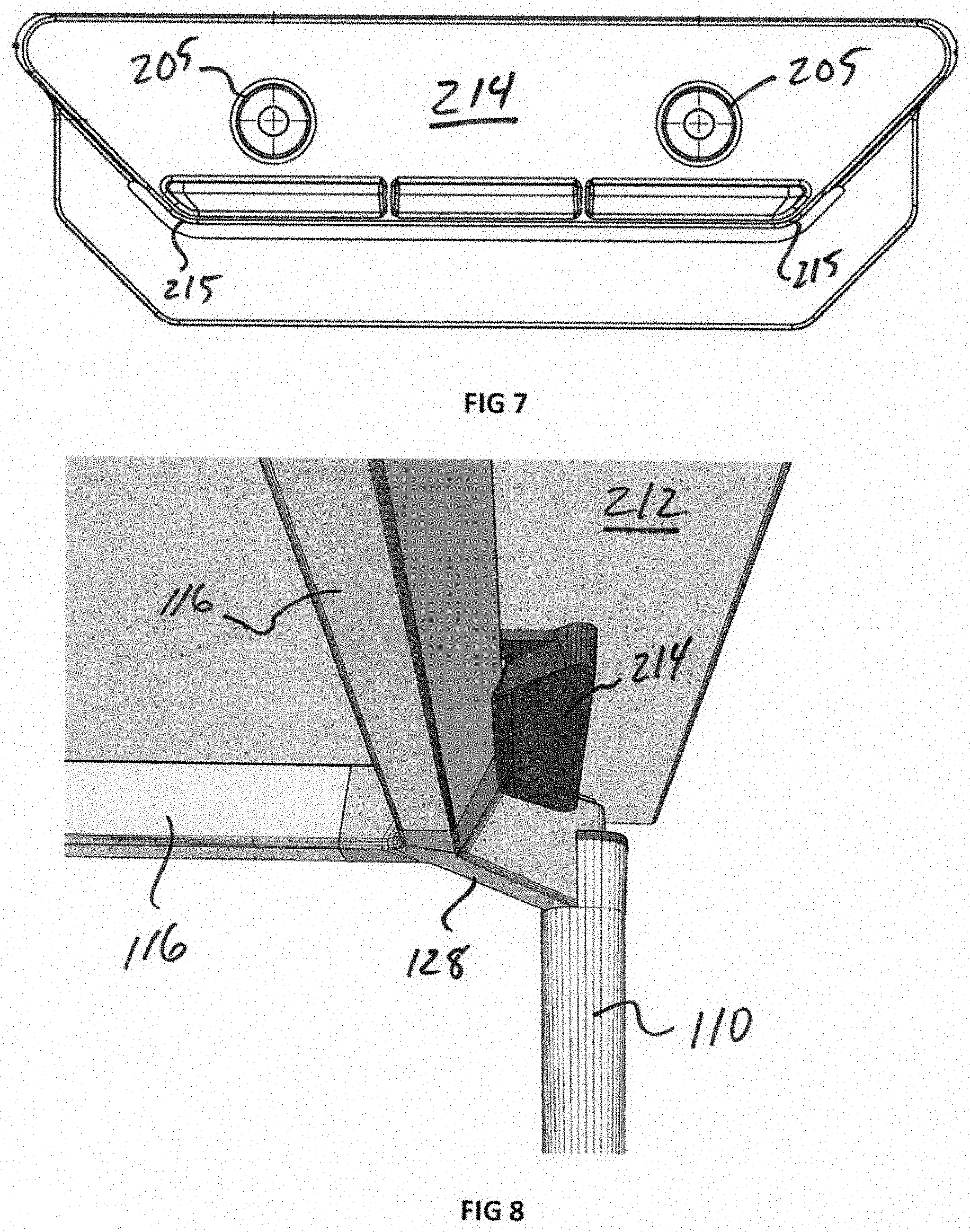
[0022] FIG. 7 is a schematic bottom view of a corner wedge block according to an example of the present invention.
[0023] FIG. 8 is a perspective underside view of a corner wedge block affixed to a tabletop and in place to locate the tabletop with respect to a table frame according to an example of the present invention.
DETAILED DESCRIPTION OF THE INVENTION
[0024] The tabletop positioning and locking assembly of the present invention is preferably used in conjunction with a modular trapezoidal frame structure, although those of skill in the art would understand that table frames with other cross sections could also be utilized and are within the scope of the present invention. However, the present invention will be described in connection with a trapezoidal tube weldment 116 as shown in FIG. 1, to construct the frame for a trapezoid frame table, shown in FIG. 2. The trapezoid tube weldments 116 are connected by corner castings 128 which are connected to legs 110 to create the table frame. As described in U.S. Utility application Ser. No. 16/058,975, many alternative table and decking configurations are contemplated by the inventors and may be utilized with the invention disclosed herein.
[0025] The angle of the trapezoid of each trapezoid tube weldment 116 is preferably 25-155-25-155, with the acute angles 122 of the trapezoid being 25 degrees and the obtuse angles 124 of the trapezoid being 155 degrees. Those of skill in the art will recognize that other angles for the trapezoid may be used to achieve the same functionality.
[0026] The trapezoidal table tube weldments provide many advantages over conventional rectangular tube weldments. In addition to a pleasing aesthetic, trapezoidal beams provide the same structural stability with a lower profile, providing more leg clearance beneath the table. Also, accessories or support beams can be dropped down into the "cone" formed by opposing trapezoids, allowing for easier securement methods compared to rectangular frame elements.
[0027] As shown in FIG. 3, the tabletop positioning and locking mechanism 200 of the present invention includes a table lock base plate 202, cam handle 204, cam slide 206, rubber tape 208 and screw 210. The legs 207 of the cam slide 206 engage the slots 203 of the base plate 202 enabling the cam slide to slide relative to the base 202, which is attached to the underside of a tabletop 212 (see FIGS. 5 and 6). The cam handle 204 rotates about the screw 210 and engages the cam slide 206 throughout its rotation.
[0028] In an open position, the cam handle 204 retracts the cam slide 206 into the base plate 202. In a closed or locked position, shown in FIG. 4, the increased radius portion of the cam handle 204 pushes the cam slide 206 towards the front edge 209 of the base plate 202. In this position, the tabletop positioning and locking mechanism engages the side of a trapezoid tube weldment, as shown in FIGS. 5 and 6.
[0029] Referring to FIG. 5, the tabletop positioning and locking mechanism 200 is shown locking the tabletop 212 to the trapezoid tube weldment 116. In this position, the cam slide 206 engages the trapezoid tube weldment 116, cushioned by the rubber tape 208. As will be readily evident, a tabletop positioning and locking mechanism on the opposite side of the table frame may be locked in a similar position on a trapezoid tube weldment 116, aligning the tabletop in the exact desired position relative to the two parallel tube weldments. Further, in this locked position, the tabletop 212 cannot be pulled upward due to the cam slide 206 engagement with the outwardly angled side 211 of the trapezoidal tube weldment 116 on both sides of the table frame. Thus, in addition to aligned with the opposite parallel members of the table frame, the table frame is also locked in position to prevent accidental removal or any movement of the tabletop until the tabletop positioning and locking mechanism is opened.
[0030] The tabletop positioning and locking mechanisms 200 of the present invention are preferably located on the outside of the table frame. In this location, the cam handle 204 can more easily be manipulated to secure or remove the tabletop 212. However, if the angle of the trapezoidal frame is reversed, so that the top of the trapezoidal frame angles inwardly rather than outwardly, providing an inwardly angled side rather than an outwardly angled side 211, the mechanisms 200 can be located on the inside of the table frame. This configuration may be desirable for certain installations or applications that desire that the locking mechanisms be hidden inside the table frame.
[0031] The baseplate 202 is preferably attached to the bottom side of a tabletop 212 with bolts that are received in inset nuts on the underside of the tabletop, with the inset nuts being located to allow for precise alignment of the tabletop with respect to a preferred table frame configuration. Additional inset nut locations may also be provided in the bottom of the tabletop so that the tabletop may be utilized in other table frame sizes and configurations. Thus, with minimal effort, the tabletop positioning and locking mechanisms may easily be moved to alternative locations that allow the tabletop to be used in reconfigurable decking systems.
[0032] As shown in FIGS. 7 and 8, a corner wedge block 214 may also be used to assist with the precise location of a tabletop relative to the table frame. As shown in FIG. 2 and discussed in detail in U.S. Utility application Ser. No. 16/058,975, the corner castings 128 provide important benefits to the inventor's modular trapezoidal frame construction. In addition to the benefits previously disclosed, the angle formed between the corner castings 128 and the trapezoid tube weldments 128 may be used to assist with the precise placement and securement of the tabletop.
[0033] Referring to FIG. 7, the corner wedge block 214 includes angled corners 215 that match the angle formed between the corner casting 128 and the trapezoid tube weldments 128. By securing the corner wedge block 214 on the underside of tabletop 212 where the trapezoid tube weldments 128 meet the corner casting 128, as shown in FIG. 8, the tabletop 212 may be further secured in place to prevent any possible movement of the tabletop relative to the table frame.
[0034] The inventors contemplate several alterations and improvements to the disclosed invention. Other alterations, variations, and combinations are possible that fall within the scope of the present invention. Although various embodiments of the present invention have been described, those skilled in the art will recognize more modifications that may be made that would nonetheless fall within the scope of the present invention. Therefore, the present invention should not be limited to the apparatus described. Instead, the scope of the present invention should be consistent with the invention claimed below.
* * * * *
D00000
D00001
D00002
D00003
D00004
XML
uspto.report is an independent third-party trademark research tool that is not affiliated, endorsed, or sponsored by the United States Patent and Trademark Office (USPTO) or any other governmental organization. The information provided by uspto.report is based on publicly available data at the time of writing and is intended for informational purposes only.
While we strive to provide accurate and up-to-date information, we do not guarantee the accuracy, completeness, reliability, or suitability of the information displayed on this site. The use of this site is at your own risk. Any reliance you place on such information is therefore strictly at your own risk.
All official trademark data, including owner information, should be verified by visiting the official USPTO website at www.uspto.gov. This site is not intended to replace professional legal advice and should not be used as a substitute for consulting with a legal professional who is knowledgeable about trademark law.