Worker Safety System
Crouthamel; L. Robert ; et al.
U.S. patent application number 16/774734 was filed with the patent office on 2020-05-28 for worker safety system. The applicant listed for this patent is Industrial Scientific Corporation. Invention is credited to Raghu Arunachalam, L. Robert Crouthamel, Benjamin Haas, Scott Jubeck, Lisa McCracken, Henry Xin.
| Application Number | 20200169945 16/774734 |
| Document ID | / |
| Family ID | 60040158 |
| Filed Date | 2020-05-28 |
View All Diagrams
| United States Patent Application | 20200169945 |
| Kind Code | A1 |
| Crouthamel; L. Robert ; et al. | May 28, 2020 |
WORKER SAFETY SYSTEM
Abstract
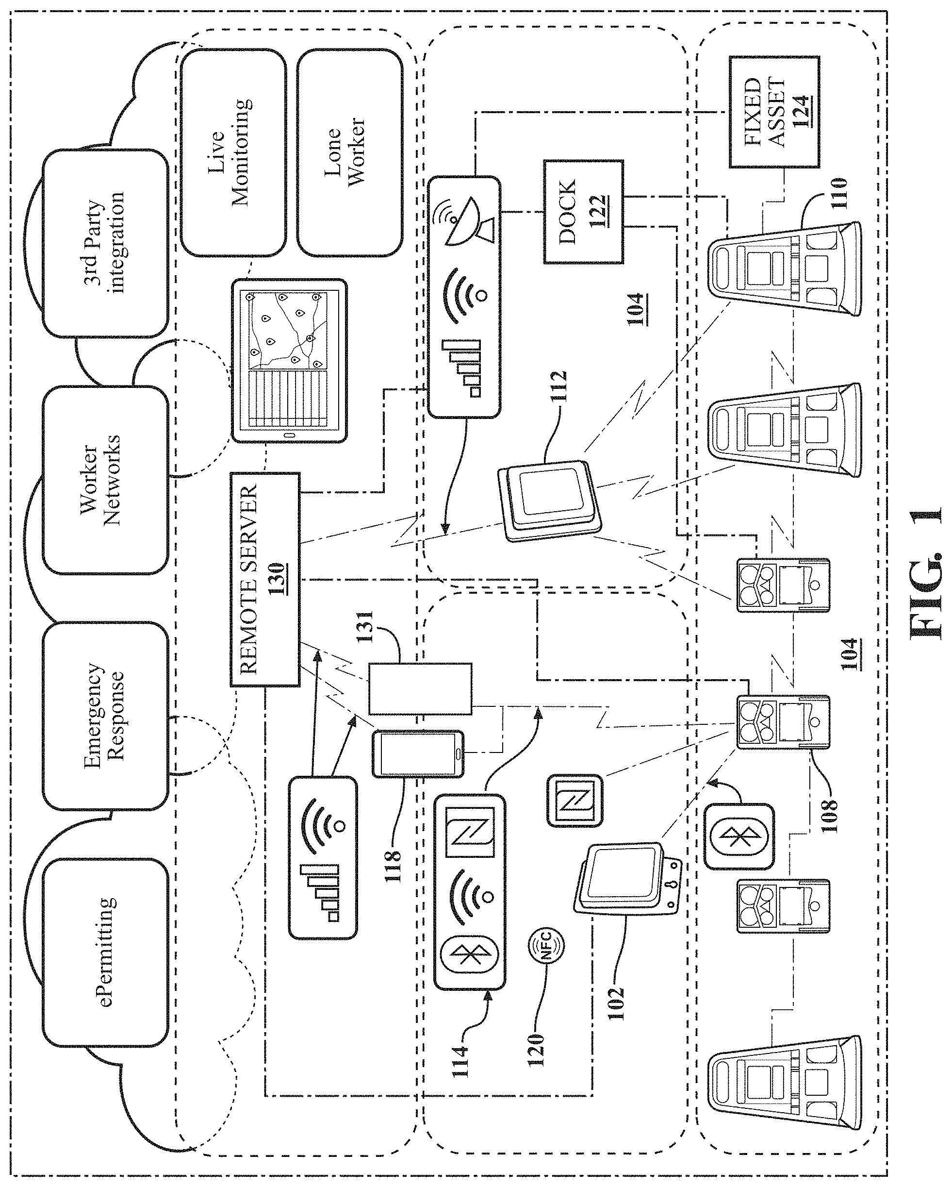
A system including a plurality of network devices including one or more worker monitoring devices and one or more area monitoring devices is provided. The plurality of network devices monitor at least one of a peer alarm, a worker biometric datum or an area environmental datum. The plurality of network devices are structured to communicate with one another in an ad-hoc wireless mesh network. A first network device of the plurality of network devices transmits the at least one peer alarm, worker biometric datum or area environmental datum for presentation on a second network device of the plurality of network devices.
| Inventors: | Crouthamel; L. Robert; (Mars, PA) ; Arunachalam; Raghu; (Pittsburgh, PA) ; Haas; Benjamin; (Monaca, PA) ; Xin; Henry; (McDonald, PA) ; McCracken; Lisa; (Oakdale, PA) ; Jubeck; Scott; (Sewickley, PA) | ||||||||||
| Applicant: |
|
||||||||||
|---|---|---|---|---|---|---|---|---|---|---|---|
| Family ID: | 60040158 | ||||||||||
| Appl. No.: | 16/774734 | ||||||||||
| Filed: | January 28, 2020 |
Related U.S. Patent Documents
| Application Number | Filing Date | Patent Number | ||
|---|---|---|---|---|
| 15491311 | Apr 19, 2017 | 10568019 | ||
| 16774734 | ||||
| 62324573 | Apr 19, 2016 | |||
| 62364935 | Jul 21, 2016 | |||
| 62385688 | Sep 9, 2016 | |||
| Current U.S. Class: | 1/1 |
| Current CPC Class: | Y02D 70/162 20180101; Y02D 30/70 20200801; Y02D 70/144 20180101; Y02D 70/1222 20180101; Y02D 70/26 20180101; Y02D 70/142 20180101; H04W 52/0235 20130101; H04W 56/0015 20130101; Y02D 70/40 20180101; Y02D 70/164 20180101; Y02D 70/166 20180101; H04W 4/80 20180201; H04W 48/10 20130101; Y02D 70/22 20180101; H04B 1/713 20130101; G06K 7/10297 20130101; H04W 84/18 20130101 |
| International Class: | H04W 48/10 20060101 H04W048/10; H04W 4/80 20060101 H04W004/80; G06K 7/10 20060101 G06K007/10; H04B 1/713 20060101 H04B001/713; H04W 52/02 20060101 H04W052/02; H04W 56/00 20060101 H04W056/00 |
Claims
1. A system comprising: a plurality of network devices comprising one or more worker monitoring devices and one or more area monitoring devices; wherein: the plurality of network devices monitor at least one of a peer alarm, a worker biometric datum or an area environmental datum; the plurality of network devices are structured to communicate with one another in an ad-hoc wireless mesh network; and a first network device of the plurality of network devices transmits, via the ad-hoc wireless mesh network, the at least one peer alarm, worker biometric datum or area environmental datum.
2. The system of claim 1, wherein receipt of the at least one peer alarm, worker biometric datum or area environmental datum at a second network device of the plurality of network devices triggers generation of a check request at the second network device, the check request comprising a request to check on an individual or an environment at a location of the first network device.
3. The system of claim 2 further comprising: a processor structured to receive a voice print of a user of the second network device at the first network device and make a determination that the user has satisfied the check request based on the voice print.
4. The system of claim 2 further comprising: a processor structured to receive an image of a user of the second network device at the first network device and make a determination that the user has satisfied the check request based on the image.
5. The system of claim 2 further comprising: a processor structured to persist the check request until making a determination that a location of the first network device is within a predetermined distance from the second network device.
6. The system of claim 5, wherein the location of the first network device or the second network device is determined based on GPS.
7. The system of claim 5, wherein the location of the first network device or the second network device is determined by location information obtained from an NFC tag read by the first network device or the second network device.
8. The system of claim 1, wherein the at least one peer alarm, worker biometric datum or area environmental datum is presented on a second network device of the plurality of network devices.
9. The system of claim 1, wherein at least one of the plurality of network devices is a real-time informational sign.
10. The system of claim 1, wherein if the area environmental datum indicates noise above a certain decibel range, the first network device is structured to transmit via at least one of a haptic transmission and a visual transmission in addition to an audible transmission.
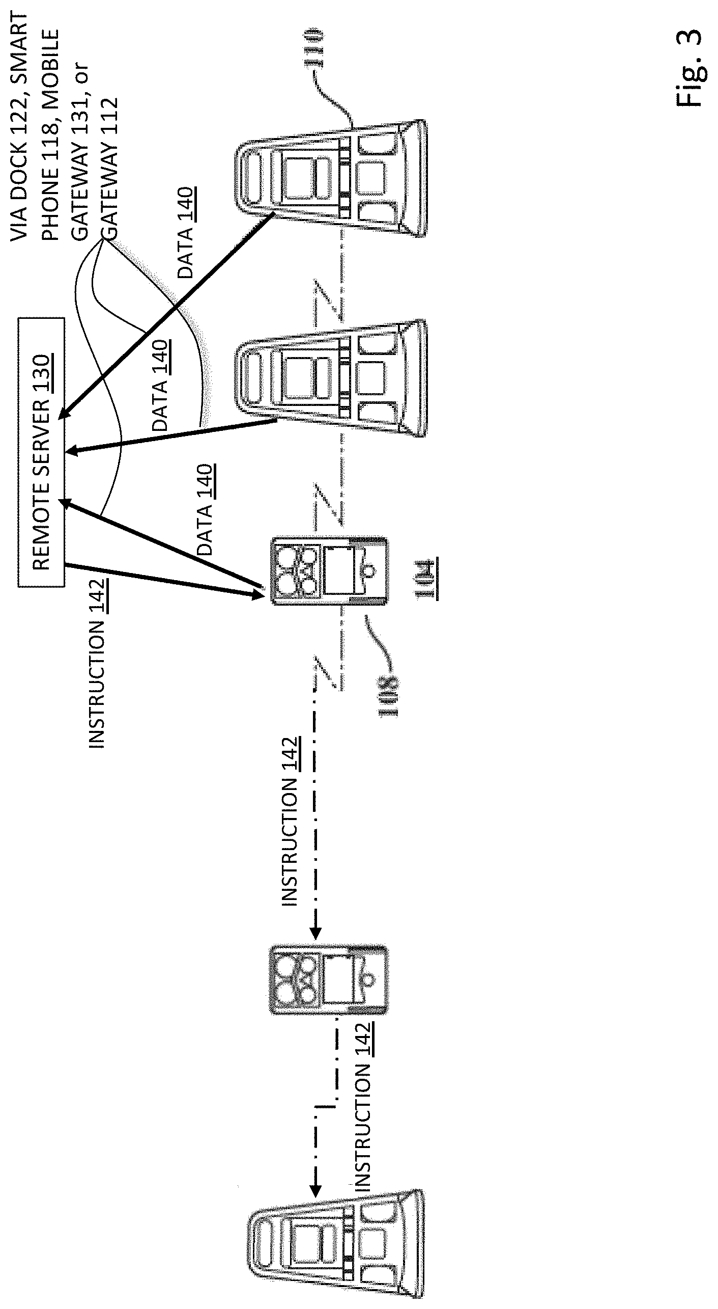
11. A system comprising: a plurality of network devices comprising a plurality of worker monitoring devices and at least one area monitoring device, wherein the plurality of network devices are structured to communicate with one another in an ad-hoc wireless mesh network and to monitor at least one of a peer alarm, a worker biometric datum or an area environmental datum; and a network gateway, wherein at least one of the plurality of network devices transmits, via the ad-hoc wireless mesh network, the at least one peer alarm, worker biometric datum or area environmental datum to a remote computer through the network gateway.
12. The system of claim 11, wherein the remote computer transmits instructions or information to selected devices of the plurality of network devices based on the at least one peer alarm, worker biometric datum or area environmental datum.
13. The system of claim 11, wherein at least one of the plurality of network devices is a real-time informational sign.
14. The system of claim 11, wherein the remote computer is structured to control at least one of the plurality of network devices.
15. The system of claim 14, wherein if the peer alarm indicates an area should be evacuated, the remote computer is triggered to take control of the at least one of the plurality of network devices.
16. The system of claim 15, wherein the at least one of the plurality of network devices is a drone-mounted or a vehicle-mounted environmental sensing device.
17. A system comprising: a plurality of network devices comprising one or more worker monitoring devices and one or more area monitoring devices; wherein: the plurality of network devices monitor at least one of a peer alarm, a worker biometric datum or an area environmental datum; the plurality of network devices are structured to communicate with one another in an ad-hoc wireless mesh network; at least one network device of the plurality of network devices transmits, via the ad-hoc wireless mesh network, the at least one peer alarm, worker biometric datum or area environmental datum to a remote-networked device; and the remote-networked device is structured to further transmit the at least one peer alarm, worker biometric datum or area environmental datum to a remote computer.
18. The system of claim 17, wherein the remote computer transmits instructions or information to selected devices of the plurality of network devices based on the at least one peer alarm, worker biometric datum or area environmental datum.
19. The system of claim 17, wherein at least one of the plurality of network devices is a real-time informational sign.
20. The system of claim 17, wherein the remote computer is structured to control at least one of the plurality of network devices.
21. The system of claim 20, wherein if the peer alarm indicates an area should be evacuated, the remote computer is triggered to take control of the at least one of the plurality of network devices.
22. The system of claim 17 further comprising: an NFC tag programmed with assignment information, wherein the assignment information is at least one of a location assignment for the NFC tag and an instrument operator assignment for the NFC tag; wherein receipt of the assignment information at a safety device triggers activation of a function of the safety device.
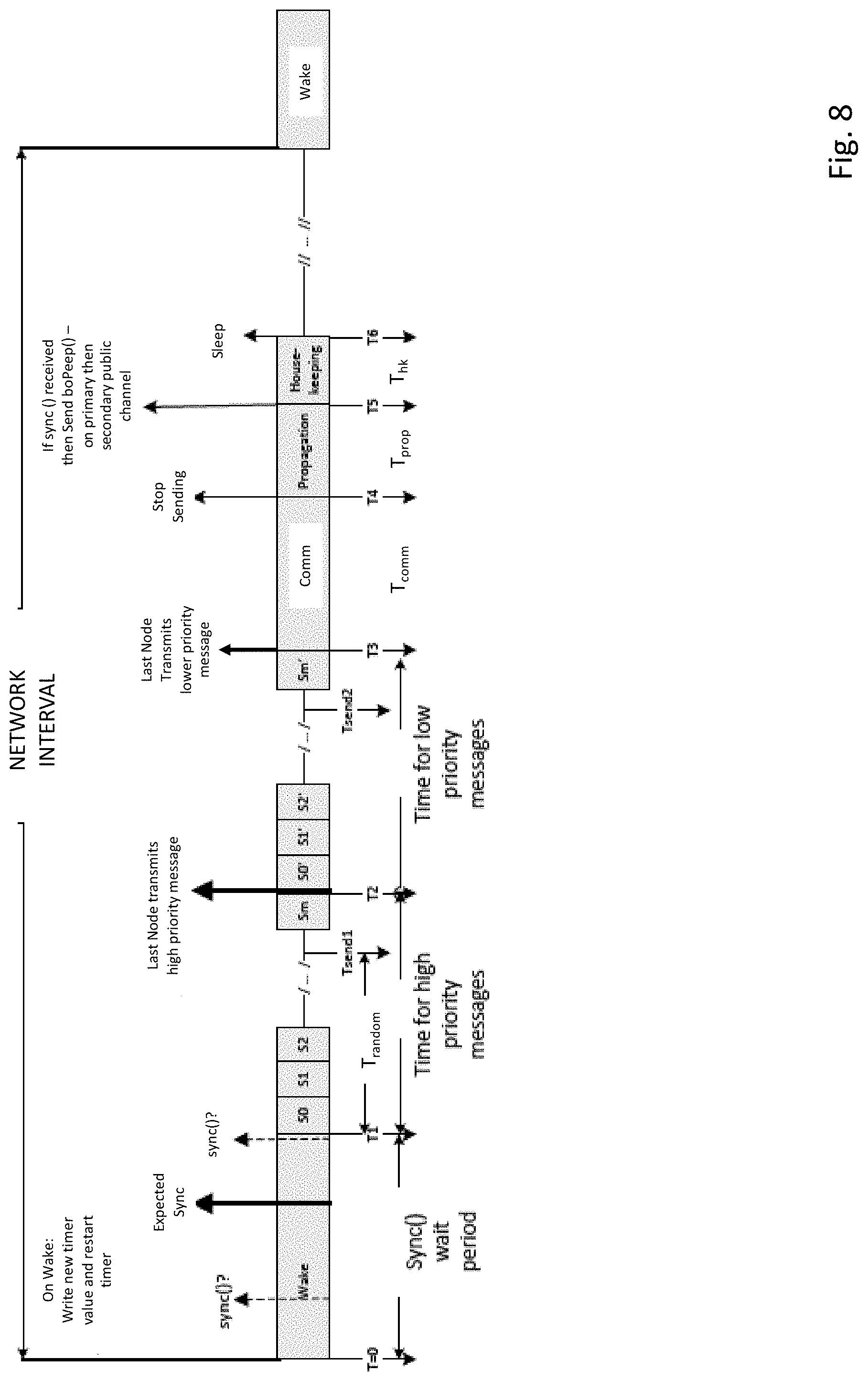
23. The system of claim 17, wherein the plurality of network devices are part of a plurality of nodes of the ad-hoc wireless mesh network, wherein: the plurality of nodes comprises a single leader node and a plurality of follower nodes; the single leader node transmits a sync message to the plurality of follower nodes indicating a beginning of a network interval having a transmission period and a sleep period; the single leader node and the plurality of follower nodes transmit information during the transmission period and do not transmit information during the sleep period; and during a predetermined time of the transmission period, each of the plurality of follower nodes that received the sync message transmits a message advertising one or more properties of the single leader node.
24. A method comprising: monitoring, via at least one network device of a plurality of network devices comprising one or more worker monitoring devices and one or more area monitoring devices, at least one of a peer alarm, a worker biometric datum or an area environmental datum, wherein each network device of the plurality is structured to communicate via an ad-hoc wireless mesh network; and transmitting, by a first network device of the plurality of network devices via the ad-hoc wireless mesh network, the at least one peer alarm, worker biometric datum or area environmental datum.
25. The method of claim 24 further comprising: receiving, at a second network device of the plurality of network devices, the at least one peer alarm, worker biometric datum or area environmental datum.
26. The method of claim 25 further comprising: in response to receiving the at least one peer alarm, worker biometric datum or area environmental datum at the second network device, generating a check request comprising a request to check on an individual or an environment at a location of the first network device.
27. The method of claim 26 further comprising: receiving, by a processor, a voice print of a user of the second network device at the first network device; and determining via the processor that the user has satisfied the check request based on the voice print.
28. The method of claim 26 further comprising: receiving, by a processor, an image of a user of the second network device at the first network device; and determining via the processor that the user has satisfied the check request based on the image.
29. A method comprising: monitoring, by at least one network device of a plurality of network devices comprising one or more worker monitoring devices and one or more area monitoring devices, at least one of a peer alarm, a worker biometric datum or an area environmental datum, wherein each network device of the plurality is structured to communicate via an ad-hoc wireless mesh network; and transmitting, by the at least one network device, via the ad-hoc wireless mesh network, the at least one peer alarm, worker biometric datum or area environmental datum to a remote computer through a network gateway.
30. The method of claim 29 further comprising: transmitting, via the remote computer, instructions or information to selected devices of the plurality of network devices based on the at least one peer alarm, worker biometric datum or area environmental datum.
31. The method of claim 29, wherein at least one of the plurality of network devices is a real-time informational sign.
32. The method of claim 29 further comprising: controlling, via the remote computer, at least one of the plurality of network devices.
33. The method of claim 32 further comprising: triggering the remote computer to take control of the at least one of the plurality of network devices.
Description
CLAIM TO PRIORITY
[0001] This application is a continuation of U.S. Ser. No. 15/491,311, filed Apr. 19, 2017 (ISCI-0039-U01), which is hereby incorporated by reference in its entirety.
[0002] U.S. Ser. No. 15/491,311 claims the benefit of the following provisional applications, each of which is hereby incorporated by reference in its entirety: U.S. Ser. No. 62/324,573, filed Apr. 19, 2016 (ISCI-0026-P01); U.S. Ser. No. 62/364,935, filed Jul. 21, 2016 (ISCI-0027-P01); and U.S. Ser. No. 62/385,688, filed Sep. 9, 2016 (ISCI-0037-P01).
[0003] U.S. Ser. No. 15/491,311 is also related to the following U.S. patents and patent applications each of which is incorporated by reference herein in its entirety: U.S. Pat. No. 9,000,910 filed on Jun. 24, 2011 (ISCI-0020-U01), U.S. Pat. No. 9,575,043 filed Apr. 1, 2015 (ISCI-0020-U01-001), U.S. patent application Ser. No. 15/376,823, filed Dec. 13, 2016 (ISCI-0020-U01-001-001), U.S. Pat. No. 6,338,266 filed Apr. 5, 2000 (ISCI-0005-U01), U.S. Pat. No. 6,435,003 filed Nov. 8, 2001 (ISCI-0005-U01-V01), U.S. Pat. No. 6,888,467 filed Dec. 10, 2002 (ISCI-0014-U01), U.S. Pat. No. 6,742,382 filed Dec. 24, 2002 (ISCI-0015-U01), U.S. Pat. No. 6,442,639 filed Apr. 19, 2000 (ISCI-0006-U01), U.S. Pat. No. 7,007,542 filed Jun. 16, 2003 (ISCI-0009-U01-V01), and U.S. Patent Application Serial No. 2016/0209386, entitled MODULAR GAS MONITORING SYSTEM and filed on Jan. 15, 2016 (ISCI-0023-U01).
BACKGROUND
Field
[0004] This disclosure relates to ad hoc, mesh wireless networks for communication between safety instruments, communication approaches from instruments to a remote location, and end use applications that use data from the instruments.
SUMMARY
[0005] In an aspect, a tangible article of manufacture having instructions stored thereon that, when executed, causes a machine to perform operations for tracking an operator and operator status using a safety device, the operations comprising: programming a plurality of NFC tags with assignment information, wherein the assignment information is at least one of a location assignment for NFC tags being placed at particular locations and an instrument operator assignment for tags distributed to multi-gas detection instrument operators; receiving temporary assignment information at the safety device when an NFC radio of the safety device is brought in proximity to at least one of the plurality of NFC tags; and tagging safety device data with the temporary assignment information. In this aspect and others disclosed herein, the programming of the plurality of NFC tags is not required. In fact, pre-programmed NFC tags may be purchase for use in the systems and methods disclosed herein. The operations further include storing the tagged safety device data in a safety device data log. The operations further include wirelessly transmitting the tagged safety device data to at least one of a cloud-based or other remote log and a second device. The operations further include removing the temporary assignment by bringing the safety device into proximity to the at least one NFC tag again. The safety device is a multi-gas detection instrument, a gas detection instrument, or at least one of a respirator, a harness, a lighting device, a fall arrest device, a thermal detector, a flame detector, and a chemical, biological, radiological, nuclear, and explosives (CBRNE) detector.
[0006] In an aspect, a tangible article of manufacture having instructions stored thereon that, when executed, causes a machine to perform operations for tracking an operator and operator status using a safety device, the operations comprising: programming a plurality of NFC tags with assignment information, wherein the assignment information is at least one of a location assignment for NFC tags being placed at particular locations and an instrument operator assignment for tags distributed to safety device operators; receiving assignment information at the safety device when an NFC radio of the safety device is brought in proximity to at least one of the plurality of NFC tags; and triggering one or more of an alarm and a message upon detection of a safety event, wherein the trigger is filtered by the temporary assignment information. The assignment tags for identifying individuals are programmed with information including one or more of a name, a size, a weight, a typical work location, a job function, a typical instrument used, a pre-existing concern, a language known, a prior alarm, a prior gas event, a prior safety event, and a prior message. The assignment tags for identifying locations are programmed with information including one or more of a location within a space, a GPS location, an equipment at the location, a fuel source at the location, a known hazard at the location, a typical gas concentration for the location, an environmental condition for the location, a recent gas event, a recent man down alarm, a recent alarm, and a recent message. Triggering further comprises applying a filter based on the assignment tag's programmed information. The safety device is at least one of a multi-gas detection instrument, a gas detection instrument, a respirator, a harness, a lighting device, a fall arrest device, a thermal detector, a flame detector, and a chemical, biological, radiological, nuclear, and explosives (CBRNE) detector. The safety event is a gas event.
[0007] In an aspect, an industrial safety monitoring system includes a personal NFC tag assigned to a worker, wherein the tag assigned to the worker comprises information of the identity of the worker; a plurality of location NFC tags assigned to locations, each location tag placed in a location comprising information of the location in which the location tag is placed; at least one portable environmental sensing device detecting data of an environmental parameter, the at least one portable environmental sensing device configured to (i) read the personal NFC tag and to transmit the information of the identity of the worker using the sensing device, and (ii) read at least one of the plurality of location NFC tags and to transmit the information of the location of a location tag read by the at least one portable environmental sensing device; and at least one processor in communication with the at least one portable environmental sensing device and receiving from the at least one portable environmental sensing device (i) detected data of an environmental parameter, (ii) the information of the identity of the worker using the at least one portable environmental sensing device, and (iii) information of the location of a location tag read by the at least one portable environmental sensing device, wherein the at least one processor is programmed to determine an environmental parameter of the worker using the sensing device and the location of the determined environmental parameter. The system further includes a memory in communication with the at least one portable environmental sensing device that stores the detected data and the information in a portable environmental sensing device data log. The system further includes a wireless transmitter that transmits the detected data and the information to at least one of a cloud-based or other remote log and a second portable environmental sensing device. The assignment tags for identifying workers are programmed with information including one or more of a name, a size, a weight, a typical work location, a job function, a typical instrument used, a pre-existing concern, a language known, a prior alarm, a prior gas event, a prior safety event, and a prior message. The assignment tags for identifying locations are programmed with information including one or more of a location within a space, a GPS location, an equipment at the location, a fuel source at the location, a known hazard at the location, a typical gas concentration for the location, an environmental condition for the location, a recent gas event, a recent man down alarm, a recent alarm, and a recent message. The at least one portable environmental sensing device is at least one of a multi-gas detection instrument, a gas detection instrument, a respirator, a harness, a lighting device, a fall arrest device, a thermal detector, a flame detector, and a chemical, biological, radiological, nuclear, and explosives (CBRNE) detector.
[0008] In an aspect, a tangible article of manufacture having instructions stored thereon that, when executed, causes a machine to perform operations for tracking an operator and operator status using a safety device, the operations comprising: programming a plurality of NFC tags with assignment information, wherein the assignment information is at least one of a location assignment for NFC tags being placed at particular locations and an instrument operator assignment for tags distributed to safety device operators; receiving assignment information at the safety device when an NFC radio of the safety device is brought in proximity to at least one of the plurality of NFC tags; and triggering an activation of a function of the safety device based on the temporary assignment information.
[0009] In an aspect, A tangible article of manufacture having instructions stored thereon that, when executed, causes a machine to perform operations for tracking an operator and operator status using a safety device, the operations comprising: programming a plurality of NFC tags with assignment information, wherein the assignment information is at least one of a location assignment for NFC tags being placed at particular locations and an instrument operator assignment for tags distributed to safety device operators; receiving assignment information at the safety device when an NFC radio of the safety device is brought in proximity to at least one of the plurality of NFC tags; and triggering a modification of a setting of the safety device based on the temporary assignment information.
[0010] In an aspect, a tangible article of manufacture having instructions stored thereon that, when executed, causes a machine to perform operations for tracking an operator and operator status using a safety device, the operations comprising: programming a plurality of NFC tags with assignment information, wherein the assignment information is at least one of a location assignment for NFC tags being placed at particular locations and an instrument operator assignment for tags distributed to safety device operators; receiving assignment information at the safety device when an NFC radio of the safety device is brought in proximity to at least one of the plurality of NFC tags; triggering one or more of an alarm and a message upon detection of a safety event, wherein the triggered alarm or message is filtered by the temporary assignment information; and communicating the triggered alarm or message to at least one other safety device in a mesh network with features as described herein for presentation on the second safety device. The assignment tags for identifying individuals are programmed with information including one or more of a name, a size, a weight, a typical work location, a job function, a typical instrument used, a pre-existing concern, a language known, a prior alarm, a prior gas event, a prior safety event, and a prior message. The assignment tags for identifying locations are programmed with information including one or more of a location within a space, a GPS location, an equipment at the location, a fuel source at the location, a known hazard at the location, a typical gas concentration for the location, an environmental condition for the location, a recent gas event, a recent man down alarm, a recent alarm, and a recent message. Triggering further comprises applying a filter based on the assignment tag's programmed information. The safety device is at least one of a multi-gas detection instrument and a gas detection instrument. The safety device is at least one of a respirator, a harness, a lighting device, a fall arrest device, a thermal detector, a flame detector, and a chemical, biological, radiological, nuclear, and explosives (CBRNE) detector. The safety event is a gas event.
[0011] In an aspect, a tangible article of manufacture having instructions stored thereon that, when executed, causes a machine to perform operations for tracking an operator and operator status using a safety device, the operations comprising: programming a plurality of NFC tags with assignment information, wherein the assignment information is at least one of a location assignment for NFC tags being placed at particular locations and an instrument operator assignment for tags distributed to safety device operators; receiving assignment information at the safety device when an NFC radio of the safety device is brought in proximity to at least one of the plurality of NFC tags; triggering a modification of a setting of the safety device based on the temporary assignment information; and communicating the modified setting to at least one other safety device in a mesh network with features as described herein for modification of a setting of the second safety device.
[0012] In an aspect, an alerting system includes a safety device comprising a GPS system; and an interface configured to: transmit the location of the safety device based on data from the GPS system to a remote server; receive alert information from the remote server in response to the remote server determining the location of the safety device corresponds to a hazardous location, wherein the remote server determines the hazardous location based on a condition detected from one or more of the safety device, a second safety device in an area within a pre-defined distance from the safety device, an area monitor, and third party data; and communicate the alert information to one or more devices in a mesh network with features as described herein joined by the safety device. The interface is a component of the safety device, a network gateway, or a smart phone.
[0013] In an aspect, an alerting system includes a safety device configured to read at least one of a plurality of location NFC tags comprising information regarding the location in which it is placed; and an interface configured to: transmit the location of the safety device based on the information from the location NFC tag to a remote server; and receive alert information from the remote server in response to the remote server determining the location of the safety device corresponds to a hazardous location, wherein the remote server determines the hazardous location based on a condition detected from one or more of the safety device, a second safety device in the location, an area monitor in the location, and third party data related to the location. The interface is a component of the safety device, a network gateway, or a smart phone. The interface is further configured to communicate the alert information to one or more devices in a mesh network joined by the safety device.
[0014] In an aspect, a computer-implemented method for providing real time locating and gas exposure monitoring includes receiving, by a computer processor, a first gas reading and a first location from a first device; receiving, by the computer processor, a second location from a second device; and transmitting one or more of an alert and the gas reading to the second device when the second location is within a predetermined distance from the first location and the gas reading exceeds a threshold, wherein the second device relays the alert and/or the gas reading to at least one peer device in a mesh network with features as described herein joined by the second device.
[0015] In an aspect, a computer-implemented method for providing real time locating and gas exposure monitoring includes receiving, by a computer processor, a first gas reading and a first location from a first device, wherein the first location is read from a location NFC tag in the location by the first device; receiving, by the computer processor, a second location from a second device; and transmitting one or more of an alert and the gas reading to the second device when the second location is within a predetermined distance from the first location and the gas reading exceeds a threshold. The second device relays the alert and/or the gas reading to at least one peer device in a mesh network with features as described herein joined by the second device.
[0016] In an aspect, a computer-implemented method for providing real time locating and gas exposure monitoring includes receiving, by a computer processor, a first safety event and a first location from a first device; receiving, by the computer processor, a second location from a second device; and transmitting an alert and the safety event to the second device when the second location is within a predetermined distance from the first location, wherein the second device relays the alert and/or the gas reading to at least one peer device in a mesh network with features as described herein joined by the second device.
[0017] In an aspect, a computer-implemented method for providing real time locating and gas exposure monitoring includes receiving, by a computer processor, a first safety event and a first location from a first device, wherein the first location is read from a location NFC tag in the location by the first device; receiving, by the computer processor, a second location from a second device; and transmitting an alert and the safety event to the second device when the second location is within a predetermined distance from the first location. The second device relays the alert and/or the gas reading to at least one peer device in a mesh network with features as described herein joined by the second device.
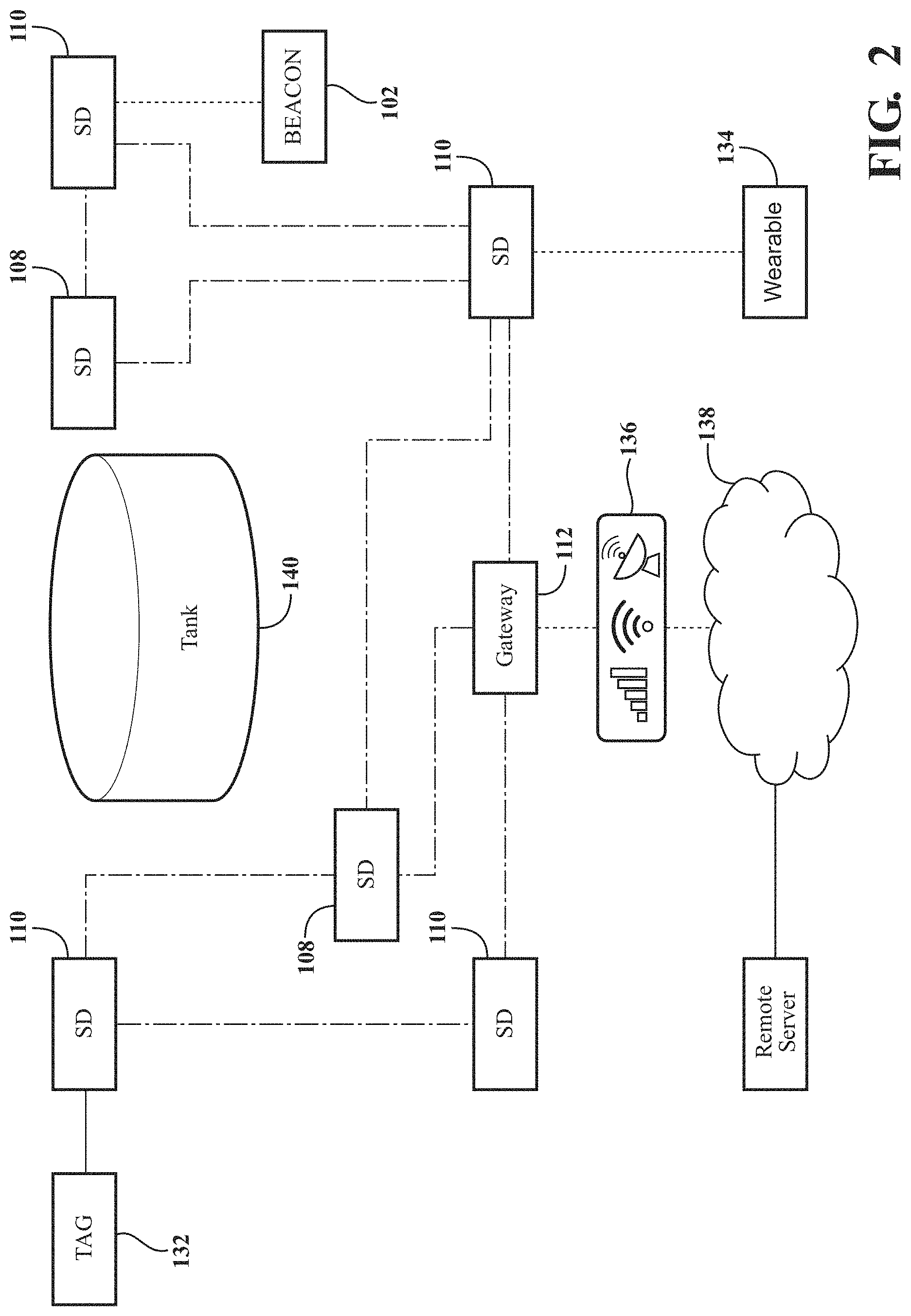
[0018] In an aspect, a system includes a plurality of portable environmental sensing devices in a work area adapted to communicate with one another in a mesh network with features as described herein; and a communications facility to transmit data from at least one of the plurality of portable environmental sensing devices to a remote computer, the remote computer configured to monitor at least one of a hazardous condition and an activation of a panic button in the work area based on data from the at least one of the plurality of portable environmental sensing devices, wherein the remote computer is configured to: receive, from the at least one portable environmental sensing device, an alarm related to the hazardous condition or activation of panic button, and transmit to any of the portable environmental sensing devices an instruction to be propagated throughout the mesh network. The instruction is a request to check the safety of a user of the at least one portable environmental sensing device, an evacuation instruction, a risk mitigation instruction, or the like. The remote computer is further configured to display the location of the portable environmental sensing devices in a map of the work area, wherein the remote computer transmits the map for display on the any of the portable environmental sensing devices. The data is sensed gas data, wherein the hazardous condition is based on the sensed gas data exceeding a threshold and the remote computer is further configured to display the sensed gas data in a map of the work area. A size of the representation of the gas data is proportional to the gas level. The remote computer is further configured to request an emergency response at the location of the at least one portable environmental sensing device.
[0019] In an aspect, a system for providing an ad-hoc mesh network with features as described herein for an eyewash station includes a sensor disposed within the eyewash station to monitor a condition, the sensor adapted to communicate with nodes in a mesh network; and a digital sign, wherein the digital sign is adapted to receive data related to the condition from the sensor through the mesh network for presentation.
[0020] In an aspect, a system for providing an ad-hoc mesh network with features as described herein for an eyewash station includes a sensor disposed within the eyewash station to monitor a condition, the sensor adapted to communicate with nodes in a mesh network; and a device in the mesh network configured to receive the communication from the sensor related to the condition and generate an alarm based on the condition meeting a threshold or criteria. The system further includes a digital sign in the mesh network, wherein the digital sign is adapted to receive the alarm from the device through the mesh network for presentation. The device in the mesh network is further configured to obtain one or more of a worker biometric datum and an area environmental datum. The device in the mesh network is further configured to transmit the alarm to a remote computer. The device in the mesh network is further configured to obtain an inventory of potential hazards from an NFC tag in the area near the eyewash station when an NFC radio of the device is brought in proximity to the NFC tag. A secondary alarm is generated based on at least one item in the inventory.
[0021] In an aspect, a method of sensing a root cause or symptom of death or injury of a worker on a worksite includes obtaining sensor data from one or more body worn sensors attached to the body of the worker, wherein the sensor data relates to one or more physiological and behavioral effects of the root cause of worker death or injury; analyzing the sensor data to identify a safety issue; and modifying an authorization level of the worker when the analyzed sensor data identifies a presence of the safety issue, wherein the authorization level is stored on a device of the worker.
[0022] In an aspect, a method of sensing a root cause or symptom of death or injury of a worker on a worksite includes obtaining sensor data from one or more body worn sensors attached to the body of the worker, wherein the sensor data relates to one or more physiological and behavioral effects of the root cause of worker death or injury; analyzing the sensor data to identify a safety issue; and when the analyzed sensor data identifies a presence of the safety issue, communicating the safety issue to a safety device of the worker for presentation on the safety device. The method further includes communicating the safety issue to a second safety device of a second worker for presentation, wherein the safety device and the second safety device are peers in a mesh network.
[0023] In an aspect, a method of sensing a root cause or symptom of death or injury of a worker on a worksite includes obtaining sensor data from one or more body worn sensors attached to the body of the worker, wherein the sensor data relates to one or more physiological and behavioral effects of the root cause of worker death or injury; analyzing the sensor data to identify a safety issue; and when the analyzed sensor data identifies a presence of the safety issue, communicating a request to check-in with the worker to a safety device of a second worker.
[0024] In an aspect, a system for providing a low-power ad-hoc mesh network with features as described herein for a remote jobsite includes a plurality of network devices comprising one or more worker monitoring devices and one or more area monitoring devices, wherein the network devices monitor at least one of a peer alarm, a worker biometric datum or an area environmental datum; and the network devices adapted to communicate with one another in a mesh network without a central network controller; wherein a first network device of the plurality of network devices transmits the peer alarm, the worker biometric datum or the area environmental datum to a second network device of the plurality of network devices for presentation on the second network device.
[0025] In an aspect, a system includes a plurality of network devices comprising one or more worker monitoring devices and one or more area monitoring devices, wherein the network devices monitor at least one of a peer alarm, a worker biometric datum or an area environmental datum, the network devices adapted to communicate with one another in a mesh network with features as described herein; and a network gateway, wherein the plurality of network devices transmits the peer alarm, the worker biometric datum or the area environmental datum to a remote computer through the gateway.
[0026] In an aspect, a system includes a plurality of network devices comprising one or more worker monitoring devices and one or more area monitoring devices, wherein the network devices monitor at least one of a peer alarm, a worker biometric datum or an area environmental datum, the network devices adapted to communicate with one another in a mesh network with features as described herein; and a device interface for a remote-networked device, wherein the plurality of network devices transmits the peer alarm, the worker biometric datum or the area environmental datum to the remote-networked device, wherein the remote-networked device is configured to further transmit the peer alarm, the worker biometric datum or the area environmental datum to a remote computer.
[0027] In an aspect, a method of sensing a root cause or symptom of death or injury of a worker on a worksite includes obtaining sensor data from one or more body worn sensors attached to the body of the worker, wherein the sensor data relates to one or more physiological and behavioral effects of the root cause of worker death or injury; analyzing the sensor data to identify a safety issue; and providing an alert to the worker or a third party when the analyzed sensor data identifies a presence of the safety issue. The alert is transmitted from the one or more body-worn sensors to a remote location via a network connection. The alert is transmitted directly from the one or more body-worn sensors to one or more workers located on the worksite. The step of analyzing the sensor data occurs within the body worn sensor. The sensor data is transmitted via a wireless network from the body-worn sensor to a remote location for analysis of the sensor data. The remote location communicates with the body-worn sensor to alert the worker wearing the body-worn sensor when the analyzed sensor data identifies the presence of the safety issue. The remote location communicates with the third party on the worksite to alert the third party that the analyzed sensor data indicates the presence of the safety issue related to the worker wearing the body-worn sensor. The physiological effects include an effect on at least one of ECG, heart rate, blood pressure, breathing rate, skin temperature, posture, activity, accelerometry, blood pressure, pulse, body odors, blood alcohol level, glucose levels, and oxygen saturation. The behavioral effects include an effect on at least one of gait, walking patterns, posture, eye movements, pupil size, motion patterns, noises, and removal of the sensor from the person before a prescribed time. The body-worn sensors comprise one or more of a heart rate sensor, blood pressure sensor, gait detection sensor, olfactory sensor, galvanic skin response sensor, proximity sensor, accelerometer, eye tracking sensor, image sensor, microphone, infrared sensor, gas sensor, capacitive sensor, fingerprint sensor, networking signal detector, and location detector. The method further includes the step of storing the sensor data and comparing current sensor data to stored sensor data to determine a variance indicating a safety issue. The method further includes the step of storing typical sensor data from a plurality of workers and comparing current sensor data for the worker to stored sensor data for the plurality of workers to determine a variance indicating a safety issue. The method further includes the step of preventing the worker from accessing a system after identifying a safety issue. The method further includes the step of suggesting a behavior change to the worker to avoid a safety issue.
[0028] In an aspect, a system for providing a low-power ad-hoc mesh network for a remote jobsite includes a plurality of network devices comprising one or more sensing devices and one or more area monitoring devices, wherein the network devices monitor at least one of a peer alarm, a worker biometric datum or an area environmental datum; the network devices adapted to communicate with one another in a mesh network with features as described herein; wherein a first network device of the plurality of network devices transmits the peer alarm, the worker biometric datum or the area environmental datum to a second network device of the plurality of network devices for presentation on the second network device.
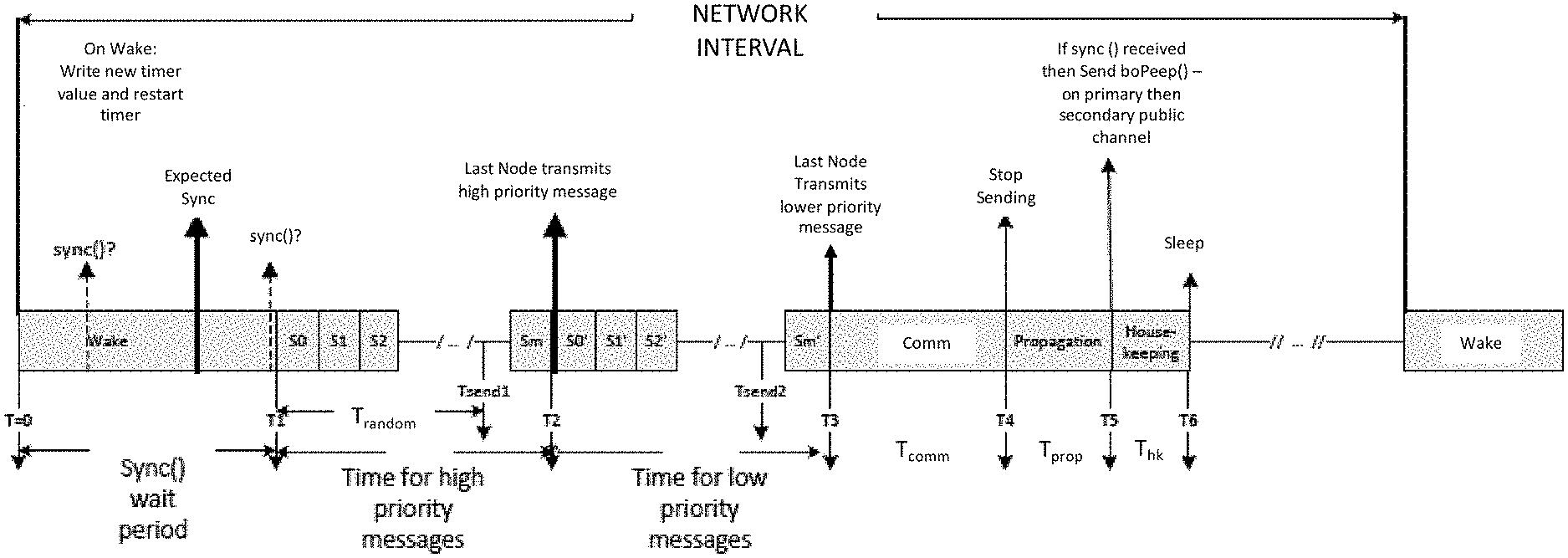
[0029] In an aspect, a network for connecting a plurality of network nodes with features as described herein includes a leader node; and a plurality of follower nodes, wherein the leader node transmits a sync message to the plurality of follower nodes indicating a beginning of a network interval, wherein the leader node and the plurality of follower nodes transmit information during a transmission period of the network interval and do not transmit information during a sleep period of the network interval, the leader node and plurality of follower nodes using less power in the sleep period than the transmission period, the plurality of follower nodes each comprising a timer, the timer adapted to time the transmission period and sleep period of a plurality of future network intervals in an absence of continued receipt of the sync message from the leader node during the plurality of future network intervals. When any of the plurality of follower nodes receive a sync message, the follower node transmits a message advertising one or more properties of the leader node during a predetermined period of the network interval. The one or more properties of the leader node includes at least one of a channel hopping sequence and a total number of the network nodes on the network. When any one of the plurality of follower nodes fails to receive a receive a sync message from the leader node, the follower node refrains from transmitting a message advertising a property of the leader node during the network interval. Follower nodes each comprise a counter for tracking the receipt of sync message from the leader. The counter is incremented when a sync message is received and decremented when a sync message is not received. When the counter of any one of the follower nodes reaches a predetermined value, the follower node initiates a procedure for finding a new leader node. When the timer is further adapted to time an expected receipt of future sync messages of future network intervals and when an actual receipt of the future sync message deviates from an expected receipt of the future sync message by a predetermined amount of time for a predetermined number of network intervals, the follower node adjusts the timer to more closely correspond with the actual receipt of the future sync message. The sync message includes data indicating the number of network nodes in the network. The length of the transmission period is determined by the number of network nodes in the network. The network nodes are environmental sensing devices. The information is assigned by reading an NFC tag. The information relates to a concentration of gas or an environmental attribute. The network nodes are environmental sensing devices, and the one or more properties is assigned by reading an NFC tag.
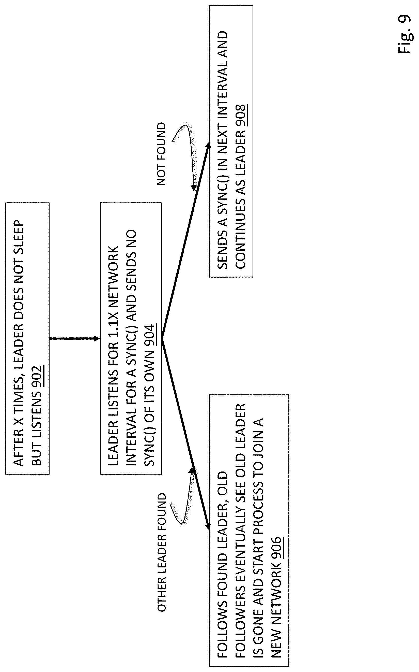
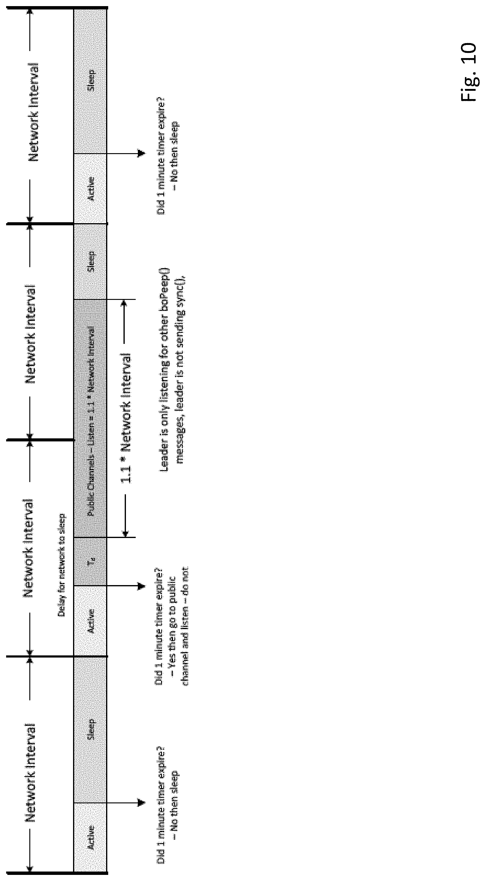
[0030] In an aspect, a network for connecting a plurality of network nodes with features as described herein includes a leader node; and a plurality of follower nodes, wherein the leader node transmits a sync message to the plurality of follower nodes indicating a beginning of a network interval, wherein the leader node and the plurality of follower nodes transmit information during a transmission period and do not transmit information during a sleep period of the network interval, and wherein during a predetermined time of the transmission period of the network interval each of the follower nodes that received the sync message transmit a message advertising one or more properties of the leader node. The one or more properties of the leader node includes at least one of a channel hopping sequence and a total number of the network nodes on the network. When any of the plurality of follower nodes fails to receive a receive a sync message from the leader node, the follower node refrains from transmitting a message advertising a property of the leader node during the network interval. The message advertising a property of the leader node is broadcast on a predetermined subset of channels. A new follower node attempting to join the network listens on the predetermined subset of channels to receive the message advertising at least one property of the leader node to learn the at least one property of the leader node to facilitate the new follower node to join the network. At least one property comprises the total number of network nodes already on the network and the new follower node will refrain from attempting to join the network when the total number of network nodes exceeds a predetermined value. After a predetermined interval, the leader node refrains from sending the sync message and entering the sleep period for at least one network interval and listens for messages advertising at least one property of a different leader node. The leader node is a gas sensor. If the leader node receives a message advertising at least one property of the different leader node, the leader node starts a process to cease performing as the leader node and begin performing as a follower node of the different leader node. If the leader node does not receive a message advertising at least one property of another leader node, the leader node continues to perform as the leader node. The leader node and plurality of follower nodes use less power in the sleep period than the transmission period, the plurality of follower nodes each comprising a timer, the timer adapted to time the transmission period and sleep period of a plurality of future network intervals in an absence of continued receipt of the sync message from the leader node during the plurality of future network intervals. When the follower nodes transmit the message advertising the one or more properties of the leader node, the message is transmitted with a single hop such that a node receiving the message does not retransmit the message.
[0031] In an aspect, a method of operating a wireless mesh network with features as described herein includes the steps of: providing a plurality of nodes wherein each node is operable to perform as a leader node or a follower node, wherein one node performs to identify itself as the leader node and one or more other nodes operate as follower nodes; wherein the leader node transmits a sync message to follower nodes indicating a beginning of a network interval, wherein the leader node and the follower nodes transmit information during a transmission period and do not transmit information during a sleep period of the network interval, and wherein during a predetermined time of the transmission period of the network interval follower nodes that received the sync message transmit a message advertising one or more properties of the leader node. The one or more properties of the leader node includes at least one of a channel hopping sequence and a total number of the network nodes on the network. When any of the plurality of follower nodes fails to receive a receive a sync message from the leader node, the follower node refrains from transmitting a message advertising a property of the leader node during the network interval. The message advertising a property of the leader node is broadcast on a predetermined subset of channels. A new follower node attempting to join the network listens on the predetermined subset of channels to receive the message advertising at least one property of the leader node to learn the at least one property of the leader node to facilitate the new follower node to join the network. The at least one property comprises the total number of network nodes already on the network and the new follower node will refrain from attempting to join the network when the total number of network nodes exceeds a predetermined value. After a predetermined interval, the leader node refrains from sending the sync message and entering the sleep period for at least one network interval and listens for messages advertising at least one property of a different leader node. The leader node is a gas sensor. If the leader node receives a message advertising at least one property of the different leader node, the leader node starts a process to cease performing as the leader node and begin performing as a follower node of the different leader node. If the leader node does not receive a message advertising at least one property of another leader node, the leader node continues to perform as the leader node. The leader node and plurality of follower nodes use less power in the sleep period than the transmission period, the plurality of follower nodes each comprising a timer, the timer adapted to time the transmission period and sleep period of a plurality of future network intervals in an absence of continued receipt of the sync message from the leader node during the plurality of future network intervals. When the follower nodes transmit the message advertising the one or more properties of the leader node, the message is transmitted with a single hop such that a node receiving the message does not retransmit the message.
[0032] In an aspect, a network with features as described herein for connecting a plurality of network nodes comprising: a first leader node; and a plurality of follower nodes, wherein the first leader node transmits a sync message to the plurality of follower nodes indicating a beginning of a network interval, wherein the plurality of follower nodes transmit information during a transmission period and do not transmit information during a sleep period of the network interval, and wherein during a predetermined time of the transmission period of the network interval each of the follower nodes that received the sync message transmit a message advertising one or more properties of the first leader node; and wherein transmission period, the first leader nodes listens for information advertising one or more properties of a second leader node. The message advertising a property of the second leader node is transmitted on a predetermined channel. The first leader node listens on the predetermined channel. The message advertising a property of the second leader node is also transmitted on a second predetermined channel. The first leader node also listens on the second predetermined channel. The first leader node listens for a period of time greater than the length of the network interval. When the first leader node receives for information advertising one or more properties of a second leader node, the first leader node ceases performing as a leader node and is adapted to begin a sequence to join the second leader node as a follower node. The plurality of follower nodes are adapted to detect an absence of the first leader node and begin a sequence to join a new leader node. The leader node and plurality of follower nodes use less power in the sleep period than the transmission period, the plurality of follower nodes each comprising a timer, the timer adapted to time the transmission period and sleep period of a plurality of future network intervals in an absence of continued receipt of the sync message from the leader node during the plurality of future network intervals. The network nodes are environmental sensing devices. The information is assigned by reading an NFC tag. The information relates to a concentration of gas. The information relates to an environmental attribute. The one or more properties is assigned by reading an NFC tag.
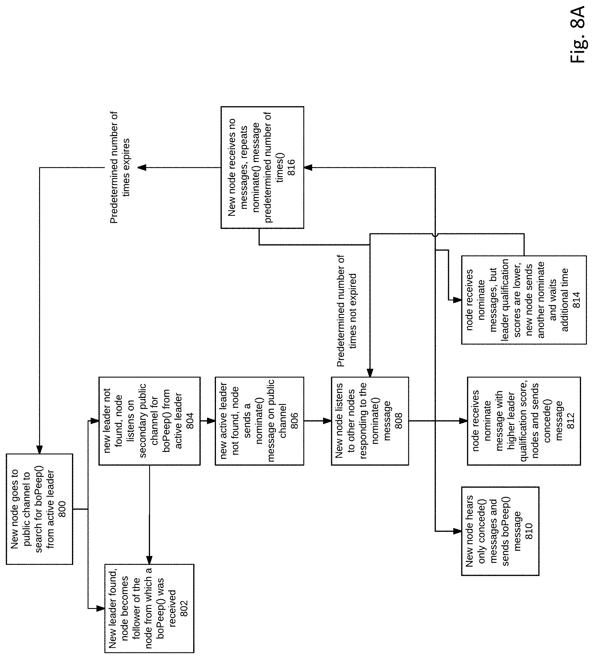
[0033] In an aspect, a network with features as described herein for connecting a plurality of network nodes comprising: a leader node; and a plurality of follower nodes, wherein the leader node transmits a sync message to the plurality of follower nodes indicating a beginning of a network interval, wherein the plurality follower nodes each comprise a counter for tracking the receipt of sync messages received from the leader node and the counter is incremented when a sync message is received and decremented when a sync message is not received, wherein any of the plurality of follower nodes will begin a process of electing new leader node when the counter decreases to a predetermined value. The leader node and the plurality of follower nodes transmit information during a transmission period and do not transmit information during a sleep period of the network interval. The follower node whose counter has decremented to the predetermined value transmits a first nominate message to begin the process of electing a new leader node. The first nominate message is transmitted on a predetermined channel. The first nominate message is also transmitted on a second predetermined channel. The first nominate message includes data related to the suitability of the follower node sending the first nominate message to act as a leader node. The data is calculated from a strength and reliability of signals received from other network nodes on the network. The data is calculated by utilizing at least one of an instrument type of the follower node, a battery state of charge, and past signal quality. The first nominate message and data are received by other network nodes and the data compared by the receiving network nodes to data related to a suitability of the receiving network nodes to act as a leader node, wherein the receiving network nodes reply with either a reply nominate message with data indicating a higher suitability to act as a leader node or a concede message if the receiving network node does not have a higher suitability to act as a leader node. When the follower node sending the first nominate message receives only concede messages, that follower node assumes the role of leader node and advertises at least one property of itself as a leader node for other network nodes to become follower nodes. When the follower node sending the first nominate message receives a nominate message with data indicating a higher suitability to act as a leader node, that follower node sends a concede message. The concede messages are transmitted on the predetermined channel. The concede messages are also transmitted on the second predetermined channel.
[0034] In an aspect, a network with features as described herein for connecting a plurality of network nodes comprising: a leader node; and a plurality of follower nodes, wherein the leader node transmits sync message to the plurality of follower nodes indicating a beginning of successive network intervals, wherein upon nonreceipt of a predetermined number of sync messages by a follower node that follower node initiates a process of electing a new leader node by a sending a first nominate message that includes data related to the suitability of the follower node to act as a leader node. The plurality of follower nodes each comprise a counter for tracking the receipt of sync messages received from the leader node and the counter is incremented when a sync message is received and decremented when a sync message is not received, wherein any of the plurality of follower nodes will begin a process of electing new leader node when the counter decreases to the predetermined value. The first nominate message is transmitted on a predetermined channel. The first nominate message is also transmitted on a second predetermined channel. The data is calculated from a strength and reliability of signals received from other network nodes on the network. The data is calculated by utilizing at least one of an instrument type of the follower node, a battery state of charge, and past signal quality. The first nominate message and data are received by other network nodes and the data compared by the receiving network nodes to data related to a suitability of the receiving network nodes to act as a leader node, wherein the receiving network nodes reply with either a reply nominate message with data indicating a higher suitability to act as a leader node or a concede message if the receiving network node does not have a higher suitability to act as a leader node. When the follower node sending the first nominate message receives only concede messages, that follower node assumes the role of leader node and advertises at least one property of itself as a leader node for other network nodes to become follower nodes. When the follower node sending the first nominate message receives a nominate message with data indicating a higher suitability to act as a leader node, that follower node sends a concede message. The concede messages are transmitted on the predetermined channel. The concede messages are also transmitted on the second predetermined channel. The network nodes are environmental sensing devices. The information is assigned to the node by reading an NFC tag. The information relates to a concentration of gas. The information relates to an environmental attribute. The network nodes are environmental sensing devices.
[0035] In an aspect, a method of providing information about a leader node to a plurality of follower nodes in a wireless mesh communication network with features as described herein comprising: designating the leader node; designating the plurality of follower nodes; designating one or more predetermined frequency ranges as a public channel; from the leader node and during a plurality of network intervals having a predetermined length of time, transmitting a sync message at a beginning of each network interval to the plurality of follower nodes; and during each network interval in which a sync message is received by any one of the follower nodes, transmitting from any of the plurality of follower node receiving a sync message, upon the least one public channel, a message advertising at least one property of the leader node after receipt of the sync message. The leader node also sends a message advertising at least one property of the leader node in any network interval in which a sync message is transmitted. The method may further include providing a new follower node not yet configured to receive the sync message; with the new follower node, listening to the public channel until the at least one property of the leader node is broadcast; and from the at least one property, causing the new follower node to configure itself to communicate with the leader node on the next network cycle to join the network. The at least one property of the leader node comprises at least one of frequency hop parameters and the total number of leader and follower nodes on the network. The at least one property of the leader node comprises frequency hop parameters comprising a multiplier, an intercept and a seed for linear congruent generator. The frequency hop parameters further comprise channel mask parameters defining predetermined channels as either one of used and unused. The frequency hop parameters further comprise a length of time for the network interval. The at least one property of the leader node comprises the total number of leader and follower nodes on the network and wherein the new follower node will not attempt to join the network if the total exceeds a predetermined value. The leader node and follower nodes are environmental sensing devices.
[0036] In an aspect, a method of joining a new device to a mesh wireless network with features as described herein comprising: providing a mesh wireless network comprising a leader node and a plurality of follower nodes; designating at least one predetermined frequency range as a public channel; transmitting on the public channel information advertising at least one property of the leader node; with a new device to the mesh wireless network, listening on the public channel for the information transmitted advertising at least one property of the leader node; configuring the new device to follow the leader device using the at least one advertised property describing the leader node; with the new device to the mesh wireless network, receiving a sync message transmitted from the leader node; and requesting the leader node to join the mesh wireless network. The step of transmitting on the public channel information advertising at least one property of the leader node is performed by at least one of the follower nodes in response to receipt of a sync message. The step of transmitting on the public channel information advertising at least one property of the leader node is performed by the leader node after transmission of a sync message. The at least one property of the leader node comprises at least one of frequency hop parameters and the total number of leader and follower nodes on the network. The at least one property of the leader node comprises frequency hop parameters comprising a multiplier, an intercept and a seed for linear congruent generator. The frequency hop parameters further comprise channel mask parameters defining predetermined channels as either one of used and unused. The frequency hop parameters further comprise a length of time for the network interval. The at least one property of the leader node comprises the total number of leader and follower nodes on the network and wherein the new follower node will not attempt to join the network if the total exceeds a predetermined value.
[0037] In an aspect, a method of joining a follower node to a leader node in a wireless mesh communication network with features as described herein comprising: designating the leader node; designating the plurality of follower nodes; designating one or more predetermined frequency ranges as a public channel; from the leader node and during a plurality of network intervals having a predetermined length of time, transmitting a sync message at a beginning of each network interval to the plurality of follower nodes; during each network interval in which a sync message is received by any one of the follower nodes, transmitting from any of the plurality of follower nodes receiving a sync message, upon the least one public channel, a message advertising at least one property of the leader node after receipt of the sync message; providing a new follower node not yet configured to receive the sync message; with the new follower node, listening to the public channel until the at least one property of the leader node is broadcast and received by the new follower node; and from the at least one property, causing the new follower node to configure itself to communicate with the leader node on the next network cycle to join the network. The method further includes providing a new follower node not yet configured to receive the sync message; with the new follower node, listening to the public channel until the at least one property of the leader node is broadcast; and from the at least one property, causing the new follower node to configure itself to communicate with the leader node on the next network cycle to join the network. The at least one property of the leader node comprises at least one of frequency hop parameters and the total number of leader and follower nodes on the network. The at least one property of the leader node comprises frequency hop parameters comprising a multiplier, an intercept and a seed for linear congruent generator. The frequency hop parameters further comprise channel mask parameters defining predetermined channels as either one of used and unused. The frequency hop parameters further include a length of time for the network interval. The at least one property of the leader node comprises the total number of leader and follower nodes on the network and wherein the new follower node will not attempt to join the network if the total exceeds a predetermined value. The leader node is an environmental sensing device. The devices are environmental sensing devices. The leader node and follower nodes are environmental sensing devices.
[0038] In an aspect, a network with features as described herein for connecting a plurality of network nodes comprising: a leader node; and a plurality of follower nodes, wherein the leader node transmits a sync message to the plurality of follower nodes indicating a beginning of a network interval, wherein the sync message contains data indicating the number of network nodes in the network, wherein the leader node and the plurality of follower nodes transmit information during a transmission period of the network interval and do not transmit information during a sleep period of the network interval, wherein the network interval is of a fixed length of time, the transmission period is of a variable length of time based upon the number of network nodes in the network, and the sleep period comprises remaining time of the network interval after the transmission period. The transmit time is divided between a first transmit time for transmitting high priority data and a second transmit time for lower priority data. The first transmit time and the second transmit time are equal length periods of time. The leader node and plurality of follower nodes use less power in the sleep period than the transmission period, the plurality of follower nodes each comprising a timer, the timer adapted to time the transmission period and sleep period of a plurality of future network intervals in an absence of continued receipt of the sync message from the leader node during the plurality of future network intervals. When any of the plurality of follower nodes receive a sync message, the follower node transmits a message advertising one or more properties of the leader node during a predetermined period of the network interval. The one or more properties of the leader node includes at least one of a channel hopping sequence and a total number of the network nodes on the network. When the timer is further adapted to time an expected receipt of future sync messages of future network intervals and when an actual receipt of the future sync message deviates from an expected receipt of the future sync message by a predetermined amount of time for a predetermined number of network intervals, the follower node adjusts the timer to more closely correspond with the actual receipt of the future sync message. The network nodes are environmental sensing devices. The information is assigned to the node by reading an NFC tag. The information relates to a concentration of gas. The information relates to an environmental attribute.
[0039] In an aspect, a network with features as described herein for connecting a plurality of network nodes comprising: a leader node; and a plurality of follower nodes, wherein the leader node transmits a successive plurality of sync messages to the plurality of follower nodes indicating a beginning of successive network intervals, wherein the leader node and the plurality of follower nodes transmit information during a transmission period of each network interval and wherein the leader node changes a channel of the sync message in subsequent network intervals according to a channel change schedule and wherein the plurality of follower nodes change a channel to receive the sync messages of successive network intervals according to the same channel change schedule, and leader node does not change a channel of transmission during the transmission period of the network interval. The channel change schedule changes the channel for each successive network interval. The channel change schedule changes the channel after a plurality of network intervals. The channel change schedule is changed according to a linear congruential generator. When any of the plurality of follower nodes receive a sync message, the follower node transmits a message advertising one or more properties of the channel change schedule. The channel change schedule is changed according to a linear congruential generator. The one or more properties of the channel change schedule comprises a seed, a multiplier and an intercept for the linear congruential generator. The channel change schedule further indicates channels that are unavailable to broadcast the sync message. The channel change schedule further indicates channels that are available to broadcast the sync message. The network nodes are environmental sensing devices. The information is assigned to the node by reading an NFC tag. The information relates to a concentration of gas. The information relates to an environmental attribute.
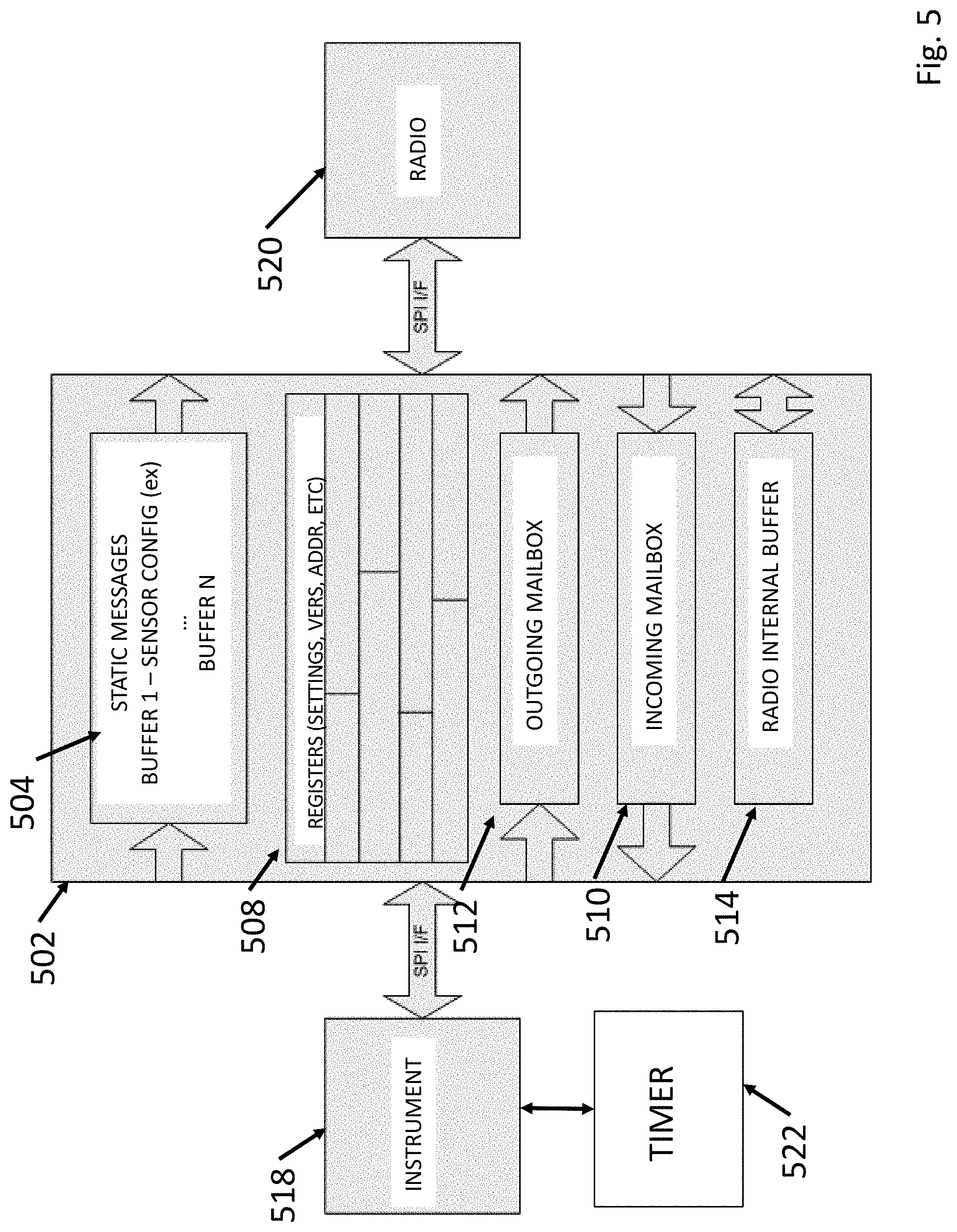
[0040] In an aspect, a static memory device comprising: an instrument comprising at least one of an environmental sensing device, a hazard detection device, and an industrial safety device, the instrument operating in a first sleep cycle in which the instrument is generating data related to the instrument type; a wireless radio for sending and receiving information on a wireless mesh network with features as described herein, the radio operating a second sleep cycle different from the first sleep cycle in at least one of period and phase; and a shared memory operatively connected to the instrument and the radio, the shared memory comprising static message memory comprising static messages related to the instrument; an outgoing memory portion that receives outgoing information from the instrument and transmits the outgoing information to the radio for transmission on the wireless mesh network, an incoming memory portion that receives incoming information from the radio and transmits the incoming information to instrument, the shared memory further comprising request and grant lines for the radio and for the instrument to allow the radio and the instrument to request and grant data to the incoming memory or the outgoing memory, wherein the shared memory is adapted to not allow the both the radio and the instrument to raise the grant lines and grant data to either the incoming or the outgoing memory simultaneously. The device further includes a radio internal buffer for providing additional memory space to the radio. The first and second sleep cycles differ in both period and phase. The shared memory further comprises an urgent line that provides an indicator to the instrument or the radio that the information in outgoing or incoming memory portion should be accessed immediately. The information is assigned to the node by reading an NFC tag. The information relates to a concentration of gas. The information relates to an environmental attribute.
[0041] In an aspect, a network for connecting a plurality of network nodes comprising: a static memory device comprising: an instrument comprising at least one of an environmental sensing device, a hazard detection device, and an industrial safety device, the instrument operating in a first sleep cycle in which the instrument is generating data related to the instrument type; a wireless radio for sending and receiving information on a wireless mesh network with features as described herein, the radio operating a second sleep cycle different from the first sleep cycle in at least one of period and phase; and a shared memory operatively connected to the instrument and the radio, the shared memory comprising static message memory comprising static messages related to the instrument; an outgoing memory portion that receives outgoing information from the instrument and transmits the outgoing information to the radio for transmission on the wireless mesh network, an incoming memory portion that receives incoming information from the radio and transmits the incoming information to instrument, the shared memory further comprising request and grant lines for the radio and for the instrument to allow the radio and the instrument to request and grant data to the incoming memory or the outgoing memory, wherein the shared memory is adapted to not allow the both the radio and the instrument to raise the grant lines and grant data to either the incoming or the outgoing memory simultaneously; and a wireless mesh network communicating with the radio comprising: a leader node; and a plurality of follower nodes, wherein the leader node transmits a sync message to the plurality of follower nodes indicating a beginning of a network interval, wherein the leader node and the plurality of follower nodes transmit information during a transmission period of the network interval and do not transmit information during a sleep period of the network interval, the leader node and plurality of follower nodes using less power in the sleep period than the transmission period, the plurality of follower nodes each comprising a timer, the timer adapted to time the transmission period and sleep period of a plurality of future network intervals in an absence of continued receipt of the sync message from the leader node during the plurality of future network intervals. The network further includes a radio internal buffer for providing additional memory space to the radio. The first and second sleep cycles differ in both period and phase. The shared memory further comprises an urgent line that provides an indicator to the instrument or the radio that the information in outgoing or incoming memory portion should be accessed immediately. The information is assigned to the node by reading an NFC tag. The information relates to a concentration of gas. The information relates to an environmental.
[0042] In an aspect, a mesh network device for connecting to, sending and receiving information on a mesh wireless network with features as described herein comprising: an instrument comprising at least one of an environmental sensing device, a hazard detection device, and an industrial safety device, a radio for transmitting and receiving information on the mesh wireless network; and a display for presenting a signal quality indicator of a connection of the radio to other nodes of the mesh wireless network, the signal quality indicator derived from a combination of the received signal strength (RSS) and packet receive ratio (PRR) of all the instruments in the mesh wireless network. The instrument multiplies an RSS of a most recent message received from each node in the mesh network by the PRR, which is the ratio of packets received from each device in the mesh wireless network to a number of expected packets from each respective device in the mesh wireless network. The RSS represents a most recent network hop taken by a packet. The PRR is a counter that begins at a predetermined number and is incremented and decremented when expected packets are received or not received, respectively. The increment and decrement values are 3 and 2, respectively. The signal quality indicator is based on the product of RSS*PRR for each node, summed and divided by a number of nodes in the network. An alarm sounds when the signal quality indicator drops below a predetermined level. The information is assigned to the node by reading an NFC tag. The information relates to a concentration of gas. The information relates to an environmental attribute.
[0043] In an aspect, a network with features as described herein for connecting a plurality of network nodes comprising: a leader node; and a plurality of follower nodes, wherein the leader node transmits a sync message to the plurality of follower nodes indicating a beginning of a network interval, wherein the sync message contains data indicating the number of network nodes in the network, wherein the leader node and the plurality of follower nodes transmit information during a transmission period of the network interval and do not transmit information during a sleep period of the network interval, wherein each of the plurality of the follower nodes randomly select an interval during the transmission period to transmit data and without respect to a time selected by any of the other follower nodes. The time randomly selected is with reference to beginning of the transmission period. The network interval is of a fixed length of time, the transmission period is of a variable length of time based upon the number of network nodes in the network, and the sleep period comprises remaining time of the network interval after the transmission period. The transmission period is divided between a first transmit time for transmitting high priority data and a second transmit time for lower priority data and wherein the time randomly selected to transmit data is with reference to the beginning of the first transmit time and the second transmit time. The first transmit time and the second transmit time are equal length periods of time. The leader node and plurality of follower nodes use less power in the sleep period than the transmission period, the plurality of follower nodes each comprising a timer, the timer adapted to time the transmission period and sleep period of a plurality of future network intervals in an absence of continued receipt of the sync message from the leader node during the plurality of future network intervals. When any of the plurality of follower nodes receive a sync message, the follower node transmits a message advertising one or more properties of the leader node during a predetermined period of the network interval. The one or more properties of the leader node includes at least one of a channel hopping sequence and a total number of the network nodes on the network. When the timer is further adapted to time an expected receipt of future sync messages of future network intervals and when an actual receipt of the future sync message deviates from an expected receipt of the future sync message by a predetermined amount of time for a predetermined number of network intervals, the follower node adjusts the timer to more closely correspond with the actual receipt of the future sync message. The network nodes are environmental sensing devices. The information is assigned to the node by reading an NFC tag. The information relates to a concentration of gas. The information relates to an environmental attribute.
[0044] In an aspect, a network with features as described herein for connecting a plurality of network nodes comprising: a leader node; and a plurality of follower nodes, wherein the leader node transmits a sync message to the plurality of follower nodes indicating a beginning of a network interval, wherein the sync message contains data indicating the number of network nodes in the network, wherein the leader node and the plurality of follower nodes transmit information during a transmission period of the network interval and do not transmit information during a sleep period of the network interval, wherein the transmission period is divided between a first transmit time for transmitting high priority data and a second transmit time for transmitting lower priority data. Each of the plurality of the follower nodes randomly select an interval during the transmission period to transmit data and without respect to a time selected by any of the other follower nodes and wherein the time randomly selected to transmit data is with reference to the beginning of the first transmit time and the second transmit time. The network interval is of a fixed length of time, the transmission period is of a variable length of time based upon the number of network nodes in the network, and the sleep period comprises remaining time of the network interval after the transmission period. The first transmit time and the second transmit time are equal length periods of time. The leader node and plurality of follower nodes use less power in the sleep period than the transmission period, the plurality of follower nodes each comprising a timer, the timer adapted to time the transmission period and sleep period of a plurality of future network intervals in an absence of continued receipt of the sync message from the leader node during the plurality of future network intervals. When any of the plurality of follower nodes receive a sync message, the follower node transmits a message advertising one or more properties of the leader node during a predetermined period of the network interval. The one or more properties of the leader node includes at least one of a channel hopping sequence and a total number of the network nodes on the network. When the timer is further adapted to time an expected receipt of future sync messages of future network intervals and when an actual receipt of the future sync message deviates from an expected receipt of the future sync message by a predetermined amount of time for a predetermined number of network intervals, the follower node adjusts the timer to more closely correspond with the actual receipt of the future sync message. The network nodes are environmental sensing devices. The information is assigned to the node by reading an NFC tag. The information relates to a concentration of gas. The information relates to an environmental attribute.
[0045] These and other systems, methods, objects, features, and advantages of the present disclosure will be apparent to those skilled in the art from the following detailed description of the preferred embodiment and the drawings.
[0046] All documents mentioned herein are hereby incorporated in their entirety by reference. References to items in the singular should be understood to include items in the plural, and vice versa, unless explicitly stated otherwise or clear from the text. Grammatical conjunctions are intended to express any and all disjunctive and conjunctive combinations of conjoined clauses, sentences, words, and the like, unless otherwise stated or clear from the context.
BRIEF DESCRIPTION OF THE FIGURES
[0047] The disclosure and the following detailed description of certain embodiments thereof may be understood by reference to the following figures:
[0048] FIG. 1 depicts an overview of the worker safety system.
[0049] FIG. 2 depicts a challenging environment for networking.
[0050] FIG. 3 depicts a system for propagating an alarm in a mesh network.
[0051] FIG. 4 depicts frequency channel overlap.
[0052] FIG. 5 depicts a shared memory interface.
[0053] FIG. 6A depicts a list of instruments on a display.
[0054] FIG. 6B depicts a shadow gas display.
[0055] FIG. 7 depicts a script process for the wireless network.
[0056] FIG. 8 depicts a synchronization scheme and FIG. 8A depicts a method for choosing a leader from members of a network.
[0057] FIG. 9 depicts a leader election process.
[0058] FIG. 10 depicts a sleep cycle process.
[0059] FIG. 11 depicts the wireless network mesh architecture.
[0060] FIG. 12 depicts how the hardware enabling wireless network-compatibility can be extended to a platform using gateways to the Internet.
[0061] FIG. 13 depicts the wireless network fitting in a 7-layer OSI Model.
[0062] FIG. 14 depicts a method of the disclosure.
[0063] FIG. 15 depicts a block diagram of an embodiment of the disclosure.
[0064] FIG. 16 depicts a method of providing safety alerts.
DETAILED DESCRIPTION
[0065] Referring to FIG. 1, in order to provide various services and monitoring in a real-time or near-real time fashion with respect to portable environmental sensing devices, hazard detection devices, and other safety instruments and devices, instruments and devices is such a system need reliable methods communicate with each other and/or with a remote location, all while in a challenging environment. This disclosure describes various aspects of a worker safety system, general components of which are shown in FIG. 1. The disclosure describes various communications strategies and technologies to enable various applications and services related to worker safety. In addition to showing the general components of such a system, FIG. 1 and the accompanying description provide an overview of the communication approaches and strategies, certain useful accessories, and various applications enabled by the worker safety system.
[0066] FIG. 1 illustrates certain portable environmental sensing devices 108 and area monitors 110, but it should be noted that other safety devices may be used with the system such as, multi-gas detection instruments, a gas detection instruments, a portable electrochemical gas sensing apparatuses, respirators, a harness, lighting devices, fall arrest devices, thermal detectors, flame detectors, or a chemical, biological, radiological, nuclear, and explosives (CBRNE) detector. In embodiments, environmental sensing device may be as described in "VENTIS PRO" U.S. Pat. Nos. 9,000,910, 9,575,043, 6,338,266, 6,435,003, 6,888,467, and 6,742,382, which are incorporated by reference herein in their entirety. In embodiments, area monitors such as described herein as well as in U.S. Patent Application Publication No. 2016/0209386, entitled MODULAR GAS MONITORING SYSTEM and filed on Jan. 15, 2016, the disclosure of which is incorporated herein by reference in its entirety. Throughout this disclosure, the terms environmental sensing devices (or instruments) 108, area monitors 110, and it should be understood that any of methods, systems, applications, interfaces, and the like described herein may be used by any of the environmental sensing devices (or instruments) 108, and area monitors 110. In addition, the disclosure may refer to environmental sensing devices and area monitors collectively as "instruments". In embodiments, the environmental sensing devices 108 and area monitors 110 may communicate with one another using a mobile ad hoc wireless network (MANET) 104. As used herein, the term MANET is a continuously self-configuring, infrastructure-less network of mobile devices connected wirelessly. One such MANET that may be implemented is a mesh network. As used herein a mesh network is a network topology in which each node relays data for the network and all mesh nodes cooperate in the distribution of data in the network. Embodiments of the mesh network between environmental sensing devices 108 and area monitors 110 will be described further herein. In embodiments, the mesh network can enable communication between components of the system without the need of other conventional communications technology for wireless communication, such as WiFi, satellite, or cellular technologies. Because the mesh wireless network overcomes the challenge of operating a computer network where devices communication solely with a centralized device, such as a hub, switch or router, the network better operates in challenging environments where obstructions or distance prevent wireless communication from a device to a hub. By utilizing the mesh network, devices can communicate with one another to transmit messages from devices to other devices to communicate with one another or to pass information among devices or to eventually transmit the message to a device on the perimeter of the network for forwarding to another network, such as a device in the cloud. Industrial environments also typically represent challenging environments because sensors may be constantly moving or regularly changing location, the environment can be large or remote from public wireless infrastructure, large obstruction such as metal tanks may block signals, and the environment may be underground. This disclosure may also include devices, nodes, and the like communicating on a peer-to-peer network (P2P), which may be part of a mesh network. It should be understood that the embodiments described herein may operate on a mesh network, P2P network, or similar type of network. FIG. 1 also depicts various approaches to ultimately communicate data from the instruments to the cloud or remote server, such as via an API 114, smart device 118 or other mobile gateway 131, a gateway 112, and a dock 122.
[0067] In embodiments, the mesh network 104 of this disclosure delivers "ready to use" wireless functionality to instrument platforms. When equipped with hardware to be compatible with the mesh network 104 and embedded firmware, instruments are able to communicate wirelessly with one another. Mesh wireless networking provides instrument features such as peer alarms, or "shadowing" readings from one instrument on another instrument's screen--all within challenging environments typical to industrial safety. The mesh networking feature set is available for area monitors and portable instruments and enables interoperability, allowing a mixed network of portable and area monitor instruments to share readings and alarms.
[0068] Instruments 108 also communicate, via the mesh network with other mesh network-enabled infrastructure devices that further enable live monitoring, automated messaging, and location awareness, such other mesh network-enabled infrastructure devices including network gateway device (also referred to herein as "gateway") 112 and docks 122. For example, a network gateway device 112 may be placed in location in proximity to instruments, devices, computers, vehicles, equipment, and the like to enable communication with a network infrastructure. The instruments may communicate with the network gateway device 112 through the mesh network 104, and in embodiments, the data may be ultimately communicated, to a cloud server, via networking technology, such as WiFi, cellular, satellite, and the like, for downstream uses, for example by a remote server as described herein. There may be two-way communication through the gateway 112 such that remote servers or applications running in the cloud may be used to control, configure or otherwise communicate with the instruments 108, 110 through the gateway 112.
[0069] In embodiments, the dock 122, or docking station, may be used with the instrument to provide predictive diagnostic information, as described in U.S. Pat. No. 6,442,639, entitled Docking Station for Environmental Monitoring Instruments, which is incorporated by reference in its entirety herein. The docking station or gateway 112 (or API 114/Smart Device 118/mobile gateway 131 as described herein) may be connected, typically via the Internet, to a remote server 130, and exposure data, calibration data and diagnostic data are communicated from the instrument to the docking station and from the docking station to the remote server 130. Mathematical analysis of the collected data from all available sources is performed by the remote server 130 to, among other things, generate predictive warnings to alert the users of potential instrument faults, thus allowing preemptive maintenance, incident management, and the like. The analysis methods include principle component analysis and other statistical methods, fuzzy logic and neural networks. In embodiments, the worker safety system can take data from components of the system, store such data, generate reports to be sorted based on the data and communicate the data to a user. Such data communicated to a user can include, for example, events, need for calibration/bump testing, maintenance record, alert that settings are incorrect or sub-optimal, and error codes. The remote server 130 may also generate alerts to send to users, can change settings remotely, can alert a user if another user has an alarm and provide information on where to respond, and other end use applications as described herein.
[0070] The mesh network may be tailored to the unique needs of worker-to-worker communication. In an embodiment, the wireless network may be applied to the challenge of hazardous gas detection--relaying alarms and readings among a group of gas detection instruments in the challenging environments described herein. Referring to FIG. 2, a particular challenging environment is shown. Instruments 108 and 110 communicate with a beacon 102, a tag 132, a wearable 134 and to a gateway 112 through an external cellular, satellite, or WiFi network 136 to the cloud 138. A large metal tank 140 is present in the environment though which signals will not pass. FIG. 2 illustrates that instruments 108 and 110 either communicate with nearby instruments 108 and/or 110 and not with remote instruments or instruments blocked by obstructions, such as tank 200. Instruments 108 and 110 interoperate to create paths for data between instruments 108 and 110 which are not directly connected.
[0071] True mesh communications allowing sensors to communicate directly with one another is novel in portable gas detection. Daisy-chain alarms, such as perimeter or fence line, for area monitoring exist, but current wireless implementations for portable devices 108 only relay information to a central display or "controller", such as a laptop computer or a dedicated display device.
[0072] This disclosure describes the features of the wireless network, and how these features work in concert to address the challenges of worker-to-worker communications. These challenges include ease of use, difficult environment, dynamic network topologies, and power consumption.
[0073] The mesh wireless network 104 may relay an alarm notification from one instrument to another instrument. "Peers" could be, for example, two portable instruments worn by two members of a crew, three area monitors surrounding a work zone, or some combination thereof. Peers are equals in the network and information may be exchanged in both directions.
[0074] Points in a network are called nodes. Nodes in the mesh wireless network 104 may include instruments 108, 110, devices 118, beacons 102 (which are described further herein), gateways 131, 112, docks 122, and the like. Most wireless networks have a coordinator node, a single entity in the network to coordinate the activities of others. In star network topologies such as WiFi, the coordinator node is the access point. In Bluetooth, the coordinator node is the master (smartphone or PC). In other mesh protocols like Zigbee and WirelessHART, a dedicated coordinator node is used. ZigBee is a registered trademark of Philips Electronics North American Corporation. WirelessHART is a registered trademark of Hart Communication Foundation. In all of these cases, the coordinator role is necessary for the network to operate and is a dedicated device for performing the coordinator function. The coordinator manages routing tables, sets Time Division Multiple Access (TDMA) slots, coordinates frequency hopping, etc. The coordinator may be line-powered for reliability and availability for communication. For example, in WirelessHART, the role of the coordinator is vital, a backup coordinator is held in reserve, just in case the primary coordinator fails.
[0075] A coordinator node is not required with the mesh wireless network 104 of the present invention, as it is a truly ad-hoc network. Any collection of two or more instruments may form a network, without the need for any infrastructure. The mesh network 104 can tolerate the loss of any member, at any time, without warning because each device communicates with all other devices within range and maintains a database of devices from whom communications have been received. When messages from a device have not been received within a predetermined period of time, the device is removed from the database.
[0076] For security, every node has a default private encryption key which may be changed. By changing the encryption key, a network can be kept secure but also can be altered to keep mesh networks intended to operate separately in the same space from communicating with one another, such as keeping the network of different contractors in an industrial environment from contacting one another. The network is blind to nodes operating on a different encryption key. Also for security, dynamic frequency hopping, as described below, is implemented so that the channel on which the network will be communicating is pseudo-random and constantly changes. Finally, security may be implemented by bringing a node into contact or near-contact with a near field communication device ("NFC") to identify and authorize that node on the network, as described below.
[0077] High bandwidth, low latency MANETs, like those used on the battlefield, are extremely sophisticated. They involve multi-radio units and significant communications processing hardware, but wireless environmental sensing such as gas detection may not require this level of performance. The mesh network 104 excels at sharing a small amount of information, with a plurality of other instruments, with relatively low (such as a few seconds) delay without the complexity of existing high-bandwidth, low latency MANETs. One feature eliminating the complexity of other MANETs is that the mesh network 104 assumes messages reach their destination
[0078] In embodiments, the mesh network 104 emphasizes energy efficiency using power-efficient broadcasts of information. The network 104 operates on a constant network interval, for example 1 second. Within the network interval is a period of broadcasting and a period of sleep cycling. Moreover, the length of the period of broadcasting is altered in the mesh network 104 based upon the number of devices currently joined to the network, such that a network with few devices can be even more power efficient by increasing the period of sleep cycling within each network interval, as further described below.
[0079] In embodiments, the mesh network 104 may not be a long-range link. The mesh network 104 may typically operate at distances of 100-200 m between individual nodes, and is not intended for remote monitoring of a distant site. The mesh network 104 feature set is meant to communicate between, and alert workers within, the same group and working in the same vicinity. It provides acceptable range and coverage by leveraging the mesh topology.
[0080] The mesh network 104 shares information and alarms with other instruments without a dedicated coordinator node, or any fixed nodes for that matter.
[0081] In embodiments, the mesh network 104 provides a setting-free, self-forming, self-healing, resilient wireless network without a dedicated coordinator node. As described below, there are no user settings required, no channel selection, and no PAN id to enter. In one embodiment, with the intuitive action of touching two instruments together, a network may be formed. Touching another instrument to an existing member of a network joins the new instrument into the network if the instrument is not already in a network itself. Touching the instruments may be a tap, double tap, bump, both being shaken together, a touch of the tops of the instruments, a touch of the bottoms of the instruments, and the like. In embodiments, if when the instruments are tapped it is determined that they are each already members of a different network, each instrument may be prompted to leave their network, and if one leaves, upon re-tapping, the network joining may be successful. In a distributed fashion, the network is maintained and adapts as member instruments come and go and move about the challenging RF environment typical of industrial settings.
[0082] The wireless network's adaptability and resilience is a result of an emphasis on wireless diversity. This diversity takes three forms: space diversity, frequency diversity, and time diversity. Space diversity involves transmitting a wireless signal over several different propagation paths, with the understanding that different paths experience radically different RF impediments. Space diversity is the reason most WiFi access points have more than one antenna--even separating two antennas by a few inches significantly reduces "dead spots" in coverage caused by reflections off walls and other objects. Instruments operating on the mesh network 104 are too small to benefit from multiple antennas; however a mesh network such as 104, where messages can take alternate paths through a network provides the same effect, even with as few as three nodes--as illustrated by the example above.
[0083] Frequency diversity, also known as frequency hopping, is a scheme where a communication system regularly changes the frequency (channel) used for communications. Frequency diversity helps overcome some sources of dead zones because areas of destructive interference due to RF reflections (called multi-path fading or multi-path interference) occur at different locations at different frequencies. Frequency diversity also helps avoid interference with other users of the wireless spectrum. If a nearby device is using only a portion of the spectrum, only some transmissions are impacted. In embodiments, the mesh network 104 may implement a slow-hopping scheme. Each network interval (for example, about once per second), the network may switch frequencies, preferably using a pseudorandom sequence. This is in comparison to a "fast-hopping" system like Bluetooth, which changes frequencies 1,600 times per second. Fast-hopping is appropriate when an interruption of just milliseconds would matter--like streaming audio from a phone to a stereo. Slow hopping requires less computational horsepower (saving power) and simplifies the process of locating and joining networks.
[0084] Time diversity involves transmitting the same information at different instances of time. The chances of a message getting blocked multiple times is far lower than if the message is sent just once. In the mesh network 104, time diversity may be achieved by at least two means. First, instruments on the mesh network 104 may transmit their information quite often--at least once every few seconds. Second, each regular transmission from an instrument on the mesh network 104 may be a complete (yet compact) snapshot of the instrument's current condition (called state-based communications). For example, an instrument on the network 104 may be a gas sensor which transmits its current state to the network, including information identifying it as a gas sensor, a gas reading, an alarm status, whether a panic between has been pressed, instrument status, etc. In embodiments, nothing important is sent just once (event-based communication), for example in a gas sensor the snapshot of the devices current condition may be sent every network cycle, for example. If one transmission is lost, for example due to a collision with another instrument's transmission, the next message is likely to make it through. Time diversity is particularly effective when combined with frequency diversity, as the next transmission will use a different part of the RF spectrum that has different RF impediments.
[0085] In embodiments utilizing mesh networking, which is a collection of wireless nodes that communicate with each other either directly or through one or more intermediate nodes, the nodes may operate in harmony, cooperatively passing information from point A to point B by making forwarding (routing) decisions based on their knowledge of the network. Through this collaboration, a mesh network can extend over long distances and operate in spite of very poor RF "line of sight" conditions between some of the nodes of the network.
[0086] Through the process called binding, which relates to the process of placing two or more nodes into the same network, the wireless network 104 may automatically correct settings mismatches between instruments, such as the timing of the network interval and the frequency hopping sequence. In this way, any errors made in network setting that a user, for example entered by an industrial hygienist, or administrator can be corrected automatically when two instruments bind.
[0087] The wireless network may implement a radio incorporating mesh networking technology. The radio uses relatively common IEEE 802.15.4 radios similar to those used in ZigBee. The radio adds a network operating system layer that implements a self-forming mesh routing layer. Networking functions are distributed with the network, it requires no central coordinator node for operation. All nodes can forward packets, creating and updating their own routing tables.
[0088] In embodiments, the end application, such as a gas detection instrument 110 or 108, interacts with the networking layer using a novel approach. The radio module implements a virtual machine, with access to nearly all radio module and networking functions. The behavior of the radio and network can be tailored and highly optimized by the application layer to operate the mesh network 104 of the present invention to the specific needs of the application using custom scripts. The wireless network behaviors can be highly tailored to the unique needs of gas detection.
[0089] In embodiments, the wireless network may be implemented in scripting ("radio scripts", or "script" herein). Wireless network scripts run within the network operating system (also referred to as "radio firmware" or "firmware").
[0090] The network operating system platform also includes a hardware abstraction layer (HAL) that insulates the application from radio hardware specifics. This allows the same script to run on different supported radio hardware without modification.
[0091] The radio modules use radios compliant with IEEE 802.15.4. These radios can be operated at different frequencies. The wireless network uses the 2.4 GHz band due to its nearly universal world-wide acceptance (without the need for end-user licenses) and improved performance in industrial environments with lots of metal obstructions. In embodiments, there may be 16 available channels, each 2 MHz wide, in a 2.4 GHz 802.15.4 system.
[0092] Referring to FIG. 4, the channels may overlap with the same spectrum used by Wi-Fi, Bluetooth, and other consumer and industrial systems, so the wireless network may be designed to coexist with other wireless systems through the diversity schemes introduced herein, particularly frequency diversity.
[0093] With respect to power conservation, sleep cycling is a process where the entire mesh network communicates with one another during a regular, but small window of time. It is important to understand that the entire network wakes and sleeps at the same time. The advantage of sleep cycling is reduced power consumption. By allowing nodes to sleep while they are off the air, the average current consumption is reduced. The ratio of communication time to sleep time may be directly proportional to average current consumption. If radios only spend 10% of their time in the communication period, their average current consumption will be roughly 10% of their on-state current (sleep current is negligible). The advantage of sleep cycling in a mesh network is its simplicity--when it is time to talk, the mesh network behaves as if it were always on. There is no need to plan time slots for each pair of nodes or understand the physical topology of the network, which would be easier to do with a dedicated coordinator. The challenge in sleep cycled networks is keeping everyone on the same schedule, but can be overcome with synchronization techniques as described herein.
[0094] Both the instrument itself (for example, a gas detector) and the wireless network radio may employ sleep cycling. Most instruments wake once a second (or two seconds in some cases) to measure an environmental parameter, such as gas, and perform housekeeping functions before going back to sleep to reduce average power consumption. As discussed herein, the wireless network sleeps too, under the direction of the network leader. In embodiments, these two sleep cycles cannot be synchronized. Different instruments have different wake/sleep schedules, and the rates at which gas concentrations are measured are subject to considerable regulation. A system where gas measurement rates are not deterministic would be difficult to certify. Communicating between these two sleeping systems is difficult.
[0095] To address the challenge of the radio and the instrument operating on different wake and sleep cycles, nodes of the mesh network 104 may employ a shared memory interface between the radio and instrument. Described functionally, the shared memory interface may be analogous to a mailbox. Anyone can stop at the mailbox and insert items for someone else, while at the same time checking to see if any in-bound mail has arrived. A second person can do the same. The two people don't need to be at the mailbox at the same time to exchange information. If there is something urgent in the mailbox for the other person, the indicator flag may be raised to ensure they pick it up at the next opportunity. If two people arrive at the same time and try to check/deliver mail simultaneously, they could end up dropping some mail on the ground in the confusion. The shared memory interface uses "Request" and "Grant" lines, one each for the radio and instrument to ensure two people don't reach into "the mailbox" at the same time. The arbiter is a special circuit that prevents two "Grants" from being active at any moment in time. The shared memory also implements an "Urgent" line that is the equivalent of the indicator flag on the mailbox.
[0096] Referring to FIG. 5, the shared memory is described structurally. The shared memory is a simple 32 kB static RAM chip 502. Within this memory space, the wireless network implements different storage locations for different types of information. Commonly sent messages have dedicated memory locations (Static Messages 504). An example of a static message would be a message indicating the type of instrument attached to the node. The radio's 520 configuration and status may be communicated using a bank of registers 508. Incoming 510 and outgoing 512 mailboxes handle all messaging not covered by a Static Message type. Finally, some memory is allocated to the radio module, a radio internal buffer 514, for its internal use, because the memory structure available within the network OS may be limited.
[0097] Furthermore, every node (for example, portable environmental sensing devices 108 and area monitors 110 in the mesh network 104) include a precision timer integrated circuit 522, as described below.
[0098] In embodiments, the host instrument 518 may control nearly everything about the wireless network radio. Configuration messages may be provided to modify the vast majority of the radio settings. In a couple of cases, the instrument 518 may modify settings through registers as well. The instrument 518 may also control the state of the wireless network radio 520 and can place the radio 520 into Sleep or Off Air modes at will.
[0099] In embodiments, instruments compatible with the mesh network 104 may send a surprisingly small variety of messages. The most common message is instUpdt( ). The payload of this message is a snapshot of the instrument status.
[0100] In order to minimize network traffic, the wireless network may implement two different flavors of instUpdt( ) message. If all is normal with the instrument, and all sensor readings are near "zero", a short ("terse") version of the instUpdt( ) message is sent. The terse version essentially says "I'm Ok". If the instrument is detecting gas or experiencing any alarm, the more detailed "verbose" format is sent, which includes all sensor readings and alarm details.
[0101] In embodiments, a verbose message with 6 sensors may be around 40 bytes. The terse form of the message may only be 10 bytes long. An instrument may send status messages in the terse format unless: another instrument requests it to go verbose (for example if it wants to display real-time gas readings for a confined space entry), a gas reading is above the wireless deadband (currently set at 25% of the low alarm level), or the instrument is in alarm for any reason (including panic and man-down).
[0102] When one instrument wants to see all information from another instrument (for example, when an attendant wants to display real time readings from a confined space entrant), even near-zero readings, it can request the instrument send the verbose format by issuing the setVerbose( ) message. For example, an instrument may be requested to go into a verbose mode when the instrument is being shadowed, such as when the instrument wearer enters a confined space. The payload of this message may include the number of seconds for which the sender is requesting verbose messages be sent.
[0103] A set of messages termed "identify" may provide the relatively static information needed to correctly interpret the payload of the instUpdt( ) message. These messages may contain configuration details about the instrument, including numbers and types of sensors, instrument type, serial number, current user and current site. When an instrument first joins a network, it may broadcast this information for other instruments already in the network to save. Instruments that join later, or for any reason need to fill in their details about another instrument can request an instrument resend this data (broadcast or unicast) using the idReq( ) message.
[0104] Using the information found in instUpdt( ) and the identify messages, a relatively complete picture may be generated to reflect the current status of any instrument in the network.
[0105] Referring to FIG. 6A, as instUpdt( ) messages arrive, receiving instruments are expected to extract the relevant information, correlate it to the correct instrument, and update their internal peer status list accordingly. When a message arrives from a new instrument, as indicated by a new media access control ("MAC") address, the instrument is added to the peer list and missing information is filled in from the identify messages. A MAC address is a unique identifier assigned to network interfaces for communications at the data link layer of a network segment that uniquely identifies the device on the network. When an instrument leaves the network (e.g., user selects "disconnect", or powers down the instrument), it sends a special "disconnecting" message, which may be send repeatedly, and should be removed from the peer list of other nodes on the network. Instruments expect to hear an instUpdt( ) message from each peer in each network cycle. If these messages stop after the expiration of a predetermined number of network cycles, the peer instrument may be marked "lost" and a warning may be sounded (if enabled).
[0106] Referring to FIG. 6B, shadow gas is a term used to describe the instrument feature where one instrument can display the real-time readings of another instrument remotely, which may be particularly helpful for confined space use cases. Shadow gas feature is activated by selecting a peer instrument from the List of Instruments, as shown in FIG. 6A. A screen representing the remote instrument may be displayed and update in near real-time. In this case, even near zero gas readings may need to be displayed, to provide confidence to the user that the readings are indeed being relayed to the observer. In addition to the shadow gas readings, the other instrument's location may be displayed, such as on a map.
[0107] To enable this functionality, some combination of the identify messages and setVerbose( ) are used. When a remote instrument is selected, the instrument will gather information such as the username, sensor details, and the like to populate the Shadow Gas display. The remote instrument will be set to transmit verbose readings.
[0108] One of the ways to improve robustness of a wireless network is to enlist the help of the end user such as by displaying a relevant signal quality indicator on the user's screen, analogous to the "4 bars" displayed on most cellular phones. The signal quality indicator helps users diagnose connection issues themselves, reducing support calls. It also warns users of an impending loss of communication, so they can address it. Preferably, the signal quality indicator displays an indicator of the quality of connections of all of the nodes on the network. Alternatively, the signal quality indicator displays the quality of the connection between the instrument and a predefined node on the network. Alternatively, the signal quality indicator displays the quality of a connection between the instrument and the strongest direct connection with another node.
[0109] For the mesh network 104, the signal quality indicator may be derived from a combination of the received signal strength (RSS) and packet receive ratio (PRR, or "Health Counter") of all the instruments in a given network. This is unlike a cellular phone, which displays only the signal quality between a phone and the nearest tower.
[0110] The RSS is available from the MAC layer of the radio for each received packet. The instrument records the RSS from the last message received from each peer instrument. The signal strengths represent the last network hop taken by the message and do not necessarily reflect the weakest link in the path taken. The PRR or health counter is a measure of the recent number of received messages versus the number of expected messages (based on the network interval). The PRR or health counter is tracked for each peer. The PRR or health counter is a counter that begins at a predetermined number, such as 10, and is incremented and decremented when expected packets are received or not received, respectively. The increment and decrement values may not be the same, such as incrementing by 3 and decrementing by 2. When the health counter reaches zero, the node presumes that it is lost from the network.
[0111] The signal quality indicator is based on the product of RSS*PRR for each node, summed and divided by the number of instruments in the network. Alerts may be set for one or more remote nodes to monitor signal strength, and a warning may occur when the strength drops below a threshold and an alarm may issue when signal drops out. A critical alert may be set when the signal being monitored is a safety monitoring point.
[0112] The wireless network feature set may be implemented in several parts and layers of an instrument, including the instrument firmware, radio scripts, and radio firmware. As features evolve, each part of the system may need to be updated. A robust system may be needed to allow for field updates while ensuring all the pieces remain compatible.
[0113] Referring to FIG. 7, wireless network scripts may be written in a scripting language developed using the portal IDE 703. The script 702 (Script.py) can then be "compiled" to bytecode for a specific radio module (or "platform") into a .spy file 704 (e.g., SM200 radio module and an SM220 radio module have different .spy files). The Portal IDE also provides a checksum for the compiled script (used later). A converter application 708, such as the Windows-based PC application SpyConverter may be used to convert the .spy file type 704 into a .bin file 710. The .bin file 710 is converted to a .hex file using the programming utility (e.g., JFLASH) and merged with other parts of the instrument firmware. The script's checksum (from the Portal IDE), Radio Hardware Version (e.g., SM200=0x01 . . . ), and the script version (3 bytes--Major.Minor.Build) may be appended to the script file, again using the programming utility, for use by the instrument in checking the radio's programming. The checksum and version (including hardware and script) should match what is reported by the radio module, or an error may be generated. The complete .hex file may be loaded into instrument memory by the instrument bootloader, like any other part of instrument firmware. Accessory Software, iNet, servers, worker safety system, and the docking stations have no knowledge that the instrument firmware image actually also contains firmware for the radio.
[0114] At power up, the instrument may check the radio module's script version, which may be displayed on the startup screen and available through Modbus. When the instrument detects an out of date script, it may begin the script update process. This process uses a special communications port between the radio and instrument. The instrument uses an embedded Script Uploader utility (similar to a bootloader) to transfer the file (in blocks) from instrument memory to radio memory. When complete, the new script is checked for validity before the radio module is rebooted and normal operation commences.
[0115] Once the wireless network script is running, the instrument may also check the radio module's firmware version that comes preloaded on the radio module. It is displayed on the startup screen, and available through Modbus. The instrument checks to see that the radio module firmware version is same or newer than the revision the instrument firmware and script are expecting (this value is hard coded in instrument firmware). This approach is based on the understanding that, in embodiments, features may be added, but not removed, from the radio network operating system. If the radio module version is out of date (not supported), the instrument may disable wireless network functionality (instrument continues to operate) and instruct the user to get the radio module firmware updated.
[0116] Once the wireless network script is running, the Radio module type (or Platform, e.g., SM200, etc.) may be read by the Radio module, translated into a single-byte value (e.g., SM200=0x01 . . . ) and posted to the host interface as the Radio Hardware Version. The instrument may post this value to modbus. At power up, the instrument may compare the Radio Hardware Version to the value appended to the programmer hex file. This may allow the instrument to confirm any future instrument firmware or radio script updates are compatible with the radio hardware installed.
[0117] Instruments compatible with the mesh network include any described herein as well as a barometer, which may be operable in an indoor location. The readings may be available using the host interface. The barometer reading may be saved to a Modbus register to enable factory testing. Using the barometer the altitude of the instrument can be detected. This feature can be used, for example, to determine the floor level of the instrument, such as in an underground facility. A compensation barometer, implemented as an instrument on the network located at, for example, ground level can be used to determine atmospheric pressure at the reference level. Using the detected atmospheric pressure and the reference atmospheric pressure, the floor level of the instrument can be determined. This information may be relayed through the network, and possibly through a gateway and to an external network, where the location of instruments can be displayed on a computer to show the location of instruments in latitude, longitude and elevation.
[0118] While the wireless network is operating normally, it is sleep-cycling, frequency-hopping, and encrypted. In this mode, it may be difficult to perform certain activities like testing the radio in manufacturing or performing an over the air update of radio module firmware. For this reason, a Test Mode may be implemented. In test mode, the radio stops sleeping and frequency hopping, and switches the encryption key to one that can be shared with service centers, manufacturing applications, etc. In test mode, the radio may respond to several external wireless commands that allow factory testing of the radio and over-the-air updates to radio firmware. Test mode may be accessible, in embodiments, by writing a special password to the test mode Modbus register (using software like DUSS, or a manufacturing application).
[0119] In embodiments, every node (for example, portable environmental sensing devices 108 and area monitors 110) in the mesh network 104 may include a precision timer integrated circuit 522. This timer 522 should be a stable timer, for example, stable to within a few milliseconds over an hour or more.
[0120] In most networks, synchronization is handled by a dedicated coordinator node. In the mesh network 104, this job is performed by one of the members of the network, called the leader. The most important job of the leader is to synchronize the mesh. The leader regularly broadcasts a wireless synchronization message to members of the network that marks the beginning of the period that the network is able to actively communicate, otherwise known as a "sync message" or sync( ) message. Follower nodes maintain synchronization with the leader's instructions. The leader node becomes the "master timekeeper" and all other nodes adjust their internal timers' interval and phase to match the leader's timer.
[0121] These synchronization messages issued by the leader may also contain a value that represents the number of nodes the leader believes are currently in the network. The leader bases this value on the number of instruments that are reporting messages, such as status messages or readings messages, such as gas status readings. The amount of time the network remains awake is preferably dependent on the size of the network to save power. Each node calculates its awake time, based on the value in the last synchronization message it received. For example, a network with only 3 instruments will spend much less time awake than a network with 20 instruments, saving power.
[0122] In embodiments, if a follower node doesn't receive a sync( ) message, it may still wake up at the prescribed time and exchange messages with other nodes. Because the hardware timers are so stable, even if several synchronization messages are missed or corrupt, the nodes continue to wake at the right time. Followers are not dependent on the leader for second-to-second transmissions, however, if synchronization messages stop altogether, a follower may eventually decide that it has lost the leader and will begin the process of rejoining the network, as described herein. Each time the network wakes, it uses the next channel in the frequency hopping sequence, as described herein with respect to frequency diversity.
[0123] In summary, by synchronizing the clocks of the mesh, the wireless network is capable of sleep cycling and frequency hopping, even without a dedicated coordinator.
[0124] Because the mesh network 104 is sleep-cycling and frequency hopping, it is only operating on a given channel about once every 14 seconds and there is little certainty regarding what set of channels a given wireless network is using. As a result, it may be difficult to join a new instrument into an existing network without considerable delay.
[0125] The mesh network 104 solves this problem by using advertising messages on the public channels. Members of a network allow others to join (or re-join) a network by "advertising" on pre-defined public channels. New (or lost) nodes can locate an existing network by listening on these channels. During every network cycle, the leader and all followers advertise the current network parameters on both public channels using a message, an example of which is called boPeep( ). The boPeep( ) message may include all information needed to synchronize with an existing network, including synchronization of timers, the number of devices on the network and the identity of the frequency hopping sequence. New members or members that have lost synchronization with the network may use these network parameters to join the network and re-synchronize with the leader. boPeep( ) messages (unlike most other wireless network messages) may be sent only with a single network hop. This is done to prevent flooding the network with retransmissions. Further, followers may only send boPeep( ) messages in network intervals when they have received a sync( ) message from their leader. Therefore, each follower helps identify only the current network leader.
[0126] Referring now to FIG. 8, most routine wireless messages are broadcast without collision avoidance or collision detection measures enabled, which is a byproduct of the mesh network's 104 synchronization scheme. During a first time interval (T0 to T1), followers listen for the leader to broadcast a sync( ) message. When the sync( ) is received, the followers calculate a time for the next expected network interval. If a sync( ) message is not received and has not been received for a predetermined number of network intervals, the node determines that it has lost the network and begins a network rejoin sequence, as described below.
[0127] In embodiments, to compensate for the negative aspects of lack of collision avoidance or detection, the awake time during the network interval is divided into sections (S0, S1, S2, . . . , Sm) during which nodes choose a turn to broadcast to help spread out the network traffic over the time the network is active (thus reducing the probability of collisions). Messages of the highest priority, such as instrument status messages, are sent first during period T1 to T2. All other messages are sent after each instrument has been given an opportunity to send its status message (T2 to T4). Transmissions will stop, and then a suitable time is left to allow all messages to propagate the network (T4 to T5). Finally, if a sync( ) message was heard in that network cycle, nodes go to each public channel and send a boPeep( ) message to advertise the network's parameters for lost nodes or new nodes wanting to join (T5 to T6). After T6, the node goes to sleep until the next network interval.
[0128] In embodiments, the number of slots (S0-Sm) may be proportional to the number of instruments in the network (n), and when number of slots is proportional to the number of instruments in the network, the leader broadcasts (n) in each sync( ) message. Each node calculates the network timing and selects a slot for broadcast at random. While this does not guarantee a dedicated slot, this mechanism may still be effective at spreading network traffic. Consider also that each node's clock may be slightly out of phase with the other nodes--the clock synchronization allows nodes to be as much as 10 mS out of phase with the leader. A typical wireless transmission may take less than 4 mS. Another key point is that each node's slot for broadcasting is randomly reselected on each network interval. Even if a node happens to transmit at the same time as another node, those two nodes are highly unlikely to select the same slots in the next network interval. Even with large networks, most messages get through and any one node is unlikely to be blocked for several back-to-back messages. Further, by increasing the number of slots available for transmission versus the number of devices in the network, the chance for collision is reduced.
[0129] In embodiments and referring to FIG. 8A, the wireless network chooses a "leader" from the members of a network. Any node must be prepared to do the job of the leader. In the event that the current leader suddenly disappears, a different node performs the job of the leader. The process of picking a leader consists of nominations, elections, and ongoing monitoring.
[0130] In embodiments, in a first step 800, when a new node goes to the public channel to search for a network, it listens (such as for 4 seconds) for a boPeep( ) message on a first public channel, which indicates there is already an active leader. In a step 802, if a boPeep( ) is heard, the node assumes the role of a follower of the node from which the boPeep( ) was received. In a step 804, if no boPeep( ) is heard, the new node switches to the secondary public channel and listens again (such as for 4 more seconds). If a boPeep( ) is heard, the node assumes the role of a follower of the node from which a boPeep( ) was received in the step 804. If no boPeep( ) is heard on either public channel, the node returns to the primary public channel and begins the election process in a step 806.
[0131] In embodiments, in the step 806, the node sends a nominate( ) message, which may include a leader qualification score. The leader qualification score may be calculated based upon instrument type, battery state of charge, and past signal quality. Instrument type may be a relative measure of suitability as a leader--e.g., a fixed area monitor makes a better leader than a portable instrument. These parameters determine which radio will eventually be selected for the leader role. As further example, instrument types with large battery capacity make the best leaders because leaders consume more power than followers and a large battery leads to less leader interruption. Some instrument types may be larger and have greater range due to power and antenna size. Some instruments, for example fixed area monitors, make good leaders because they do not move, may have higher power and are typically located near the center of the mesh.
[0132] In embodiments, in a step 808, the nominating node may listen for a period of time on a public channel, such as for 1 second. Any other node listening may compare the nomination message and send a concede( ) or nominate( ) message depending on how the node's own leader qualification score compares to the nominating node's leader qualification score. Next, one of the following cases occurs: 1) in a step 810, if the nominating node hears concede( ) messages, but no nominate( ) messages, it declares itself leader by issuing a boPeep( ); or 2) if the nominating node hears any nominate( ) message, it compares the sender(s) leader qualification score to its own and in a step 812, if the sender's score is better, it sends a concede( ) message, or 3) in a step 814, if the sender's score is worse, it sends another nominate( ) message and waits an additional period of time, such as for 1 more second. If the qualification scores are the same, the lower MAC address is considered better. In a step 816, if the nominating node hears no messages after 1 second, it sends another nominate( ) message in step 806, which may be sent repeatedly, such as up to 4 more times if the nominating node hears no message. If, after 5 seconds or a predetermined number of nominate( ) messages, for example, the nominating node has heard no messages, it goes back to listen on the public channels in step 800 for an additional period of time, such as 8 more seconds, before repeating the election process.
[0133] After being selected as the leader of a network, the leader will begin to frequency hop by changing the broadcast channel in each successive network interval. By broadcasting the boPeep( ) in the public channel, it will allow the nodes that lost the election to join its network and follow its frequency hop sequence.
[0134] In embodiments, certain area monitors on the wireless network may continue this process indefinitely, so that whenever a second area monitor is powered on (and on the same channel), they will connect automatically. Certain portable gas detectors may be expected to stay in this searching mode only for a limited time (e.g., minutes), before the radio is powered off to save power.
[0135] In addition to synchronizing the network, the leader has a couple of other important jobs. One may be a process that prevents multiple leaders of a given network. This step is important in resolving cases where the leader becomes separated from the network, or one half of a network becomes separated from the other, such as when the leader moves away from multiple devices. In such a circumstance, the devices separated from the leader will nominate a new leader. However, if the two leaders come into proximity with devices that had previous followed a different leader, confusion can result from the existence of two network leaders with the same network ID. These cases can result in multiple leaders of the same network, which in turn can lead to erratic behavior. Therefore, it is necessary for leaders to occasionally stop to listen for other leaders in the network.
[0136] In that regard and referring now to FIG. 9 and FIG. 10, at a regular interval (such as every 60 seconds), just after the network wake period ends, instead of going to sleep the leader remains awake (step 902) and goes to the public channels and listens for advertising messages to determine whether other nodes are leaders of other networks that are in range (step 904). During this time, the leader intentionally skips sending a sync( ) message for the next network cycle. This causes the leader's own followers not to send boPeep( ) messages in that cycle. During this time, the leader listens for any boPeep( ) messages on the public channels. If the leader hears one, it means that there is another leader within range operating under the same network name. The leader relinquishes leadership and begins to follow the other leader (step 906). The leader's old followers (through leader health monitoring) will realize their leader is gone, and will also go to listen on the public channels and will find a new network. To maintain the leader health monitoring, a leader health counter is maintained and incremented by one when the leader is heard in a network interval and decremented by one in a network interval where the leader is not heard. When the leader health counter reaches zero, the node presumes that it has lost its leader and begins the process of finding a new leader. Therefore, this handles the difficult case where a network is split in two. Each half elects its own leader but is still operating under the old network name. When these two groups come back into range of one another, the behavior described above causes them to be rejoined. The new leader also sets a new awake time interval for the network by including the network size n=# peers+1 in the payload of the sync( ) message. The leader's radio bases the network size on the number of peer instruments reported by its instrument software (active or lost) plus 1 (the leader). The network size (peers+1) is also sent in each boPeep( ) to prevent more than the allowed number of instruments from joining one network.
[0137] If a new leader is not elected (step 908), the leader continues in its role as leader and resumes sending sync( ) messages at the beginning of network intervals.
[0138] The leader also needs to be aware of a special situation called "Leader of none." Considering the case where all peers have left a network (no active or lost peers), the leader should not continue to operate the network without followers. Instead, the instrument will relinquish leadership and will return to listening on the public channels, ready to form a new network when another instrument is detected.
[0139] In embodiments, the wireless network may use frequency hopping, where every network interval occurs on a different channel, or frequency. An exemplary process and architecture for frequency hopping is described herein. In an embodiment, the channels (16 channels in the case of an IEEE 802.15.4 network) may be divided between active channels and public channels. Preferably there are two public channels and the remainder of available channels are active channels. The active channels may be used in the hopping sequence, whereas the public channels are used for forming/joining/rejoining networks, as described above. Preferably, public channels will be non-adjacent and should utilize frequencies that are not heavily utilized (e.g., between WiFi bands, managed spectrum, etc.)
[0140] Active channels may be, by default, all channels other than the public channels; however, channels can be "blacklisted" by using an active channel mask. Some active channels may be blacklisted due to local regulations or due to high traffic levels known to be on the channel. For example, a wireless video camera operating on a channel will create heavy traffic on that channel, and therefore it may be desirable to avoid that channel.
[0141] During operation, a different active channel may be used for each network cycle, called frequency hopping. The order of the hopping may be a repeating nonrandom sequence or a pseudorandom sequence, such as one calculated using a linear congruential generator (LCG).
[0142] The inputs to the generator ("hopping parameters") are a multiplier, intercept and a seed. At power up, each node randomly chooses a valid set of hopping parameters and saves them, in case it is ever called on to lead a network. In an embodiment, using the recommended settings with public channels 4 and 9 in a 16 channel environment, and no channels blacklisted, the algorithm generates hopping sequences where the next channel is always at least 2 channels away from the current channel (non-adjacent). If either the public channels or masks are modified, this may not always be the case.
[0143] When a node wins a leader election, it sends its hopping parameters in the advertising message (boPeep). Followers compute the sequence, using the leader's parameters, and advance to the next channel, waiting to hear the leader's sync( ) message. With each network interval, the leader and all followers advance one step in the sequence.
[0144] Leaders and followers transmit the hopping parameters on both public channels in the advertising message (boPeep) near the end of every network cycle, to allow other instruments to find the network. An instrument wanting to join a given network, need only listen on one of the public channels to compute the proper sequence and next channel. The node advances to the next channel and waits for the leader's sync( ) message to begin hopping.
[0145] The LCG calculates the next channel using the formula:
X.sub.n+1=(aX.sub.n+c)mod m
[0146] where X is the sequence of pseudorandom values, and [0147] m, m>0 the "modulus" [0148] a, m>a>0 the "multiplier" [0149] c, m>c.gtoreq.0 the "intercept" [0150] X.sub.0, m>X.sub.0.gtoreq.0 the "seed"
[0151] These values are all integers that define the sequence. In a sequence where the modulus is known, for example a network with 16 total channels, the modulus may be assumed by all of the nodes rather than transmitted in a sync( ) message. Further, when a public channel or a backlisted channel is the result of the sequence the node can either choose the next non-reserved channel or the next channel in the sequence.
[0152] Using wireless technology introduces certain information security risks. The system may include measures that prevent unauthorized listening-in to instrument readings and status, prevent injection of false/misleading information into a network (like false alarms), and prevent jamming or other denial of service attacks that would prevent effective use of the wireless feature set.
[0153] Wireless message contents may be encrypted by default. Encryption means that the contents of a wireless message are garbled and unrecognizable unless a receiver knows the secret password, called a "key." The wireless network may use Advanced Encryption Standard (AES) encryption with a 128 bit key length for messages sent wirelessly. This encryption is standard for the 802.15.4 radios used. These radios may have built-in hardware encryption engines, so using encryption has minimal impact on throughput or power consumption.
[0154] Multiple approaches to wireless network security may be possible. In one approach, each wireless network-compatible device may leave the factory with a default key. The key is kept private, and it is not visible to the end user in any device or software--it is embedded (and, in embodiments, hidden) within the instrument source code. Since all instruments have the same default key, there is no need to transmit it between devices, just a need to agree to use the default key. In another approach, if the user wishes, they can enter a customer key into their devices, using the instrument UI, iNet, or other maintenance tool--again, once entered, this key is never displayed. To ensure that new instruments can be added to a network using a custom key, the key may be shared as part of the binding process.
[0155] The wireless network's system of binding also helps protect from unauthorized access to a given network. To participate in a given network, a user first learns the network's unique name through close contact with an instrument that is already a member of the group (via IR or Near-Field Communications).
[0156] Binding is the process of joining two or more wireless devices into the same wireless network. Implied within binding is the understanding that the devices want to share alarms and/or information--that is, there is no network without intent to share information. The binding process of the present disclosure does not include the concept of being connected for future use. If a node is connected to the network, it is sharing and broadcasting. No further authentication is needed if the devices are bound to the network using the touch process, described further below. Anyone in the network is trusted with allowing a new entry. Binding is similar to the process of "pairing" used in point-to-point networks, including Bluetooth. However, the network 104 is a mesh network, so more often than not, binding is actually bringing a new device into an existing network including several other devices, so "pairing" is not entirely accurate because it implies only two devices are involved. That said, any reference to "pair" or "pairing" herein can encompass the binding described herein. In certain embodiments, the mesh network 104 may be established in instruments 110 and/or 108 and/or gateways by an NFC binding process where the network parameters are passed and peer networks in area monitors may be established by choosing the same named network.
[0157] The wireless network may have multiple binding methods, such as Named Network and Secure Simple Binding.
[0158] Named Network is implemented in the wireless network as a list of predefined networks, say "A" through "J", which will be called "Channels" in this example, though they may have nothing to do with the frequencies used. Each wireless network-compatible device may come pre-programmed for these Channels when they leave the factory. Connecting two devices may be as simple as making sure they are both set to the same Channel (letter). Two instruments set to the same Channel may connect automatically at power up if they are within range of one another.
[0159] With Named Networks, the selected channel is defaulted at the factory, and remembered through power cycles. At power up, a device may seek out and connect to any other devices in range and set to the same channel. Because their primary wireless network use case is replacement of daisy chain cables, area monitors may use Named Network as their primary binding mechanism. Area monitors may ship with a default network setting and connect "out of the box". More sophisticated users can set up different groups of area monitors by using different channels for different groups.
[0160] Area monitors may remember their network settings and try to reconnect every time they are powered up. This means that area monitors could connect unintentionally with an existing network. This problem should be manageable, given the smaller number of these devices and the generally-higher level of user expertise, instruction, and training.
[0161] Secured Simple Binding (SSB) may be implemented in the wireless network by passing network "secrets" (like the PIN in Bluetooth). SSB takes advantage of a second, simple, short-range communications technology, called an Out-Of-Band (OOB) link, to pass a network's credentials to a joining member. In the case of the wireless network, an instrument's infrared may be used (e.g. IrDA) and Near Field Communications (NFC) for the OOB link.
[0162] Portable instruments with the wireless network compatibility may use Simple Secure Binding (SSB) as their primary mechanism. Near Field Communication (NFC) may be used for the out-of-band (OOB) link. The portable binding implementation may be biased towards 1) preventing unintended connections and nuisance alarms, and 2) ease of connection. In embodiments, portables may forget their network associations at power down. When the instruments power up, they are in a disconnected state but are always watching the NFC interface for another instrument. When two portables are placed together, they connect to the same network, with no other user intervention required. The simple action of touching the instruments together ensures the connection is deliberate.
[0163] There are three scenarios to consider: 1. If neither device is currently in a network, the two devices may form a new network and connect; 2. If one device is already participating in a network, it passes the existing network credentials to the new instrument and allows it to join the existing network; and 3. If, on the other hand, both devices are already part of different networks, the binding process fails and both instruments display a screen asking the user if they want to leave their old network. After at least one of the users leaves their existing network, the binding process can be repeated with success.
[0164] Area monitors may also implement Simple Secure Binding (SSB) as a secondary mechanism. This is a robust method for connecting any two area monitors. Regardless of how their configurations have been changed (custom encryption, different channel settings, etc.), performing SSB will arbitrate these settings so they connect. In the same way, a rental or replacement monitor can be added to the network without the need for an expert user, specialized software (e.g. ISAS software or iNET), and the like. SSB on the area monitor may also be used to connect a portable instrument to join into an existing area monitor network.
[0165] The following information may be communicated during the Secure Simple Binding process: Low 3-bytes of the MAC Address, Proposed Network Name, Active Channels to be Used, Primary Public Channel, Secondary Public Channel, and Custom Encryption Key (if used).
[0166] Once this information is exchanged, the instruments may have all the information they need to complete a connection. A confirmation tone (and/or vibratory signal) may be emitted to indicate that the instruments no longer need to be held together.
[0167] After two instruments exchange the binding information, they must decide which instrument's settings will be used in the network. If one instrument is already part of a network (i.e., it sent an "Allow" message), its settings are used. If neither instrument is part of a network, the settings of the instrument with the lower MAC address are used, except in the case where one instrument has custom encryption enabled and the other has default encryption enabled. In this case, custom encryption is considered more robust and will be used.
[0168] After arbitration, the instruments apply the appropriate settings to the radio module and attempt to connect. When the connection is successful (indicated by receipt of at least one other instrument's status message), a confirmation tone may sound and the wireless icon may be illuminated. The connection process is expected to complete within a few seconds.
[0169] With respect to performance, range is a function of link budget minus path loss. Link budget is the difference between transmitter output power (including antenna gain/loss) and receiver sensitivity. Output power is limited by regulations and/or battery life, while receive sensitivity is a function of electronics design quality and data rate.
[0170] Shown below is the free-space path loss equation that predicts range (d) of a RF signal.
d = .lamda. 4 .pi. P t G t G r P r ##EQU00001## [0171] P.sub.t is the transmitted power, P.sub.y is the received power [0172] G.sub.t is the transmitter, G.sub.r is the receiver antenna gain [0173] d is the distance between transmitter and receiver, or the range [0174] Lambda is the wavelength
[0174] .lamda. = c f = Speed of light Frequency Eqn . 1 ##EQU00002##
[0175] Using a radio module as example: P.sub.t=3 dbm; P.sub.r=-100 dbm; and d=250 m, including a conservative fade margin of 15 db. Fade margin captures the practical sensitivity of the receiver, and includes antenna polarization, reflections, multi-path interference, etc. A fade margin of 6 dB would represent ideal conditions (clear weather, antennas aligned, etc.); a more conservative number might be 15 dB.
[0176] Practical range in an industrial setting is different from a free-space environment. Through a typical warehouse environment, actual range for the radio modules may be about 75 m. Line of site through a large factory may be approximately 100 m. Actual range may vary widely depending on the environment, and the mesh topology extends the effective range dramatically. Height off the ground may also impact range.
[0177] In embodiments, the mesh network 104 may be designed to operate with between 2 and 25 instruments in a given network. If there are too few nodes for an environment, the network may not have enough paths to be effective. When networks grow too large, the individual nodes have to compete for the shared resource of network bandwidth. Therefore, in embodiments, the optimum network size is typically between 8 and 15 instruments.
[0178] Because of the frequency hopping and the short transmission time of 802.15.4 radios, hundreds of instruments can operate within the same area without interference, provided they are operating on different networks, as described herein. The discussion herein with respect to joining/re-joining a network provides details on how network size is controlled.
[0179] Hardware enabling wireless network-compatibility may include: An 802.15.4 Radio system on a chip ("SoC"), supported by a network operating system (typically a pre-certified module); memory IC and circuitry that implements a shared memory interface; and a precision timer used to maintain network synchronization. In some embodiments, a barometer may also be included.
[0180] Hardware enabling wireless network-compatibility may be implemented directly on the portable gas detecting instrument mainboard. For models of the portable gas detecting instrument without wireless functionality, these parts are depopulated. In other embodiments, such as for area monitors, the hardware enabling wireless network-compatibility may be implemented in a pluggable PCB (module), such as for area monitors. The module may also add a GPS receiver (which may or may not be populated). While not technically part of the feature set, the GPS feature may be implemented as part of the script running on the Radio SoC. Although a slightly different radio module may be used on area monitors, the other circuitry may be identical to the hardware implementation for portable instruments (other than GPS).
[0181] FIG. 11 depicts the wireless network architecture. In FIG. 11, the structure of two instruments 108, 110 with radio modules that interact in a wireless mesh network is depicted. Each of the instruments are depicted as being similar, but the instruments may be different instruments, and their structures may be that of a portable device, area monitor, or the like. Each instrument may have one or more end applications, such as gas detection, peer alarms, shadow gas, and the like. Each instrument may be involved in network management, such as with activities such as peer instrument list, signal quality, connect/disconnect, identify, and the like. An instrument-radio interface 1114 (e.g. serial, digital I/O) is shown operating to connect the instrument application component with the radio module 1118 and its wireless network protocol. A wireless interface 1120, the wireless mesh network, is shown between the radio modules 1118. FIG. 13 depicts the wireless network fitting in a 7-layer OSI Model.
[0182] In embodiments, the same wireless radio useful in the wireless network may be used in a master-slave relationship between an instrument and its accessory. In this case, each accessory device would include a similar radio as the instrument. Possible accessories include auxiliary alarm devices, smart sample draw pumps, or even a bridge to a smartphone or other mobile gateway or computing device. The bridge would communicate with the instrument using the wireless network technology but convert communications to another format. The other format could be Bluetooth to connect to a smartphone 118, or an industrial protocol like HART or WirelessHART, or WiFi. Accessories could also include additional sensing devices (gas, workers vital signs, or otherwise) that would share the display, datalog, and alarms already found in the gas detector. Another example is an adapter that holds an inline benzene filter, and communicates with the instrument to indicate filter state (engaged/bypassed) or filter age.
[0183] In certain embodiments, the parts of a gas detector (sensor, display, alarm, etc.) may actually be separate devices, connected wirelessly. With this model, a sensor could communicate with a smartphone 118.
[0184] FIG. 12 depicts how the hardware enabling wireless network-compatibility can be extended to a platform using gateways 112 to the Internet for the end application of remote monitoring and the like. For example, the gateway device 112 may receive data from an instrument 108, 110 through the mesh network 104 and transmit it to the cloud via cell, Wi-Fi, Ethernet, or satellite. The gateway device 112 may be intrinsically safe, extended battery power (such as 7 days), rugged, and wall-mountable or transportable. FIG. 12 depicts an instrument 108, 110 structure similar to the ones shown in FIG. 11, but the instrument 108, 110 is in communication with a gateway 112 in this instance via a wireless mesh network, such as the mesh network 104. The gateway 112 may include a radio module 1118 with a serial connection to a single-board computer 1214. The single-board computer 1214 may include a gateway application 1218 that is in communication with a database, and with a network through a communications protocol, such as the internet, Ethernet, cellular, WiFi, satellite, and the like. The network may ultimately allow an end user to connect to the worker safety system with a PC/mobile device 1220. The gateway 112 is shown in FIG. 1 where wireless network-compatibility is extended to a platform using gateways 112 to the Internet. Data may be transmitted between devices using the mesh network 104 and data may be transmitted to the gateway 112 using the mesh network 104. The gateway 112 may transmit data to the cloud via cellular technology, WiFi, and/or satellite where it may be used in a variety of applications as further described herein. For example, when a gas detector goes into alarm and the data are transmitted back to the cloud, a remotely located supervisor may deploy a response team, send a message back to the gas detector, call the worker with the gas detector on a separate phone or on the gas detector itself if it possesses telecommunications functionality, ask another nearby worker to check in on the worker, and the like. Data may be aggregated over time regarding alarms and other safety-related data to identify risks or safety-related issues in an area, as is described herein.
[0185] With continuing reference to FIG. 1, data may be transferred from the instruments 108, 110 to other devices, such as mobile devices, tablet computers, local computers, beacons, and the like using communications protocols such as NFC, Bluetooth and the like. In an illustrative example such as that depicted in FIG. 1, an API 114 may be used to transfer data between the instruments 108, 110 and smart devices 118/mobile gateways 131, wherein the smart devices may use the data itself or transmit the data on to a remote server 130 or the cloud via WiFi, cellular, satellite or the like. In some embodiments, the instruments 108, 110 may transmit data directly to a remote location, such as by having integrated WiFi, cellular or satellite technology. There may be two-way communication through the device 118 or mobile gateway 131 such that remote computers or applications running in the cloud may be used to control, configure or otherwise communicate with the instruments 108, 110 through the device 118 or mobile gateway 131. For example, a report from a gas detector or a group of gas detectors that a gas threshold has been reached may be sent to a remotely located supervisor. The supervisor may be enabled to take many actions through the worker safety system, such as communicate back to the instrument, change the display on real-time signage, take control of a local device, such as a drone-mounted gas detector or camera, and the like. In embodiments, the worker safety system may automatically take control of local devices or instruments based on a report from an instrument.
[0186] Referring now to FIG. 3, a plurality of portable environmental sensing devices 108, 110 in a work area adapted to communicate with one another in a mesh network 104 are shown. In FIG. 3, some devices 108, 110 are shown in communication with a remote server 130 or computer via a communications facility, such as a dock 122, gateway 112, mobile gateway 131, or smart phone 118. Other devices in the mesh network 104 may not be in direct communication with the remote server 130 or computer and instead rely on receiving data or instructions through the mesh network 104 from other devices 108, 110 that are in communication with remote servers 130 and computers. The communications facility transmits data from at least one of the plurality of portable environmental sensing devices to a remote computer, wherein the remote computer is configured to monitor at least one of a hazardous condition and an activation of a panic button in the work area based on data from the at least one of the plurality of portable environmental sensing devices. The remote computer is configured to receive, from the at least one portable environmental sensing device, an alarm related to the hazardous condition or activation of panic button, and transmit to any of the portable environmental sensing devices an instruction to be propagated throughout the mesh network. The instruction may be a request to check the safety of a user of the at least one portable environmental sensing device, an evacuation instruction, a risk mitigation instruction, and the like. The remote computer may further be configured to display the location of the portable environmental sensing devices in a map of the work area and transmit the map for display on any of the portable environmental sensing devices. The data transmitted by the communications facility can be sensed gas data, wherein the hazardous condition is based on the sensed gas data exceeding a threshold. The remote computer may be further configured to display the sensed gas data in a map of the work area, wherein a size of the representation of the gas data is proportional to the gas level. The remote computer may be further configured to request an emergency response at the location of the at least one portable environmental sensing device.
[0187] In an illustrative example, applications resident on the smart device may send data to the cloud. Applications served by a cloud or other remote server 130 may receive data sent by smart devices or from the gateway 112 and provide web interfaces for various end use applications, such as monitoring, mapping workers and alarms/events, notifications, alarms, e-permitting, compliance, emergency response, safety inspections, accountability, risk management, compliance, lone worker solutions, worker networks, 3rd
D00000
D00001
D00002
D00003
D00004
D00005
D00006
D00007
D00008
D00009
D00010
D00011
D00012
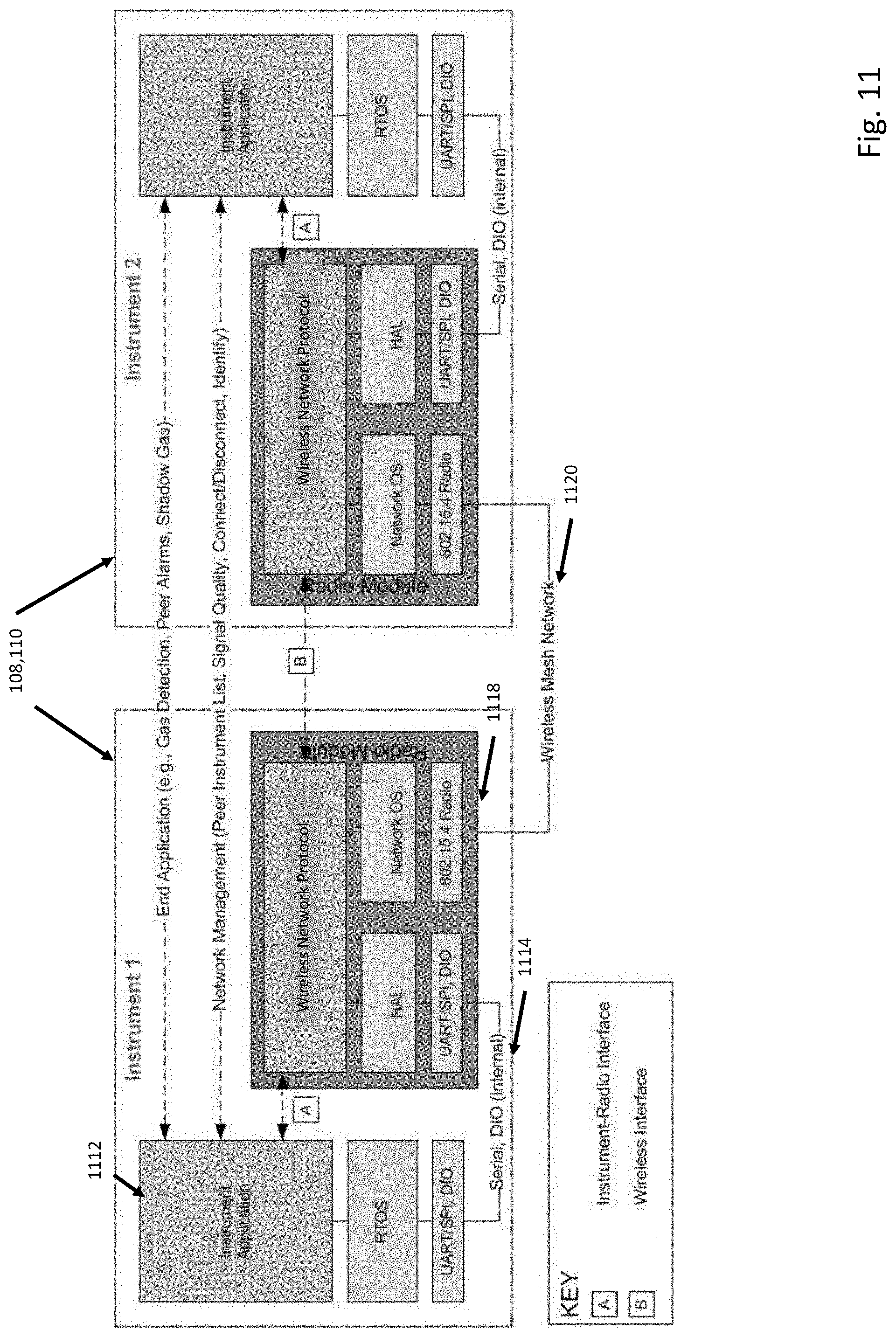
D00013
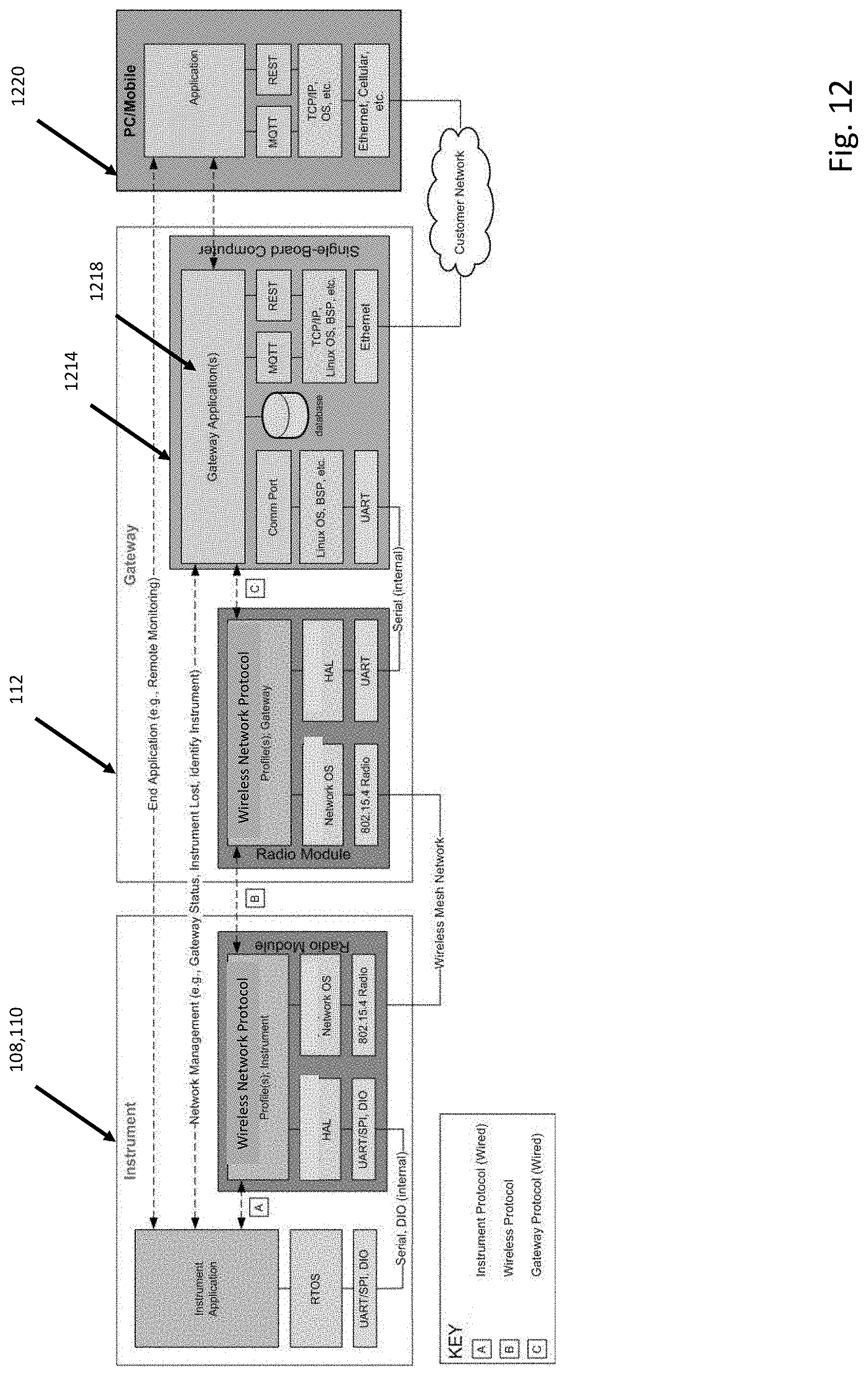
D00014

D00015
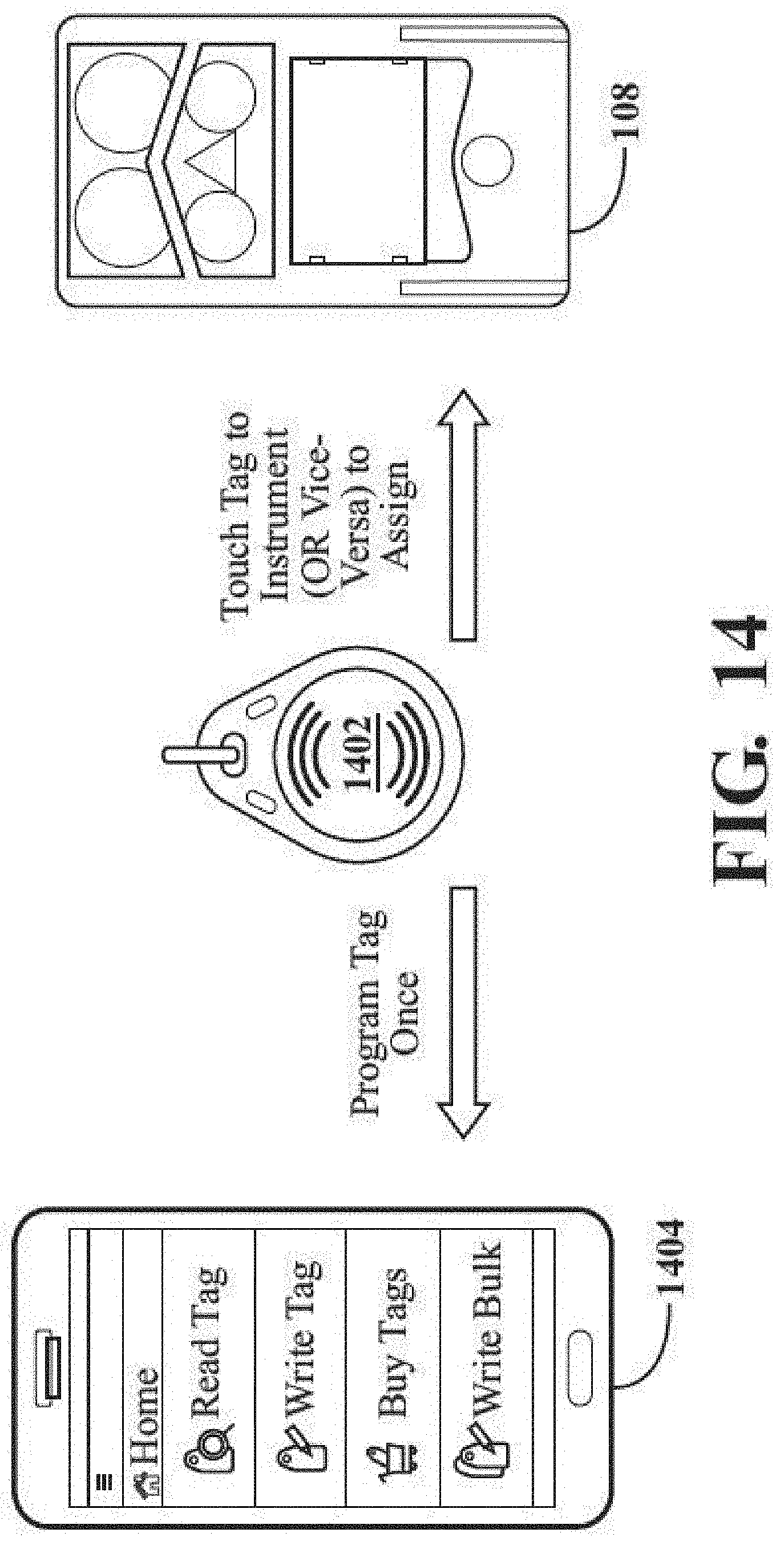
D00016
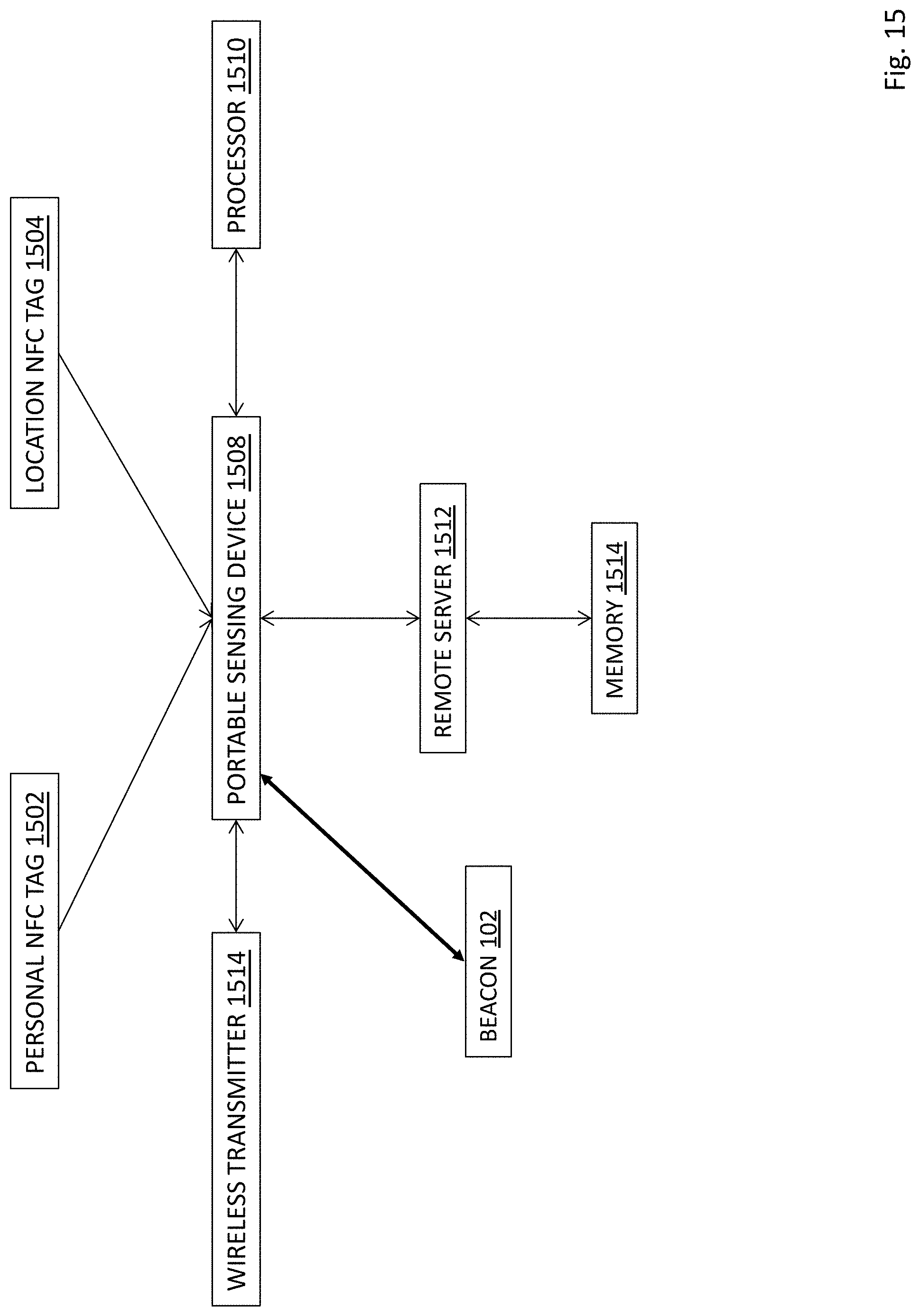
D00017
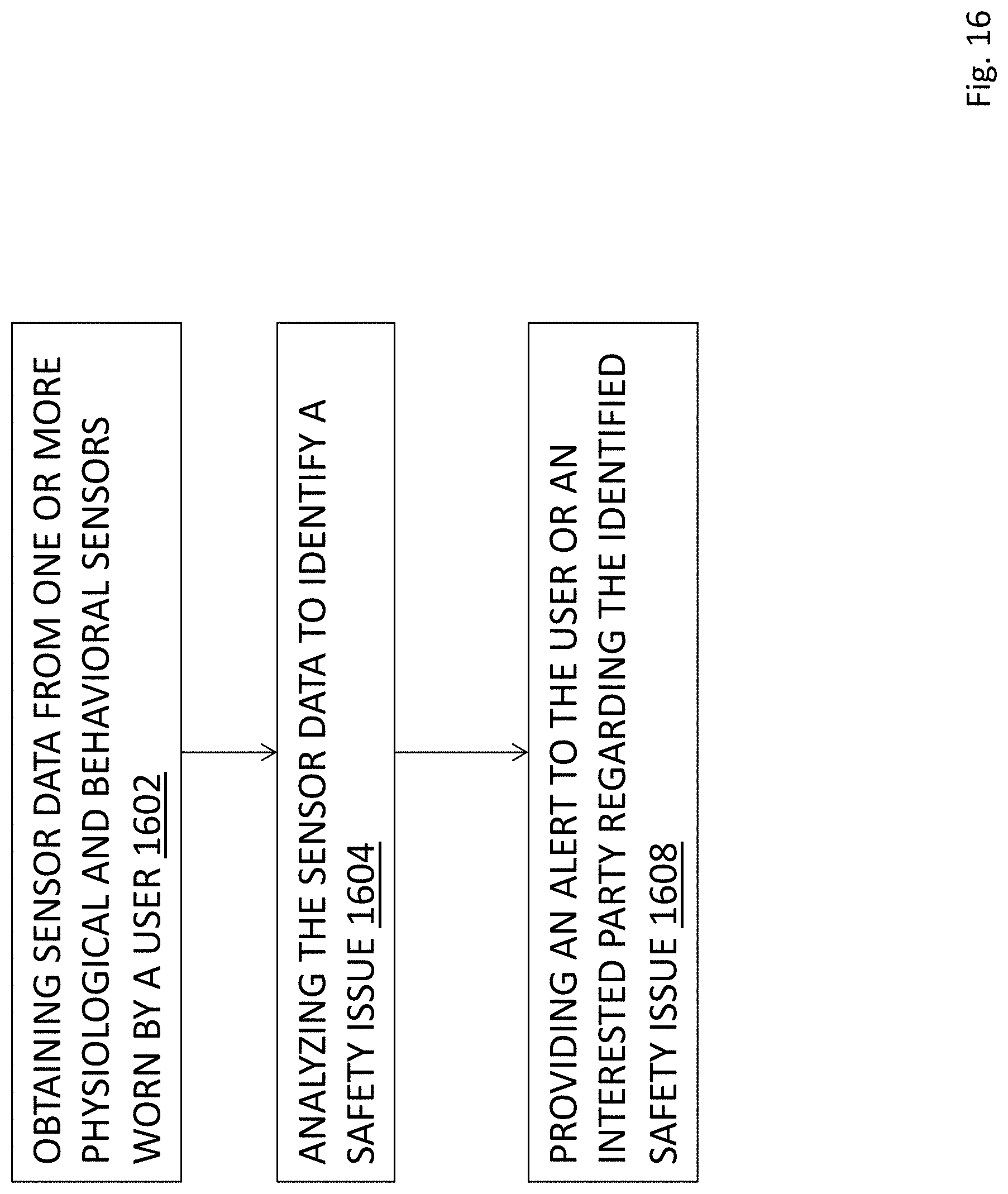


XML
uspto.report is an independent third-party trademark research tool that is not affiliated, endorsed, or sponsored by the United States Patent and Trademark Office (USPTO) or any other governmental organization. The information provided by uspto.report is based on publicly available data at the time of writing and is intended for informational purposes only.
While we strive to provide accurate and up-to-date information, we do not guarantee the accuracy, completeness, reliability, or suitability of the information displayed on this site. The use of this site is at your own risk. Any reliance you place on such information is therefore strictly at your own risk.
All official trademark data, including owner information, should be verified by visiting the official USPTO website at www.uspto.gov. This site is not intended to replace professional legal advice and should not be used as a substitute for consulting with a legal professional who is knowledgeable about trademark law.