Dome Screen Projection System
LIU; Kuan-Chih ; et al.
U.S. patent application number 16/502820 was filed with the patent office on 2020-05-28 for dome screen projection system. The applicant listed for this patent is BROGENT TECHNOLOGIES INC.. Invention is credited to Chih-Yung HSU, Kuan-Chih LIU, Pei-Te SU, Ping-Hsiu WU.
| Application Number | 20200166830 16/502820 |
| Document ID | / |
| Family ID | 67163849 |
| Filed Date | 2020-05-28 |
| United States Patent Application | 20200166830 |
| Kind Code | A1 |
| LIU; Kuan-Chih ; et al. | May 28, 2020 |
DOME SCREEN PROJECTION SYSTEM
Abstract
A dome screen projection system includes a dome screen unit and two sets of projectors. The dome screen unit includes a top side, two opposite lateral sides extending downward from two opposite ends of the top side, and a curved projection surface extending downwardly from the top side between the opposite lateral sides. Each of the two sets of projectors are disposed on the top side proximally to one of the lateral sides. The two sets of projectors are directed toward the curved projection surface.
| Inventors: | LIU; Kuan-Chih; (Kaohsiung, TW) ; HSU; Chih-Yung; (Kaohsiung, TW) ; WU; Ping-Hsiu; (Kaohsiung, TW) ; SU; Pei-Te; (Kaohsiung, TW) | ||||||||||
| Applicant: |
|
||||||||||
|---|---|---|---|---|---|---|---|---|---|---|---|
| Family ID: | 67163849 | ||||||||||
| Appl. No.: | 16/502820 | ||||||||||
| Filed: | July 3, 2019 |
| Current U.S. Class: | 1/1 |
| Current CPC Class: | G03B 37/00 20130101; G09B 27/00 20130101; G03B 21/56 20130101; G09B 9/32 20130101; G03B 21/14 20130101 |
| International Class: | G03B 21/56 20060101 G03B021/56; G03B 21/14 20060101 G03B021/14; G09B 27/00 20060101 G09B027/00; G03B 37/00 20060101 G03B037/00 |
Foreign Application Data
| Date | Code | Application Number |
|---|---|---|
| Nov 23, 2018 | TW | 107141784 |
Claims
1. A dome screen projection system, comprising: a dome screen unit including a top side, two opposite lateral sides extending downward from two opposite ends of said top side, and a curved projection surface extending downwardly from said top side between said opposite lateral sides; and at least two sets of projectors, each of said at least two sets of projectors being disposed on said top side proximally to one of said lateral sides, said at least two sets of projectors being directed toward said curved projection surface.
2. The dome screen projection system as claimed in claim 1, further comprising at least two platforms disposed on said top side and respectively proximal to said two opposite ends of said top side, said at least two sets of projectors being respectively mounted on said at least two platforms.
3. The dome screen projection system as claimed in claim 2, wherein each of said platforms is located within a section of said top side that begins from one of said two opposite ends of said top side and extends in a direction toward a mid part of said top side and that has a length equal to one fourth a full length of said top side.
4. The dome screen projection system as claimed in claim 2, wherein each of said at least two sets of projectors includes one pair of projectors, said one pair of projectors being mounted on one of said platforms.
5. The dome screen projection system as claimed in claim 3, wherein each of said at least two sets of projectors includes one pair of projectors, said one pair of projectors being mounted on one of said platforms.
6. The dome screen projection system as claimed in claims 5, wherein said top side of said dome screen unit is curved along a curve line that corresponds to a segment of a circle.
7. The dome screen projection system as claimed in claim 1, further comprising at least two ladders that are disposed at a back side of said dome screen unit oppositely of said curved projection surface, and that respectively extend upwardly to said at least two platforms from a bottom of said dome screen unit.
8. The dome screen projection system as claimed in claim 1, wherein said dome screen unit further includes a curved screen panel having said curved projection surface, and a support supporting said curved screen panel oppositely of said curved projection surface, both of said curved screen panel and said support extending downwardly from said top side of said dome screen unit between said two opposite lateral sides of said dome screen unit.
Description
CROSS-REFERENCE TO RELATED APPLICATION
[0001] This application claims priority to Taiwanese Patent Application No. 107141784, filed on Nov. 23, 2018.
FIELD
[0002] The disclosure relates to a screen projection system, and more particularly to a dome screen projection system.
BACKGROUND
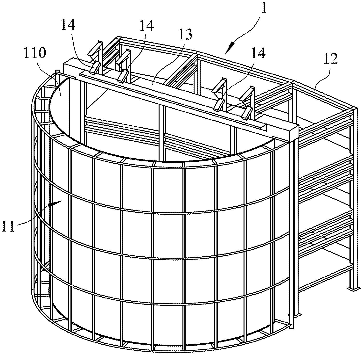
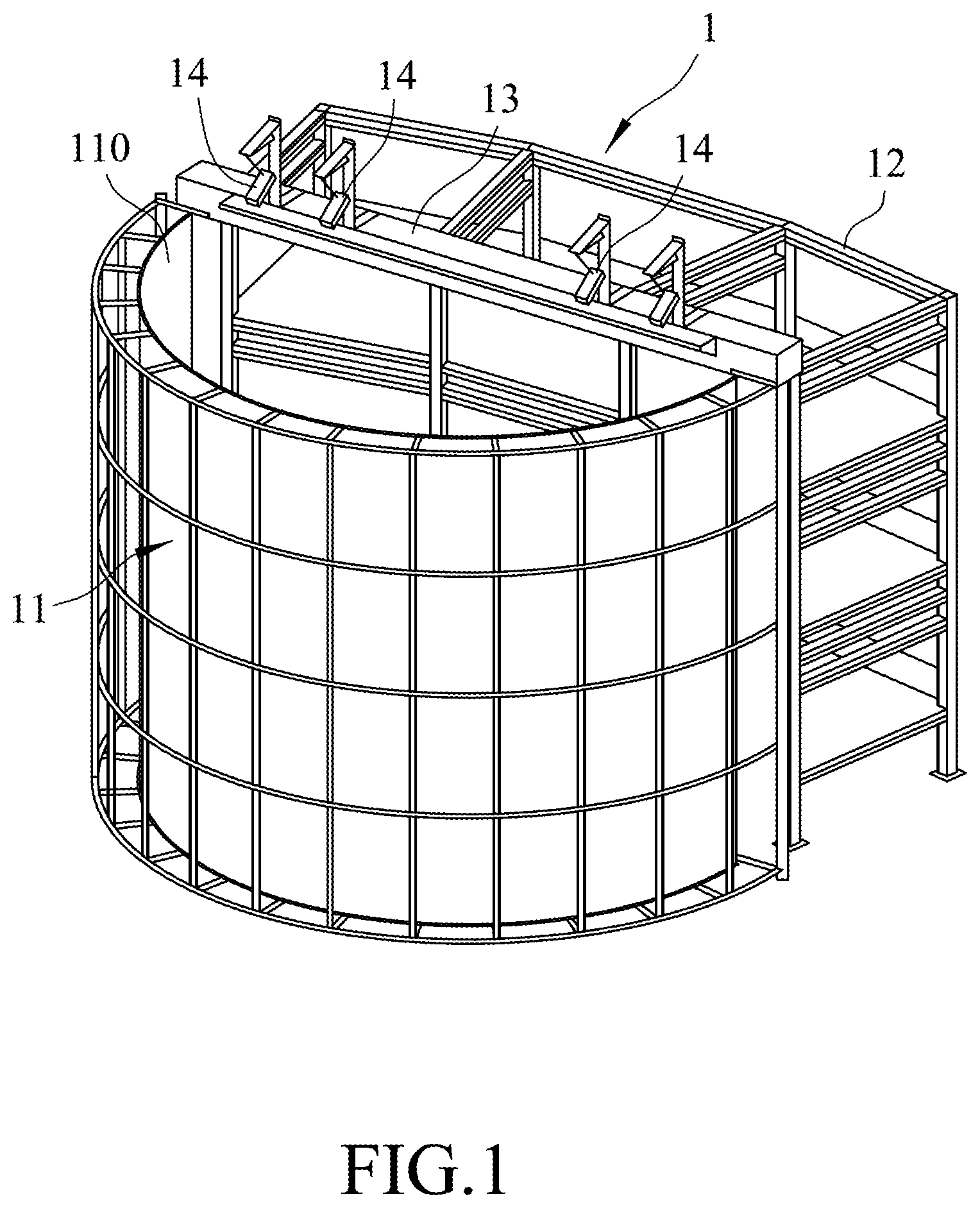
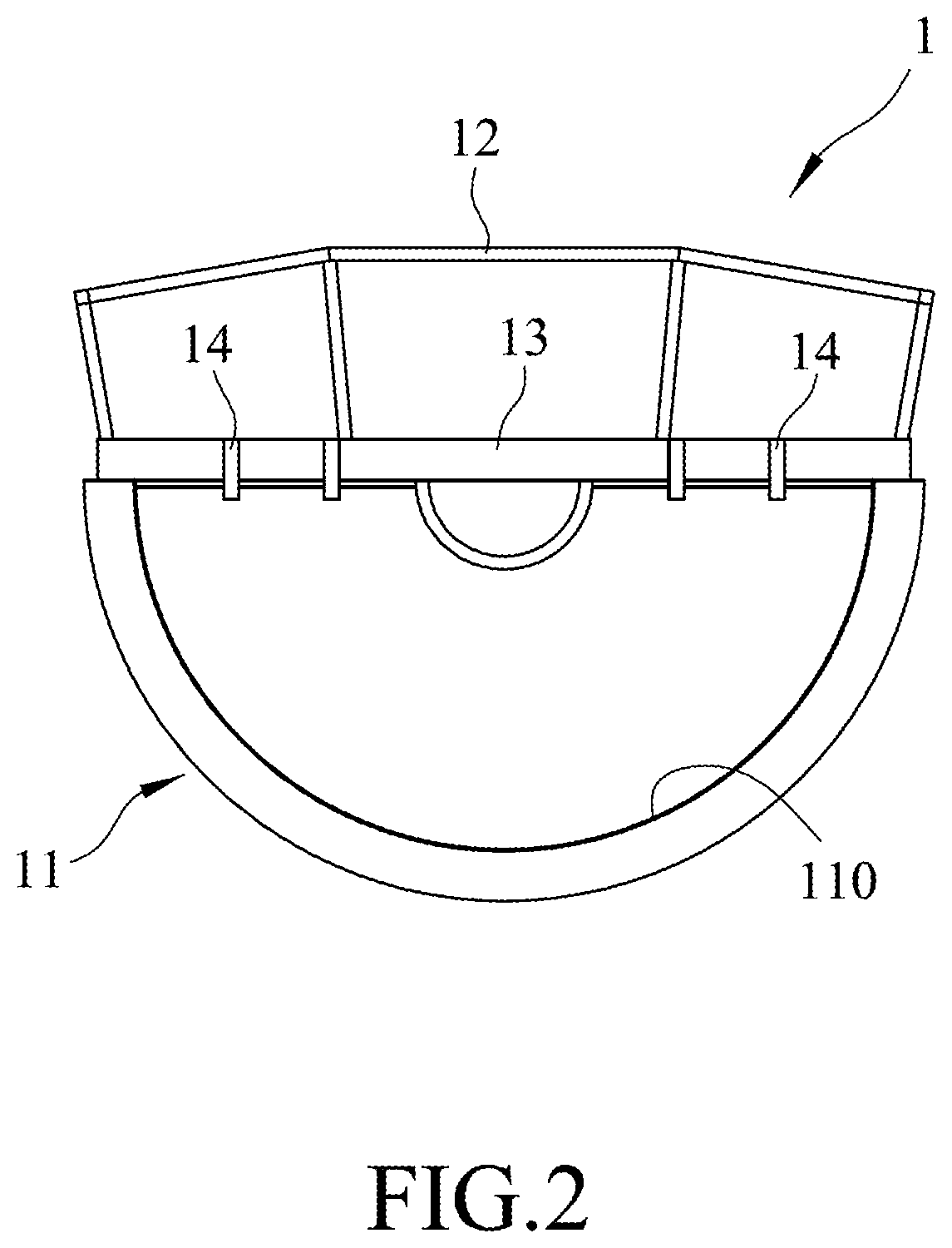
[0003] As shown in FIGS. 1 and 2, a conventional dome screen projection system 1 installed inside a building (not shown) includes a dome screen unit 11 having a projection surface 110, a steel support structure 12 disposed in front of the projection surface 110, a catwalk 13 disposed on a top side of the steel support structure 12, and a plurality of projectors 14 disposed on the catwalks 13 and directed to the projection surface 110. Providing the catwalk 13 in addition to the dome screen unit 11 needed for constructing the conventional dome screen projection system 1 can cause uncertainty of whether the catwalk 13 can be integrated with the building (not shown) or the steel support structure 12. Further, the conventional dome screen projection system 1 occupies a relatively large space, and requires extra time for installation. In case different working teams are responsible for the dome screen unit 11 and the catwalk 13, it is hard to coordinate designs of the dome screen unit 11 and the catwalk 13. In addition, working on the catwalks 13 during installation and maintenance is dangerous for workers and is prone to safety problems.
SUMMARY
[0004] Therefore, an object of the disclosure is to provide a dome screen projection system that need not provide an extra steel support structure and a catwalk.
[0005] According to the disclosure, a dome screen projection system includes a screen unit and at least two sets of projectors.
[0006] The dome screen unit includes a top side, two opposite lateral sides extending downward from two opposite ends of the top side, and a curved projection surface extending downwardly from the top side between the opposite lateral sides.
[0007] Each of the at least two sets of projectors are disposed on the top side proximally to one of the lateral sides. The at least two sets of projectors are directed toward the curved projection surface.
BRIEF DESCRIPTION OF THE DRAWINGS
[0008] Other features and advantages of the disclosure will become apparent in the following detailed description of the embodiment with reference to the accompanying drawings, of which:
[0009] FIG. 1 is a perspective view of a conventional dome screen projection system;
[0010] FIG. 2 is a top view of the conventional dome screen projection system;
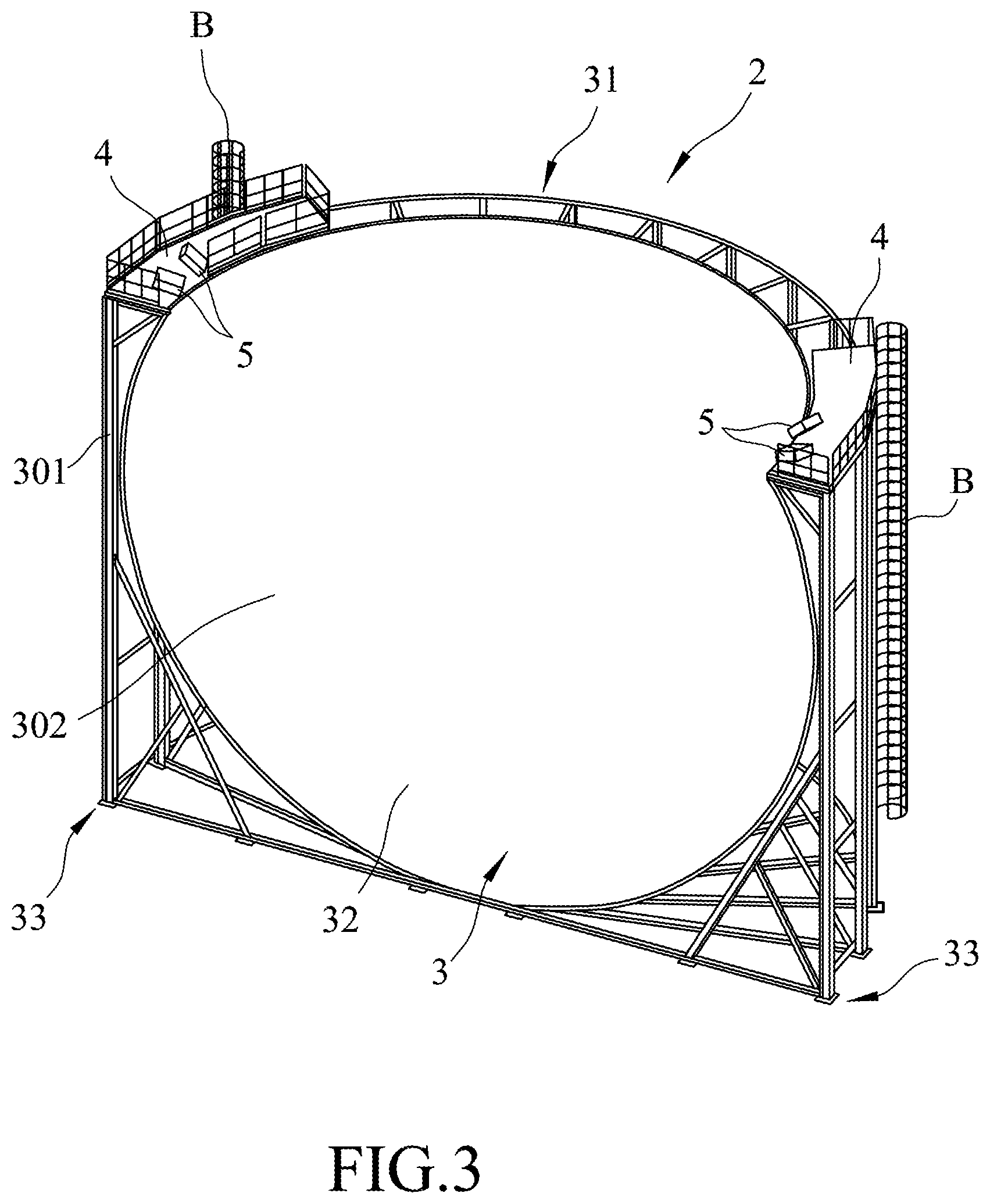
[0011] FIG. 3 is a perspective view of an embodiment of a dome screen projection system according to the disclosure; and
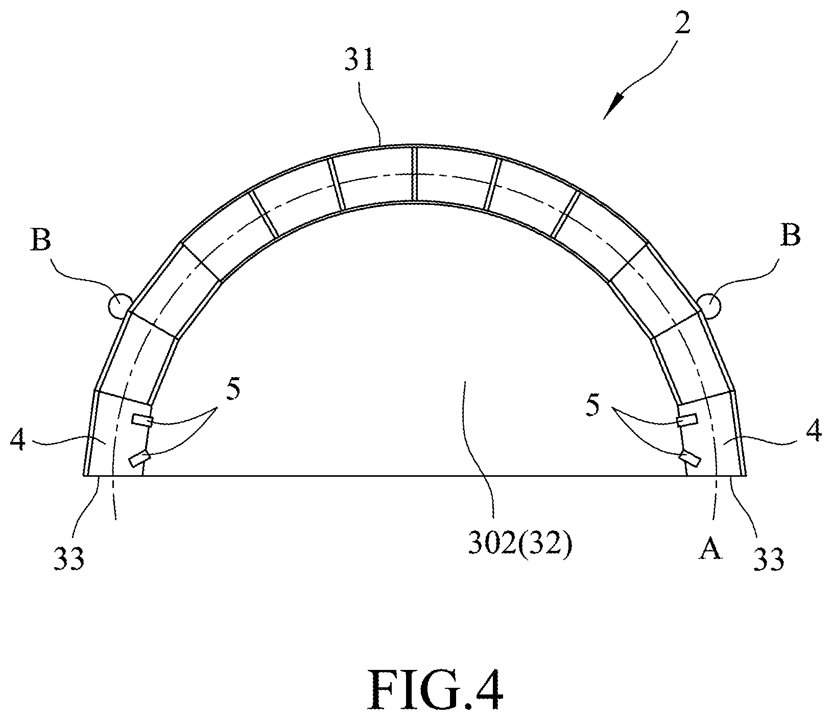
[0012] FIG. 4 is a top view of the embodiment.
DETAILED DESCRIPTION
[0013] FIGS. 3 and 4 illustrate an embodiment of a dome screen projection system 2 according to the disclosure for placement in a building structure (not shown). The dome screen projection system 2 includes a dome screen unit 3, two platforms 4, and two sets of projectors 5.
[0014] The dome screen unit 3 includes a top side 31, two opposite lateral sides 33, a curved screen panel 302 and a support 301. The top side 31 is curved along a curve line (A) that corresponds to a segment of a circle. The two opposite lateral sides 33 extend downward from two opposite ends of the top side 31. Both of the curved screen panel 302 and the support 301 extend downwardly from the top side 31 of the dome screen unit 3 between the two opposite lateral sides 33 of the dome screen unit 3. The curved screen panel 302 has a curved projection surface 32 extending downwardly from the top side 31 between the two opposite lateral sides 33. The curved projection surface 32 has a shape substantially corresponding to a segmented curved surface of a sphere. The support 301 supports the curved screen panel 30 oppositely of the curved projection surface 32.
[0015] The two platforms 4 are disposed on the top side 31 and are respectively proximal to the two opposite ends of the top side 31. In this embodiment, each of the platforms 4 is located within a section of the top side 31 that begins from one of the two opposite ends of the top side 31 and extends in a direction toward a mid part of the top side 31 and that has a length which is equal to one fourth a full length of the top side 31.
[0016] Each of the two sets of projectors 5 includes one pair of projectors 5. The pair of projectors 5 are mounted on one of the platforms 4, and are directed toward the curved projection surface 32. The directions of the projectors 5 generally intersect each other.
[0017] Noteworthily, arrangements and quantities of the platforms 4 and the projectors 5 are not limited in this embodiment. Based on the size of the dome screen unit 3 and the requirements of image projection, different numbers of the platforms 4 can be disposed on different sections of the top side 31. Further, there can be different numbers of the projectors 5 to be mounted on each platform 4. In addition, when the platforms 4 are not provided, the projectors 5 may be hung on the top side 41.
[0018] In this embodiment, because the projectors 5 and the platforms 4 are directly disposed on the dome screen unit 3, there is no need to install the extra steel structure 12 and/or the catwalk 13 used in the conventional dome screen unit, thereby eliminating the problem of uncertainty about the integration of the catwalk 13 encountered in the prior art. By virtue of the dome screen projection system 2 of the embodiment which dispenses with any extra steel support structure and catwalk, labor forces, occupied space, equipment costs and time cost can be saved.
[0019] In the conventional dome screen projection system, not only do the catwalk have to be additionally provided, but a worker also has to walk a distance for reaching the projectors. Because the catwalk is hung in air, there may be a high incidence of safety problem in that the worker falls from the catwalk during maintenance or construction. In place of the catwalk, the dome screen projection system 2 of the embodiment is provided with two ladders (B) that are disposed at a back side of the dome screen unit 3 oppositely of the curved projection surface 32, and that respectively extend upwardly to the two platforms 4 from a bottom of the dome screen unit 3. Each platform 4 may be provided with hanging racks (not shown) for hanging tools and other essential things usable for maintenance and construction. The ladders (B) allow workers to climb to the platforms 4 and the workers can easily reach the hanging racks to obtain their necessary tools without walking a long distance on the platforms 4. Therefore, levels of conveniences and safeness may be enhanced.
[0020] Because each pair of projectors 5 are mounted on one of the platforms 4 in the embodiment, in comparison with the projectors mounted on the catwalks 13 of the conventional dome screen projection system, a distance between the projectors 5 of the embodiment is shortened to balance brightness of projection lights in an overlap area, thereby reducing difficulties of image fusion for enhancing imaging quality. In addition, the effects of image fusion can also be enhanced by disposing the two sets of projectors 5 respectively on the two sections of the top side 31, which are respectively proximal to the lateral sides 33 of the dome screen unit 3, and whose lengths are equal to one fourth of the full length of the top side 31. However, the disclosure is not limited only to the embodiment.
[0021] In the description above, for the purposes of explanation, numerous specific details have been set forth in order to provide a thorough understanding of the embodiment. It will be apparent, however, to one skilled in the art, that one or more other embodiments may be practiced without some of these specific details. It should also be appreciated that reference throughout this specification to "one embodiment," "an embodiment," an embodiment with an indication of an ordinal number and so forth means that a particular feature, structure, or characteristic may be included in the practice of the disclosure. It should be further appreciated that in the description, various features are sometimes grouped together in a single embodiment, figure, or description thereof for the purpose of streamlining the disclosure and aiding in the understanding of various inventive aspects, and that one or more features or specific details from one embodiment may be practiced together with one or more features or specific details from another embodiment, where appropriate, in the practice of the disclosure.
[0022] While the disclosure has been described in connection with what is considered the exemplary embodiment, it is understood that this disclosure is not limited to the disclosed embodiment but is intended to cover various arrangements included within the spirit and scope of the broadest interpretation so as to encompass all such modifications and equivalent arrangements.
* * * * *
D00000
D00001
D00002
D00003
D00004
XML
uspto.report is an independent third-party trademark research tool that is not affiliated, endorsed, or sponsored by the United States Patent and Trademark Office (USPTO) or any other governmental organization. The information provided by uspto.report is based on publicly available data at the time of writing and is intended for informational purposes only.
While we strive to provide accurate and up-to-date information, we do not guarantee the accuracy, completeness, reliability, or suitability of the information displayed on this site. The use of this site is at your own risk. Any reliance you place on such information is therefore strictly at your own risk.
All official trademark data, including owner information, should be verified by visiting the official USPTO website at www.uspto.gov. This site is not intended to replace professional legal advice and should not be used as a substitute for consulting with a legal professional who is knowledgeable about trademark law.