Hollow-Core Photonic Crystal Fiber and Method of Manufacturing thereof
BAUERSCHMIDT; Sebastian ; et al.
U.S. patent application number 16/611350 was filed with the patent office on 2020-05-28 for hollow-core photonic crystal fiber and method of manufacturing thereof. This patent application is currently assigned to Max-Planck-Gesellschaft zur Forderung der Wissenschaften e.V. The applicant listed for this patent is Max-Planck-Gesellschaft zur Forderung der Wissenschaften e.V. Invention is credited to Sebastian BAUERSCHMIDT, Philip St. J. RUSSELL, Patrick Sebastian UEBEL.
| Application Number | 20200166699 16/611350 |
| Document ID | / |
| Family ID | 58715026 |
| Filed Date | 2020-05-28 |


| United States Patent Application | 20200166699 |
| Kind Code | A1 |
| BAUERSCHMIDT; Sebastian ; et al. | May 28, 2020 |
Hollow-Core Photonic Crystal Fiber and Method of Manufacturing thereof
Abstract
A hollow-core photonic crystal fiber (HC-PCF)(10) for guiding at least one mode of a light field(1) along a mode guiding section(11) of the HC-PCF(10), comprises an outer jacket(12), an inner cladding(13) and a hollow core(14), which extend along the HC-PCF(10), wherein the inner clad-ding(13) is arranged on an interior surface of the outer jacket(12) and comprises anti-resonant structures(15) surrounding the hollow core(14), and the hollow core(14) has a mode guiding core diameter(d) provided along the mode guiding section of the HC-PCF(10), and wherein at least one fiber end (16) of the HC-PCF(10) has a light field coupling section(17) in which the hollow core(14) is tapered over an axial coupling section length from a fiber end core diameter(D) at the at least one fiber end (16) to the mode guiding core diameter(d). Furthermore, methods of using the HC-PCF and manufacturing the HC-PCF are described.
| Inventors: | BAUERSCHMIDT; Sebastian; (Wendelstein, DE) ; UEBEL; Patrick Sebastian; (Marloffstein, DE) ; RUSSELL; Philip St. J.; (Rottenbach, DE) | ||||||||||
| Applicant: |
|
||||||||||
|---|---|---|---|---|---|---|---|---|---|---|---|
| Assignee: | Max-Planck-Gesellschaft zur
Forderung der Wissenschaften e.V Munchen DE |
||||||||||
| Family ID: | 58715026 | ||||||||||
| Appl. No.: | 16/611350 | ||||||||||
| Filed: | May 7, 2018 | ||||||||||
| PCT Filed: | May 7, 2018 | ||||||||||
| PCT NO: | PCT/EP2018/061674 | ||||||||||
| 371 Date: | November 6, 2019 |
| Current U.S. Class: | 1/1 |
| Current CPC Class: | G02B 6/02328 20130101; G02B 6/02304 20130101; G02B 6/2552 20130101 |
| International Class: | G02B 6/02 20060101 G02B006/02; G02B 6/255 20060101 G02B006/255 |
Foreign Application Data
| Date | Code | Application Number |
|---|---|---|
| May 17, 2017 | EP | 17171468.6 |
Claims
1.-18. (canceled)
19. A hollow-core photonic crystal fiber (HC-PCF), being configured for guiding at least one mode of a light field along a mode guiding section of the HC-PCF, comprising: an outer jacket, an inner cladding and a hollow core, that extend along the HC-PCF, wherein the inner cladding is arranged on an interior surface of the outer jacket and comprises anti-resonant structures surrounding the hollow core, and the hollow core has a mode guiding core diameter (d) provided along the mode guiding section of the HC-PCF, characterized in that at least one fiber end of the HC-PCF has a light field coupling section in which the hollow core is tapered over an axial coupling section length from a fiber end core diameter (D) at the at least one fiber end to the mode guiding core diameter (d).
20. The hollow-core photonic crystal fiber of claim 19, wherein: the anti-resonant structures have a cross-sectional dimension that gradually increases in the light field coupling section towards the mode guiding section.
21. The hollow-core photonic crystal fiber of claim 19, wherein: the fiber end core diameter (D) and the axial coupling section length are selected such that an overlap of the inner cladding and the light field to be focussed to the hollow core for guiding by the HC-PCF is excluded or negligible at the fiber end.
22. The hollow-core photonic crystal fiber of claim 19, wherein: an axial transition length over which the fiber core diameter dimension reduces in the light field coupling section from the fiber end core diameter (D) to (0.5*(D+d)) is at least 0.5 times the mode guiding core diameter (d) and/or at most 0.5 times a transition dimension (.pi.(D.sup.2d.sup.2-d.sup.4).sup.0.5/(4.lamda.)), where .lamda. is the central wavelength of the light field.
23. The hollow-core photonic crystal fiber of claim 22, wherein: the axial transition length is at least 10 .mu.m and/or at most 1000 .mu.m.
24. The hollow-core photonic crystal fiber of claim 19, wherein: the axial coupling section length of the light field coupling section is at least the mode guiding core diameter (d) and/or at most a transition dimension (.pi.(D.sup.2d.sup.2-d.sup.4).sup.0.5/(4.lamda.)), where .lamda. is the central wavelength of the light field.
25. The hollow-core photonic crystal fiber of claim 24, wherein: the axial coupling section length of the light field coupling section is at least 20 .mu.m and/or at most 5000 .mu.m.
26. The hollow-core photonic crystal fiber of claim 19, wherein: the anti-resonant structures have rounded ends facing toward the at least one fiber end.
27. The hollow-core photonic crystal fiber of claim 19, wherein: the inner cladding extends to the opening of the at least one fiber end.
28. The hollow-core photonic crystal fiber of claim 19, wherein: the inner cladding does not extend to the opening of the at least one fiber end.
29. The hollow-core photonic crystal fiber of claim 19, wherein: the light field coupling section is provided at an incoupling end of the HC-PCF only.
30. The method of using the hollow-core photonic crystal fiber of claim 19, wherein: the HC-PCF is used for subjecting a light field to an optically non-linear process, in particular spectral broadening, or the HC-PCF is used for delivering a light field to an application site.
31. The method of manufacturing the hollow-core photonic crystal fiber of claim 19, comprising the steps of: providing a HC-PCF including the outer jacket and the inner cladding, and forming the light field coupling section by thermal treatment of the HC-PCF.
32. The method of claim 31, comprising the steps of: subjecting at least one fiber section of the HC-PCF to the thermal treatment, and cutting the HC-PCF in the at least one thermally treated fiber section and with a distance thereof to a predetermined fiber length for forming the light field coupling section at the at least one fiber end.
33. The method of claim 31, comprising the steps of: cutting the HC-PCF to a predetermined fiber length to be obtained, and subjecting at least one fiber end of the cut HC-PCF to the thermal treatment for forming the light field coupling section at the at least one fiber end.
34. The method of claim 32, wherein: the thermal treatment comprises a heating of the HC-PCF such that the resonant structures of the inner cladding are softened and the light field coupling section is formed by the effect of surface tension in the softened anti-resonant structures.
35. The method of claim 32, wherein: the thermal treatment comprises a heating of the HC-PCF such that the resonant structures of the inner cladding are softened and the light field coupling section is formed by the combined effect of surface tension in the softened anti-resonant structures and an applied vacuum in at least one of the anti-resonant structures.
36. The method of claim 32, wherein: the thermal treatment comprises a heating of the HC-PCF such that the resonant structures of the inner cladding are softened and the light field coupling section is formed by the combined effect of surface tension in the softened anti-resonant structures and an applied pressure in the mode guiding core.
Description
[0001] The invention relates to a hollow-core photonic crystal fiber (HC-PCF), in particular of non-bandgap type (or: hollow-core anti-resonant-reflecting fibre, HC-AF), in particular having an axial hollow core and an inner cladding region comprising an arrangement of anti-resonant structures surrounding the core, and being configured in particular for guiding at least one mode of a light field. Furthermore, the invention relates to methods of using the HC-PCF and manufacturing the HC-PCF. Applications of the invention are available e. g. in the fields of optical metrology, spectroscopy, scientific research and light guiding.
[0002] In the present specification, reference is made to the following prior art illustrating the technical background of the invention: [0003] [1] P. Uebel et al. in "Opt. Lett." 41, 1961-1964 (2016); [0004] [2] F. Benabid et al. in "Science" 298, 399-402 (2002); [0005] [3] WO 2015/185761 A1; [0006] [4] P. St. J. Russell et al. in "Nature Photonics" 8, 278-286 (2014); and [0007] [5] EP 1 153 324 B2.
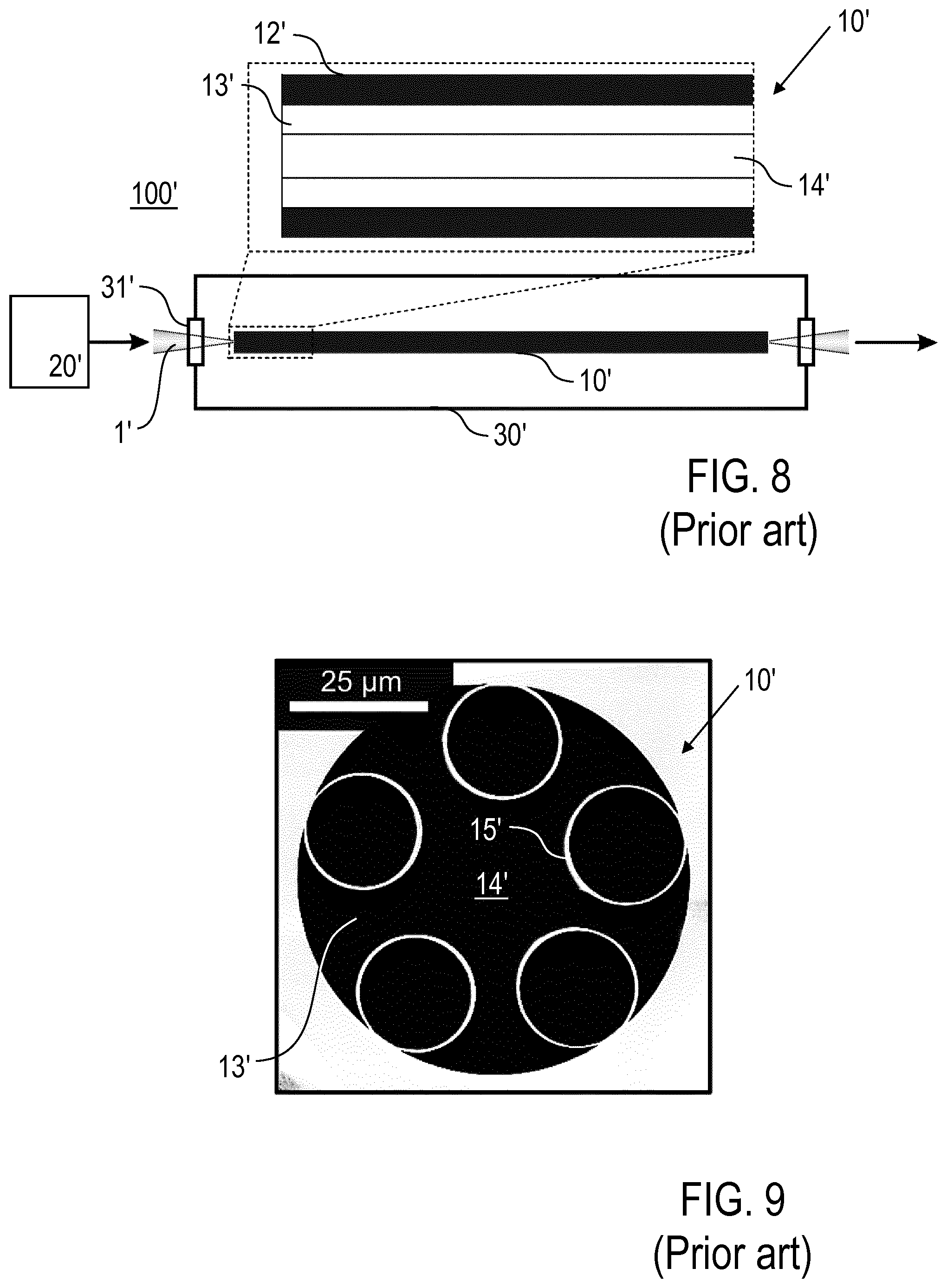
[0008] Gas-filled hollow-core photonic crystal fibers are a technology platform for a new generation of high-brightness light sources with potential applications e. g. in metrology and spectroscopy. FIG. 8 (prior art) schematically shows the concept of such a light source 100' based on nonlinear optics in a gas-filled HC-PCF 10'. The HC-PCF 10' includes an outer jacket 12', an inner cladding 13' and a hollow core 14' (see longitudinal cross-section of HC-PCF 10' in top of FIG. 8). The inner cladding 13' comprises anti-resonant structures 15', like a single ring arrangement of tube-shaped capillaries axially extending along the HC-PCF 10' and surrounding the hollow core 14' as exemplified in the cross-sectional scanning electron microscope (SEM) image of FIG. 9 (prior art) and disclosed e. g. in [1]. Other fiber structures can be more complex, such as Kagome-type or nested structures [2, 3].
[0009] A pulse light field 1' from a pump source 20' is launched at the incoupling end into the core 14' of the HC-PCF 10' and excites predominantly the fundamental transverse mode which is guided towards the outcoupling end. The HC-PCF 10' is placed in a gas cell 30' providing a controlled gas environment (e.g. noble gases or Raman-active gases) at typical pressures of up to several 10's of bar and having transparent windows 31' for transmitting the light. The interplay between waveguide dispersion of the HC-PCF 10' and nonlinearity of the gas result in a strong modification of the pump pulse light field 1', which include e. g. pulse compression and spectral broadening [4] and/or other optically non-linear effects.
[0010] While the operation of the light source 100' of FIG. 8 has been proved in experiments, the following substantial disadvantage has been found. Lifetime tests by the inventors reveal that the average output power strongly degrades at a pump dose of already a few 10 Wh of exposure, severely limiting the usability of the HC-PCF-based light source 100' in practical routine applications. As a further disadvantage, the conventional HC-PCF can have a restricted launch efficiency when starting the nonlinear operation of the HC-PCF 10'.
[0011] The objective of the invention is to provide an improved hollow-core photonic crystal fiber and methods of manufacturing thereof being capable of avoiding disadvantages of conventional techniques. In particular, the HC-PCF is to be suitable for a linear or nonlinear operation with increased lifetime and/or increased light power and/or with improved launch efficiency. Furthermore, the HC-PCF is to be manufactured with uncomplicated processes.
[0012] These objectives are correspondingly solved by a HC-PCF and a method of manufacturing thereof comprising the features of the independent claims, respectively. Preferred embodiments and applications of the invention arise from the dependent claims.
[0013] According to a first general aspect of the invention, the above objective is solved by a HC-PCF having an outer jacket, an inner cladding and a hollow core, which extend along the axial length of the HC-PCF. The hollow core surrounded by the inner cladding provides a mode guiding section of the HC-PCF for guiding at least one mode, e. g. the fundamental transverse mode, of a light field (pump field) coupled at an incoupling end to the HC-PCF. The outer jacket is made of a solid material and the inner cladding is supported by an interior surface of the outer jacket. The inner cladding comprises anti-resonant structures extending along the axial length of the HC-PCF and delimiting the hollow core. Along the mode guiding section of the HC-PCF, the hollow core has a mode guiding core diameter (d). The mode guiding core diameter is the inscribed circular cross-sectional dimension of the hollow core inner clearance. Accordingly, the mode guiding section is adapted for guiding a light field with a certain central wavelength, i.e. there is a mutual relationship of the central wavelength of the light field and the corresponding focussing properties and in particular the mode guiding core diameter.
[0014] According to the invention, at least one fiber end of the HC-PCF has a light field coupling section in which the hollow core is tapered over an axial coupling section length from a fiber end core diameter (D) at the at least one fiber end to the mode guiding core diameter (d). The fiber end core diameter is a cross-sectional dimension of the hollow core inner clearance at the fiber end opening, and it is larger than the mode guiding core diameter.
[0015] The inventors have found that the lost in output power of conventional HC-PCFs is a result of a degradation of the fiber input face (opening of fiber end), in particular when using high power pump fields. The transverse structure of the conventional HC-PCF is typically constant along the fiber length. During a nonlinear experiment with low exposure to pump energy (e.g. a few Wh) the structure of the input side remains unchanged, i.e. no noticeable difference can be observed in a SEM. However, lifetime tests by the inventors reveal strong degradation of the fiber input face at a pump dose of already a few 10 Wh of exposure. Degradation limits the incoupling efficiency of the pump field, so that the output power of the HC-PCF is limited accordingly. The input face degradation is a result of field enhancement at the glass-gas boundary and plasma-based erosion caused by the strong sudden overlap of the pump field with the inner cladding of the conventional HC-PCF.
[0016] On the contrary, the light field coupling section at the at least one fiber end of the inventive HC-PCF provides another structure compared with the fiber end of a conventional HC-PCF being manufactured with a constant inner diameter at the fiber end. With the inventive provision of the light field coupling section, a smooth transition from zero or negligible field overlap between the pump field and the inner jacket, made of e. g. glass, at the fiber end to the mode overlap in the mode guiding section is created, resulting in reduced field enhancement and suppressed plasma-based erosion. Zero or negligible field overlap means that intensity of the pump field portions reaching the inner jacket is zero or below a critical intensity causing an inner jacket erosion. Advantageously, no degradation of the inventive HC-PCF is observed even for pump doses above 1000 Wh and the lifetime of the HC-PCF is increased accordingly. In addition to the enhanced lifetime, the launch efficiency was found to improve by a few % compared to the conventional HC-PCF.
[0017] According to second general aspect of the invention, the above objective is solved by methods of using the HC-PCF according to the first general aspect of the invention. The input light field parameters, in particular the intensity, central wavelength, focusing geometry and beam diameter thereof, are selected and the HC-PCF is dimensioned such that the HC-PCF can be operated without a degradation of the at least one fiber end. According to a first preferred application (nonlinear operation), the inventive HC-PCF is used for subjecting a light field to an optically non-linear process, in particular spectral broadening and/or pulse compression. Preferably, a light source for generating broadband output pulses (in particular covering a spectral range from the vacuum or deep ultraviolet (UV) to the near infrared (IR)) is provided which includes a pump source and the HC-PCF. The light source including the inventive HC-PCF is considered as a further independent subject of the invention.
[0018] According to a second preferred application (linear operation) of the invention, the HC-PCF is used for guiding a light field to an application site, e. g. for material processing.
[0019] According to third general aspect of the invention, the above objective is solved by a method of manufacturing the HC-PCF according to the first general aspect of the invention. The manufacturing method comprises the steps of providing a HC-PCF including the outer jacket, the inner cladding and the hollow core and forming an inner jacket tapering for providing the light field coupling section at at least one fiber end by a thermal treatment of the HC-PCF. Advantageously, the inventive HC-PCF is fabricated by locally heating the fibre to the softening point of the fiber material, preferably glass. Because of surface tension, the inner jacket structure, e. g. the capillaries thereof, tends to collapse while preferably the outer diameter of the HC-PCF almost remains unchanged.
[0020] According to a preferred embodiment of the invention, the anti-resonant structures have a cross-sectional dimension which gradually increases in the light field coupling section from the fiber end opening towards the mode guiding section. Advantageously, this embodiment of the HC-PCF has a modified structure of the inner cladding in the light field coupling section, while the outer diameter of the HC-PCF is constant along the light field coupling section, so that a modification of the outer jacket is avoided and e. g. coupling of the HC-PCF with a holding carrier is not affected.
[0021] According to a further preferred embodiment of the invention, the fiber end core diameter and the axial coupling section length of the light field coupling section are selected such that a field overlap of the inner cladding and the light field to be focussed to the hollow core for guiding by the HC-PCF is excluded or negligible at the fiber end opening. Advantageously, this provides a smooth transition to the field overlap of the inner cladding and the light field in the mode guiding section. Preferably a pump source and an optical setup are configured for maximum coupling efficiency of the light to the mode guiding section of the HC-PCF.
[0022] Advantageously, the light field coupling section can be characterized by at least one of the parameters including the axial coupling section length and an axial transition length. The axial coupling section length is the overall length of the light field coupling section. The light field coupling section preferably is characterized by the axial transition length, which is a fiber length over which the fiber core diameter dimension reduces in the light field coupling section from the fiber end core diameter (D) to (0.5*(D+d)).
[0023] The axial transition length preferably has a lower limit of at least 0.5 times the mode guiding core diameter (d) and/or an upper limit of at most 0.5 times a transition dimension (.pi.(D.sup.2d.sup.2-d.sup.4).sup.0.5/(4.lamda.)), where .lamda. is the central wavelength of the pump light field. These limits of the axial transition length have advantages in terms of a minimized but effective transition from the fiber end core diameter to the mode guiding core diameter. With the upper limit, the light field coupling section differs in particular from conventional up-tapering of optical fibers (described e. g. in [5]) which is designed for an adiabatic transition of the free space beam to the guided mode. Particularly preferred, the axial transition length is at least 10 .mu.m and/or at most 1000 .mu.m.
[0024] The axial coupling section length preferably has a lower limit of at least the mode guiding core diameter (d) and/or an upper limit of at most the transition dimension (.pi.(D.sup.2d.sup.2-d.sup.4).sup.0.5)/(4.lamda.)). Particular advantages for practical applications of the invention are obtained if the axial coupling section length of the light field coupling section is at least 20 .mu.m and/or at most 5000 .mu.m.
[0025] Preferably, the light field coupling section is configured such that no sharp (step- or blade shaped) edges of the inner cladding are exposed to the input pump field. Advantageously, field enhancements at edges of the inner cladding are avoided. However, it is not necessary to remove any sharp edges of the anti-resonant structures, in particular when they are moved out of the region with critical light field intensities.
[0026] According to a further preferred embodiment of the invention, the inner cladding extends to the opening of the at least one fiber end. Advantageously, a compact size of the light field coupling section is obtained. Alternatively, the inner cladding does not extend to the opening of the at least one fiber end. In other words, the inner cladding can be provided with an axial distance from the opening of the at least one fiber end. Advantageously, this allows a reduction of the inner cladding with a thickness down to zero within the HC-PCF.
[0027] The advantage of suppressing fiber end degradation is obtained not only at the incoupling fiber end of a HC-PCF, but also at the outcoupling end thereof. Thus, according to the invention, the light field coupling section can be provided at at least one of the incoupling and outcoupling fiber ends, e. g. at both ends. Preferably, the light field coupling section is provided exclusively at the incoupling end of the HC-PCF, so that the manufacturing of the HC-PCF is simplified in an advantageous manner.
[0028] According to a preferred variant of the HC-PCF manufacturing method, a length of a HC-PCF is thermally treated at at least one fiber section arranged with a distance from the ends of this HC-PCF. Due to the thermal treatment, tapering of the inner jacket is formed along the length of the HC-PCF. Subsequently, the HC-PCF is cut in the at least one thermally treated fiber section, e. g. in the centre thereof, and with a distance from the at least one thermally treated fiber section to a predetermined fiber length for forming the light field coupling section at the at least one fiber end. With the preferred provision of the light field coupling section at the incoupling end, the incoupling end is then prepared by carefully cleaving in the transition region to produce a high quality end-face. According to an alternative variant of the HC-PCF manufacturing method, the HC-PCF is cut to a predetermined fiber length to be obtained, and at least one fiber end of the cut HC-PCF is subjected to the thermal treatment for forming the light field coupling section at the at least one fiber end.
[0029] Appropriate thermal treatment conditions can be found by tests or numerical simulations of the thermal inner cladding deformation in response to heating, e. g. by surface tension. In particular, the thermal treatment conditions include the treatment temperature and a distribution thereof along a treatment range for forming the taper geometry to be obtained.
[0030] Preferably, the thermal treatment comprises a heating of the HC-PCF at the at least one fiber section or at the at least one fiber end, e. g. by laser irradiation, arc discharge, or by an external resistance heater, such that the resonant structures of the inner cladding are softened and the light field coupling section is formed by the effect of surface tension in the softened anti-resonant structures. Simultaneously with a contraction of the anti-resonant structures, the wall thickness thereof is increased. Additionally, a vacuum can be applied to the HC-PCF, in particular in the in anti-resonant structures of the inner cladding and the light field coupling section is formed by the combined effect of surface tension in the softened anti-resonant structures and the applied vacuum. Additionally or alternatively, an inner pressure can be applied in the mode guiding core, so that the light field coupling section is formed by the combined effect of surface tension in the softened anti-resonant structures and the applied pressure.
[0031] Further details and advantages of the invention are described in the following with reference to the attached drawings, which show in:
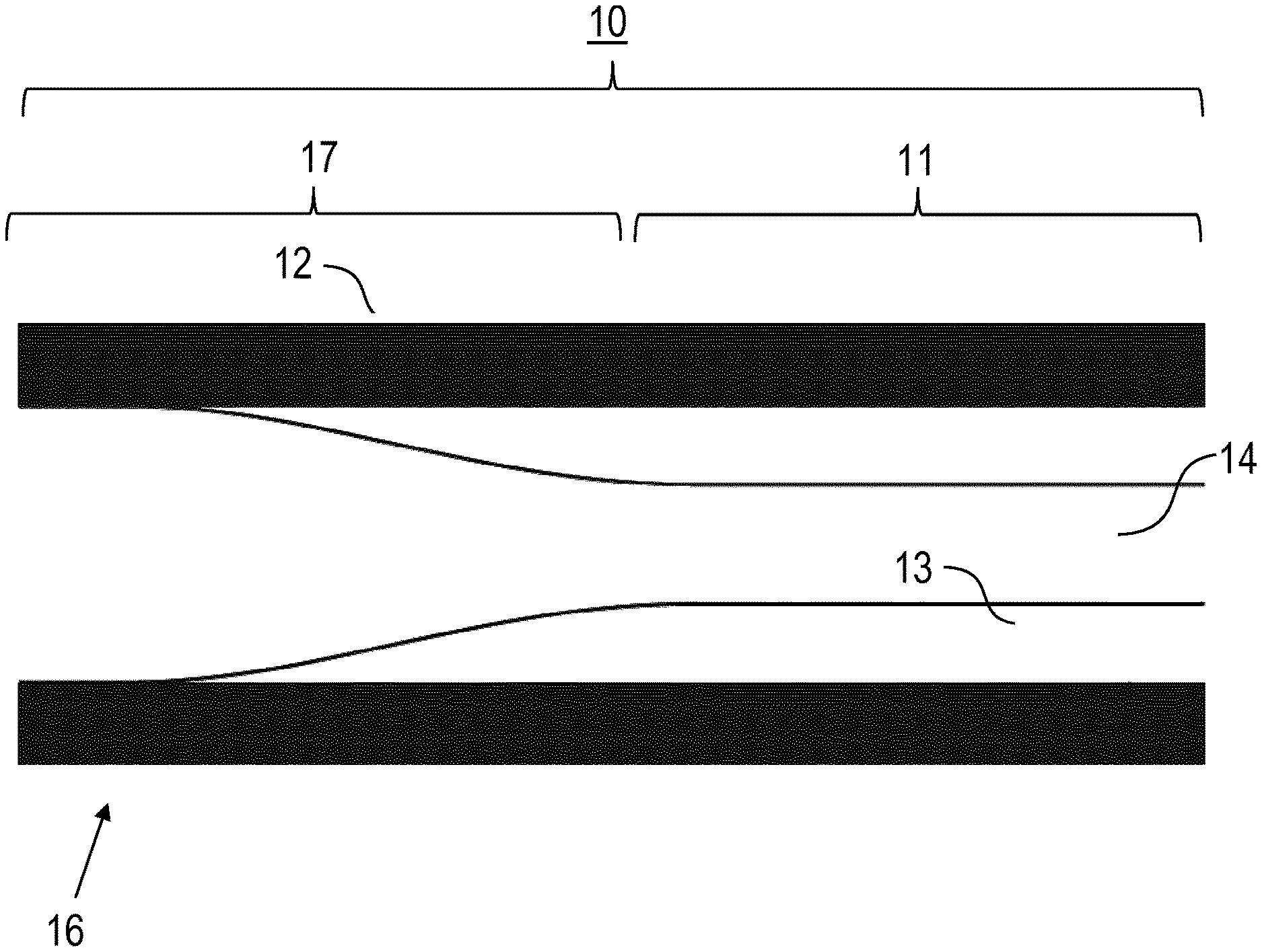
[0032] FIG. 1: a schematic cross-sectional view of a HC-PCF according to a preferred embodiment of the invention;
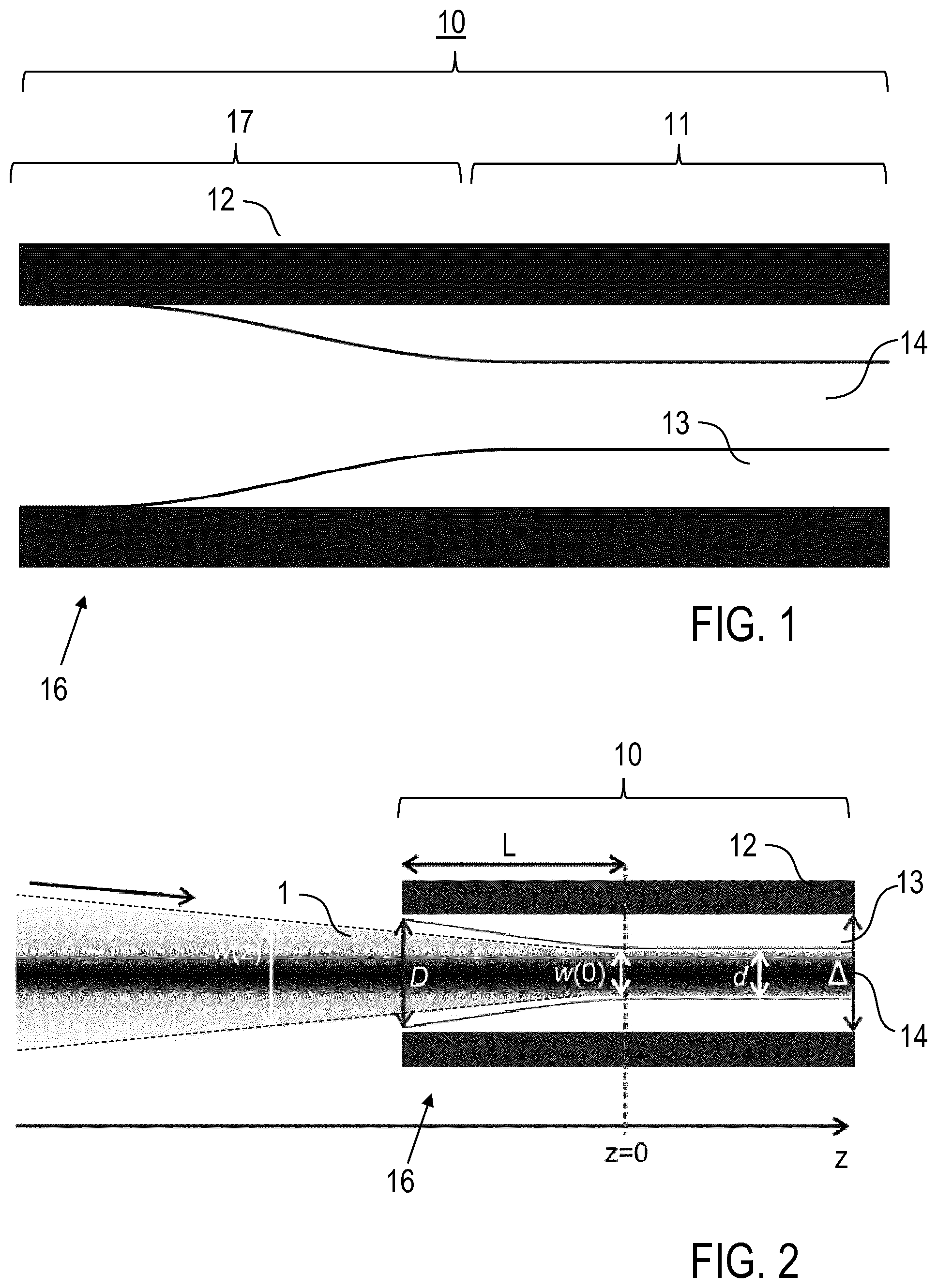
[0033] FIG. 2: a schematic cross-sectional view of a HC-PCF according to a further embodiment of the invention with an illustration of the pump light field;
[0034] FIG. 3: images of a fiber end of an inventive HC-PCF, including an optical micrograph (A) and a SEM image (B);
[0035] FIG. 4: SEM images of the input side of degraded conventional HC-PCFs;
[0036] FIG. 5: experimental results of measuring a HC-PCF output power of an inventive HC-PCF (curve A) and a conventional HC-PCF (curve B);
[0037] FIG. 6: a schematic illustration of a light source device including a HC-PCF according to the invention;
[0038] FIG. 7: a measured output spectrum of a HC-PCF according to the invention; and
[0039] FIGS. 8 and 9: a schematic illustration of a HC-PCF based light source including a conventional HC-PCF and an SEM image of the input side of a conventional HC-PCF.
[0040] Features of preferred embodiments of the invention are described in the following with reference to the provision of a light field coupling section at the input fiber end of a HC-PCF. The invention can be correspondingly implemented with a light field coupling section at the output fiber end or at both ends of the HC-PCF. Exemplary reference is made to a HC-PCF, wherein the inner cladding is formed by a single ring arrangement of tube-shaped capillaries. The invention can be correspondingly implemented with other anti-resonant structures, like Kagome-type or nested structures.
[0041] FIGS. 1 and 2 show schematic enlarged cross-sectional views of HC-PCFs 10 according to preferred embodiments of the invention. FIG. 2 illustrates a Gaussian beam (input light field 1) being focused and coupled to the HC-PCFs 10 (shown with the input fiber end only). For practical applications, the HC-PCFs 10 have a longer axial extension than shown in FIGS. 1 and 2, which, depending on the function of the HC-PCF 10, is selected in a range from e. g. 1 cm to 5 m or even more.
[0042] The HC-PCF 10 comprises an outer jacket 12 being made of e. g. quartz glass with a thickness of e. g. 30 .mu.m and an inner diameter 1 of e. g. 60 .mu.m, an inner cladding 13 comprising anti-resonant structures 15, and a hollow core 14 being provided by the space between the anti-resonant structures. The anti-resonant structures comprise e. g. a single ring arrangement of five capillaries as illustrated with reference to the conventional technique in FIG. 9. The capillaries are made of quartz glass with a thickness of e. g. 0.1 .mu.m to 1 .mu.m or even more. The inner cladding 13 is supported by the interior surface of the outer jacket 12. The HC-PCF 10 includes a mode guiding section 11 wherein the hollow core 14 has a mode guiding core diameter d, e. g. 30 .mu.m.
[0043] At the input fiber end 16 of the HC-PCF 10, a light field coupling section 17 is provided. The light field coupling section 17 has an axial coupling section length L, along which the inner diameter of the HC-PCF 10 is reduced from the fiber end core diameter D to the mode guiding core diameter d. With an example of a HC-PCF 10 with a mode guiding core diameter of 30 .mu.m, the axial coupling section length preferably is equal to or below 300 .mu.m. For larger mode guiding core diameters, e. g. equal to or above 50 .mu.m, the axial coupling section length can be at least 1 mm, in particular some mm. The inner cladding 14 capillaries 15 form a smooth transition from partially collapsed (FIG. 3B) to their dimensions in the untreated fiber structure (FIG. 9).
[0044] The theoretical maximum axial coupling section length L of the light field coupling section 17 can be derived from the focusing properties of a Gaussian laser beam (input light field 1) as follows. The focused laser beam is characterized by its beam diameter w(z) (z: beam propagation direction and axial direction of HC-PCF 10, see FIG. 2 in the region where z<0), its central wavelength .lamda., and its focal diameter w.sub.0=w(0). w(z) can be calculated via:
w(z)=w.sub.0(1+(z/z.sub.R).sup.2).sup.0.5,
[0045] where z.sub.R=.pi.w.sub.0.sup.2/(4.lamda.) is the Rayleigh length.
[0046] To reduce the light overlap at the fiber end, the axial coupling section length L and the end diameter D of the light field coupling section have to be chosen such that w(-L)<D, i.e.
D>W(-L).apprxeq.d(1+(L/z.sub.R).sup.2).sup.0.5.apprxeq.d(1+(4L.lamda.- /(.pi.d.sup.2)).sup.2).sup.0.5
[0047] where d.apprxeq.w.sub.0. Solving this equation for L yields:
L<.pi.(D.sup.2d.sup.2-d.sup.4).sup.0.5/(4.lamda.)
[0048] The length restriction preferably is extended with a length limit for section that is facing the fiber end and where the initial core diameter D is reduced to 0.5*(D+d), i.e. to 50% of the total reduction. Preferably, this length (so called axial transition length) is shorter than 0.5 times .pi.(D.sup.2d.sup.2-d.sup.4).sup.0.5/(4.lamda.).
[0049] FIG. 3 shows images of a practical example of an inventive HC-PCF. FIG. 3A is an optical micrograph of the input fiber end 16, wherein the in the light field coupling section has a length of approx. 250 .mu.m. FIG. 3B is a SEM image of the input face with the outer jacket 12 and the anti-resonant structures 15. The essential advantage of the invention is represented by FIG. 3B: the anti-resonant structures 15 are shown after a lifetime test (see also FIGS. 4 and 5), and there is no visible sign of degradation.
[0050] The power induced degradation of conventional HC-PCFs and the advantageously longer life time of the inventive HC-PCF are further illustrated in FIGS. 4 and 5. FIGS. 4A and 4B show SEM images of the input side of conventional HC-PCFs that have been exposed for about >100 Wh to a pump light field. The inventors have found that this pronounced degradation of the cladding structure results from plasma-enhanced erosion, wherein the plasma is formed because of field enhancement at the sharp gas-glass-interfaces at the fiber input side. As a consequence of the degradation, the average output power of the conventional HC-PCF strongly decreases already after several 10's of Wh (see FIG. 5, dashed curve B). Testing the inventive HC-PCF in a nonlinear experiment, a dramatic improvement of the lifetime is obtained (see FIG. 5, solid curve A).
[0051] According to FIG. 5, that exposures >1000 Wh are feasible, with extrapolated values of several 1000 Wh.
[0052] An embodiment of a broadband, high-brightness light source 100 including the inventive HC-PCF 10 is illustrated in FIG. 6. Such light sources 100 preferably are used in applications where long lifetime is highly desired, such as optical metrology (e.g. for semiconductor industry), UV microscopy or spectroscopy.
[0053] The light source 100 comprises a pump source 20, an optional stabilization unit 21, the HC-PCF 10 placed in a gas cell 30 and optional additional output optics 22. The pump source 20 is a pulse laser creating the pulsed light field 1, e. g. with energy and sub-ps pulse duration, in particular 10 .mu.J energy and 300 fs pulse duration with a central wavelength 1030 nm. The stabilization unit 21 is provided for stabilizing the spatial position of the pulse output from the pump source 20. The pump pulses are launched into the gas-filled inventive HC-PCF 10. The gas cell includes e. g. Ar at 30 bar. The pulses are subjected to spectral broadening in the HC-PCF 10 and the broadband output 2 is collimated with the output optics 22 and delivered to an application. An example spectrum 3 of such a light source is shown in FIG. 7, ranging from about 240 to 1700 nm. The inset of FIG. 7 shows the measured beam cross-section of the output 2 (1/e.sup.2 diameter 3.9 mm at 570 nm), indicating a very high beam quality.
[0054] Alternatively, the HC-PCF 10 can be used for a linear light transmission, e. g. from a laser source creating cw or pulsed laser light for material processing to an application site, e. g. a work piece.
[0055] The HC-PCF 10, e. g. according to FIG. 1, is manufactured by heating a fiber section of a HC-PCF with a fusion splicer for a heating time of 300 ms to a temperature above the glass transition temperature of e. g. 1200.degree. C. (for fused silica). The fiber section has a length of e. g. 500 .mu.m. The taper shape is formed by reducing the temperature from the centre of the heated fiber section to the ends thereof or simply by the temperature field created by a centre heating of the fiber section. Subsequently, the fiber section is cut after cooling.
[0056] The features of the invention disclosed in the above description, the drawings and the claims can be of significance individually, in combination or sub-combination for the implementation of the invention in its different embodiments.
* * * * *
D00000
D00001
D00002
D00003
D00004
XML
uspto.report is an independent third-party trademark research tool that is not affiliated, endorsed, or sponsored by the United States Patent and Trademark Office (USPTO) or any other governmental organization. The information provided by uspto.report is based on publicly available data at the time of writing and is intended for informational purposes only.
While we strive to provide accurate and up-to-date information, we do not guarantee the accuracy, completeness, reliability, or suitability of the information displayed on this site. The use of this site is at your own risk. Any reliance you place on such information is therefore strictly at your own risk.
All official trademark data, including owner information, should be verified by visiting the official USPTO website at www.uspto.gov. This site is not intended to replace professional legal advice and should not be used as a substitute for consulting with a legal professional who is knowledgeable about trademark law.