System And Method For Target Acquisition, Aiming And Firing Control Of Kinetic Weapon
PANAS; Robert Matthew
U.S. patent application number 16/201416 was filed with the patent office on 2020-05-28 for system and method for target acquisition, aiming and firing control of kinetic weapon. The applicant listed for this patent is Lawrence Livermore National Security, LLC. Invention is credited to Robert Matthew PANAS.
| Application Number | 20200166309 16/201416 |
| Document ID | / |
| Family ID | 70770617 |
| Filed Date | 2020-05-28 |


| United States Patent Application | 20200166309 |
| Kind Code | A1 |
| PANAS; Robert Matthew | May 28, 2020 |
SYSTEM AND METHOD FOR TARGET ACQUISITION, AIMING AND FIRING CONTROL OF KINETIC WEAPON
Abstract
A target acquisition is disclosed for use with a weapon in acquiring at least one target for the weapon. The system may make use of a mapping sensor subsystem which forms a controllably scanned electromagnetic wave energy subsystem for illuminating a scene where one or more targets are potentially present with selectively scanned electromagnetic wave energy. The system may also incorporate a control subsystem including a target/object recognition software module which uses information supplied by the mapping sensor subsystem to identify at least one target in the scene which forms a valid target to be engaged by the weapon. The system may limit firing of the weapon until a predetermined degree of aiming accuracy is achieved relative to the valid target.
| Inventors: | PANAS; Robert Matthew; (Dublin, CA) | ||||||||||
| Applicant: |
|
||||||||||
|---|---|---|---|---|---|---|---|---|---|---|---|
| Family ID: | 70770617 | ||||||||||
| Appl. No.: | 16/201416 | ||||||||||
| Filed: | November 27, 2018 |
| Current U.S. Class: | 1/1 |
| Current CPC Class: | F41G 3/005 20130101; F41G 3/165 20130101; F41G 3/145 20130101; F41A 19/58 20130101; F41G 3/08 20130101; F41G 1/473 20130101 |
| International Class: | F41G 3/00 20060101 F41G003/00; F41A 19/58 20060101 F41A019/58; F41G 3/08 20060101 F41G003/08; F41G 3/14 20060101 F41G003/14; F41G 3/16 20060101 F41G003/16 |
Goverment Interests
STATEMENT OF GOVERNMENT RIGHTS
[0001] The United States Government has rights in this invention pursuant to Contract No. DE-AC52-07NA27344 between the U.S. Department of Energy and Lawrence Livermore National Security, LLC, for the operation of Lawrence Livermore National Laboratory.
Claims
1. A target acquisition system for use with a weapon in acquiring at least one target for the weapon, the system comprising: a mapping sensor subsystem which forms an electromagnetic wave energy subsystem for illuminating a scene where one or more targets are potentially present with selectively scanned electromagnetic wave energy; and a control subsystem including a target/object recognition software module which uses information supplied by the mapping sensor subsystem to identify at least one said target in the scene which forms a valid target to be engaged by the weapon, and to limit firing of the weapon until a predetermined degree of aiming accuracy is achieved relative to the valid target.
2. The system of claim 1, wherein the control subsystem comprises: an electronic controller; and wherein the target/object recognition software module comprises a target/object recognition/prioritization software module which analyzes the one or more targets to determine if the one or more targets form a valid target, and when more than one valid target is identified, prioritizes the valid targets such that a specific one of the valid targets is selected based on it being closest to a user operating the weapon.
3. The system of claim 1, wherein the control subsystem comprises: an electronic controller; and wherein the target/object recognition software module is configured to cooperate with the controller in determine a projected impact location for a projectile to be fired from the weapon.
4. The system of claim 3, wherein the control subsystem is configured to further determine if the projected impact location overlaps sufficiently with the valid target, and when the predetermined minimum degree of overlap is present, generates a signal indicating that the weapon is to be fired.
5. The system of claim 4, wherein the subsystem further includes an electronic firing control mechanism mounted on the weapon which is responsive to the signal, to control firing of the weapon.
6. The system of claim 5, further comprising a kick actuator subsystem mounted on the weapon for initiating a momentary movement of the weapon in response to a signal from the control subsystem, to assist in aiming the weapon when the signal to fire the weapon is received.
7. The system of claim 1, wherein the mapping sensor subsystem comprises a light detection and ranging (Lidar) unit.
8. The system of claim 7, wherein the Lidar unit comprises a solid state microelectromechanical system (MEMS) Lidar unit.
9. The system of claim 1, wherein the mapping sensor subsystem comprises a micropower impulse radar.
10. The system of claim 1, wherein the system further includes an electronic firing control subsystem in communication with the control subsystem for enabling the control subsystem to fire the weapon.
11. The system of claim 10, wherein the control subsystem includes a wireless radio, and the firing control subsystem includes a communications subsystem which communicates with the wireless radio to enable the control subsystem to fire the weapon.
12. The system of claim 11, further including a sensor for detecting a fire command initiated by a user of the weapon to fire the weapon.
13. The system of claim 12, wherein the control subsystem prevents firing of the weapon until the target/object recognition software module of the control subsystem determines that a minimum degree of overlap is present between a projected impact location of a projectile to be fired from the weapon, and the valid target.
14. The system of claim 1, further comprising an environmental sensor for obtaining environmental information pertaining to at least one of: humidity; wind velocity; wind direction; barometric pressure; altitude; weapon barrel temperature; and inclination.
15. The system of claim 1, wherein the system further comprises: an electronic controller; at least one environmental sensor for sensing a real time environmental condition at a location where the weapon is being used and generating environmental information in accordance with the sensed real time environmental condition; and an environmental compensation software module in communication with the electronic controller for using the environmental information real time environment.
16. The system of claim 1, further comprising a visible laser operably associated with the environmental mapping sensor subsystem for projecting a visible laser beam on the valid target.
17. The system of claim 16, further comprising a switch accessible by an operator of the weapon for turning the visible laser on and off.
18. The system of claim 1, further comprising an optional display system for displaying the valid target.
19. A target acquisition system for use with a weapon in acquiring at least one target for the weapon, the system comprising: a mapping sensor subsystem which forms a controllably scanned electromagnetic wave energy subsystem for illuminating a scene where one or more targets are potentially present with selectively scanned electromagnetic wave energy; the mapping sensor subsystem including at least one of: a solid state, microelectromechanical system (MEMS) light detection and ranging (Lidar) unit; and a micropower impulse radar; a control subsystem including a target/object recognition software module which uses information supplied by the mapping sensor subsystem to identify at least one target in the scene from a plurality of targets, which forms a valid target to be engaged by the weapon; and an electronic firing control subsystem at least one of mounted or integrated into the weapon, which is responsive to a fire command signal from the control subsystem to fire a projectile from the weapon, and which limits firing of the weapon until a predetermined degree of aiming accuracy is achieved relative to the valid target.
20. A target acquisition method for use with a weapon in acquiring at least one target for the weapon to fire at, the method comprising: using a mapping sensor subsystem to generate a controllably scanned electromagnetic wave energy beam to illuminate a scene where one or more targets are potentially present; using a control subsystem including a target/object recognition software module which uses information supplied by the mapping sensor subsystem to identify at least one target in the scene which forms a valid target to be engaged by the weapon; and further using the control subsystem to disable firing of the weapon until a predetermined degree of aiming accuracy has been achieved relative to the valid target.
Description
FIELD
[0002] The present disclosure relates generally to targeting systems for weapons, and more particularly to a targeting system incorporating a Lidar and/or radar system for assisting with target acquisition, aiming and firing control of a weapon.
BACKGROUND
[0003] This section provides background information related to the present disclosure which is not necessarily prior art.
[0004] Aiming with kinetic weapons is largely a matter of skill, owing largely to a number of factors: i) the need complex image recognition; ii) a human end user making the decision; iii) complex ballistics of the projectile; and iv) minimal acceptable delay time in making the decision. Thus detailed analysis or measurements of projectile travel and aiming are generally not possible, leaving the user reliant on their own capabilities and skill to ensure impact of the projectile at the desired target location.
[0005] Several technologies have been attempted to address these challenges. One technology includes bullet steering and targeting cameras. These technologies generally work satisfactorily in certain limited scenarios, but present a number of drawbacks. Bullet steering is based on the idea of passing commands to the projectile in order to have it adjust trajectory during flight. Notionally, this could be used to ensure impact at the desired location, however such a system remains nearly as limited as the initial pointing technique, since it relies on the user to correctly point the target designator. If there is error in the designation location, then the impact of the projectile system will miss.
[0006] Targeting cameras offer a second method, such as the technology offered by Tracking Point, Inc. of Austin, Tex., which is disclosed in U.S. patent Ser. No. 14/828,194. This method uses a camera that looks along a line of sight of the weapon. Given that this method involves only collecting a second image, rather than a 3D map, the camera is not well situated to identify objects, particularly in poor environmental or lighting conditions. This method relies on the user using the camera to tag a particular location, which represents the intended target. The targeting camera is able to predict impact location, so the system waits until the weapon is pointed at the right angle to hit the tagged location in the camera. This methodology suffers from three major drawbacks, all of which end up meaning the camera is only effective for certain scenarios of firing: generally situations involving daytime operation where the shooter has time to settle and optimize the shot. The first drawback is that the camera is physically large and replaces the scope on the weapon. As such, the camera is subject to the common issues with visual targeting, that is, it requires a specific scale/degree of illumination to work. For conditions outside of ideal (night or solar glare) the sensor will fail. While nighttime operation is possible with a strong IR illuminator, this illuminator poses significant issues during combat due to its effect as a location signaling device. All of the necessary components drive up the size, weight and power of the setup until the weapon is heavily encumbered with hardware.
[0007] A second drawback of targeting cameras as disclosed above is that the alignment operation requires the user to tag the desired hit location. This requires switching through multiple modes, and using the user interface (UI) to make a target selection. The human interface adjustments required to make this choice, and the time required for this, means that such systems cannot be used in rapid combat. They may be adequate for ranged shooting but pose an unacceptable hardware and time demand on the operator during mobile combat scenarios.
[0008] Still a third drawback of present day targeting cameras is that all of the information must be accessed by looking through the telescopic sight, including target tagging selection and predicted impact location. This means that the user must be peering down the scope during the extensive operation of the system, which can be a significant impediment during dynamic conditions.
[0009] Another kind of auto-targeting system is available as the "Aim Lock.TM." active stabilization and auto-targeting system from by Aim Lock, Inc. of Denver, Colo. The AimLock.TM. auto-targeting technology uses cameras to automatically identify features, bypassing the need for manual target tagging. The technology then auto-aims the weapon at the automatically identified target, waiting for the user to pull the trigger. While this resolves one of the issues with prior targeting camera technologies, it still retains several drawbacks. First, the camera and aiming frame is physically large. All of the necessary components, particularly the parts required to aim the weapon, drive up the size, weight and power of the setup until the weapon is heavily encumbered with hardware. Second, the camera is subject to the common issues with visual targeting, that is, it requires a specific scale of illumination to work. This means it is easily degraded, for example by an unwanted illumination source (laser pointer) or by non-optimal ambient lighting conditions. The system produced by Aim lock, Inc. can potentially be rendered ineffective by a focused optical signal (e.g., laser) directed at it from a remote location. Third, all of the information needed for targeting must be accessed by the user looking through a telescopic sight, including both target tagging selection and predicted impact location. This means that the user must be peering down the scope or using a heads up display (HUD) to access the information during the target selection and predicted impact operations of the system. This can be a significant impediment during dynamic conditions. An even more effective and desirable system would present all the needed information to the user without requiring the user to look through a scope or to use a HUD.
[0010] The elimination of all of the foregoing drawbacks would make for an even more capable weapon targeting system that is better suited to dynamic battlefield conditions, as well as challenging ambient lighting conditions, and particularly night time operation, on the battlefield. Eliminating the need for a HUD and the need for the user to peer down a scope potentially would enable the targeting system to be used even more rapidly, and with potentially significantly greater accuracy, than present day targeting systems.
SUMMARY
[0011] This section provides a general summary of the disclosure, and is not a comprehensive disclosure of its full scope or all of its features.
[0012] In one aspect the present disclosure relates to a target acquisition system for use with a weapon in acquiring at least one target for the weapon. The system may comprise a mapping sensor subsystem which forms an electromagnetic wave energy subsystem for illuminating a scene where one or more targets are potentially present with selectively scanned electromagnetic wave energy. A control subsystem may be provided which includes a target/object recognition software ("TORPS") module. The TORPS module may use information supplied by the mapping sensor subsystem to identify at least one target in the scene which forms a valid target to be engaged by the weapon, and the system may limit firing of the weapon until a predetermined degree of aiming accuracy is achieved relative to the valid target.
[0013] In another aspect the present disclosure relates to a target acquisition system for use with a weapon in acquiring at least one target for the weapon. The system may comprise a mapping sensor subsystem which forms a controllably scanned electromagnetic wave energy subsystem for illuminating a scene where one or more targets are potentially present with selectively scanned electromagnetic wave energy. The mapping sensor subsystem may include at least one of a solid state, microelectromechanical system (MEMS) light detection and ranging (Lidar) unit, or a micropower impulse radar. A control subsystem may also be provided which includes a target/object recognition software module which uses information supplied by the mapping sensor subsystem to identify at least one target in the scene from a plurality of targets, which forms a valid target to be engaged by the weapon. An electronic firing control subsystem may also be included which is at least one of mounted on, or integrated into, the weapon, and which is responsive to a fire command signal from the control subsystem to fire a projectile from the weapon. Firing of the weapon may be limited by the system until a predetermined level of aiming accuracy is achieved relative to the valid target.
[0014] In still another aspect the present disclosure relates to a target acquisition method for use with a weapon in acquiring at least one target for the weapon to fire at. The method may comprise using a mapping sensor subsystem to generate a controllably scanned electromagnetic wave energy beam to illuminate a scene where one or more targets are potentially present. The method may further include using a control subsystem having a target/object recognition software module, where the target/object acquisition module uses information supplied by the mapping sensor subsystem to identify at least one target in the scene which forms a valid target to be engaged by the weapon. Firing of the weapon is limited until a predetermined degree of aiming accuracy is achieved relative to the valid target.
[0015] Further areas of applicability will become apparent from the description provided herein. The description and specific examples in this summary are intended for purposes of illustration only and are not intended to limit the scope of the present disclosure.
DRAWINGS
[0016] The drawings described herein are for illustrative purposes only of selected embodiments and not all possible implementations, and are not intended to limit the scope of the present disclosure.
[0017] Corresponding reference numerals indicate corresponding parts throughout the several views of the drawings, in which:
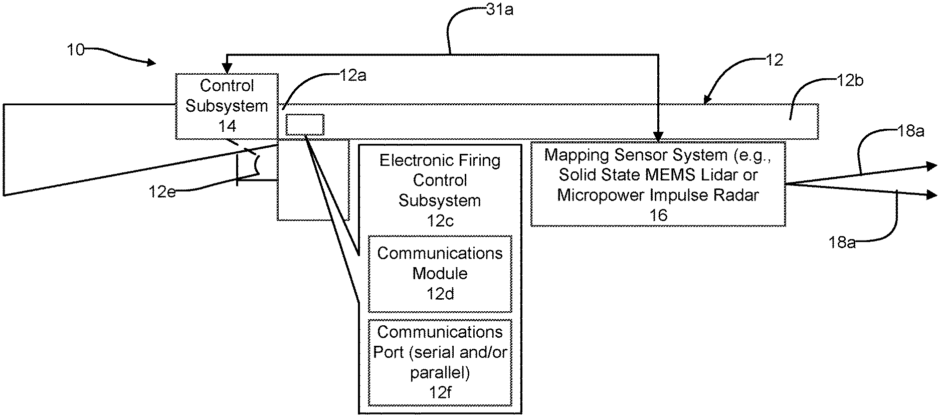
[0018] FIG. 1 is a high level block diagram of one embodiment of a system in accordance with the present disclosure being employed on a kinetic weapon such as a fully automatic or semiautomatic, small arms caliber rifle;
[0019] FIG. 2 is a high level block diagram illustration of the various components that the system may incorporate; and
[0020] FIG. 3 is a flowchart of operations that may be performed by the system of FIG. 1 in identifying and acquiring a target, aiming and controlling firing of the kinetic weapon shown in FIG. 1.
DETAILED DESCRIPTION
[0021] Example embodiments will now be described more fully with reference to the accompanying drawings.
[0022] Referring to FIG. 1, a target acquisition, aiming and fire control system 10 is shown in accordance with one embodiment of the present disclosure. For convenience the target acquisition, aiming and fire control system 10 will be referred to throughout the following discussion as simply "the system 10".
[0023] The system 10 in this example may be used with a kinetic weapon 12, which in this example is shown as a small arms caliber automatic or semiautomatic rifle. However, it will be appreciated that the system 10 may be employed on other types of kinetic weapons and is not limited to use with only rifles, or with a kinetic weapon of any specific caliber. Accordingly, the system 10 may be implemented with handguns, shoulder fired weapons (e.g., rocket propelled grenade launchers, etc.), mortar tubes, and even with mobile weapon systems (e.g., on tanks, howitzers, artillery). The system 10 may also potentially be employed with airborne platforms such as aircraft, rotorcraft, drones, as well as on marine vessels. The system 10 may be used in any application where accurate target acquisition and aiming and fire control of a projectile from medium to long range (e.g., typically 10 m or longer) is needed. It is possible to use the system 10 for short range operation, however the need for precise alignment tends to drop at close ranges.
[0024] The system 10 may include a control subsystem 14 and an environmental mapping sensor subsystem 16 in bi-directional communication with one another mounted on the weapon 12. In this example the control subsystem 14 is mounted on a receiver portion 12a of the weapon for easy access by the user, while the mapping sensor subsystem 16 is mounted from a barrel 12a of the weapon. However, the precise placement of these components may be varied from these locations; it is only necessary that the mapping sensor subsystem 16 have an unobstructed view (i.e., unobstructed by any portion of the weapons 12) and that the control subsystem 14 be conveniently accessible to the user. The specific type of weapon may with which the system 10 may dictate at least in part the preferred mounting locations for these components.
[0025] The system 10 may also include an electronic firing control subsystem 12c that is incorporated into or on the weapon 12. The electronic firing control subsystem 12c is able to electronically communicate, wirelessly or in wired fashion, with the control subsystem 14, and enables the subsystem 14 to fire the weapon (e.g., cause an appropriate signal to be applied to the firing pin or other firing mechanism of the weapon 12) at a precise time controlled by the subsystem 14. In this regard the electronic firing control subsystem 12c may include a wireless radio 12d or suitable communications port for enabling a wired connection with the control subsystem 14. If a wired connection is used, then the electronic firing control subsystem 12c may include a communications port 12f (serial and/or parallel) to enable the wired connection to be made with the control subsystem 14 via a suitable cable 31a. A wired connection may be preferable in that it would not create a detectable electromagnetic signature on a battlefield. The control subsystem 14 may also include one or more subsystems that are operably associated with a trigger 12e of the weapon 12, as will be explained more fully in the following paragraphs.
[0026] Referring to FIG. 2, the various components and subsystems of the system 10 are shown in greater in detail. The environmental mapping sensor subsystem 16 forms a controllably scanned electromagnetic wave energy propagation subsystem which projects controllably scanned electromagnetic wave energy at a desired scene where one or more targets may be present. The environmental mapping sensor subsystem 16 (hereinafter simply the "mapping sensor subsystem" 16) may incorporate, in one embodiment, a solid state MEMS (micro-electro-mechanical system) Lidar unit. For convenience, this component will be referred to simply as "Lidar unit" 18 throughout the following discussion. Optionally, though, or even in addition to a solid state MEMS Lidar unit, the environmental mapping sensor subsystem 16 could instead incorporate a micropower impulse radar. Both implementations are contemplated by the present disclosure. For convenience, however, the following discussion will involve using the Lidar unit 18 as the electromagnetic wave energy scanning component.
[0027] The Lidar unit 18 generates and scans one or more beams 18a to image a scene in which one or more potential targets may be present. The beams 18a may be used to not only identify valid targets within the scene but also to assist the user of the weapon 12 in aiming the weapon at the valid target, or further even to help control firing of the weapon at the precise instant where the weapon is aimed at the valid target. Optionally, a visible laser 20 may be included with a separate On/Off switch 22 that may be engaged by the user. The visible laser 20 may generate a visible laser beam 20a to identify to the user a specific target or specific location on a given target during an aiming process, which will be described further in the following paragraphs.
[0028] The control subsystem 14 may include a collection of environmental sensors 24 (e.g., humidity, wind velocity, barometric pressure, altitude, weapon barrel temperature sensor, etc.) which provide various types of information that is helpful or necessary for accurate target acquisition and aiming of the weapon 12. A database 26 may be provided for holding various data pertaining to the weapon and or the specific projectile being fired (e.g., projectile caliber, bullet weight, bullet velocity, bullet material/construction, barrel length, explosive powder quantity, etc.). A plurality of weapon motion sensors 28 may be provided which include one of accelerometers for sensing real time roll, pitch, yaw, etc. of the weapon 12 and providing real time electrical signals in accordance therewith. An optional wireless radio (e.g., BLUETOOTH.RTM. communications protocol module) 30 may be included to wirelessly communicate with the electronic firing control subsystem 12c. Alternatively, a communications port 31 (serial and/or parallel) may be provided to enable the wired connection (i.e., with cable 31a) described above. As noted above, the wired connection will likely be preferred in most instances, as this avoids generating an electromagnetic signature in the field that could give away the shooter's/user's location.
[0029] The control subsystem 14 may further include an environmental compensation software module 32 which makes use of the data collected by the environmental sensors 24 that helps the system 10 compensate for environment factors (e.g., wind direction and wind speed, altitude, etc.) that may have a bearing on the trajectory of the projectile being filed from the weapon.
[0030] A target/object recognition prioritization software module ("TORPS module") 34 may be included in the control subsystem 14 which helps to identify targets within a field of view of the Lidar unit 18, and optionally to prioritize targets. The TORPS module 34 may include a database 34a with 3D models of various objects including adult humans, child humans, various animals, various objects such as cars, trucks or other objects, which the system 10 is able to identify. Various objects within the database 34a may be classified as targets or non-targets, and objects designated as targets may optionally be provided with a priority categorization designating an importance of the object relative to other objects within the database. Although, as discussed further below, in most instances it is expected that the preferred prioritization will be based on the available valid targets that are closest to the user firing the weapon 12.
[0031] With further reference to FIG. 2, the control subsystem 14 includes an electronic controller 36 that may have a non-volatile memory (RAM or ROM), for controlling overall operation of the system 10. The electronic controller 36 may receive inputs from components or subsystems 24, 32, 26, 28, 32 and 34, in addition to a fire command detection sensor 38, and a kick actuator subsystem 40. An On/Off switch 42 may be provided that controls the application of power (e.g., DC or AC power) from a power source 44 (e.g., on-board DC battery) to the various system 10 components and subsystems. An optional display 46 (e.g., LCD, LED, OLED, etc.) may be included for providing the user of the weapon 12 a display of the scene being imaged by the system 10.
[0032] The kick actuator subsystem 40 may be component that initiates movement of one or more masses (e.g., 1 lb weight(s)) to provide a small, momentary movement to the weapon, to help aim the barrel 12b. One or more actuators, for example electrically controlled linear actuators, may be used to move one or more the weight in one the X, Y or Z axes as needed. The electronic controller 36 may use information from one or more of the components and subsystems 24, 26, 28, 32 and 34 in determining what control signals need to be applied to the kick actuator subsystem 40, and at exactly the precise time, to achieve the needed degree of overlap with the Lidar unit 18a to accurately aim the weapon 12 at a determined target. This active type control may enable the system 10 to reach convergence (i.e., desired degree of overlap) with a selected target faster than waiting on the user driven drift of the weapon 12, while the user is aiming the weapon, to reach the desired point of convergence. In the active mode of operation, the kick actuator subsystem 40 is able to help bring the weapon 12 rapidly into alignment, thus eliminating firing delays possibly caused by gusting winds or other factors which affect the user while holding the weapon 12.
[0033] Both of the control subsystem 14 and the Lidar weapon 12 preferably form a significantly more compact package than present day aiming systems typically used with kinetic weapons. The present system 10 thus provides a lightweight system and is adaptable to more weapons and a wider variety of packages than present day targeting systems. The operation of the system 10 provides the advantage that the system is not susceptible to being compromised by shining a laser at it, while the Lidar unit 18 performance likewise will not be degraded by such an external light source. The Lidar unit 18 is also significantly less sensitive to interference or environmental illumination, meaning it may be expected to provide significantly increased reliability over other present day targeting systems.
[0034] In operation the Lidar unit 18 operates as an environmental mapping sensor with a relatively small field. As noted above, the Lidar unit 18 may instead comprise a micropower impulse radar unit, and both implementations are envisioned by the present disclosure. However, a micropower impulse radar unit would be able to penetrate wooden walls and other structures that may prove an impediment to the Lidar unit 18 beam 18a.
[0035] This Lidar unit 18 is attached to the weapon 12, in the example of FIG. 1 to the barrel 12b, and is attached so that it points largely along the bore of the barrel 12b. The Lidar unit 18 preferably uses a solid state MEMS Lidar. The benefit this provides is small size, weight and power demand, while providing high precision and high speed scanning of a scene. The Lidar unit 18 may be configured to scan with multiple different wavelengths to ensure measurement capability in a wide variety of environments, even seeing through vegetation or plastic sheeting. It will be appreciated that this feature provides a significant benefit when using the system 10 in forested environments. The environmental mapping sensor subsystem 16 only requires a relatively small field of view, for example around a few degrees off bore of the weapon 12. For long range use (e.g., possibly longer than 100 meters), the beam steering capability and aperture of the Lidar unit 18 could be tuned to provide approximately a 100 urad beam divergence, to provide centimeter scale beam alignment at around 200 m or at even longer distances. The Lidar unit 18 generates a 3D point cloud map of the view downstream of the weapon 12, with fine resolution suitable to discern the shape of objects at distances of upwards of 200 m or possibly even greater. Shorter range versions of the system 10, which may be of interest to law enforcement agencies, may include a mapping sensor subsystem 16 which is tuned for closer range operation with a wider field of view (FOV) and reduced range. It is expected that precision targeting would only be of general value at ranges greater than at least about 10 meters; at closer ranges, the user is likely able to target the projectile from the weapon 12 as desired.
[0036] The Lidar unit 18 scan need not be a set raster operation. The mapping sensor subsystem 16 may initially carry out a low resolution mapping of its full FOV, then focus in on any return signals, collecting a fine point cloud around those regions of interest in an adaptive manner. This would ensure the maximum utility of the collected data with the lowest data bandwidth, unlike a camera.
[0037] The Lidar unit 18 may also use its laser to map the wind velocity along the potential path of the projectile, using standard Doppler techniques or other mapping techniques. In one instance, this may require scanning the beam 18a around in a pattern of a cone to collect a set of velocity measurements, from which the wind vector may be discerned.
[0038] All of these pieces of information (environmental and movement of the weapon 12) may be used by the electronic controller 36 in the precision targeting system to predict the impact location of the projectile to be fired from the weapon 12. The impact location would generally be within the FOV of the mapping sensor subsystem 16. In the case that sensor is the Lidar unit 18, the visible laser beam 20a may be placed in parallel to the scanning laser of the Lidar unit. The visible laser 20 may be controlled by the mapping sensor subsystem 16 (and/or electronic controller 36) so that the visible laser occasionally generates a pulse out to mark the spot of the expected impact downstream. This would provide the user the ability to see where they would hit without needing a scope, which is a critical difference from conventional targeting cameras, and a virtual necessity for dynamic conditions.
[0039] The active beam steering provided by the mapping sensor subsystem 16 and the Lidar unit 18 may also be used to "paint" more than a point on an identified target. For instance, a circle could be drawn to indicate the region of confidence for impact of the projectile. The combined designation and area scanning is possible with the high speed beam steering capability of the mapping sensor subsystem 16 and the Lidar unit 18.
[0040] Calibration of the system 10 may be carried out by firing at least one round of ammunition against a surface within range of the Lidar unit 18. The mapping sensor subsystem 16 may use the Lidar unit 18 to scan the surface, identify the impact point and update the internal predictions of barrel 12b angle to match the measured impact location. This would likely require that the Lidar unit 18 be able to discern the impact location, which would mean the spot left by the impact of the projectile must be large enough to discern during scanning. This would certainly be possible if impacts occur well within the full range of measurement. Data from multiple shots could be used by the electronic controller 36 to develop impact statistics, for instance an average location and circle of probability. The predictions could be slowly updated in real time with each shot, so if the impact location starts to drift from predictions then the alignment values could be updated by the electronic controller 36. This would allow the system 10 to auto calibrate itself, and remove barrel 12b heating or warping issues from consideration.
[0041] The system 10 would not need to be interfaced to a conventional scope; rather the entirety of the system 10 may be placed in a housing which can be readily attached to the weapon 12 in a manner which does not obstruct ordinary use of the weapon 12 or its operation. The system 10 interfaces with the weapon 12 and provide an additional sensor (e.g., fire command detection sensor 38, for determining when the user has indicated that the weapon can now be fired. One specific mode of operation is to provide the fire command detection sensor 38 as a switch or component (e.g., button) that the user may press and hold when the precision targeting operation is desired. Alternatively the fire command detection sensor 38 may be placed adjacent the trigger 12e and may sense when the trigger 12e has been moved a small, predetermined distance by the user. So in this mode, the user is able to pull the trigger 12e of the weapon in the normal manner, and this movement will be detected as a fire command signal. The mapping sensor subsystem 16 uses the Lidar unit 18 to scan the down-bore field, to confirm alignment with at least one identified target, and the electronic controller 36 generates an internal "fire" command that is communicated to the electronic firing control subsystem 12c on the weapon 12 when the predicted impact location matches the observed target location, allowing the weapon to fire.
[0042] One more general mode of operation for the system 10 may be to simply provide a real-time calibrated prediction of impact location via a designation using the visible laser beam 20a. This would not impair the user's ability to fire the weapon 12 in its ordinary manner. It would also not require the user to be looking through any type of sight, meaning that the user is still able to view areas around a scene at which the weapon 12 is being aimed, and therefore is more aware of dynamic conditions in the general vicinity. Conventional camera tracking techniques with present day targeting systems are not able to provide this benefit.
[0043] A second general mode of operation for the system 10 is to aid in the targeting by actively identifying objects downstream, with the system 10 choosing specific locations on these objects and deferring the user fire command (provided by pulling the trigger 12e) until the predicted impact location sufficiently overlaps with the target location(s). This second mode critically differs from conventional targeting cameras in several ways. First, it does not require the user to tag the target, rather the environmental mapping sensor subsystem 16 does so automatically without the need for the user to be peering down a scope mounted on the weapon 12. Second, the mapping sensor subsystem 16 is illumination insensitive, so it works equally well in daytime or nighttime conditions. Third, the mapping sensor subsystem 16 may be configured to use specially selected wavelengths which enable penetrating intervening material such as vegetation or water, which would otherwise obstruct the view of conventional targeting systems. Moreover, the first and second general modes described above are not exclusive, the user could keep on the laser designation provided by the visible laser beam 20a and still select precision targeting by engaging the fire command detection sensor 38.
[0044] In one of its "active" modes of operation, the system 10 may scan the downstream scene, identify one or more objects in the scene as potential targets, and then tag or select one or more specific target locations on specific targets based on the selected system mode. These operations may all be subsets of the second general mode identified above. These modes essentially configure the electronic controller 36 on how to choose target points on the object. The object identified to be closest to the bore of the weapon 12 (so in the user's sights) may in general be determined to be the most preferred available target. This may be the preferred method for hitting certain types of targets, for example airborne drones.
[0045] The environmental mapping sensor subsystem 16 may pass the point cloud data to the TORPS module 34, which may make use of one or more image recognition algorithms, when the user pulls the trigger 12e of the weapon 12. The modes below are examples of how the system 10 may identify the specific target areas from this data. Once these areas are chosen, the system 10 may then generate a fire control signal to the electronic firing control subsystem 12c of the weapon 12 only once the motion of the weapon aligns it so that the predicted impact location sufficiently overlaps (e.g., >90% hit probability) with the chosen target area. The target areas may be illuminated by some part of the visible laser beam 20a to show the user what the system 10 has identified as the target. This would enable the user to change the aim of the weapon 12 to ensure a hit.
[0046] Still another optional mode of operation is for the system 10 to target only typically non-lethal impacts on an individual (e.g., an arm, shoulder, etc. In this mode, the TORPS module 34 would use one or more suitable algorithms to identify non-lethal impact areas as the target is stationary or moving. This would reduce the chance of killing a human target, as the weapon would avoid hitting lethal areas of the individual. This non-lethal mode of operation may be of particular interest to law enforcement agencies, where a situation exists in which a threat to law enforcement personnel or bystanders needs to be eliminated, but where law enforcement personnel determine that non-lethal force on a human target may be sufficient to remove the threat without resorting to using lethal force.
[0047] Another optional mode of operation is the inverse of the nonlethal mode, that being using the TORPS module 34 with suitable algorithms to target only areas of a human target that would produce a lethal strike (e.g., head, center chest, abdomen, inner thigh, etc.). Still another optional mode of operation may be to configure the TORPS module 34 with suitable algorithms to target areas of conventional weakness in body armor, or possibly areas of known armor weakness of other objects such as troop carrying vehicles, tanks, etc., or areas of objects which, if hit, are virtually certain to immediately disable the object (e.g., engine, fuel tank, rotor structure, etc.). The foregoing are only a limited number of the possible operational modes that may be implemented using the system 10, and the system 10 will be understood as not being limited to any one or more specific operational modes.
[0048] Optionally, information provided by the system 10 (e.g., by the environmental sensors 24, and/or the environmental compensation mapping software module 32 and/or the TORPS module 34) could be fed back to a heads up display (HUD) being worn by the user, if desired, to provide imagery for around a corner, for instance, where the user of the weapon 12 would ordinarily not be able to visualize.
[0049] In certain use scenarios, the TORPS module 34 may be able to identify objects behind thin screens like vegetation. One mode for this is to have the visible laser 20a draw both the probable impact circle on the vegetation for the weapon user, as well as (or alternately with) the outline of any objects of interest observed behind the vegetation. This would provide the user with immediate feedback about the sensor readings and the targets selected within the FOV of the system 10.
[0050] The system 10 enables several different control schemes for discharging the weapon 12. First, the user switch 22 allows the active visible laser 20 to be turned on and off, by itself if desired by the user. The On/Off switch 42 enables the control subsystem 14 and the Lidar unit 18 to be turned on. Second, the user switch 22 may be turned on by the user to initiate active sensing with the system 10 using the Lidar unit 18. Third, the fire command detection sensor 38 may be arranged parallel to the weapon trigger 12e to sense when the user is applying pressure to the trigger, or alternatively to sense when the trigger moves a short predetermined distance (typically called the "takeup" distance), and would delay firing when the desired pressure applied to, or movement of, the trigger is reached, and until the required degree of target overlap occurs with an acquired target. Optionally, another mode of operation, for example sensing a second trigger 12e pull by the user within a short predetermined time period (e.g., 2-5 seconds), may cause the electronic controller 36 to cancel a previously detected fire signal from the user, and place the system 10 in a standby mode.
[0051] Referring to FIG. 3, a high level flowchart 100 is illustrated to show various operations that may be implemented using the system 10. At operation 102 the system 10 may collect real time environmental data using the environmental sensors 24. At operation 104 the system 10 may use the mapping sensor subsystem 16 to identify targets in the FOV. At operation 106 the system 10 may also obtain weapon/projectile data and previously recorded/stored calibration and alignment data. The electronic controller 36 may be used to control and/or carry out one or more of operations 102, 104 and 106.
[0052] At operation 108 the mapping sensor subsystem 16 identifies one or more specific objects in the FOV as valid targets. At operation 110 the TORPS module 34 may automatically select one of a plurality of identified, valid targets, for example the closest one to the user, which are within the FOV. At operation 112 the TORPS module 34 and the electronic controller 36 may be used to make an initial estimate of the real time predicted impact location on the selected target. The present degree of overlap of the point of impact, as well as its impact statistics (such as probable impact outline to show region of high impact likelihood) with the selected target may be presented on the display 46, as indicated at optional operation 116a. Information may also be displayed downstream, as indicated at optional operation 116b, by the mapping sensor subsystem 16 using an illumination (e.g., beam 20a in FIG. 2) visible to the user, and drawing out the information so that the user does need to look at a display or scope. This information could include a point illuminating the presently determined impact location, a probable impact outline to show region of high impact likelihood, and an outline or other similar highlighting of the automatically identified target. Such identification would allow the user to confirm the weapon 12 is locking onto the selected (i.e., valid) target, and determine what orientation correction is required to ensure impact on the target.
[0053] At operation 114 the control system 14 makes a determination if a "weapon fire" command has been received from the user. If the answer to this inquiry is "No", then operation 112 may be repeated. If the answer is "Yes", then at operation 118, a check is then made if the predicted impact location overlaps at least a predetermined minimum degree with the selected target. If this check produces a "No" answer, then the kick actuator subsystem 40 may be used at operation 120 (which is optional, however) in an effort to achieve the minimum predetermined degree of overlap between the projected point of impact and the selected target. The weapon 12 movement (i.e., "kick") provided by the kick actuator subsystem 40 at operation 120 will change the impact location, so the system 10 will return to operation 112 to update estimated impact location. If the check at operation 118 indicates that the predetermined minimum degree of overlap is present, then at operation 122 the control subsystem 14 transmits a firing signal to the electronic firing control subsystem 12c on the weapon 12 to fire the weapon, or otherwise allows the weapon to fire (for example, allowing the trigger 12e to be fully depressed by the user).
[0054] Further to the above operations, other firing sequences may be carried out by the system 10 as follows. The user has the active visible laser 20 turned on with the laser beam 20a being projected on the approximate location of projectile impact. The user aims the weapon 12 at the target general area, assisted by the laser beam 20a acting as an impact location designator, and engages the active targeting mode by switching on the On/Off switch 42, and then pulls the trigger 12e to signal the system 10 initiate firing of the weapon 12.
[0055] When the On/Off switch 42 is turned on, thus powering on the targeting system 10, in real time the TORPS module 34 initiates the active targeting mode and identifies a plurality of valid targets, and further designates one of the valid targets as being the one closest to the calculated projectile trajectory and calculated impact location. When the user begins to pull the trigger 12e, the active mode of the system 10, implemented using the TORPS module 34, waits until the weapon 12 aligns to these areas. The weapon trigger 12e is only allowed to be fully depressed, or recognized as being fully depressed, once the weapon is in alignment to hit the target area. Optionally, movement of the trigger 12e may be physically obstructed by the system 10, for example through a movable element positioned behind the trigger 12e, to accomplish this. The movable element may be moved by the system 10 only when the weapon 12 is properly aimed at the identified target.
[0056] In the active mode, the kick actuator subsystem 40 may be immediately driven to shift the weapon 12 slightly into alignment. If the desired mode is chosen, the target areas may be illuminated by the laser 20 to show the user what the system 10 has identified as the target. Optionally, the visible laser 20 may be activated by the user switch 22 being activated by pressure on the trigger 12e. The benefit of using the trigger 12e to activate this is that the target illumination would be brief and only during the specific moment of alignment. In the case that the weapon 12 is misaligned, the laser beam 20a will provide a visual cue for the user to manually fix alignment. Once the weapon 12 is in alignment, the trigger 12e may be allowed to physically move, or optionally its movement may be recognized, thus letting the user's triggering pulling action fire the weapon 12.
[0057] The system 10 may also be incorporated for use on weapons such as tasers. The system 10 may be used to ensure that both of the taser electrodes fired from the taser impact the target at a preferred location on the target.
[0058] The foregoing description of the embodiments has been provided for purposes of illustration and description. It is not intended to be exhaustive or to limit the disclosure. Individual elements or features of a particular embodiment are generally not limited to that particular embodiment, but, where applicable, are interchangeable and can be used in a selected embodiment, even if not specifically shown or described. The same may also be varied in many ways. Such variations are not to be regarded as a departure from the disclosure, and all such modifications are intended to be included within the scope of the disclosure.
[0059] Example embodiments are provided so that this disclosure will be thorough, and will fully convey the scope to those who are skilled in the art. Numerous specific details are set forth such as examples of specific components, devices, and methods, to provide a thorough understanding of embodiments of the present disclosure. It will be apparent to those skilled in the art that specific details need not be employed, that example embodiments may be embodied in many different forms and that neither should be construed to limit the scope of the disclosure. In some example embodiments, well-known processes, well-known device structures, and well-known technologies are not described in detail.
[0060] The terminology used herein is for the purpose of describing particular example embodiments only and is not intended to be limiting. As used herein, the singular forms "a," "an," and "the" may be intended to include the plural forms as well, unless the context clearly indicates otherwise. The terms "comprises," "comprising," "including," and "having," are inclusive and therefore specify the presence of stated features, integers, steps, operations, elements, and/or components, but do not preclude the presence or addition of one or more other features, integers, steps, operations, elements, components, and/or groups thereof. The method steps, processes, and operations described herein are not to be construed as necessarily requiring their performance in the particular order discussed or illustrated, unless specifically identified as an order of performance. It is also to be understood that additional or alternative steps may be employed.
[0061] When an element or layer is referred to as being "on," "engaged to," "connected to," or "coupled to" another element or layer, it may be directly on, engaged, connected or coupled to the other element or layer, or intervening elements or layers may be present. In contrast, when an element is referred to as being "directly on," "directly engaged to," "directly connected to," or "directly coupled to" another element or layer, there may be no intervening elements or layers present. Other words used to describe the relationship between elements should be interpreted in a like fashion (e.g., "between" versus "directly between," "adjacent" versus "directly adjacent," etc.). As used herein, the term "and/or" includes any and all combinations of one or more of the associated listed items.
[0062] Although the terms first, second, third, etc. may be used herein to describe various elements, components, regions, layers and/or sections, these elements, components, regions, layers and/or sections should not be limited by these terms. These terms may be only used to distinguish one element, component, region, layer or section from another region, layer or section. Terms such as "first," "second," and other numerical terms when used herein do not imply a sequence or order unless clearly indicated by the context. Thus, a first element, component, region, layer or section discussed below could be termed a second element, component, region, layer or section without departing from the teachings of the example embodiments.
[0063] Spatially relative terms, such as "inner," "outer," "beneath," "below," "lower," "above," "upper," and the like, may be used herein for ease of description to describe one element or feature's relationship to another element(s) or feature(s) as illustrated in the figures. Spatially relative terms may be intended to encompass different orientations of the device in use or operation in addition to the orientation depicted in the figures. For example, if the device in the figures is turned over, elements described as "below" or "beneath" other elements or features would then be oriented "above" the other elements or features. Thus, the example term "below" can encompass both an orientation of above and below. The device may be otherwise oriented (rotated 90 degrees or at other orientations) and the spatially relative descriptors used herein interpreted accordingly.
* * * * *
D00000
D00001
D00002
D00003
XML
uspto.report is an independent third-party trademark research tool that is not affiliated, endorsed, or sponsored by the United States Patent and Trademark Office (USPTO) or any other governmental organization. The information provided by uspto.report is based on publicly available data at the time of writing and is intended for informational purposes only.
While we strive to provide accurate and up-to-date information, we do not guarantee the accuracy, completeness, reliability, or suitability of the information displayed on this site. The use of this site is at your own risk. Any reliance you place on such information is therefore strictly at your own risk.
All official trademark data, including owner information, should be verified by visiting the official USPTO website at www.uspto.gov. This site is not intended to replace professional legal advice and should not be used as a substitute for consulting with a legal professional who is knowledgeable about trademark law.