Ice Maker With Specifically Positioned Drive Unit, Household Refrigeration Apparatus And Method For Assembling An Ice Maker
HOSAMANI; PRASHANTAGOUDA ; et al.
U.S. patent application number 16/203026 was filed with the patent office on 2020-05-28 for ice maker with specifically positioned drive unit, household refrigeration apparatus and method for assembling an ice maker. The applicant listed for this patent is BSH HAUSGERAETE GMBH. Invention is credited to PRASHANTAGOUDA HOSAMANI, JORGE CARLOS MONTALVO SANCHEZ, MATHIAS SIGL, ROBERT STAHL.
| Application Number | 20200166264 16/203026 |
| Document ID | / |
| Family ID | 70546096 |
| Filed Date | 2020-05-28 |


View All Diagrams
| United States Patent Application | 20200166264 |
| Kind Code | A1 |
| HOSAMANI; PRASHANTAGOUDA ; et al. | May 28, 2020 |
ICE MAKER WITH SPECIFICALLY POSITIONED DRIVE UNIT, HOUSEHOLD REFRIGERATION APPARATUS AND METHOD FOR ASSEMBLING AN ICE MAKER
Abstract
An ice maker for a household refrigeration apparatus has a housing with an opening, through which ice is transportable from an interior of the housing out of the housing, a flap, which is movably arranged in the housing and adjustable for closing or opening the opening, and a drive unit, which is coupled to the flap by a coupling device of the ice maker, to move the flap. The drive unit is formed as a separate module and the entire module of the drive unit is arranged adjacent to the opening in the housing.
| Inventors: | HOSAMANI; PRASHANTAGOUDA; (ULM, DE) ; STAHL; ROBERT; (HERBRECHTINGEN, DE) ; SIGL; MATHIAS; (HERBRECHTINGEN, DE) ; MONTALVO SANCHEZ; JORGE CARLOS; (KNOXVILLE, TN) | ||||||||||
| Applicant: |
|
||||||||||
|---|---|---|---|---|---|---|---|---|---|---|---|
| Family ID: | 70546096 | ||||||||||
| Appl. No.: | 16/203026 | ||||||||||
| Filed: | November 28, 2018 |
| Current U.S. Class: | 1/1 |
| Current CPC Class: | F25C 2400/10 20130101; F25C 2500/02 20130101; F25C 1/24 20130101; F25C 5/24 20180101; F25C 5/22 20180101 |
| International Class: | F25C 5/20 20060101 F25C005/20; F25C 1/24 20060101 F25C001/24 |
Claims
1. An ice maker for a household refrigeration apparatus, comprising a housing with an opening, through which ice is transportable from an interior of the housing out of the housing; a flap, which is movably arranged in the housing and is adjustable for closing or opening the opening; a drive unit, which is coupled to the flap by a coupling device of the ice maker, to move the flap, wherein the drive unit is formed as a separate module and an entirety of said module of the drive unit is arranged adjacent to the opening in the housing.
2. The ice maker according to claim 1, wherein the housing has a depth direction, and the opening is arranged in a front third of depth of the entire depth of the housing and the module of the drive unit is arranged in this front third of depth.
3. The ice maker according to claim 2, wherein the housing has a depth direction, and the housing comprises a front flange, wherein the module is arranged adjacent to the front flange.
4. The ice maker according to claim 1, wherein the housing has a depth direction, and with front-side view of the ice maker in this depth direction, the module is arranged in a front-side corner area of the interior of the housing.
5. The ice maker according to claim 4, wherein the module is arranged in a left lower, front-side corner area of the interior.
6. The ice maker according to claim 1, comprising a collecting pan for ice form elements, wherein the collecting pan is arranged in the housing and the module of the drive unit is arranged laterally directly next to the collecting pan.
7. The ice maker according to claim 1, wherein the coupling device comprises a coupling rod, which is connected to the flap and the module of the drive unit.
8. The ice maker according to claim 7, wherein the flap comprises an engagement slit at an end, with which the coupling rod engages.
9. The ice maker according to claim 1, wherein the flap is formed shovel-like and curved.
10. The ice maker according to claim 1, wherein the module of the drive unit comprises a module housing, which is non-destructively detachably arranged at the housing.
11. The ice maker according to claim 10, wherein the module housing is fixed to the housing by a mechanical connection, which is a plug connection or a locking connection or a plug and locking connection.
12. The ice maker according to claim 11, wherein the mechanical connection comprises at least one plug runner and one plug rail, which can be plugged together by a linear relative movement to each other.
13. The ice maker according to claim 12, wherein the plug runner is formed integrally with the module housing, and the plug rail is formed integrally with the housing.
14. The ice maker according to claim 1, wherein the drive unit comprises a motor and an actuating element, which is coupled to the motor, wherein the actuating element is coupled to the flap.
15. A household refrigeration apparatus, comprising an apparatus housing formed with a receiving space for food, and an ice maker having: a housing with an opening, through which ice is transportable from an interior of the housing out of the housing, a flap, which is movably arranged in the housing and adjustable for closing or opening the opening, a drive unit, which is coupled to the flap by a coupling device of the ice maker, to move the flap, wherein said drive unit is formed as a separate module, and an entire said module of the drive unit is arranged adjacent to the opening in the housing.
16. A method for assembling an ice maker for a household refrigeration apparatus, comprising the following steps: providing at least a partial area of a housing of the ice maker; providing a drive unit of the ice maker as an own, separate module, wherein the drive unit is formed for moving a flap of the ice maker, wherein the flap is formed for opening and closing an opening, through which ice is transportable from an interior of the housing out of the housing, wherein the module comprises plug elements and the housing comprises mating plug elements, and the plug elements are coupled to the mating plug elements to a mechanical connection, such that the module is displaced linearly relative to the housing in defined manner by the relative movement between the plug elements and the mating plug elements in further assembly of the module with the housing until the assembled final position of the module at the housing is achieved.
Description
TECHNICAL FIELD
[0001] An aspect of the invention relates to a household refrigeration apparatus comprising an ice maker comprising a specifically constructed housing. A further aspect of the invention relates to a method for assembling a housing of an ice maker.
BACKGROUND OF THE INVENTION
[0002] Household refrigeration apparatuses are known in diverse configurations. In this context, it is also known that an interior container bounds a receiving space for a household refrigeration apparatus. This receiving space is usually a refrigerating compartment. A partial area is occupied by an ice maker in this receiving space. Thereto, it is known that the ice maker is separated from the remaining volume of the refrigerating compartment. In this context, it is provided that a housing area of the housing of the ice maker is formed by a separate wall element, which is attached to inner sides of walls of the interior container in the interior of the receiving space of the interior container.
[0003] From U.S. Pat. No. 6,880,355 B2, a household refrigeration apparatus with an ice maker is known. The ice maker occupies a partial area of the interior volume of a refrigerating compartment, which is a receiving space for food. The ice maker comprises a housing. A drive unit is arranged in this housing, by which a control means is to be actuated. An outlet of the housing is closed or opened by the control means. Ice can be output from the ice maker via this outlet. In the configuration of the ice maker, it is provided that this drive unit is arranged at the rearmost end of the housing viewed in depth direction of the household refrigeration apparatus. However, the control means is arranged at the frontmost end, where the opening is also formed. Thereby, it is required in this configuration to bridge a relatively long path, namely the entire length of this housing of the ice maker measured in depth direction, to provide a mechanical coupling between the drive unit and this control means. In this respect, it is provided that a thin rod drive is formed, which extends over this entire distance. Thereto, this relatively thin and delicate rod is mechanically fixed or suspended at multiple locations. Due to the different positions of the components, it comprises multiply bent areas to be able to allow the mechanical coupling to the drive unit on the one and to the control means on the other hand anyway. Therefore, the coupling distance is formed by a very long element, namely this connecting rod. By such a configuration, however, disadvantages exist to the effect that more space is required, movement transmission from the drive unit to the control means is very inaccurately effected on the other hand. Here, tolerances are given by the large path distance, by which the precision of the movement transmission, which is generated by the drive unit, and is then performed by the control means, is restricted and deviating, respectively. This also results in the fact that the movement of the control means becomes inaccurate and an open position or a closed position of this control means is only achieved to a limited extent. Thereby, problems in passing the ice can occur on the one hand, on the other hand, if this control means is not completely opened, jam of ice in the opening not completely unblocked can occur. Moreover, a loss of stability is also associated with this very thin and delicate connecting rod. This means that the long rod can also deform in itself, for example bend or twist, upon force effect by the drive unit. Thereby too, an insufficient and not complete or not direct transmission of the movement initiated by the drive unit to this control means can be effected. In the configuration of the ice maker from the prior art, a very expensive assembly process is also required due to the plurality of components and the individual positions.
SUMMARY OF THE INVENTION
[0004] It is an object of the present invention to provide an ice maker, in which the movements initiated by a drive unit can be transmitted to a flap in improved manner such that opening and closing this flap are improved. Similarly, it is an object of the invention to provide a household refrigeration apparatus with such an ice maker.
[0005] Furthermore, it is the object to simplify the assembly of a drive unit in an ice maker.
[0006] This object is solved by an ice maker, a household refrigeration apparatus and a method according to the independent claims.
[0007] An aspect relates to an ice maker for a household refrigeration apparatus comprising a housing with an opening, through which ice is transportable from an interior of the housing out of the housing. The ice maker comprises a flap, which is movably arranged in the housing and is adjustable for closing or opening the opening. The ice maker comprises a drive unit, which is coupled to the flap by a coupling device of the ice maker to move the flap. The drive unit is formed as a separate module, wherein the entire module of the drive unit is arranged adjacent to the opening in the housing.
[0008] A further aspect relates to a household refrigeration apparatus comprising
[0009] an apparatus housing with a receiving space for food, and
[0010] an ice maker. The ice maker comprises a housing with an opening, through which ice is transportable from an interior of the housing out of the housing. It comprises a flap, which is movably arranged in the housing and adjustable for closing or opening the opening. The ice maker comprises a drive unit, which is coupled to the flap by a coupling device of the ice maker to move the flap. The drive unit is formed as a separate module, wherein the entire module of the drive unit is arranged adjacent to the opening in the housing.
[0011] A further aspect relates to a method for assembling an ice maker for a household refrigeration apparatus, comprising the following steps:
[0012] providing a housing of the ice maker;
[0013] providing a drive unit of the ice maker as an own, separate module, wherein the drive unit is formed for moving a flap of the ice maker, wherein the flap is formed for opening and closing an opening, through which ice is transportable from an interior of the housing out of the housing,
[0014] wherein the module comprises plug elements and the housing comprises mating plug elements, and the plug elements are coupled to the mating plug elements to a plug connection such that the module is displaced linearly relative to the housing in defined manner by the relative movement between the plug elements and the mating plug elements in the further assembly of the module with the housing until the assembled final position of the module is achieved.
[0015] Further features of the invention are apparent from the claims, the figures and the description of figures. The features and feature combinations mentioned above in the description as well as the features and feature combinations mentioned below in the description of figures and/or shown in the figures alone are usable not only in the respectively specified combination, but also in other combinations without departing from the scope of the invention. Thus, implementations are also to be considered as encompassed and disclosed by the invention, which are not explicitly shown in the figures and explained, but arise from and can be generated by separated feature combinations from the explained implementations. Implementations and feature combinations are also to be considered as disclosed, which thus do not comprise all of the features of an originally formulated independent claim. Moreover, implementations and feature combinations are to be considered as disclosed, in particular by the implementations set out above, which extend beyond or deviate from the feature combinations set out in the relations of the claims.
BRIEF DESCRIPTION OF THE DRAWINGS
[0016] Below, embodiments of the invention are explained in more detail based on schematic drawings. There is shown:
[0017] FIG. 1 a simplified perspective representation of an embodiment of a household refrigeration apparatus according to the invention;
[0018] FIG. 2 a perspective representation of an embodiment of an interior container of the household refrigeration apparatus;
[0019] FIG. 3 a perspective representation of partial components of a housing of an ice maker, as it can be installed in the household refrigeration apparatus according to FIG. 1;
[0020] FIG. 4 an enlarged partial representation of FIG. 3;
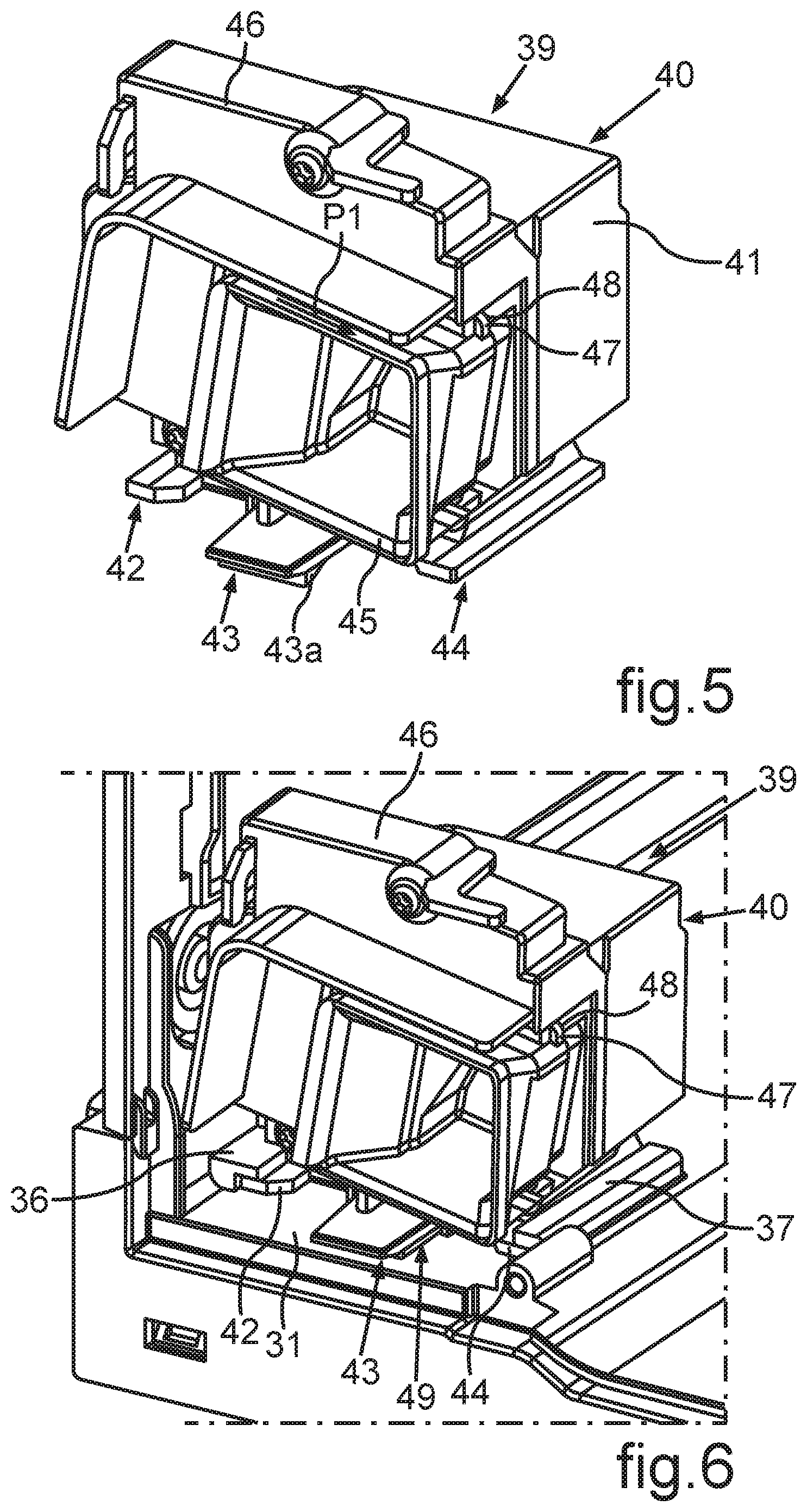
[0021] FIG. 5 a perspective representation of a drive unit of the ice maker;
[0022] FIG. 6 an assembled state of the drive unit according to FIG. 5 in a partial area of the housing according to FIG. 3 and FIG. 4;
[0023] FIG. 7 a sectional representation through a partial area of the configuration according to FIG. 6;
[0024] FIG. 8 a further sectional representation through the configuration according to FIG. 6 with additionally assembled front cover;
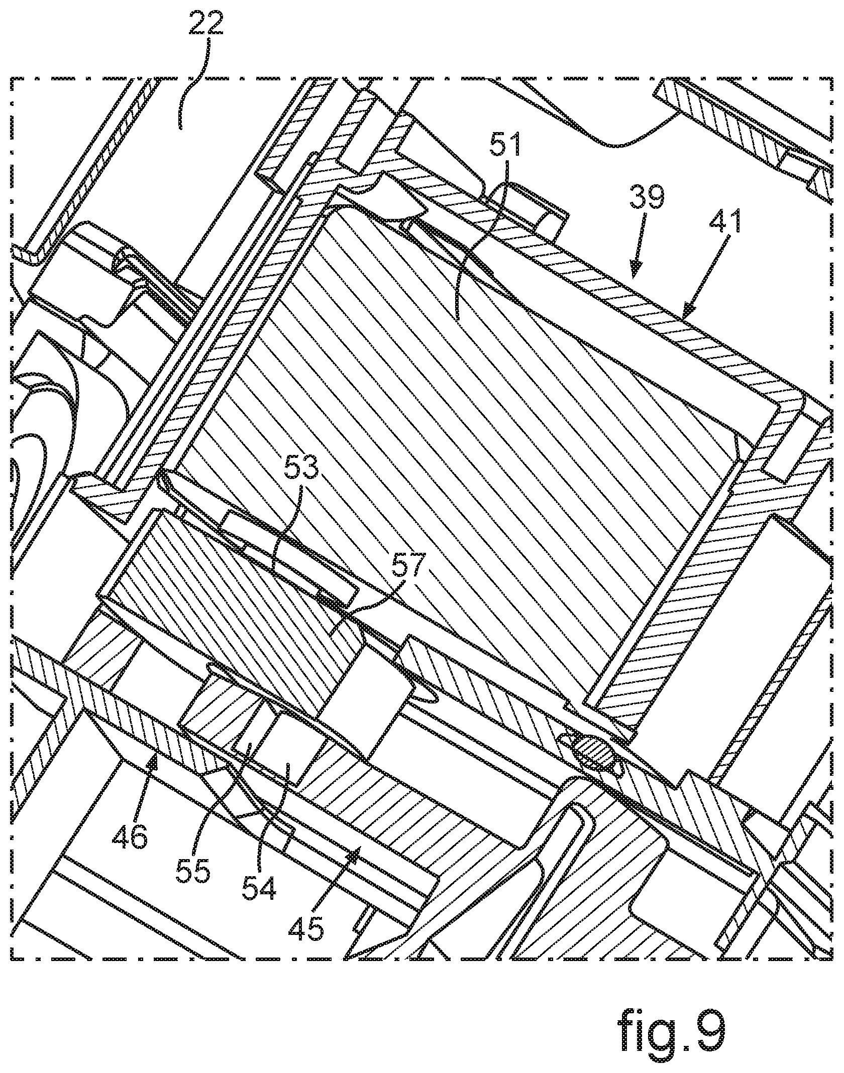
[0025] FIG. 9 a horizontal sectional representation through the assembled drive unit with the representation of specific partial components;
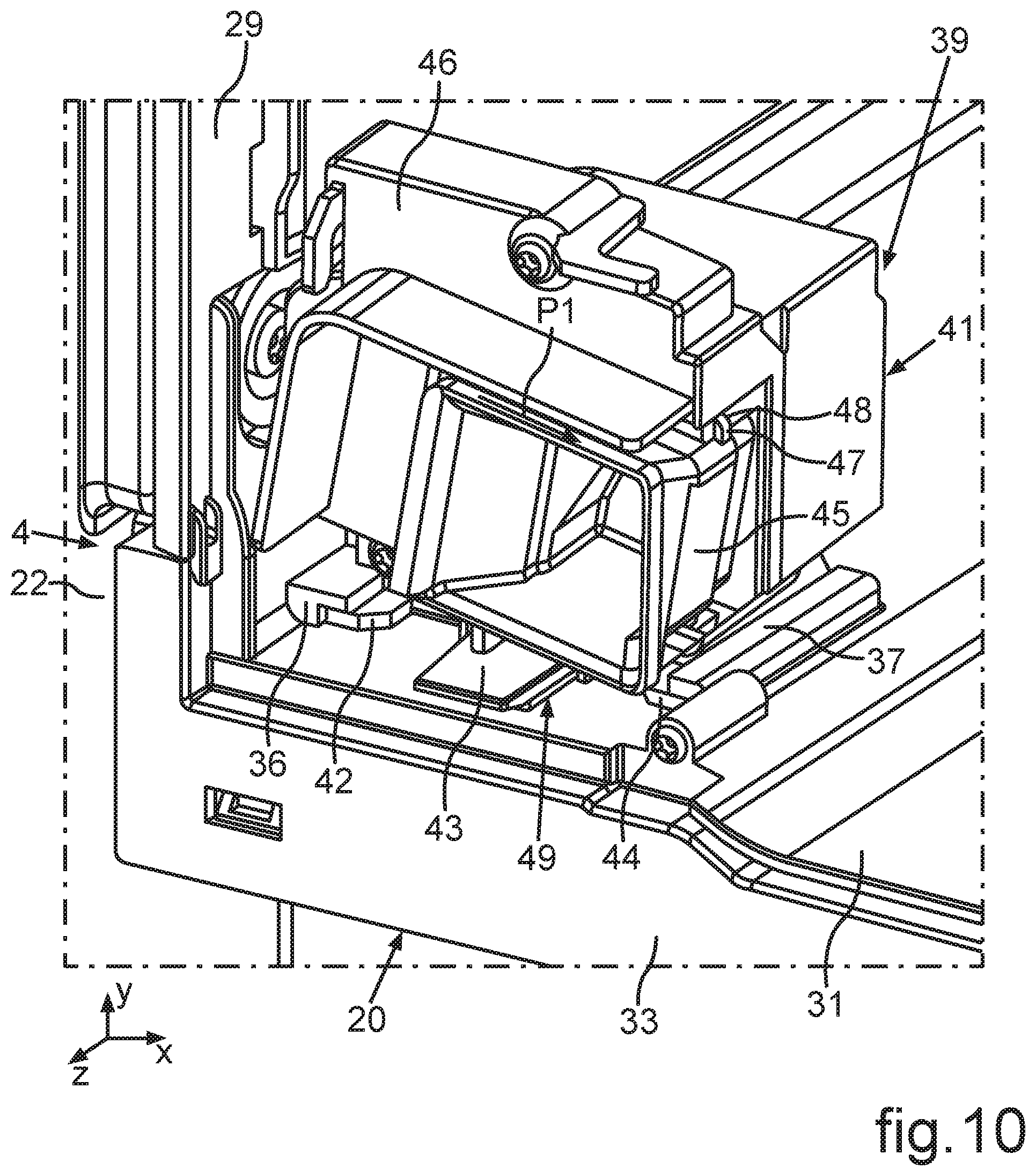
[0026] FIG. 10 a further perspective representation, in which the configuration according to FIG. 6 is installed in the interior container of the household refrigeration apparatus;
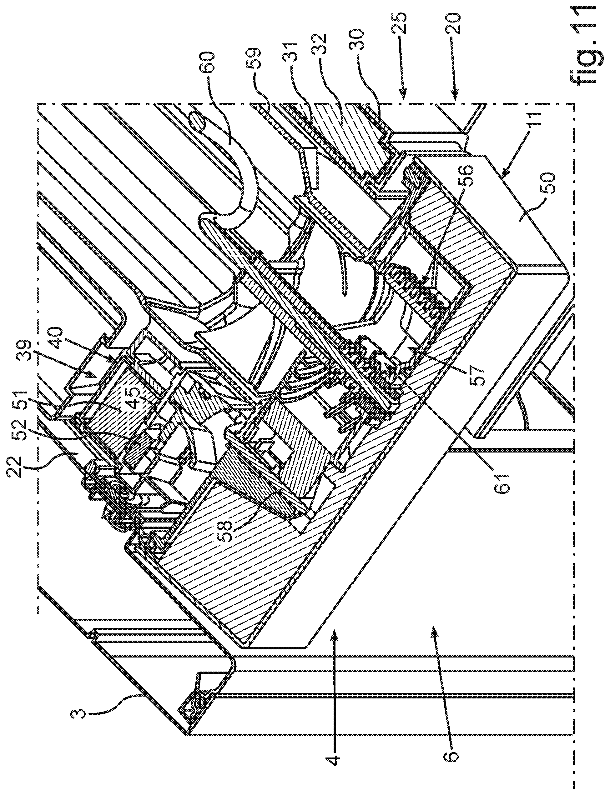
[0027] FIG. 11 a horizontal sectional representation through the household refrigeration apparatus in the area of the ice maker;
[0028] FIG. 12 a perspective view from behind to partial components of the ice maker;
[0029] FIG. 13 the representation according to FIG. 12 in a perspective different from FIG. 12;
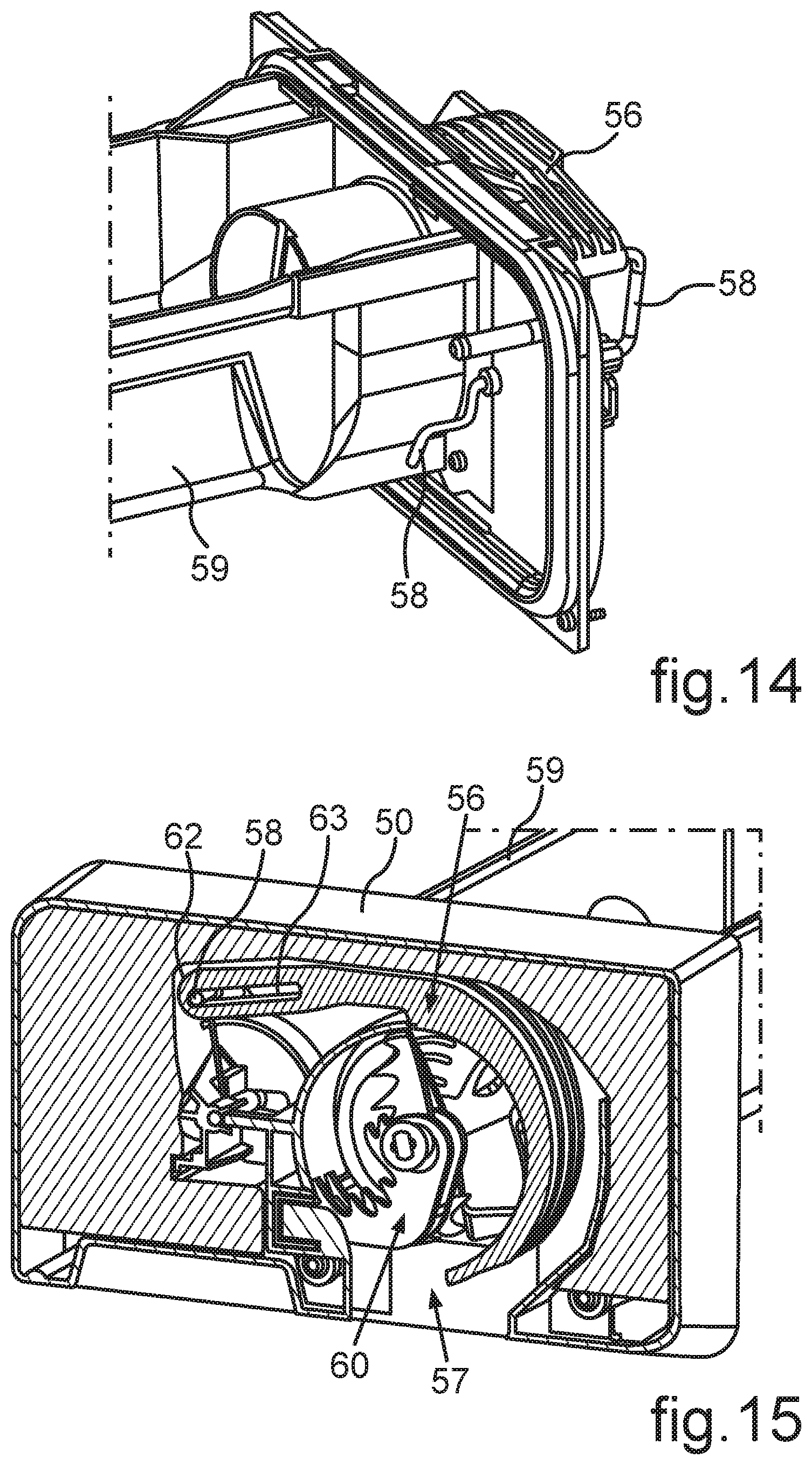
[0030] FIG. 14 an enlarged representation of partial components of the arrangement in FIG. 13;
[0031] FIG. 15 a perspective vertical sectional representation through the arrangement of the components according to FIG. 13;
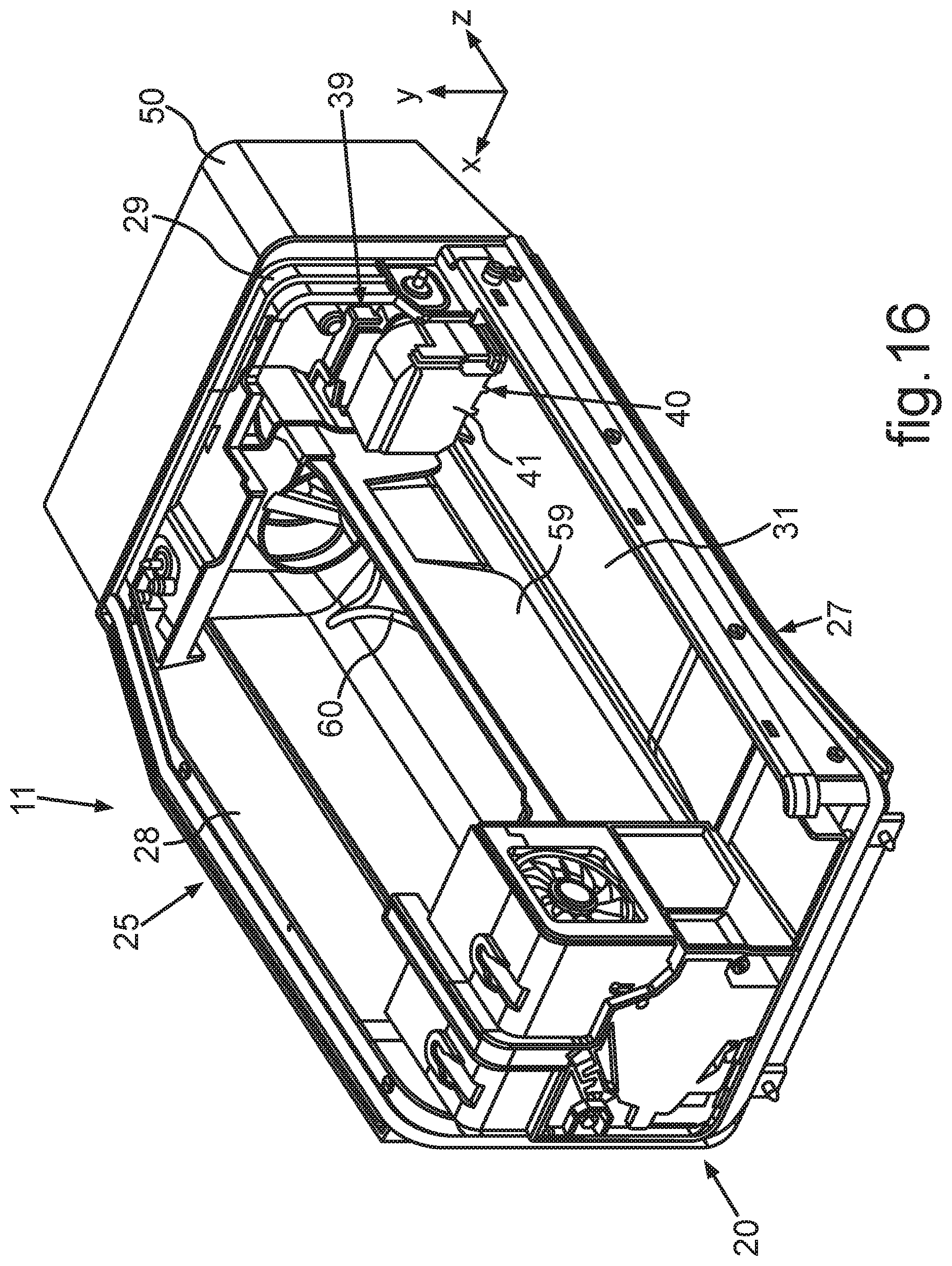
[0032] FIG. 16 a perspective representation to partial components of the ice maker; and
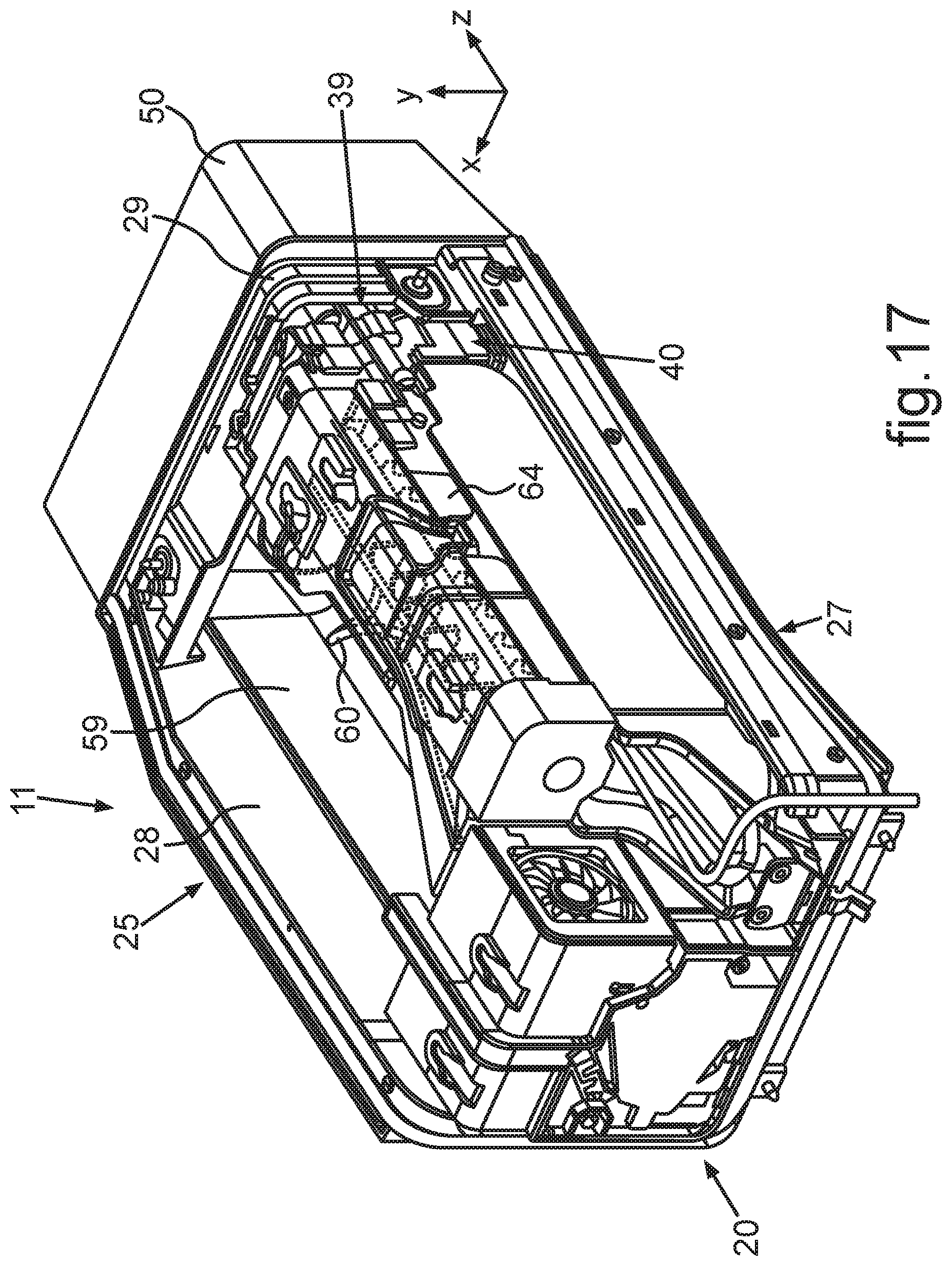
[0033] FIG. 17 a representation according to FIG. 16 with additionally assembled components of the ice maker.
DETAILED DESCRIPTION OF PREFERRED EMBODIMENTS
[0034] In the figures, identical or functionally identical elements are provided with the same reference characters.
[0035] With indications of "top", "bottom", "front", "rear", "horizontal", "vertical", "depth direction", "width direction", "height direction", etc., the positions and orientations given in intended use and intended arrangement of the apparatus are specified.
[0036] In FIG. 1, a household refrigeration apparatus 1 is shown in a simplified representation, which is formed for storing and preserving food. The household refrigeration apparatus 1 comprises a housing 2. The housing 2 comprises an exterior housing 3. Moreover, the household refrigeration apparatus 1 comprises an interior container 4 separate from the exterior housing 3. The interior container 4 is received in the exterior housing 3. A thermally insulating material such as for example insulating foam and/or a vacuum insulating panel is arranged in a clearance 5 between the exterior housing 3 and the interior container 4.
[0037] In the embodiment, the interior container 4 bounds a receiving space 6 with its walls, which is formed for receiving food. Here, the receiving space 6 is in particular formed as a refrigerating compartment.
[0038] On the front side, the interior container 4 comprises a loading opening, via which food can be taken into or be removed from the receiving space 6. In the embodiment, the receiving space 6 is closable by two separate doors 7 and 8. The two doors 7 and 8 are pivotably arranged at the housing 2. The two doors 7 and 8 are arranged in the same height position viewed in height direction (y-direction) of the household refrigeration apparatus 1. In width direction (x-direction) of the household refrigeration apparatus 1, they are arranged next to each other such that they collectively close the receiving space 6 on the front side in the closed state. In particular, these two doors 7 and 8 are arranged in a common plane in the closed state, which is spanned by the height direction and the width direction.
[0039] In FIG. 1, the door 7 on the left side with front-side view is illustrated opened and the door 8 on the right side is illustrated closed.
[0040] Advantageously, the household refrigeration apparatus 1 comprises at least one further receiving space 9 for food. This further receiving space 9 is separated from the first receiving space 6. The further receiving space 9 can for example be a freezing compartment or a keep-fresh compartment or a further refrigerating compartment. Viewed in height direction, this further receiving space 9 is formed below the first receiving space 6. The further receiving space 9 is in particular bounded by further walls of an interior container, which can also be the interior container 4. Preferably, it is provided that the further receiving space 9 is bounded by a further door 10, which is shown in the closed state in FIG. 1. Preferably, it is provided that this door 10 is formed as a front plate of a drawer linearly retractable and extendable in depth direction (z-direction) of the household refrigeration apparatus 1.
[0041] It can be provided that the household refrigeration apparatus 1 comprises multiple, separate further receiving spaces 9, and further such explained drawers are preferably formed in this context. They can adjoin to the further receiving space 9 towards the bottom viewed in height direction. They are in particular also formed within the housing 2.
[0042] Further, the door 10, in particular this front plate, is arranged in the same plane as the doors 7 and 8 in the closed state of the doors 7, 8 and 10. In particular, the doors 7, 8 and 10 are front-side vision components of the household refrigeration apparatus 1. In particular, they are also, if they are closed, arranged without overlap with each other.
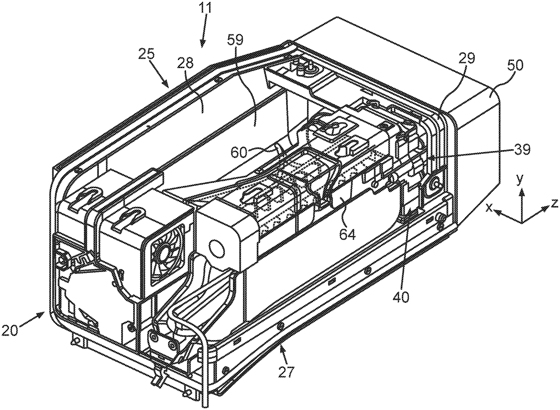
[0043] Moreover, the household refrigeration apparatus 1 comprises an ice maker 11. The ice maker 11 occupies a partial area of the volume of the receiving space 6 and is thermally insulated from the remaining volume of the receiving space 6. The ice maker 11 is formed to produce ice from water, which is supplied to the household refrigeration apparatus 1 via an external water supply line. In this context, ice form elements such as ice cubes or crushed ice can be produced.
[0044] Further, the ice maker 11 is a constituent of the dispenser unit 12 of the household refrigeration apparatus 1. In this advantageous implementation, the dispenser unit 12 comprises an output unit 13 in addition to the ice maker 11. This output unit 13 can preferably be formed at a door 7, 8. In the shown embodiment, the output unit 13 is arranged at the door 7. This is in particular advantageous because the ice maker 11 is arranged in the left upper corner area of the total volume of the receiving space 6 with front-side view of the household refrigeration apparatus 1. For outputting produced ice form elements, short paths are achieved by this local positioning. The output unit 13 is fixedly installed at the door 7. Moreover, the output unit 13 is separated from the ice maker 11 and also decoupled from it in this context. In the closed state of the door 7, ice form elements produced by the ice maker 11 can get into the output unit 13 and be output via a front side 14 of the door 7. Thereto, it is provided that a recess is formed on the front side 14, which faces away from the receiving space 6 in the closed state of the door 7. A vessel can be placed in this recess to be able to collect the output ice form elements.
[0045] Further, the dispenser unit 12 can also be formed for outputting liquid such as water or other drinks in addition to the output of ice form elements.
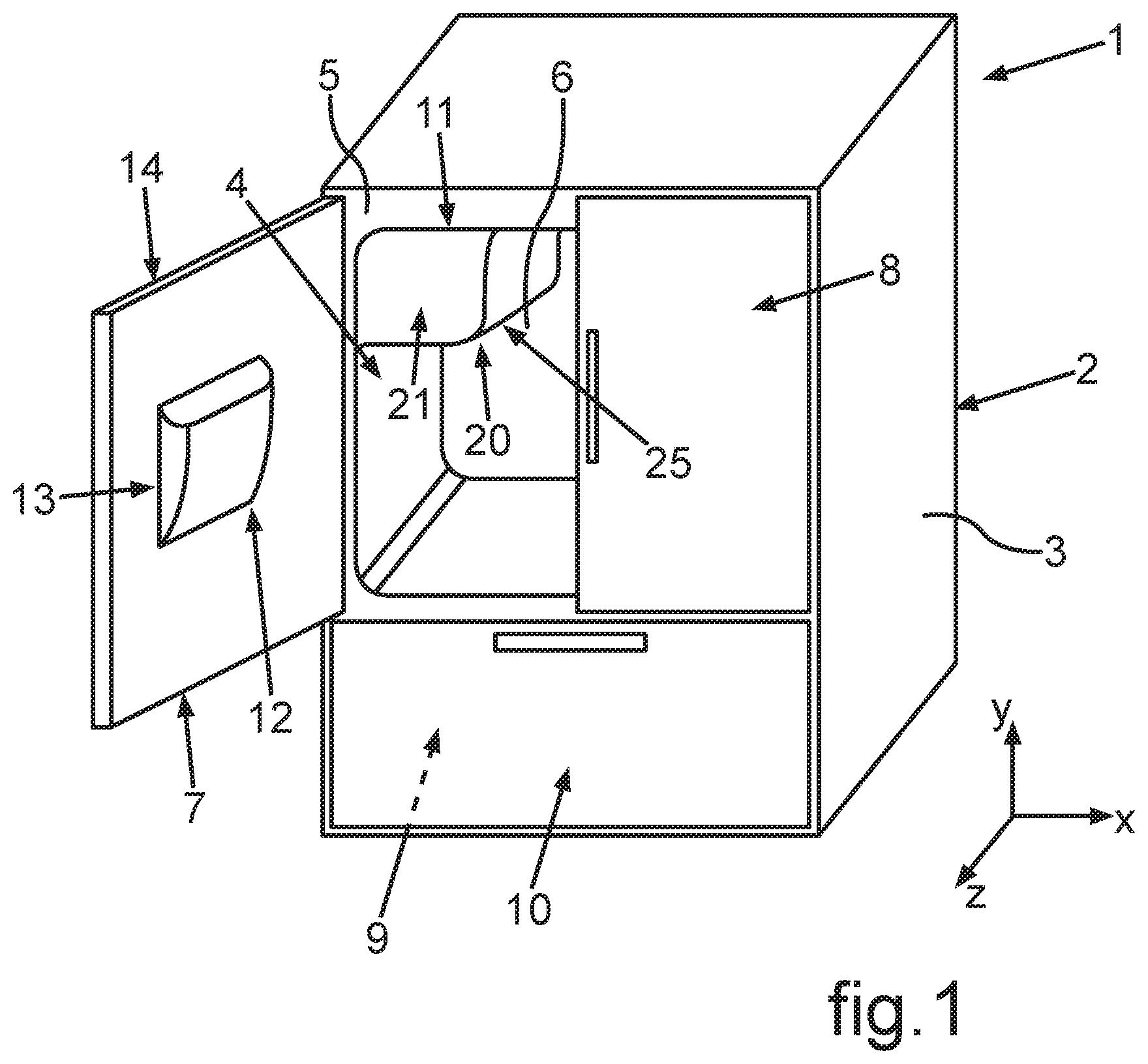
[0046] In FIG. 2, an embodiment of the interior container 4 is shown in a perspective representation. The interior container 4 is preferably integrally produced from plastic, for example by deep-drawing. Injection molding can also be provided.
[0047] The interior container 4 comprises multiple walls, which bound the receiving space 6. For example, the interior container 4 is formed with a first vertical side wall, which is a first wall 15 in the example, an opposing second vertical side wall 16, a rear wall 17, which is a third wall in the example, a bottom wall 18 and a ceiling wall, which is a second wall 19 in the example.
[0048] The first vertical side wall for example represents a first wall 15 of the interior container 4. In an embodiment, the ceiling wall represents a second wall 19 of the interior container 4, which is arranged angled, in particular at an angle of 90.degree., to the first wall 15.
[0049] The ice maker 11 comprises a housing 20 (FIG. 1). A receiving space 21 of this ice maker 11 is bounded by the housing 20. The housing 20 comprises a wall area 22 (FIG. 2) of the first wall 15 as a constituent. This wall area 22 is an upper wall area in the configuration according to FIG. 1 and FIG. 2. Moreover, a further constituent of the housing 20 of the ice maker 11 is formed by a wall area 23 of the second wall 19.
[0050] Moreover, the receiving space 21 is bounded by a further wall area 24. This further wall area 24 is an integral constituent of the rear wall 17 of the interior container 4. The wall areas 22, 23 and 24 directly join to each other.
[0051] Moreover, the housing 20 comprises a wall unit 25 (FIG. 1), which is a component separate from the interior container 4. This wall unit 25 is a further constituent of the housing 20 and bounds the receiving space 21 of the housing 20 in addition to the wall areas 22, 23 and 24.
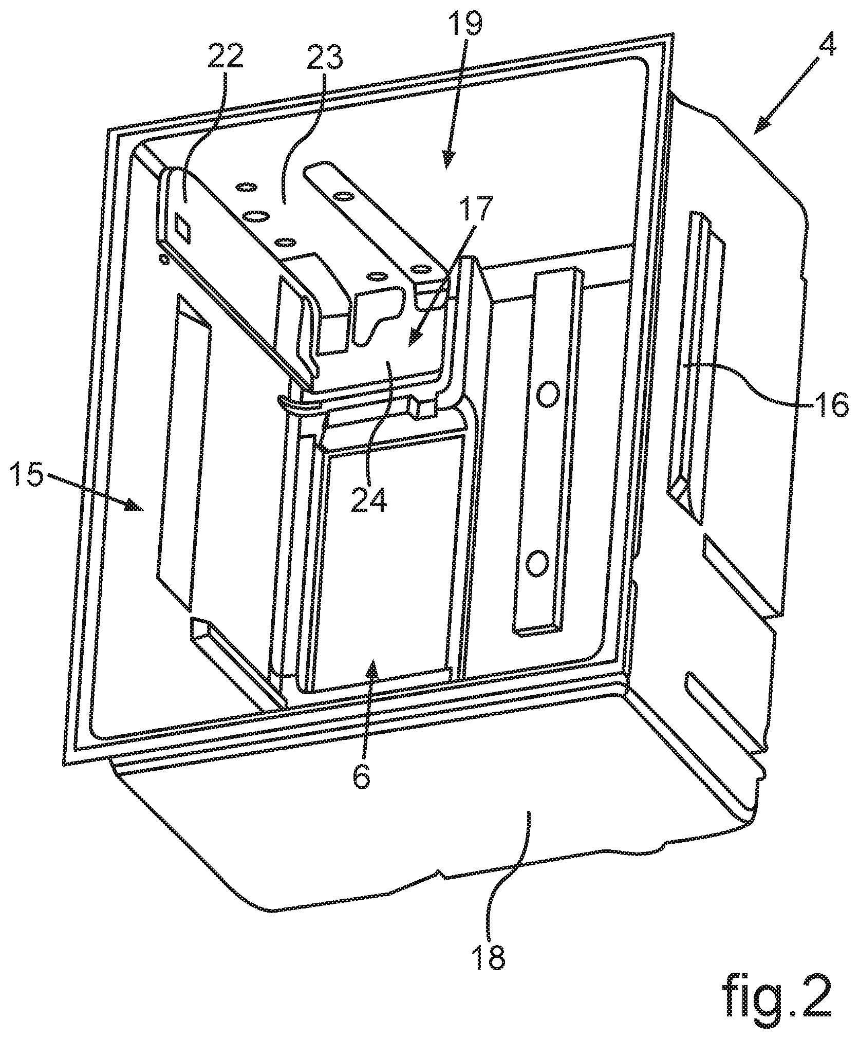
[0052] In FIG. 3, the wall unit 25 is shown in a perspective representation. It comprises a first wall plate 27 and a second wall plate 28, which form a plate unit 26. The two wall plates 27 and 28 directly join to each other and in particular at an angle of 90.degree. to each other. The first wall plate 27 is in particular horizontally oriented and the second wall plate 28 is vertically oriented. In a vertical section, in which the sectional plane is formed by the width direction (x-direction) and the height direction (y-direction) of the household refrigeration apparatus 1 and also of the ice maker 11 in this context, this plate unit 26 has an L-shape.
[0053] In the shown embodiment, the wall unit 25 also comprises an L-shaped positioning bracket 29. It is connected to the wall plate 28 on the one hand and to the wall plate 27 on the other hand with its ends. In depth direction (z-direction), this positioning bracket 29 is arranged in a front area and thus in a front end of this wall unit 25. It bounds a front-side opening of this wall unit 25 with the front area of the wall plates 27 and 28. The wall plates 27 and 28 are formed with an integral, L-shaped outer wall element 30 and an L-shaped and integral inner wall element 31 separate therefrom. In a clearance between the outer wall element 30 and the inner wall element 31, a thermally insulating material 32 is introduced. Thereby, the receiving space 21 of the ice maker 11 is thermally insulated from the remaining volume of the receiving space 6. A front-side, also L-shaped end flange 33 covers this clearance between the outer wall element 30 and the inner wall element 31 on the front side.
[0054] As is apparent in FIG. 3, an assembly area 34 for a drive unit of the ice maker 11 is formed at the first wall plate 27, in particular at the inner wall element 31. The drive unit, which is not yet illustrated in FIG. 3, is formed for moving a flap. An opening can be closed by this flap, from which ice can be output from the housing 20 of the ice maker 11, in particular can be output into the output unit 13.
[0055] Components of a mechanically, non-destructively detachable connection 35 are formed in the assembly area 34. The connection 35 can be formed to the effect that it is only formed for directly plugging components together. However, this plug connection can additionally also be formed as a locking connection and a locking can then additionally be provided besides simply plugging together. Thus, a locking connection is in particular also understood by a plug connection.
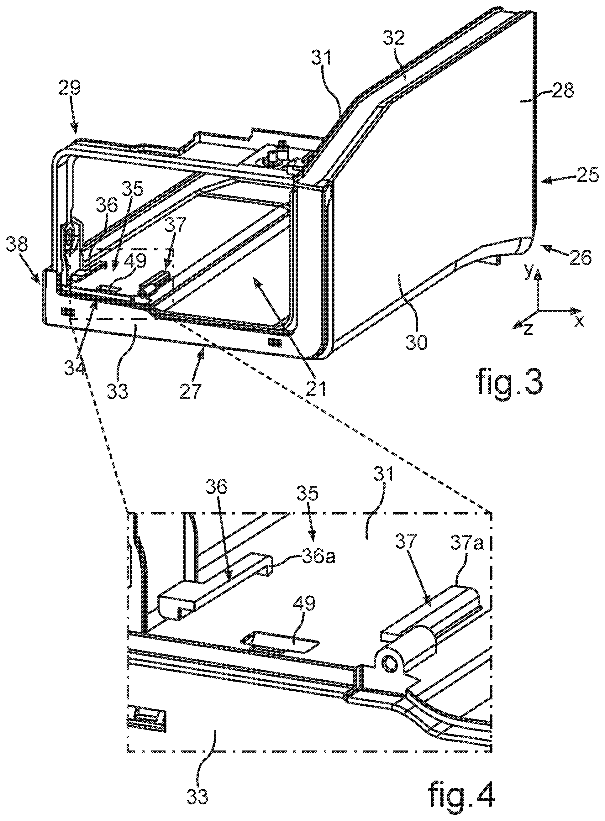
[0056] This connection 35 comprises mating plug elements 36 and 37. These mating plug elements 36 and 37 are in particular formed integrally with the inner wall element 31. The mating plug elements 36 and 37 are formed as plug rails in the embodiment. They are oriented parallel to each other and extend linearly in depth direction. Moreover, it is provided that the assembly area 34 is formed in the front area viewed in depth direction of the housing 21. In particular, this assembly area 34 and thus also the connection 35 to the mating plug elements 36 and 37 is formed in a front third of length of the wall unit 25. This means that these mating plug elements 36 and 37 are formed in a front third of length of this entire length of the wall unit 25 upon length view of the wall unit 25 in depth direction. In particular, the mating plug elements 36 and 37 are thus formed in a front third of length of the housing 21 and thus also of the entire ice maker 11.
[0057] In an implementation, it is provided that the mating plug elements 36 and 37 are formed in a corner area 38 with front-side view of the wall unit 25 and thus with view in depth direction. In particular, this corner area 38 is a left-side, lower corner area with this front-side view.
[0058] In FIG. 4, that partial area of the representation in FIG. 3 is shown enlarged, in which the mating plug elements 36 and 37 are formed. As is apparent, these mating plug elements 36 and 37 each comprise a rear stop 36a, 37a. These stops 36a, 37a thus limit the depth of this plug-in length. The plug elements of the plug connection not shown in FIG. 3 and FIG. 4 can be plugged in over this plug-in length and thus be mechanically coupled to these mating plug elements 36 and 37.
[0059] In FIG. 5, a drive unit 39 of the ice maker 11 is shown in a perspective representation. This drive unit 39 is constructed as a compact module 40. This drive unit 39 comprises a module housing 41. It is in particular formed of plastic. The module housing 41 advantageously comprises plug elements 42, 43 and 44 formed integrally therewith. These separate plug elements 42 to 44 are a further constituent of the plug connection 35. In particular, the plug elements 42, 44 are formed as plug runners in the embodiment.
[0060] They are formed in a lower area of the module housing 41.
[0061] The drive unit 39 moreover comprises an actuating element 45. The actuating element 45 is a separate component, which is movably arranged. Here, it is in particular linearly displaceable. Here, the actuating element 45 is arranged obliquely inclined and thus can be moved on an obliquely inclined linear guiding track relative to a retaining unit 46 of the drive unit 39. Here, the actuating element 45 is formed as a duct-like box. The direction of movement of the actuating element 45 relative to the retaining unit 46 is shown by the arrow P1.
[0062] Further, the actuating element 45 comprises at least one engagement element 47, which is guided in a guiding groove 48 of the retaining unit 46. In particular, an upper engagement element 47 and a lower engagement element 47 as well as an upper guiding groove 48 and a lower guiding groove 48 are formed.
[0063] As is moreover apparent in FIG. 3 and FIG. 4, the connection 35 comprises a receptacle 49. The receptacle 49 is formed in the inner wall element 31 and formed between the mating plug elements 36 and 37 viewed in width direction.
[0064] In FIG. 6, the assembled state of the module 40 at the wall unit 25 is shown in a perspective representation. Thus, the drive unit 39 is arranged in a front area of the housing 21, in particular in a front third of length of this housing 20. As it is apparent in FIG. 6, a secure retention is achieved by the mechanical coupling of the plug elements 42, 43 to the mating plug elements 36 and 37 and the receptacle 49. In particular, it is provided that the drive unit 39 and thus the module 40 are arranged at the wall unit 25 only by this connection 35. Additional separate fixing elements such as for example screws or the like are not provided.
[0065] As is apparent in FIG. 6, the plug element 42 formed as a plug runner is coupled to the mating plug element 36 and inserted into it up to the stop 36a. The further plug element 44 formed spaced thereto is inserted into the mating plug element 37, in particular up to the stop 37a.
[0066] Such a configuration would already be sufficient to allow the secure retention of the module 40 at the wall unit 25. In an advantageous implementation, it is provided that the element 43 is present in addition to these plug elements 42, 44 and the mating plug elements 36 and 37. It is preferably formed with a locking element 43a. This locking element 43a plunges into the receptacle 49 in the assembled state, as it is shown in FIG. 6, and snaps therein or locks therein. An even better positional fixing of the module 40 at the wall unit 25 is thereby achieved. Thus, secure positioning of the module 40 at the wall unit 25 is in particular achieved in all three spatial directions. In particularly advantageous manner, simple detachment of the module 40 from the assembled final position shown in FIG. 6 is also allowed.
[0067] In that the element 43 is actuated at its front-side edge, in particular upward bent, this snapped or locked state can be detached and then the module 40 can be forward pulled by a movement linear viewed in depth direction.
[0068] In the assembly, thus, this module 40 is provided and the wall unit 25 is also provided. For assembling this drive unit 39 to the wall unit 25, this module 40 is displaced into the wall unit 25 coming from the front. Thereto, the plug elements 42 and 44 are coupled to the mating plug elements 36 and 37. Upon then guided linear displacement of the module 40 in depth direction to the rear, the plug elements 42 and 44 are moved until they have reached the stops 36a and 37a. Snapping of the locking element 43a in the receptacle 49 is then also automatically achieved on this movement path.
[0069] In FIG. 7, the module 40 is shown in the assembled state in a vertical sectional representation. This vertical section is formed in a rear area of the module 40 such that the snapped state of the locking element 43a in the receptacle 49 is not apparent.
[0070] In FIG. 8, the wall unit 25 with the module 40 assembled thereto is shown in a further vertical sectional representation. Here, the sectional plane is given by the height direction and the depth direction. Moreover, the sectional representation in FIG. 8 is also perspectively shown. In contrast to the representation according to FIG. 6, moreover, a front-side cover 50 is additionally illustrated, which represents a front-side frame. The front flange 33 and the positioning bracket 29 are covered on the front side by this cover 50.
[0071] In this representation, the snapped state between the locking element 43a of the element 43 and the receptacle 49 is shown.
[0072] Moreover, it is also apparent that the drive unit 39 comprises a motor 51, which is arranged in the module housing 41. In the embodiment, it is provided that the drive unit 39 moreover comprises a cam 52. The cam 52 is coupled to the motor 51. On the other hand, the cam 52 is coupled to the actuating element 45. The cam 52 is set in a rotational movement by the motor 51. By this rotational movement, the actuating element 45 is actuated. Therein, the coupling between the cam 52 and the actuating element 45 is such that the rotational movement of the cam 52 is converted to a linear movement according to the arrow P1.
[0073] In FIG. 9, the drive unit 39 is shown in a horizontal sectional representation. As is here apparent, a shaft 53 of the motor 51 engages with the cam 52. The cam 52 comprises a pin-like coupling element 54, which engages with a receptacle 55 of the actuating element 45.
[0074] In FIG. 10, the housing 20 of the ice maker 11 is shown in a further perspective representation. Therein, the wall unit 25 is assembled to the interior container 4 in the upper left corner area. In particular, the actuating element is also guided in the lower area by the coupling between a guiding groove or guiding track 48 and an engagement element 47, as it is shown in FIG. 8.
[0075] In FIG. 11, a partial area of the household refrigeration apparatus 1 is illustrated in a horizontal sectional representation (the sectional plane is formed by the width direction and the depth direction). The ice maker 11 is shown in the installed state in the household refrigeration apparatus 1. As is apparent, the module 40 is arranged in a near area to a flap 56. The flap 56 is an ice flap, which closes or unblocks an opening 57 of the housing 20. The flap 56 is movably arranged and movable by the drive unit 39. As is in particular apparent in FIG. 11, this flap 56 is arranged in a front area of the ice maker and thus also of the housing 20. The module 40 is arranged directly adjacent to this flap 56, which is preferably also located in the front third of the length of the housing 20 measured in depth direction. By this immediately adjacent arrangement between the module 40 and the flap 56, very short paths arise, to be able to actuate this flap 56 by the drive unit 39 via mechanical coupling. As is apparent in this context, the ice maker 11 comprises a very short lever rod 58. This lever rod 58 is directly connected to the actuating element 45. On the other hand, this lever rod 58 is connected to the flap 56.
[0076] In the representation according to FIG. 11, a container or a collecting pan 59 is furthermore shown. The produced ice form elements, in particular the ice cubes, can be stored in the ice maker 11 in this collecting pan 59 until they can be transported out of the housing 20. Thereto, a screw conveyor 60 is provided. The ice form elements can be transported forward into the collecting pan 59 viewed in depth direction by this screw conveyor 60 until they get into the opening 57. If it is to be provided that these ice form elements are crushed and for example crushed ice is produced, these ice form elements are crushed by a crushing device 61, which is arranged adjacent to the opening 57.
[0077] The flap 56 is opened or closed depending on need such that the ice form elements or the crushed ice can be output via the opening 57 or this is prevented.
[0078] As is moreover apparent in FIG. 11, the module 40 is arranged next to this collecting pan 49 viewed in width direction (x-direction). Thus, the module 40 is arranged directly adjacent and lateral to this collecting pan 59 viewed in width direction. Viewed in depth direction, the module 40 is arranged overlapping with the collecting pan 59 in particular over its entire length. Thereby, a compact construction of the housing 20 is achieved in depth direction.
[0079] In FIG. 12, an arrangement of multiple components of the ice maker is shown in a perspective representation viewed from behind. The lever rod 58 is shown.
[0080] In FIG. 13, the configuration of the components according to FIG. 12 is shown in a perspective different from FIG. 12.
[0081] In FIG. 14, partial elements of the representation in FIG. 13 are shown, wherein the front cover 50 is removed hereto. Here, the flap 56 is shown with its upper area. The lever rod 58 is also illustrated.
[0082] In FIG. 15, the arrangement is shown in a perspective sectional representation along the sectional line XV-XV in FIG. 13. This flap 56 comprises a receptacle 63 at its end 62 facing away from the opening 57 and facing the module 40. The lever rod 58 engages with this receptacle 63. In particular, this receptacle 63 is formed as an elongated hole. By the movement transmission of the movement of the cam 52 to the actuating element 45, the lever rod 58 coupled thereto is actuated, in particular rotated, such that by the coupling of the lever rod 58 to the flap 56, this flap 56 is moved between the opened position and the closed position.
[0083] In FIG. 16, the ice maker 11 is shown with partial components. These partial components are shown in a perspective representation with view from behind. In this perspective representation, the front-side position of the entire module 14 immediately in the near area to the flap 56 is apparent. Here, the arrangement of the module 40 in the front third of length of the length of the housing 20 measured in depth direction is in particular also apparent.
[0084] In FIG. 17, the representation according to FIG. 16 is shown, wherein additional further components of the ice maker 11 are installed in the housing 20 in FIG. 17. In particular, this is an ice form tray 64, into which water can be introduced. The water introduced into form areas of this ice form tray 64 freezes. The thus produced ice form elements can then be removed from the ice form tray 64 and be introduced into the collecting pan 59. In particular, the lever rod 58 is a coupling rod. The coupling rod is in turn a constituent of a coupling device, by which the drive unit 39 is mechanically coupled to the flap 56.
[0085] In a further embodiment, the housing has a depth direction, and the opening is arranged in a front third of depth of the entire depth of the housing and the module of the drive unit is arranged in this front third of depth. Preferably, the housing has a depth direction, and the housing comprises a front flange, wherein the module is arranged adjacent to the front flange. Preferably, the housing has a depth direction, and the module is arranged in a front-side corner area of the interior of the housing with front-side view of the ice maker in this depth direction. Preferably, the module is arranged in a left lower, front-side corner area of the interior.
[0086] In a further embodiment, the ice maker comprises a collecting pan for ice form elements, wherein the collecting pan is arranged in the housing and the module of the drive unit is arranged laterally directly next to the collecting pan viewed in width direction of the ice maker.
[0087] In a further embodiment, the coupling device comprises a coupling rod, which is connected to the flap and to the module of the drive unit. In particular, the flap comprises an engagement slit at an end, with which the coupling rod engages. Preferably, the flap is formed shovel-like and curved. Preferably, the module of the drive unit comprises a module housing, which is non-destructively detachably arranged at the housing.
[0088] In a further embodiment, the module housing is fixed to the housing by a mechanical connection, which is a plug connection or a locking connection or a plug and locking connection. Preferably, the mechanical connection comprises at least one plug runner and one plug rail, which can be plugged together by a linear relative movement to each other.
[0089] In a further embodiment, the plug runner is formed integrally with the module housing and the plug rail is formed integrally with the housing.
[0090] In a further embodiment, the drive unit comprises a motor and an actuating element, which is coupled to the motor, wherein the actuating element is coupled to the flap.
List of Reference Characters
[0091] 1 Household refrigeration apparatus [0092] 2 housing [0093] 3 exterior housing [0094] 4 interior container [0095] 5 clearance [0096] 6 receiving space [0097] 7 door [0098] 8 door [0099] 9 receiving space [0100] 10 door [0101] 11 ice maker [0102] 12 dispenser unit [0103] 13 output unit [0104] 14 front side [0105] 15 side wall [0106] 16 side wall [0107] 17 rear wall [0108] 18 bottom wall [0109] 19 ceiling wall [0110] 20 housing [0111] 21 receiving space [0112] 22 wall area [0113] 23 wall area [0114] 24 wall area [0115] 25 wall unit [0116] 26 plate unit [0117] 27 wall plate [0118] 28 wall plate [0119] 29 positioning bracket [0120] 30 outer wall element [0121] 31 inner wall element [0122] 32 thermally insulating material [0123] 33 end flange [0124] 34 assembly area [0125] 35 plug connection [0126] 36 mating plug element [0127] 36a stop [0128] 37 mating plug element [0129] 37a stop [0130] 38 corner area [0131] 39 drive unit [0132] 40 module [0133] 41 module housing [0134] 42 plug element [0135] 43 plug element [0136] 43a locking element [0137] 44 plug element [0138] 45 actuating element [0139] 46 retaining unit [0140] 47 engagement element [0141] 48 guiding groove [0142] 49 receptacle [0143] 50 cover [0144] 51 motor [0145] 52 cam [0146] 53 shaft [0147] 54 coupling element [0148] 55 receptacle [0149] 56 flap [0150] 57 opening [0151] 58 lever rod [0152] 59 container [0153] 60 screw conveyor [0154] 61 crushing device [0155] 62 end [0156] 63 receptacle [0157] 64 ice form tray
* * * * *
D00000
D00001
D00002
D00003
D00004
D00005
D00006
D00007
D00008
D00009
D00010
D00011
D00012
XML
uspto.report is an independent third-party trademark research tool that is not affiliated, endorsed, or sponsored by the United States Patent and Trademark Office (USPTO) or any other governmental organization. The information provided by uspto.report is based on publicly available data at the time of writing and is intended for informational purposes only.
While we strive to provide accurate and up-to-date information, we do not guarantee the accuracy, completeness, reliability, or suitability of the information displayed on this site. The use of this site is at your own risk. Any reliance you place on such information is therefore strictly at your own risk.
All official trademark data, including owner information, should be verified by visiting the official USPTO website at www.uspto.gov. This site is not intended to replace professional legal advice and should not be used as a substitute for consulting with a legal professional who is knowledgeable about trademark law.