Axial Fan And Electrical Device
YASUMOTO; Nobuaki ; et al.
U.S. patent application number 16/695085 was filed with the patent office on 2020-05-28 for axial fan and electrical device. This patent application is currently assigned to NIDEC CORPORATION. The applicant listed for this patent is NIDEC CORPORATION. Invention is credited to Toshifumi FUKUI, Toshikazu FUKUNAGA, Yang LIU, Zhengyi XIA, Nobuaki YASUMOTO, Chenghui YU.
| Application Number | 20200166040 16/695085 |
| Document ID | / |
| Family ID | 67426616 |
| Filed Date | 2020-05-28 |


| United States Patent Application | 20200166040 |
| Kind Code | A1 |
| YASUMOTO; Nobuaki ; et al. | May 28, 2020 |
AXIAL FAN AND ELECTRICAL DEVICE
Abstract
Embodiments of the disclosure provide an axial fan and an electrical device. A center of a radial inner surface and a center of a radial outer surface of a cylindrical portion of a housing of the axial fan are disposed at different positions.
| Inventors: | YASUMOTO; Nobuaki; (Kyoto, JP) ; LIU; Yang; (Dalian, CN) ; YU; Chenghui; (Dalian, CN) ; FUKUNAGA; Toshikazu; (Kyoto, JP) ; XIA; Zhengyi; (Dalian, CN) ; FUKUI; Toshifumi; (Kyoto, JP) | ||||||||||
| Applicant: |
|
||||||||||
|---|---|---|---|---|---|---|---|---|---|---|---|
| Assignee: | NIDEC CORPORATION Kyoto JP |
||||||||||
| Family ID: | 67426616 | ||||||||||
| Appl. No.: | 16/695085 | ||||||||||
| Filed: | November 25, 2019 |
| Current U.S. Class: | 1/1 |
| Current CPC Class: | F04D 29/522 20130101; F04D 29/541 20130101; F04D 29/52 20130101; F04D 19/002 20130101; F04D 25/08 20130101; F05D 2250/51 20130101 |
| International Class: | F04D 19/00 20060101 F04D019/00; F04D 25/08 20060101 F04D025/08; F04D 29/52 20060101 F04D029/52 |
Foreign Application Data
| Date | Code | Application Number |
|---|---|---|
| Nov 28, 2018 | CN | 201821979346.0 |
Claims
1. An axial fan, comprising: a motor comprising a shaft rotatable about a central axis; an impeller fixed to the shaft; and a housing comprising a cylindrical portion disposed on a radial outer side of the impeller and extending in an axial direction, wherein a center of an axial projection of a radial inner surface of the cylindrical portion is a first center, the first center being located on the central axis, and a center of an axial projection of a radial outer surface of the cylindrical portion is a second center, the second center being at a position different from a position of the first center in a direction perpendicular to the central axis.
2. The axial fan according to claim 1, wherein in the direction perpendicular to the central axis, a radial width of a first region of the cylindrical portion that is disposed on a second center side based on the first center is greater than a radial width of a second region of the cylindrical portion that is disposed on an opposite side of the second center based on the first center, and a housing recess that is recessed in the axial direction is formed in the first region.
3. The axial fan according to claim 2, wherein a plurality of housing recesses are formed in a circumferential direction.
4. The axial fan according to claim 3, wherein a first rib is disposed between the plurality of housing recesses.
5. The axial fan according to claim 2, wherein the housing further comprises: a base that overlaps with the motor in the axial direction; and a second rib connecting the base and the radial inner surface of the cylindrical portion, wherein the second rib and the housing recess are provided at different positions in a circumferential direction.
6. The axial fan according to claim 2, wherein in a direction toward an air outlet of the axial fan, the radial inner surface of the first region of the cylindrical portion inclines in a direction away from the central axis.
7. The axial fan according to claim 1, wherein the cylindrical portion comprises a cylindrical inner wall extending in the axial direction, and a cylindrical outer wall that is disposed on a radial outer side of the inner wall and extends in the axial direction, the inner wall comprises the radial inner surface, and the outer wall comprises the radial outer surface, and the inner wall and the outer wall are connected by a third rib extending in a radial direction.
8. The axial fan according to claim 1, wherein the housing further comprises: an edge portion extending to the radial outer side from an end of the cylindrical portion that is close to an air outlet of the axial fan in the axial direction, and a center of an axial projection of the edge portion is the second center.
9. An electrical device, comprising the axial fan according to claim 1.
Description
CROSS-REFERENCE TO RELATED APPLICATION
[0001] The present invention claims priority under 35 U.S.C. .sctn. 119 to Chinese Application No. 201821979346.0 filed on Nov. 28, 2018 the entire content of which is incorporated herein by reference.
BACKGROUND
Technical Field
[0002] The disclosure relates to the measurement field, and in particular, to an axial fan.
Description of Related Art
[0003] In the conventional art, a cooling fan is mounted in the housing of various electrical products to cool the electronic components of the electrical product. Because heat generated by the electronic components increases as the performance improves, and the layout density increases as the size of the housing decreases, static pressure and flow of the cooling fan need to be increased. In order to meet this requirement, in recent years, an axial fan has been used as a cooling fan to ensure a large static pressure and an increased flow.
[0004] It should be noted that, the above introduction of the technical background is only for the purpose of facilitating a clear and complete description of the technical solutions of the disclosure and facilitating the understanding by those skilled in the art. The above technical solutions are not considered to be well known to those skilled in the art simply because these solutions are described in the background section of the disclosure.
[0005] When the foregoing existing axial fan is mounted to an actual electrical device, the air flow inside the electrical device may be impeded due to the arrangement of other components of the electrical device. As a result, fluidity of air on a side of the electrical device is relatively poor.
SUMMARY OF THE INVENTION
[0006] According to an embodiment of the disclosure, an axial fan is provided, and the axial fan includes: a motor having a shaft that can rotate about a central axis; an impeller fixed to the shaft; and a housing having a cylindrical portion disposed on a radial outer side of the impeller and extending in an axial direction, wherein a center of an axial projection of a radial inner surface of the cylindrical portion is a first center, the first center being located on the central axis; and a center of an axial projection of a radial outer surface of the cylindrical portion is a second center, the second center being at a position different from a position of the first center in a direction perpendicular to the central axis.
[0007] The above and other elements, features, steps, characteristics and advantages of the present disclosure will become more apparent from the following detailed description of the preferred embodiments with reference to the attached drawings.
BRIEF DESCRIPTION OF THE DRAWINGS
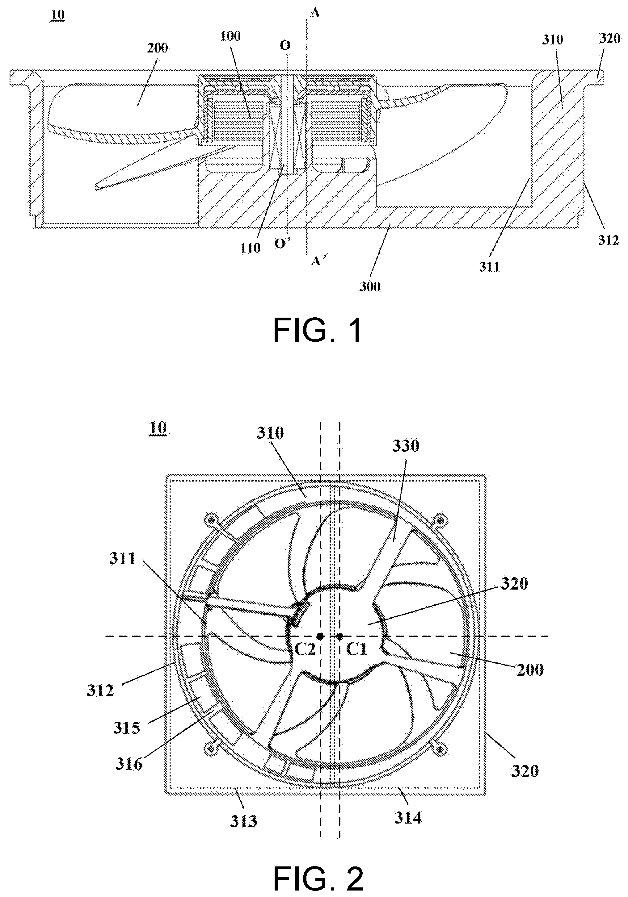
[0008] FIG. 1 is a cross-sectional view of an axial fan according to an embodiment of the disclosure.
[0009] FIG. 2 is a bottom view of an axial fan according to Embodiment 1 of the disclosure.
[0010] FIG. 3 is a perspective view of the axial fan according to Embodiment 1 of the disclosure.
[0011] FIG. 4 is a schematic diagram of a relative position of an internal structure of an electrical device according to Embodiment 2 of the disclosure.
DESCRIPTION OF THE EMBODIMENTS
[0012] The foregoing and other features of the disclosure will become apparent from the following specification with reference to the accompanying drawings. Specific implementations of the disclosure are disclosed in the specification and the accompanying drawings, which illustrate some implementations in which the principles of the disclosure may be adopted. It should be understood that, the disclosure is not limited to the implementations described, and conversely, the disclosure includes all modifications, variations and equivalents that fall within the scope of the appended claims.
[0013] In the embodiments of the disclosure, for convenience of description, a direction parallel to a central axis is referred to as an "axial direction", a radial direction that is centered on the central axis is referred to as a "radial direction", and a direction around the central axis is referred to as a "circumferential direction". However, the above is merely for convenience of description and is not intended to limit the orientation of the axial fan during use and manufacture.
[0014] The following describes the axial fan in the embodiments of the disclosure with reference to the accompanying drawings.
[0015] FIG. 1 is a cross-sectional view of an axial fan according to an embodiment of the disclosure. FIG. 2 is a bottom view of an axial fan according to Embodiment 1 of the disclosure. FIG. 3 is a perspective view of the axial fan according to Embodiment 1 of the disclosure.
[0016] As shown in FIG. 1 and FIG. 2, the axial fan 10 includes: a motor 100 having a shaft 110 that can rotate about a central axis OO'; an impeller 200 fixed to the shaft 110; and a housing 300 having a cylindrical portion 310 disposed on a radial outer side of the impeller 200 and extending in the axial direction. A center of an axial projection of a radial inner surface 311 of the cylindrical portion 310 is a first center C1, and the first center is located on the central axis OO'. A center of an axial projection of a radial outer surface 312 of the cylindrical portion 310 is a second center C2, and the second center C2 is at a position different from the position of the first center C1 in a direction perpendicular to the central axis OO'.
[0017] In the present embodiment, the first center C1 is located on the central axis OO', the second center is located on an axis AA' of the radial outer surface 312 of the cylindrical portion 310, and the axis AA' is deviated relative to the central axis OO' in a direction perpendicular to the axial direction.
[0018] In the present embodiment, a direction of a relative offset between the first center C1 and the second center C2 and the offset may be set according to the actual requirement.
[0019] In this way, the first center C1 of the radial inner surface 311 and the second center C2 of the radial outer surface 312 are disposed at different positions, so that a component that impedes flowing of air in the electrical device can be avoided to some extent, thereby improving air supply efficiency.
[0020] In the present embodiment, for the structures of the motor 100 and the impeller 200, please refer to the related art. In addition, the axial fan 10 may further include some other existing components. The descriptions thereof are omitted herein.
[0021] In the present embodiment, as shown in FIG. 2, in the direction perpendicular to the central axis OO', a radial width of a first region 313 of the cylindrical portion 310 that is disposed on the side of the second center C2 (the left side in FIG. 2) based on the first center C1 is greater than a radial width of a second region 314 of the cylindrical portion 310 that is disposed on the opposite side of the second center C2 based on the first center C1. That is, the left side portion of the cylindrical portion 310 in FIG. 2 is thicker, and the right side portion is thinner. In addition, a housing recess 315 that is recessed in the axial direction is formed in the first region 313.
[0022] In this way, the weight of the housing can be reduced and shrinkage generated during molding can be prevented.
[0023] As shown in FIG. 2, a plurality of housing recesses 315 are formed in the circumferential direction. The quantity and the size of the housing recess 315 may be set according to the actual requirement.
[0024] In the present embodiment, as shown in FIG. 2, a first rib 316 is disposed between the plurality of housing recesses 315. In this way, the rigidity of the housing can be improved.
[0025] In the present embodiment, as shown in FIG. 2, the housing 300 may further include: a base 320 that overlaps with the motor 100 in the axial direction; and a second rib 330 connecting the base 320 and the radial inner surface 311 of the cylindrical portion 310, wherein the second rib 330 is at a position different from the position of the housing recess 315 in the circumferential direction.
[0026] In this way, the rigidity of the housing can be improved.
[0027] As shown in FIG. 2, a plurality of second ribs 330 may be disposed in the circumferential direction, and the quantity of second ribs 330 may be determined according to the actual requirement.
[0028] In the present embodiment, the radial inner surface 311 of the first region 313 of the cylindrical portion 310 may be designed to incline in a direction away from the central axis OO' in a direction toward an air outlet of the axial fan 10 (an upward direction in FIG. 1). In this way, an airflow from an upper surface of the axial fan can be aggregated from the first center C1 to the second center C2, thereby reducing exhaust resistance.
[0029] In the present embodiment, as shown in FIG. 3, the housing 300 may further include: an edge portion 320 extending to the radial outer side from an end (an upper end in FIG. 1) of the cylindrical portion 310 that is close to the air outlet of the axial fan 10 in the axial direction, wherein a center of an axial projection of the edge portion 320 is the second center C2. In this way, installation precision of the axial fan during installation can be improved.
[0030] In addition, the cylindrical portion 310 may include a cylindrical inner wall extending in the axial direction, and a cylindrical outer wall disposed on a radial outer side of the inner wall and extending in the axial direction. The inner wall includes the radial inner surface 311, and the outer wall includes the radial outer surface 312, and the inner wall and the outer wall may be connected by a third rib (not shown) extending in the radial direction. In this way, the rigidity of the housing can be improved while reducing the weight of the housing.
[0031] It can be known from the foregoing embodiment that, the center of the radial inner surface and the center of the radial outer surface of the cylindrical portion of the housing of the axial fan are disposed at different positions, so that the component that impedes flowing of air in the electrical device can be avoided to some extent, thereby improving air supply efficiency.
[0032] The present embodiment provides an electrical device, and the electrical device includes the axial fan described in Embodiment 1. A specific structure of the axial fan is described in Embodiment 1. Content of the axial fan is incorporated herein, and the descriptions thereof are omitted herein.
[0033] FIG. 4 is a schematic diagram of a relative position of an internal structure of the electrical device according to Embodiment 2 of the disclosure. As shown in FIG. 4, the electrical device 20 includes the axial fan 10 and another component 30, and the another component 30 is located on the right side below the axial fan 10.
[0034] As shown in FIG. 4, the another component 30 impedes flowing of air on the right side, and as the center C1 of the radial inner surface of the cylindrical portion 310 of the axial fan 10 is configured to be deviated to the left side relative to the center of the electrical device, the another component 30 can be avoided to some extent, thereby improving air supply efficiency.
[0035] In the present embodiment, the electrical device may be any electrical device that uses an axial fan. For example, the electrical device may be a computer, acoustic equipment, a projector, a communication device, a power supply, an air purifier, or a medical device that uses an axial fan.
[0036] Features of the above-described preferred embodiments and the modifications thereof may be combined appropriately as long as no conflict arises. While preferred embodiments of the present disclosure have been described above, it is to be understood that variations and modifications will be apparent to those skilled in the art without departing from the scope and spirit of the present disclosure. The scope of the present disclosure, therefore, is to be determined solely by the following claims.
* * * * *
D00000
D00001
D00002
XML
uspto.report is an independent third-party trademark research tool that is not affiliated, endorsed, or sponsored by the United States Patent and Trademark Office (USPTO) or any other governmental organization. The information provided by uspto.report is based on publicly available data at the time of writing and is intended for informational purposes only.
While we strive to provide accurate and up-to-date information, we do not guarantee the accuracy, completeness, reliability, or suitability of the information displayed on this site. The use of this site is at your own risk. Any reliance you place on such information is therefore strictly at your own risk.
All official trademark data, including owner information, should be verified by visiting the official USPTO website at www.uspto.gov. This site is not intended to replace professional legal advice and should not be used as a substitute for consulting with a legal professional who is knowledgeable about trademark law.