Annular Barrier
VASQUES; Ricardo Reves ; et al.
U.S. patent application number 16/691930 was filed with the patent office on 2020-05-28 for annular barrier. The applicant listed for this patent is WELLTEC OILFIELD SOLUTIONS AG. Invention is credited to Bala PRASAD, Ricardo Reves VASQUES.
| Application Number | 20200165892 16/691930 |
| Document ID | / |
| Family ID | 68621319 |
| Filed Date | 2020-05-28 |


View All Diagrams
| United States Patent Application | 20200165892 |
| Kind Code | A1 |
| VASQUES; Ricardo Reves ; et al. | May 28, 2020 |
ANNULAR BARRIER
Abstract
The present invention relates to an annular barrier for providing zonal isolation in an annulus downhole between a well tubular metal structure and another well tubular metal structure or a wall of a borehole, comprising a tubular metal part configured to be mounted as part of the well tubular metal structure, an expandable metal tubular surrounding the tubular metal part forming an expandable space there between, the expandable metal tubular is configured to be expanded in a well downhole from a first outer diameter to a second outer diameter to abut against the well tubular metal structure or the wall of the borehole, the expandable metal tubular having a first end, a second end, an outer face and a longitudinal extension and comprising a plurality of first circumferential grooves provided in the outer face, a plurality of sealing units, each sealing unit comprising a sealing element arranged in the first circumferential grooves, so that each first circumferential groove comprises one of the sealing units occupying the first circumferential groove along the longitudinal extension, a second circumferential groove provided between two circumferential edges provided on the outer face and defining a first grooved tubular part of the expandable metal tubular between the circumferential edges, the second circumferential groove being closer to the first end than the first circumferential grooves with the sealing units, a split ring-shaped support element having a plurality of windings, so that when the expandable metal tubular is expanded from the first outer diameter to the second outer diameter, the split ring-shaped support element partly unwinds, the split ring-shaped support element is arranged in the second circumferential groove for supporting the first grooved tubular part of the expandable metal tubular during expansion. The invention also relates to a downhole completion comprising a well tubular metal structure and an annular barrier, where the tubular metal part of the annular barriers is mounted as part of the well tubular metal structure.
| Inventors: | VASQUES; Ricardo Reves; (Zug, CH) ; PRASAD; Bala; (Zug, CH) | ||||||||||
| Applicant: |
|
||||||||||
|---|---|---|---|---|---|---|---|---|---|---|---|
| Family ID: | 68621319 | ||||||||||
| Appl. No.: | 16/691930 | ||||||||||
| Filed: | November 22, 2019 |
| Current U.S. Class: | 1/1 |
| Current CPC Class: | E21B 33/1285 20130101; E21B 43/103 20130101; E21B 33/128 20130101; E21B 33/1208 20130101 |
| International Class: | E21B 33/12 20060101 E21B033/12; E21B 33/128 20060101 E21B033/128; E21B 43/10 20060101 E21B043/10 |
Foreign Application Data
| Date | Code | Application Number |
|---|---|---|
| Nov 23, 2018 | EP | 18208153.9 |
| Dec 13, 2018 | EP | 18212358.8 |
Claims
1. An annular barrier for providing zonal isolation in an annulus downhole between a well tubular metal structure and another well tubular metal structure or a wall of a borehole, comprising: a tubular metal part configured to be mounted as part of the well tubular metal structure, an expandable metal tubular surrounding the tubular metal part forming an expandable space therebetween, the expandable metal tubular is configured to be expanded in a well downhole from a first outer diameter to a second outer diameter to abut against the well tubular metal structure or the wall of the borehole, the expandable metal tubular having a first end, a second end, an outer face and a longitudinal extension, comprising: a plurality of first circumferential grooves provided in the outer face, a plurality of sealing units, each sealing unit comprising a sealing element arranged in the first circumferential grooves, so that each first circumferential groove comprises one of the sealing units occupying the first circumferential groove along the longitudinal extension, a second circumferential groove without a sealing element and provided between two circumferential edges provided on the outer face and defining a first grooved tubular part of the expandable metal tubular between the circumferential edges, the second circumferential groove being closer to the first end than the first circumferential grooves with the sealing units, a split ring-shaped support element having a plurality of windings, so that when the expandable metal tubular is expanded from the first outer diameter to the second outer diameter, the split ring-shaped support element partly unwinds, the split ring-shaped support element is arranged in the second circumferential groove for supporting the first grooved tubular part of the expandable metal tubular during expansion.
2. An annular barrier according to claim 1, wherein the second circumferential groove comprises only one or more split ring-shaped support element.
3. An annular barrier according to claim 1, wherein the second circumferential groove comprises only one or more split ring-shaped support element and an intermediate element arranged between the split ring-shaped support element and the grooved tubular part.
4. An annular barrier according to claim 1, wherein a third circumferential groove provided between two circumferential edges provided on the outer face and defining a second grooved tubular part of the expandable metal tubular between the circumferential edges, the third circumferential groove being closer to the second end than the first circumferential grooves with the sealing units, the third circumferential groove comprises another split ring-shaped support element having a plurality of windings, so that when the expandable metal tubular is expanded from the first outer diameter to the second outer diameter, the split ring-shaped support element partly unwinds, the split ring-shaped support element is arranged in the third circumferential groove for supporting the second grooved tubular part of the expandable metal tubular during expansion.
5. An annular barrier according to claim 1, wherein the split ring-shaped support element is a helically wounded ring-shaped element.
6. An annular barrier according to claim 1, wherein the split ring-shaped support element has at least 6 windings, preferably at least 10 windings.
7. An annular barrier according to claim 1, wherein the split ring-shaped support element is made of a spring material.
8. An annular barrier according to claim 1, wherein the split ring-shaped support element is preferably made of a material having a yield strength of at least 70 MPa, preferably at least 100 MPa, more preferably at least 200 MPa.
9. An annular barrier according to claim 1, wherein the ring-shaped support element is one split ring.
10. An annular barrier according to claim 1, wherein the expandable metal tubular at the first end comprises an end sleeve surrounding the expandable metal tubular in order to increase a collapse rating of the annular barrier.
11. An annular barrier according to claim 1, wherein the end sleeve abuts the expandable metal tubular and the first end of the end sleeve is welded onto the outer face of the tubular metal part.
12. An annular barrier according to claim 1, wherein each of the plurality of sealing units comprises both the sealing element and a split ring-shaped retaining element arranged in the first circumferential grooves, the split ring-shaped retaining element forms a back-up for the sealing element, and the split ring-shaped retaining element has more than one winding so that when the expandable metal tubular is expanded from the first outer diameter to the second outer diameter, the split ring-shaped retaining element partly unwinds.
13. An annular barrier according to claim 1, wherein the ends of the expandable metal tubular have a thickness greater than the grooved tubular part of the expandable metal tubular.
14. An annular barrier according to claim 1, wherein the split ring-shaped support element has at least 6 windings, preferably at least 10 windings.
15. An annular barrier according to any claim 1, wherein an intermediate element is arranged between the split ring-shaped support element and the grooved tubular part.
16. An annular barrier according to claim 1, further comprising a tubular metal element connecting the expandable metal tubular with the tubular metal part and having an extension in the longitudinal extension and a first end part connected with the tubular metal part and a second end part connected with the expandable metal tubular, wherein the first end part is arranged closer to the sealing units along the longitudinal extension of the tubular metal part than the second end part.
17. A downhole completion comprising a well tubular metal structure and an annular barrier according to claim 1, where the tubular metal part of the annular barriers is mounted as part of the well tubular metal structure.
Description
[0001] The present invention relates to an annular barrier to be expanded in a well downhole to provide zonal isolation.
[0002] In wellbores, annular barriers, such as Swell Packer, SWELLPACKER, STEELSEAL, and ZONESEAL, are used for providing a zonal isolation of the annulus between the casing and the wall of another casing or the wall of the borehole, or for providing a liner hanger.
[0003] When expanding annular barriers having an expandable metal sleeve, the sleeve is expanded from a first diameter to a second larger diameter, and in order to do so the expandable metal sleeve is thinning. By this thinning, the strength of the sleeve decreases after expansion, and thus the sleeves ability of withstanding a certain amount of pressure from the annulus is measured by measuring how high differential pressure across the sleeve the sleeve can withstand before the sleeve collapses. The differential pressure, which the sleeve is able to withstand before collapsing after the sleeve has been expanded, is referred to as the collapse rating of the expandable metal sleeve.
[0004] When expanding the expandable metal sleeve of the annular barrier, at least part of the well tubular metal structure is pressurised to the pressure needed to expand the expandable metal sleeve. However, other components forming part of the well tubular metal structure can often not withstand a very high pressure as they are not rated to such high pressure and the expandable metal sleeve therefore has to be thin enough to be expanded with the pressure at which the other components are rated. However, when lowering the expansion pressure, the expandable metal sleeve needs to be substantially thinner and then the collapse rating decreases accordingly. Therefore, known metal annular barriers cannot fit all wells where the pressure rating of the components of the well tubular metal structure and the collapse rating of the annular barrier do not match the condition of the well.
[0005] It is an object of the present invention to wholly or partly overcome the above disadvantages and drawbacks of the prior art. More specifically, it is an object to provide an annular barrier enhancing the collapse rating without increasing the expansion pressure and without decreasing the sealing properties of the annular barrier.
[0006] The above objects, together with numerous other objects, advantages and features, which will become evident from the below description, are accomplished by a solution in accordance with the present invention by an annular barrier for providing zonal isolation in an annulus downhole between a well tubular metal structure and another well tubular metal structure or a wall of a borehole, comprising: [0007] a tubular metal part configured to be mounted as part of the well tubular metal structure, [0008] an expandable metal tubular surrounding the tubular metal part forming an expandable space therebetween, the expandable metal tubular is configured to be expanded in a well downhole from a first outer diameter to a second outer diameter to abut against the well tubular metal structure or the wall of the borehole, the expandable metal tubular having a first end, a second end, an outer face and a longitudinal extension, comprising: [0009] a plurality of first circumferential grooves provided in the outer face, [0010] a plurality of sealing units, each sealing unit comprising a sealing element arranged in the first circumferential grooves, so that each first circumferential groove comprises one of the sealing units occupying the first circumferential groove along the longitudinal extension, [0011] a second circumferential groove provided between two circumferential edges provided on the outer face and defining a first groove part of the expandable metal tubular between the circumferential edges, the second circumferential groove being closer to the first end than the first circumferential grooves with the sealing units, [0012] a split ring-shaped support element having a plurality of windings, so that when the expandable metal tubular is expanded from the first outer diameter to the second outer diameter, the split ring-shaped support element partly unwinds, the split ring-shaped support element is arranged in the second circumferential groove for supporting the first groove part of the expandable metal tubular during expansion.
[0013] By having the split ring-shaped support element, it may be obtained that the collapse rating is increased while keeping a relatively low expansion pressure without having to increase the thickness of the expandable metal tubular.
[0014] Furthermore, the groove part may be a grooved tubular part, i.e. the groove part may form part of the expandable metal tubular in which the groove is formed.
[0015] In addition, the second circumferential groove may comprise only one or more split ring-shaped support element.
[0016] Also, the second circumferential groove may comprise only one or more split ring-shaped support element and an intermediate element arranged between the split ring-shaped support element and the grooved tubular part.
[0017] Thus, the second circumferential groove does not comprise any sealing elements or sealing unit. The differential pressure, which the expandable metal tubular is able to withstand before collapsing after the expandable metal tubular has been expanded, is referred to as the collapse rating of the expandable metal tubular.
[0018] Moreover, the split ring-shaped support element may occupy the second circumferential groove along the longitudinal extension in the unexpanded condition of the expandable metal tubular.
[0019] In addition, the split ring-shaped support element has a length along the longitudinal extension in the unexpanded condition corresponding to a length of the second circumferential groove.
[0020] Furthermore, the one or more split ring-shaped support element has a common length along the longitudinal extension in the unexpanded condition corresponding to a length of the second circumferential groove.
[0021] Further, a third circumferential groove may be provided between two circumferential edges provided on the outer face and defining a second grooved tubular part of the expandable metal tubular between the circumferential edges, the third circumferential groove being closer to the second end than the first circumferential grooves with the sealing units, the third circumferential groove comprising another split ring-shaped support element having a plurality of windings, so that when the expandable metal tubular is expanded from the first outer diameter to the second outer diameter, the split ring-shaped support element partly unwinds, the split ring-shaped support element is arranged in the third circumferential groove for supporting the second grooved tubular part of the expandable metal tubular during expansion.
[0022] In addition, the split ring-shaped support element may be made of a metallic material.
[0023] Moreover, the split ring-shaped support element may be a helically wounded ring-shaped element.
[0024] Further, the split ring-shaped support element may have at least 6 windings, preferably at least 10 windings.
[0025] Also, the split ring-shaped support element may be made of a spring material.
[0026] Furthermore, the split ring-shaped support element may preferably be made of a material having a yield strength of at least 70 MPa, preferably at least 100 MPa, more preferably at least 200 MPa.
[0027] In addition, the split ring-shaped support element in one groove may be comprised of several separate parts, where each part has a plurality of windings.
[0028] Furthermore, the split ring-shaped support element in the second circumferential groove or the third circumferential groove may be comprised of several separate parts, where each part of the split ring-shaped support element has at least two windings.
[0029] Additionally, the ring-shaped support element may be one split ring.
[0030] Furthermore, the split ring-shaped support element may be a monolithic split ring-shaped support element.
[0031] Also, the ring-shaped support element may be a monolithic split ring having more than one winding.
[0032] Further, the ring-shaped support element may be one split ring having more than one winding.
[0033] Moreover, the expandable metal tubular at the first end may comprise an end sleeve surrounding the expandable metal tubular in order to increase the collapse rating.
[0034] Also, the end sleeve may be made of a metal material having a different yield strength than that of the expandable metal tubular.
[0035] Further, the end sleeve may have a yield strength being twice as high as the yield strength of the expandable metal tubular.
[0036] Additionally, the end sleeve may be welded onto the outer face of the expandable metal tubular.
[0037] Furthermore, the expandable metal tubular at the second end may comprise another end sleeve surrounding the expandable metal tubular in order to hinder free expansion of the second end.
[0038] In addition, the end sleeve may abut the expandable metal tubular, the first end of the end sleeve being welded onto the outer face of the tubular metal part.
[0039] Moreover, each of the plurality of sealing units may comprise both the sealing element and a split ring-shaped retaining element arranged in the first circumferential grooves, the split ring-shaped retaining element forming a back-up for the sealing element, and the split ring-shaped retaining element having more than one winding, so that when the expandable metal tubular is expanded from the first outer diameter to the second outer diameter, the split ring-shaped retaining element partly unwinds.
[0040] Further, the split ring-shaped retaining element may ensure that the sealing element is maintained in the longitudinal extension of the expandable metal tubular even when it is being expanded, so that the sealing element retains its intended position and the sealing properties of the expandable metal tubular are enhanced.
[0041] The sealing element may withstand a higher pressure on the side where the split ring-shaped retaining element is positioned, since the split ring-shaped retaining element functions as a back-up and support system for the sealing element.
[0042] Also, the ends of the expandable metal tubular may have a thickness greater than the grooved tubular part of the expandable metal tubular.
[0043] Furthermore, the split ring-shaped support element may have at least 6 windings, preferably at least 10 windings.
[0044] Additionally, an intermediate element may be arranged between the split ring-shaped support element and the grooved tubular part.
[0045] Moreover, the intermediate element may be made of polytetrafluoroethylene (PTFE) or polymer.
[0046] In addition, the annular barrier may further comprise a tubular metal element connecting the expandable metal tubular with the tubular metal part and having an extension in the longitudinal extension and a first end part connected with the tubular metal part and a second end part connected with the expandable metal tubular, wherein the first end part is arranged closer to the sealing units along the longitudinal extension of the tubular metal part than the second end part.
[0047] Also, the tubular metal element may be connecting the expandable metal tubular with the tubular metal part, where the first end part of the tubular metal element is connected with the tubular metal part, and the second end part is connected with the expandable metal tubular, the expandable metal tubular can be expanded without substantially thinning. This is due to the fact that the tubular metal element is flexing, hence providing the sleeve with an additional flexing ability. If the expandable metal tubular was just bent at its ends, the bend would unbend, which would generate an extremely high stress in the connection between the expandable metal tubular and the tubular metal part, which might result in a crack in the connection to the tubular metal part and hence a leaking annular barrier. By having the tubular metal element fastened so that the first end part is arranged closer to the sealing units along the longitudinal extension of the tubular metal part than the second end part, the tubular metal element seeks to keep the angle between the tubular metal element and the tubular metal part at a minimum during expansion of the annular barrier.
[0048] Further, the tubular metal part may have an opening fluidly connected with the expandable space for allowing fluid from within the tubular metal part to the expandable space to expand the expandable metal tubular.
[0049] Additionally, the tubular metal element may be made as a separate element, the first end part subsequently being connected to the tubular metal part and the second end part being connected to the expandable metal tubular.
[0050] Moreover, the tubular metal element may be without bends in an unexpanded condition of the annular barrier.
[0051] Furthermore, the first end part of the tubular metal element may be welded to the tubular metal part and/or the second end part of the tubular metal element may be welded to the expandable metal tubular.
[0052] Also, the split ring-shaped retaining element may be arranged in an abutting manner to the sealing element.
[0053] In addition, the split ring-shaped retaining element may preferably be made of material having a yield strength of at least 70 MPa, preferably at least 100 MPa, more preferably at least 200 MPa.
[0054] Further, the split ring-shaped retaining element may unwind by less than one winding when the expandable metal tubular is expanded from the first outer diameter to the second outer diameter.
[0055] Additionally, the split ring-shaped retaining element may have more than one winding in the second outer diameter of the expandable metal tubular.
[0056] Moreover, the split ring-shaped retaining element may have a width in the longitudinal extension, the width being substantially the same in the first outer diameter and the second outer diameter of the expandable metal tubular.
[0057] Furthermore, the split ring-shaped retaining element may have a plurality of windings.
[0058] Also, the expandable metal tubular may have a first thickness in the first circumferential groove between a first and a second circumferential edge and a second thickness in the adjacent areas, the first thickness being smaller than the second thickness.
[0059] In addition, the expansion of the expandable metal tubular may be facilitated between the first and second circumferential edges, so that the expandable metal tubular may expand more in this area than in the adjacent areas, whereby the sealing element may be further forced against the inner face of a casing or borehole.
[0060] Furthermore, the split ring-shaped retaining element and the sealing element may substantially fill a gap provided between the first and second circumferential edges.
[0061] Moreover, the split ring-shaped retaining element may be made of a metallic material.
[0062] Further, the split ring-shaped retaining element may be made of a spring material.
[0063] Additionally, the split ring-shaped retaining element may be arranged on a first side of the sealing element, with a second split ring-shaped retaining element being arranged on another side of the sealing element opposite the first side.
[0064] Also, the split ring-shaped retaining element may retain the sealing element in a position along the longitudinal extension of the expandable metal tubular while expanding the split ring-shaped retaining element and the sealing element.
[0065] Furthermore, the ring-shaped retaining element may be a split ring.
[0066] Moreover, the first and second circumferential edges may be extending in a radial extension in relation to the expandable metal tubular, said radial extension being perpendicular to the longitudinal extension of the expandable metal tubular.
[0067] In addition, an intermediate element may be arranged between the split ring-shaped retaining element and the sealing element.
[0068] Further, the split ring-shaped retaining element and the intermediate element may be arranged in an abutting manner to the sealing element, so that at least one of the split ring-shaped retaining elements and the intermediate element abut the sealing element.
[0069] Also, the intermediate element may be made of polytetrafluoroethylene (PTFE) or polymer.
[0070] Furthermore, the sealing element may be made of an elastomer, rubber, polytetrafluoroethylene (PTFE) or another polymer.
[0071] Additionally, the present invention relates to a downhole completion comprising a well tubular metal structure and an annular barrier, where the tubular metal part of the annular barrier is mounted as part of the well tubular metal structure.
[0072] Moreover, the windings of the split ring-shaped retaining element or the windings of the split ring-shaped support element may be helically wound around the expandable metal tubular.
[0073] Further, the split ring-shaped support element may fill a gap provided between the two circumferential edges.
[0074] Also, the split ring-shaped retaining element may have an inner diameter, the inner diameter being substantially equal to an outer diameter of the expandable metal tubular between the first and second circumferential edges.
[0075] In one embodiment, the windings of the split ring-shaped retaining element or the windings of the split ring-shaped support element may have a square cross-section.
[0076] In another embodiment, the windings of the split ring-shaped retaining element or the windings of the split ring-shaped support element may have a circular cross-section.
[0077] Moreover, the sealing element may be partially cone-shaped.
[0078] A plurality of sealing elements may be arranged between the first and second circumferential edges.
[0079] The expandable metal tubular according to the present invention may comprise at least two projections providing the circumferential edges.
[0080] Moreover, the circumferential edges may be extending in a radial extension in relation to the expandable metal tubular, said radial extension being perpendicular to the longitudinal extension of the expandable metal tubular.
[0081] Said split ring-shaped retaining element may partly overlap the intermediate element.
[0082] Additionally, the sealing element may be made of an elastomer, rubber, polytetrafluoroethylene (PTFE) or another polymer.
[0083] Also, the intermediate element may be made of a flexible material. The flexible material may be polytetrafluoroethylene (PTFE) as a base material with for instance brass, carbon and/or stainless steel contained therein.
[0084] Furthermore, the expandable metal tubular may be made from one tubular metal blank.
[0085] The blank may be made by centrifugal casting or spin casting.
[0086] In an embodiment, the first and second circumferential edges may be provided by machining the blank.
[0087] The expandable metal tubular according to the present invention may be machined from the blank by means of grinding, milling, cutting or lathering or by means of a similar method.
[0088] Moreover, the expandable metal tubular may comprise a plurality of circumferential edges, projections and/or grooves along the longitudinal extension of the expandable metal tubular.
[0089] Further, the expandable metal tubular may be a patch to be expanded within a casing or well tubular structure in a well, a liner hanger to be at least partly expanded within a casing or well tubular structure in a well, or a casing to be at least partly expanded within another casing.
[0090] Also, the expandable metal tubular may be provided with at least one circumferential projection.
[0091] Additionally, a sleeve may be arranged in between the expandable metal tubular and the tubular metal part in the annular barrier, the sleeve being connected with the tubular metal part and the expandable metal tubular, thus dividing the space into a first space section and a second space section.
[0092] Finally, the projection may be a ring-shaped projection of an increased thickness in relation to other parts of the expandable metal tubular, the ring-shaped projection providing an enforcement of the annular barrier when the annular barrier is expanded.
[0093] The invention and its many advantages will be described in more detail below with reference to the accompanying schematic drawings, which for the purpose of illustration show some non-limiting embodiments and in which:
[0094] FIG. 1 shows a cross-sectional view of an unexpanded annular barrier having a split ring-shaped support element,
[0095] FIG. 2 shows a cross-sectional view of another unexpanded annular barrier,
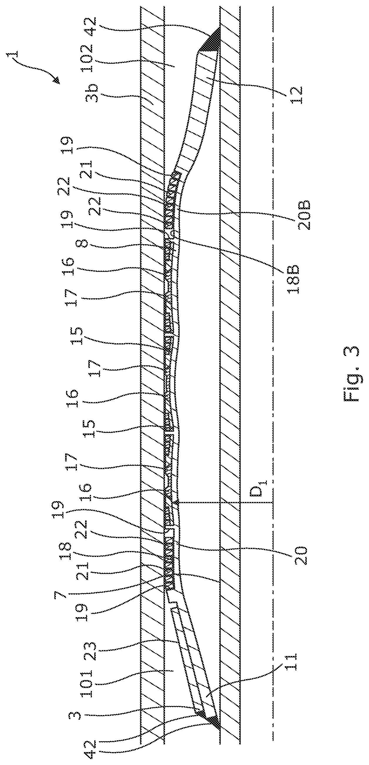
[0096] FIG. 3 shows a cross-sectional view of the annular barrier of FIG. 2 in an expanded condition,
[0097] FIG. 4 shows a partly cross-sectional view of the annular barrier having a split ring-shaped support element with 11 windings,
[0098] FIG. 5 shows a cross-sectional view of yet another unexpanded annular barrier,
[0099] FIG. 6 shows a cross-sectional view of yet another unexpanded annular barrier,
[0100] FIG. 7 shows a cross-sectional view of yet another unexpanded annular barrier,
[0101] FIG. 8 shows the annular barrier of FIG. 7 in its expanded condition,
[0102] FIG. 9 shows a partly cross-sectional view of the annular barrier having a sealing unit with two split ring-shaped retaining elements abutting the sealing element,
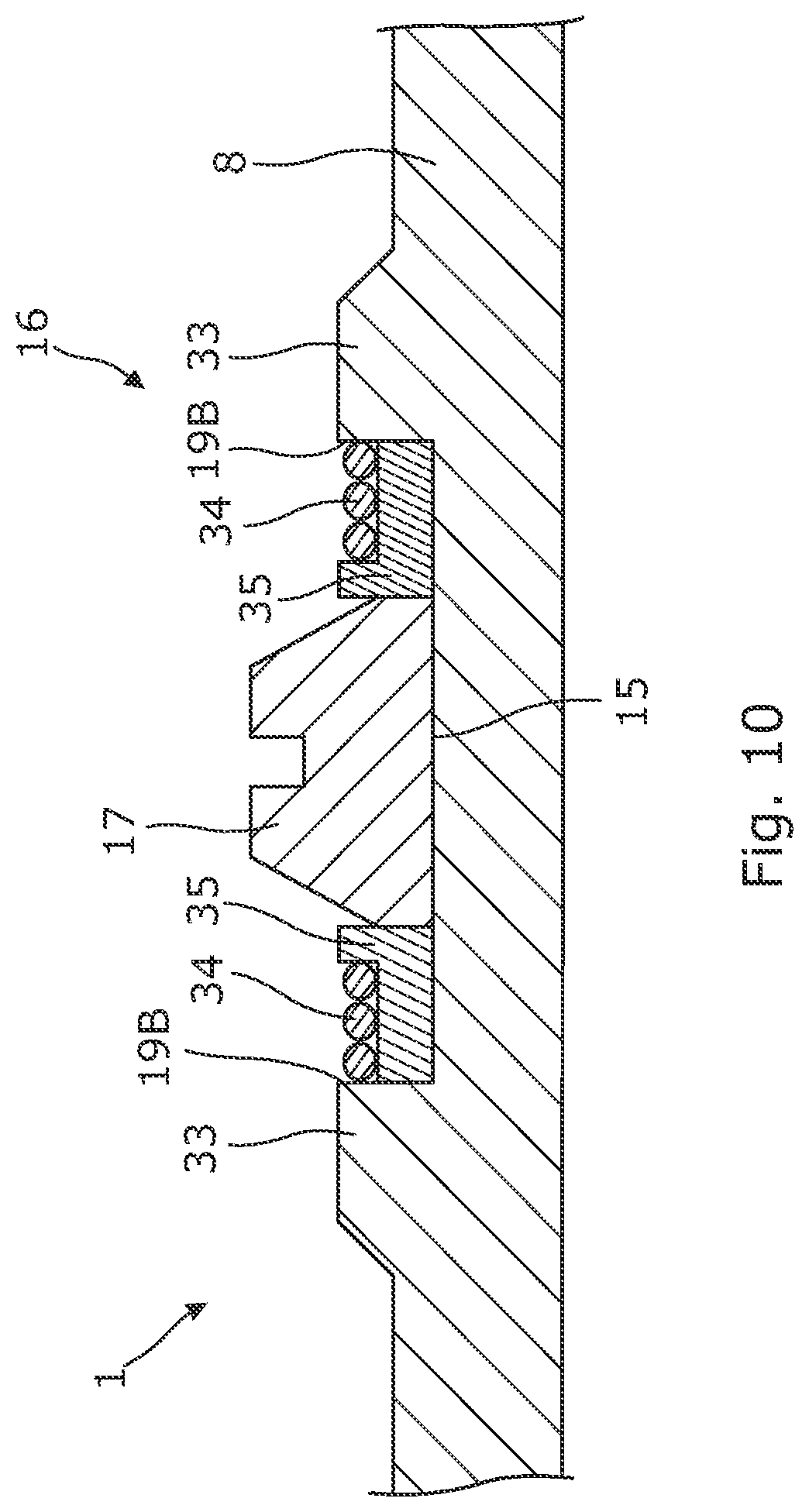
[0103] FIG. 10 shows a partly cross-sectional view of another sealing unit,
[0104] FIG. 11 shows a cross-sectional view of a downhole completion system having several expanded annular barriers,
[0105] FIG. 12 shows in perspective part of another annular barrier having a shear pin assembly and an anti-collapsing unit,
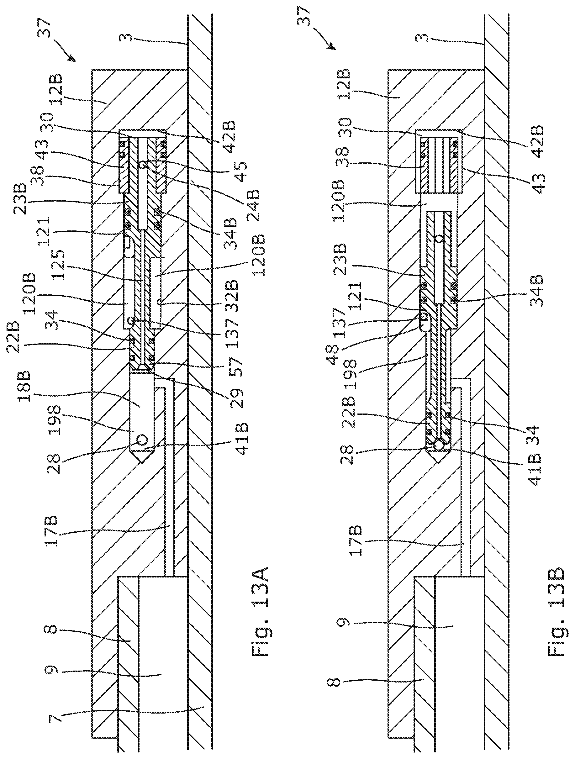
[0106] FIGS. 13A and 13B show a cross-sectional view of part of another annular barrier having a shear pin assembly, the shear pin assembly is shown in a first position in FIG. 13A and in its second closed position in FIG. 13B, and
[0107] FIG. 14 shows a cross-sectional view of an anti-collapse unit.
[0108] All the figures are highly schematic and not necessarily to scale, and they show only those parts which are necessary in order to elucidate the invention, other parts being omitted or merely suggested.
[0109] FIG. 1 shows a cross-sectional view of an annular barrier 1 for providing zonal isolation in an annulus 2 downhole between a well tubular metal structure 3 and a wall 5 of a borehole 4 or another well tubular metal structure 3b, as shown in FIG. 2. The annular barrier comprises a tubular metal part 7 configured to be mounted as part of the well tubular metal structure 3 and an expandable metal tubular 8 surrounding the tubular metal part forming an expandable space 9 therebetween. After the well tubular metal structure has been run in hole, the expandable metal tubular is configured to be expanded in the well downhole from a first outer diameter D.sub.1 to a second outer diameter D.sub.2 (shown in FIG. 3) to abut against the other well tubular metal structure or the wall of the borehole. The expandable metal tubular 8 has a first end 11, a second end 12, an outer face 10 and a longitudinal extension L and comprises a plurality of first circumferential grooves 15 provided in the outer face. A plurality of sealing units 16, each sealing unit comprising a sealing element 17, are arranged in the first circumferential grooves, so that each first circumferential groove comprises one of the sealing units occupying the first circumferential groove along the longitudinal extension. The annular barrier further comprises a second circumferential groove 18 provided between two circumferential edges 19 provided on the outer face and defining a first grooved tubular part 20 of the expandable metal tubular between the circumferential edges 19. The second circumferential groove 18 is arranged closer to the first end of the expandable metal tubular than the first circumferential grooves 15 with the sealing units 16. The annular barrier further comprises a split ring-shaped support element 21, which is arranged in the second circumferential groove for supporting the first grooved tubular part of the expandable metal tubular during expansion. The split ring-shaped support element 21 has a plurality of windings 22, so that when the expandable metal tubular is expanded from the first outer diameter D.sub.1 to the second outer diameter D.sub.2, the split ring-shaped support element 21 partly unwinds and still supports the first grooved tubular part so as to minimise plastic strain in the first grooved tubular part during expansion. As can be seen, the second circumferential groove 18 does not contain a sealing unit nor any sealing elements. Thus, the split ring-shaped support element opposite the first grooved tubular part in the second circumferential groove is not sealing but merely supporting the first grooved part of the expandable metal tubular.
[0110] Thus, by having the split ring-shaped support element opposite the first grooved tubular part plastic strain therein is minimised, and the collapse rating of the annular barrier is thereby increased while keeping a relatively low expansion pressure without having to increase the thickness of the expandable metal tubular. In order to maintain a low expansion pressure, the ends of the expandable metal tubular cannot extend all the way to the beginning of the sealing units since in order to make the thick ends bend, a higher expansion pressure would be needed. Thus, the transition between the sealing units and the thick ends need to be relatively thin in order to bend and bridge between the thicker ends and the thinner areas opposite the sealing units. Furthermore, if there were no split ring-shaped support element supporting the first groove tubular part, the thin first grooved tubular part would just bend radially outwards between the projections 33, thus weakening the first groove tubular part significantly so that the expandable metal tubular could not withstand as high a differential pressure. However, making the first grooved tubular part thicker would increase the expansion pressure. The split ring-shaped support element thus makes it possible to expand the expandable metal tubular with a relatively low expansion pressure around 400 bar and maintain a high collapse rating i.e. withstanding 700 bar differential pressure across the expandable metal tubular.
[0111] As can be seen in FIG. 1, the split ring-shaped support element occupies the second circumferential groove 18 along the longitudinal extension L in the unexpanded condition of the expandable metal tubular 8. Thus, the split ring-shaped support element has a length Ls along the longitudinal extension L in the unexpanded condition corresponding to a length Lg of the second circumferential groove. The split ring-shaped support element is a monolithic split ring-shaped support element. The windings 22 of the split ring-shaped support element abut the circumferential edges 19 of the groove 18, as shown in FIG. 4, and each winding 22 of the split ring-shaped support element 8 abuts each other. After expansion, as shown in FIG. 3, the groove 18 in the expandable metal tubular 8 has increased in length and the split ring-shaped support element 21 has partly unwinded and does no longer fill the groove. During expansion, the split ring-shaped support element supports the first grooved tubular part of the expandable metal tubular, and part of the split ring-shaped support element may after expansion be squeezed in between the other well tubular metal structure 3b and the first grooved tubular part of the expandable metal tubular 8. When the expandable metal tubular is later exposed to a high pressure in the annulus, i.e. a high differential pressure across the expandable metal tubular, the first grooved tubular part has its largest possible strength in the expanded condition and therefore is able to withstand the high pressure without collapsing, i.e. the collapse rating. If the split ring-shaped support element did not have substantially the same length as that of the second circumferential groove, the split ring-shaped support element cannot support the thinner grooved tubular part of the expandable metal tubular during expansion as efficient as when the split ring-shaped support element has substantially the same length. The same applies if the second circumferential groove comprises a sealing element occupying part of the groove along the length, then the split ring-shaped support element cannot support the thinner grooved tubular part of the expandable metal tubular during expansion as efficient as when the split ring-shaped support element has substantially the same length.
[0112] Thus, the split ring-shaped support element may be a monolithic split ring-shaped support element, such as a monolithic split ring/one split ring having more than one winding.
[0113] The annular barrier 1 further comprises a third circumferential groove 18B near the second end. The third circumferential groove 18B is in the same way as the second circumferential groove 18 provided between two circumferential edges 19 provided on the outer face and defining a second grooved tubular part 20B of the expandable metal tubular between the circumferential edges. The third circumferential groove 18B is closer to the second end than the first circumferential grooves with the sealing units, and the third circumferential groove comprises another split ring-shaped support element 21 having a plurality of windings 22, so that when the expandable metal tubular is expanded from the first outer diameter D.sub.1 to the second outer diameter D.sub.2, the split ring-shaped support element 21 partly unwinds. The split ring-shaped support element is arranged in the third circumferential groove for supporting the second grooved tubular part of the expandable metal tubular during expansion, so as to minimise plastic strain in the second grooved tubular part during expansion in the same way as for the first grooved tubular part.
[0114] In order to unwind during expansion, the split ring-shaped support element may be made of a metallic material, such as spring material, and like a helically coiled spring flex along the circumference. The split ring-shaped support element is preferably made of a material having a yield strength of at least 70 MPa, preferably at least 100 MPa, more preferably at least 200 MPa. The ring-shaped support element is preferably one monolithic split ring but may also be divided into two matching helically wounded rings.
[0115] The annular barrier 1 may have just one split ring-shaped support element arranged at the first end of the expandable metal tubular in the event that the annular barrier is only exposed to the high differential pressure from the first zone 101 and not the second zone 102 after expansion of the annular barrier. Thus, the annular barrier 1 does not need to have a split ring-shaped support element in the second circumferential groove 18 as shown in FIG. 6.
[0116] In FIGS. 1-3 and 5-6, the annular barrier further comprises an end sleeve 23 at the first end of the expandable metal tubular. The end sleeve 23 surrounds the expandable metal tubular in order to increase the collapse rating and is welded onto the outer face of the expandable metal tubular 8. The end sleeve 23 is made of a metal material having a higher yield strength than that of the expandable metal tubular. In a preferred embodiment, the end sleeve has a yield strength being twice as high as the yield strength of the expandable metal tubular. In another embodiment, the expandable metal tubular may at the second end further comprise another end sleeve surrounding the expandable metal tubular in order to hinder free expansion of the second end and thus minimise the stress strain of the metal. As can be seen in FIG. 3, the first end having the end sleeve 23 has a straighter curve than the second end, not comprising such end sleeve 23. The first end of the expandable metal tubular is thus prevented from free expansion and the end sleeve 23 having the higher yield strength forces the first end to straighten out, thereby decreasing the stress strain in the first end of the expandable metal tubular. The annular barrier may only have one end sleeve 23 at the first end in the event that the annular barrier is only exposed to the high differential pressure from the first zone 101 and not from the second zone 102 after expansion of the annular barrier.
[0117] In FIG. 1, the first end and the second end of the expandable metal tubular are welded onto the outer face of the tubular metal part 7. The annular barrier has three sealing elements but may have several more. The sealing element 17 is made of elastomer, rubber or similar. In FIG. 2, each of the plurality of sealing units comprises both the sealing element 17 and a split ring-shaped retaining element 31 arranged in the first circumferential grooves 15, and the split ring-shaped retaining element forms a back-up for the sealing element. The split ring-shaped retaining element has more than one winding so that when the expandable metal tubular is expanded from the first outer diameter D.sub.1 to the second outer diameter D.sub.2, the split ring-shaped retaining element partly unwinds but still abuts the sealing element 17. Hereby, it is obtained that the split ring-shaped retaining element ensures that the sealing element is maintained in the longitudinal extension of the expandable metal tubular even when it is being expanded, so that the sealing element retains its intended position and the sealing properties of the expandable metal tubular are enhanced. The sealing element may withstand a higher pressure on the side where the split ring-shaped retaining element is positioned, since the split ring-shaped retaining element functions as a back-up and support system for the sealing element.
[0118] As can be seen in FIG. 3, the ends of the expandable metal tubular have a thickness t.sub.e greater than the thickness t.sub.g (shown in FIG. 1) of the first and/or second grooved tubular part of the expandable metal tubular. By having the split ring-shaped support element opposite the first and/or second grooved tubular part, the grooved tubular part is able to bridge between the ends of the expandable metal tubular having the larger thickness and smaller outer diameter and the part of the expandable metal tubular having the largest outer diameter in the expanded condition. Furthermore, the grooved tubular part partly conforms to the other well tubular metal structure and thus provides that the sealing units are arranged on a substantially straight part of the expandable metal tubular which forms the best basis for a perfect seal. The split ring-shaped support element may have at least 6 windings, preferably at least 10 windings as shown in FIG. 3. In FIG. 2, an intermediate element 31 is arranged between the split ring-shaped support element and the grooved tubular part. The intermediate element is made of polytetrafluoroethylene (PTFE) or polymer.
[0119] In FIGS. 5 and 7, the annular barrier further comprises a tubular metal element 24 connecting the expandable metal tubular 8 with the tubular metal part 7. The tubular metal part is mounted as part of the well tubular metal structure by means of threaded connections 40. The tubular metal element 24 has an extension L in the longitudinal extension and a first end part 25 connected with the tubular metal part 7 and a second end part 26 connected with the expandable metal tubular 8. The first end part is arranged closer to the sealing units 16 along the longitudinal extension of the tubular metal part 7 than the second end part 26. By having a tubular metal element 24 connecting the expandable metal tubular with the tubular metal part 7, where the first end part 25 of the tubular metal element 24 is connected with the tubular metal part and the second end part 26 is connected with the expandable metal tubular, the expandable metal tubular can be expanded without substantially thinning, as shown in FIG. 8. This is due to the fact that the tubular metal element 24 is flexing, hence providing the sleeve with an additional flexing ability. If the expandable metal tubular 8 was only bent at its ends, the bend would unbend which would generate an extremely high stress in the connection between the expandable metal tubular and the tubular metal part which may result in a crack in the connection to the tubular metal part and hence a leaking annular barrier. By having the tubular metal element 24 fastened so that the first end part is arranged closer to the sealing units along the longitudinal extension of the tubular metal part than the second end part, the tubular metal element seeks to keep the angle between the tubular metal element and the tubular metal part at a minimum during expansion of the annular barrier. The tubular metal element is made as a separate element, and subsequently the first end part is connected to the tubular metal part and the second end part is connected to the expandable metal tubular. The tubular metal element is without bends in an unexpanded condition of the annular barrier and bends during expansion. The first end part 25 of the tubular metal element 24 is welded forming a welded connection 42 to the tubular metal part and the second end part 25 of the tubular metal element is welded to the expandable metal tubular 7.
[0120] The tubular metal part has an opening 28 fluidly connected with the expandable space for letting fluid from within the tubular metal part to the expandable space to expand the expandable metal tubular. The opening may be arranged opposite the space 9, as shown in FIGS. 7 and 8, or be arranged near one of the ends of the expandable metal tubular 8 and connected with the expandable space via a valve system. The valve system comprises a valve for shifting between fluid communication between the space and the opening and fluid communication between the space and the annulus for equalising the pressure there between after expansion.
[0121] The split ring-shaped retaining element 34 is preferably made of metal material having a yield strength of at least 70 MPa, preferably at least 100 MPa, more preferably at least 200 MPa. The split ring-shaped retaining element 34 is made of a spring material and unwinds by less than one winding when the expandable metal tubular 8 is expanded from the first outer diameter D.sub.1 to the second outer diameter D.sub.2. As shown in FIG. 9, the split ring-shaped retaining element 34 has a width w in the longitudinal extension, the width being substantially the same in the first outer diameter D.sub.1 and the second outer diameter D.sub.2 of the expandable metal tubular. The sealing unit 16 has two split ring-shaped retaining elements 34 which together with the sealing element 17 fill the first circumferential groove 15 from edge 19B to edge 19B at the projections 33. The split ring-shaped retaining element 34 has a plurality of windings and in FIG. 9, the split ring-shaped retaining element 34 has three windings. The expandable metal tubular 8 has a first thickness T.sub.1 in the first circumferential groove between a first and a second circumferential edges 19B at the projections 33 and a second thickness T.sub.2 in the adjacent areas, where the first thickness T.sub.1 being smaller than the second thickness T.sub.2. Hereby, it is obtained that expansion of the expandable metal tubular is facilitated in the first circumferential groove so that the expandable metal tubular may expand more in this area than in the adjacent areas, whereby the sealing element may be further forced against the inner face of the other well tubular metal structure or borehole.
[0122] The circumferential edges 19, 19B are extending in a radial extension in relation to the expandable metal tubular, where radial extension being perpendicular to the longitudinal extension L of the expandable metal tubular. The grooves are thus provided between projections 33 of the expandable metal tubular.
[0123] In FIG. 10, an intermediate element 35 is arranged between the split ring-shaped retaining element 34 and the sealing element 17. The intermediate element is made of polytetrafluoroethylene (PTFE) or polymer. The split ring-shaped retaining element 34 and the intermediate element 35 are arranged in an abutting manner to the sealing element, so that at least one of the split ring-shaped retaining element and the intermediate element abut the sealing element. The sealing element is made of an elastomer, rubber, polytetrafluoroethylene (PTFE) or another polymer. The intermediate element 35 may be made of a flexible material and is adapted to maintain the split ring-shaped retaining element 34 in position and functions as protection and support of the sealing element 17. The split ring-shaped retaining element 34, the intermediate element 32 and the sealing element 17 are placed in the groove 15 between the first and second circumferential edges 19B. In this embodiment, the windings of the split ring-shaped retaining elements 34 have a round cross-section and partly overlap the intermediate elements 35.
[0124] Thus, when the expandable metal tubular is expanded by 30%, the split ring-shaped retaining element 7 is unwound by approximately 30% of the circumference of the split ring-shaped retaining element 7, and thus the split ring-shaped retaining element 7 decreases its number of windings so that it is still capable of closing the gaps in the longitudinal extension, whereby the sealing element, the split ring-shaped retaining elements and the intermediate elements (if present) fill out the gap between the first and second circumferential edges 3, 4.
[0125] Even though not shown, the split ring-shaped support element 21 may have a round cross-section. In addition, the split ring-shaped support element in one groove may be comprised of several separate parts, where each part has a plurality of windings. By being comprised of several parts, the split ring-shaped support element can more easily and quickly unwind without limiting the support effect and without increasing the plastic strain of the expandable metal tubular.
[0126] In FIG. 11, the downhole completion 100 comprises the well tubular metal structure 3 and the annular barrier 1, where the tubular metal part of the annular barriers is mounted as part of the well tubular metal structure.
[0127] In FIG. 12, the annular barrier 1 further comprises a shear pin assembly 37 fluidly connecting the opening 28 in the tubular metal part 7 and the expandable space 9 in order to allow expansion fluid within the well tubular metal structure 3 to expand the expandable metal tubular 8. The shear pin assembly 37 has a first position (shown in FIG. 13A) in which expansion fluid is allowed to flow into the space 9 and a second position (shown in FIG. 13B) in which the opening 28 is blocked, preventing expansion fluid from entering the space 9. As shown in FIG. 12, the annular barrier 1 further comprises an anti-collapsing unit 111 comprising an element 201 (as shown in FIG. 14) movable at least between a first position and a second position. The anti-collapsing unit has a first inlet 25B which is in fluid communication with the first zone, and a second inlet 26B which is in fluid communication with the second zone, and the anti-collapsing unit having an outlet 27 which is in fluid communication with the space 9. In the first position, the first inlet is in fluid communication with the outlet, equalising the first pressure of the first zone 101 with the space pressure in the space 9, and in the second position, the second inlet is in fluid communication with the outlet, equalising the second pressure of the second zone with the space pressure.
[0128] As shown in FIG. 12, the shear pin assembly 37 has a port A receiving fluid from an inside of the well tubular structure 3 through the screen 44. The port A is fluidly connected with a port D during expansion, causing the expansion fluid within the well tubular metal structure 3 to expand the expandable metal tubular 8. When the expandable metal tubular 8 is expanded to abut the wall of the tubular metal structure, the pressure builds up and a shear pin 24B (arranged in opening 45 in FIG. 13A) or disc (in the fluid channel 125) within the shear pin assembly shears closing the fluid connection from port A and the opening 28 (as shown in FIG. 13B) and opening the fluid connection between a port B (in fluid communication with the outlet 27) and a port C (in fluid communication with the space 9), so that fluid from the second inlet 26B can be let into the space 9 through the shear pin assembly i.e. between opening 137 and channel 27B. When the first pressure increases in the first zone, fluid from a port E connected with a port I, being the first inlet 25B, presses the element 201 (shown in FIG. 14) to move so that fluid communication is provided between port I and a port H, being the outlet, and thus further through ports B and C and into the space 9 through port D. When the second pressure increases in the second zone, the element is forced in the opposite direction, and fluid communication between port G (in fluid communication with the second zone through port F) and port H is provided, i.e. fluid communication between the second inlet 26B and the outlet 27 of the anti-collapsing unit 111, and thus fluid is let into the annular space through ports B, C and D.
[0129] The shear pin assembly shown in FIGS. 13A and 13B comprises a first bore part 198 having a first inner diameter and a second bore part 120B having an inner diameter which is larger than that of the first bore part. The opening 28 and a second opening 17B are arranged in the first bore part 19B and are displaced along the bore extension. The annular barrier 1 further comprises a piston 121 arranged in the bore 18B, the piston comprising a first piston part 22B having an outer diameter substantially corresponding to the inner diameter of the first bore part 19B, and comprising a second piston part 23B having an outer diameter substantially corresponding to the inner diameter of the second bore part 120B. The annular barrier 1 further comprises a rupture element 24B preventing movement of the piston 121 until a predetermined pressure in the bore 18B is reached. The strength of the rupture element is set based on a predetermined pressure acting on the areas of the ends of the piston, and thus, the difference in outer diameters results in a movement of the piston when the pressure exceeds the predetermined pressure. The piston 121 comprises a fluid channel 125 being a through bore providing fluid communication between the first and second bore parts 19B, 120B.
[0130] In FIGS. 13A and 13B, the rupture element 24B is a shear pin but may also be a disc. In FIG. 13A, the shear pin 24B is intact and extends through the piston and the inserts 43, and in FIG. 13B, the shear pin is sheared and the piston is allowed to move, and the inserts 43 have moved towards the centre of the bore 18B. Depending on the isolation solution required to provide isolation downhole, the rupture element 24B is selected based on the expansion pressure so as to break at a pressure higher than the expansion pressure but lower than the pressure rupturing the expandable metal tubular or jeopardising the function of other completion components downhole. The bore 18B and the piston 121 may be arranged in a connection part connecting the first ends to the tubular metal part.
[0131] In FIG. 13A, the annular barrier 1 comprises a locking element 38 which is arranged around the second piston part 23B. The bore further comprises a third opening 137 in the second bore part 120B, which the third opening is in fluid communication with the space 9 and the annulus/borehole 2. The third opening 137 may be arranged in fluid communication with a shuttle valve, as shown in FIG. 14, in such a way that the shuttle valve is arranged between the third opening and the annulus, thus providing fluid communication between the space 9 and the annulus. The shuttle valve provides, in a first position, fluid communication between the space 9 and the first zone 101 of the annulus, and in a second position, the shuttle valve provides fluid communication between the annular space and the second zone 102 of the annulus.
[0132] The expandable metal tubular may be made from one tubular metal blank, wherein the blank may be made by centrifugal casting or spin casting. Furthermore, the first and second circumferential edges 19 may be provided by machining the blank.
[0133] FIG. 11 shows a cross-sectional view of annular barriers 1 which have been expanded in an annulus 2 between the well tubular structure 3 and an inside face of the borehole 4. The annular barrier 1 provides zone isolation between a first zone 101 and a second zone 102 of the borehole. The annular barrier 1 has a longitudinal extension which coincides with the longitudinal extension of the casing/well tubular structure 3. The annular barrier 1 comprises a tubular metal part 7 which may be a separate tubular part or a casing part for mounting a part of the well tubular structure 3. Furthermore, the annular barrier 1 comprises the expandable metal tubular 1 which surrounds the tubular metal part, and each end of the expandable metal tubular 1 may be connected with the tubular metal part by means of connection parts. The expandable metal tubular 1 and the tubular metal part 7 enclose an annular barrier space 9, and an expansion opening 28 is provided in the tubular metal part, through which fluid may enter the space 9 in order to expand the expandable metal tubular 1 as shown in FIGS. 3 and 8. The expandable metal tubular 1 is expanded until the sealing elements 16 or the projections 33 abut the inner face of the borehole 4, so that fluid is prevented from flowing freely from the first zone 101 to the second zone 102.
[0134] As shown in FIG. 11, two annular barriers 1 are often used to isolate a production zone 400. A fracturing valve or inflow valve section 120, also called the frac port or inflow/production valve, is arranged in between the annular barriers 1, so that when the annular barriers 1 have been expanded, the frac port or valve 120 is opened and fluid is let into the formation for creating fractures in the formation to ease the flow of hydrocarbon-containing fluid, such as oil, into the well tubular structure 3. The fracturing valve or inflow section 120 may also comprise an inlet section which may be the same as the frac port. A screen may be arranged so that the fluid is filtered before flowing into the casing.
[0135] The annular barrier further comprises an intermediate sleeve (not shown) arranged in between the expandable metal tubular 1 and the tubular metal part 7. The intermediate sleeve is connected with the tubular metal part 7 and the expandable metal tubular 1, thus dividing the space 9 into a first space section and a second space section. The intermediate sleeve is squeezed in between the tubular metal part and the expandable metal tubular. The intermediate sleeve may also be connected with the tubular metal part in another manner, such as crimped onto the tubular part. In order to equalise the pressure, the expandable metal tubular has an aperture providing fluid communication between the first or the second zone and one of the space sections, thus equalising the pressure between the space and the zone. When e.g. performing hydralic fracturing or another well treatment, the pressure in one of the zones in which hydraulic fracturing is performed is increasing, and in order to prevent the expandable metal tubular from collapsing, the fluid is let in through the aperture and into the first space section. When exposed to the increased pressure, the intermediate sleeve moves towards the tubular metal part, thus yielding to the increased pressure in the first space section, and the first space section increases until the pressure equalises or the intermediate sleeve abuts the tubular metal part.
[0136] The expandable metal tubular part may also be crimped onto the tubular part, or, if the annular barrier comprises a sleeve, crimped onto the sleeve at its ends. The sleeve is flexible and made of metal or a polymer, such as elastomer.
[0137] The tubular blank may be made of any kind of metal, such as iron, steel or stainless steel, or more ductile materials, such as copper, aluminium, lead, tin, nickel, or a combination thereof.
[0138] By fluid or well fluid is meant any kind of fluid that may be present in oil or gas wells downhole, such as natural gas, oil, oil mud, crude oil, water, etc. By gas is meant any kind of gas composition present in a well, completion, or open hole, and by oil is meant any kind of oil composition, such as crude oil, an oil-containing fluid, etc. Gas, oil, and water fluids may thus all comprise other elements or substances than gas, oil, and/or water, respectively.
[0139] By a casing or well tubular metal structure is meant any kind of pipe, tubing, tubular, liner, string etc. used downhole in relation to oil or natural gas production.
[0140] Although the invention has been described in the above in connection with preferred embodiments of the invention, it will be evident for a person skilled in the art that several modifications are conceivable without departing from the invention as defined by the following claims.
* * * * *
D00000
D00001
D00002
D00003
D00004
D00005
D00006
D00007
D00008
D00009
D00010
D00011
XML
uspto.report is an independent third-party trademark research tool that is not affiliated, endorsed, or sponsored by the United States Patent and Trademark Office (USPTO) or any other governmental organization. The information provided by uspto.report is based on publicly available data at the time of writing and is intended for informational purposes only.
While we strive to provide accurate and up-to-date information, we do not guarantee the accuracy, completeness, reliability, or suitability of the information displayed on this site. The use of this site is at your own risk. Any reliance you place on such information is therefore strictly at your own risk.
All official trademark data, including owner information, should be verified by visiting the official USPTO website at www.uspto.gov. This site is not intended to replace professional legal advice and should not be used as a substitute for consulting with a legal professional who is knowledgeable about trademark law.