Small Hydraulic Excavator
TAKEBAYASHI; Yoshifumi ; et al.
U.S. patent application number 16/080387 was filed with the patent office on 2020-05-28 for small hydraulic excavator. The applicant listed for this patent is Hitachi Construction Machinery Tierra Co., Ltd.. Invention is credited to Taihei MAEHARA, Kazushige MORI, Natsuki NAKAMURA, Yoshifumi TAKEBAYASHI, Hajime YOSHIDA.
| Application Number | 20200165794 16/080387 |
| Document ID | / |
| Family ID | 60116773 |
| Filed Date | 2020-05-28 |

| United States Patent Application | 20200165794 |
| Kind Code | A1 |
| TAKEBAYASHI; Yoshifumi ; et al. | May 28, 2020 |
Small Hydraulic Excavator
Abstract
To provide a small hydraulic excavator, which even may have an upperstructure formed such that at least its rear end swings within a body width range and having a limited installation space for devices, that allows an accumulator to be disposed and allows the accumulator to be protected from external force generated during work. The present invention relates to a rear small-swing type mini excavator that includes an accumulator 30 accommodating and recovering potential energy and hydraulic energy used by at least one of drives of an undercarriage 1, an upperstructure 2 formed such that its rear end swings within the body width range of the undercarriage 1, and a working device 3. In the rear small-swing type mini excavator, the accumulator 30 is disposed between a valve block 26 and a front longitudinal board 41 of a longitudinal board member included in a main frame 10 along the front longitudinal board 41, and a pipe connected to the accumulator 30 and the valve block 26 is disposed closer to the accumulator 30 and the valve block 26.
| Inventors: | TAKEBAYASHI; Yoshifumi; (Kouka, Shiga, JP) ; YOSHIDA; Hajime; (Oumihachiman, Shiga, JP) ; MORI; Kazushige; (Moriyama, Shiga, JP) ; NAKAMURA; Natsuki; (Kouka, Shiga, JP) ; MAEHARA; Taihei; (Kouka, Shiga, JP) | ||||||||||
| Applicant: |
|
||||||||||
|---|---|---|---|---|---|---|---|---|---|---|---|
| Family ID: | 60116773 | ||||||||||
| Appl. No.: | 16/080387 | ||||||||||
| Filed: | February 22, 2017 | ||||||||||
| PCT Filed: | February 22, 2017 | ||||||||||
| PCT NO: | PCT/JP2017/006681 | ||||||||||
| 371 Date: | August 28, 2018 |
| Current U.S. Class: | 1/1 |
| Current CPC Class: | E02F 9/18 20130101; E02F 9/2217 20130101; E02F 9/16 20130101; E02F 9/2267 20130101; E02F 9/0866 20130101; E02F 9/121 20130101; E02F 3/964 20130101; E02F 9/0875 20130101; E02F 9/2275 20130101; E02F 3/325 20130101 |
| International Class: | E02F 3/32 20060101 E02F003/32; E02F 9/18 20060101 E02F009/18; E02F 9/08 20060101 E02F009/08; E02F 9/22 20060101 E02F009/22; E02F 9/16 20060101 E02F009/16; E02F 9/12 20060101 E02F009/12 |
Foreign Application Data
| Date | Code | Application Number |
|---|---|---|
| Apr 20, 2016 | JP | 2016-084774 |
Claims
1. A small hydraulic excavator comprising: an undercarriage; an upperstructure that is disposed on the undercarriage and is formed such that a rear end is swingable within a body width range of the undercarriage; a main frame of the upperstructure that has a pair of longitudinal board members juxtaposed along a longitudinal direction of the upperstructure; a working device that is vertically rotatably supported in front of a center of swing of the upperstructure and includes a boom and a boom cylinder; a counterweight that is disposed on a rear end side of the upperstructure; a valve block that is disposed on a side of the pair of longitudinal board members of the main frame and includes at least a plurality of directional control valves; and an accumulator that accommodates and recovers potential energy and hydraulic energy used by at least one of drives of the undercarriage, the upperstructure, and the working device, the small hydraulic excavator in which a frame continuous with a floor seat provided on the upperstructure and having an operator seat and the counterweight serve as a partition wall that forms an engine room, wherein the accumulator is disposed between the valve block and the longitudinal board member of the main frame along the longitudinal board member, and a pipe connected to the accumulator and the valve block is disposed closer to the accumulator and the valve block.
2. The small hydraulic excavator according to claim 1, comprising a retention unit that is installed to the main frame and retains the accumulator.
3. The small hydraulic excavator according to claim 1, wherein the accumulator and the valve block are disposed underneath the floor seat.
4. The small hydraulic excavator according to claim 1, wherein the main frame includes a transverse board disposed on a rear end side of the upperstructure and connected to the pair of longitudinal board members, and another accumulator different from the accumulator is disposed along the transverse board.
Description
TECHNICAL FIELD
[0001] The present invention relates to a small hydraulic excavator equipped with an accumulator that accumulates potential energy and hydraulic energy and recovers the energies.
BACKGROUND ART
[0002] Patent literatures 1 and 2 describe a technique of reducing energy consumption by regenerating potential energy and hydraulic energy generated by an inertial load in a hydraulic driving circuit and utilizing the potential energy and the hydraulic energy. Patent literatures 1 and 2 further describe one or a plurality of accumulators that accumulate potential energy and hydraulic energy and recover the energies.
[0003] Patent literature 3 describes a technique relating to arrangement of accumulators. Patent literature 3 describes a mid-size hydraulic excavator that arranges accumulators inside the counterweight.
CITATION LIST
Patent Literature
PATENT LITERATURE 1: JP-T No. 2015-501913
PATENT LITERATURE 2: JP-A No. 2015-90194
PATENT LITERATURE 3: JP-A No. 2015-59330
SUMMARY OF INVENTION
Technical Problem
[0004] Even a small hydraulic excavator, such as a rear small-swing type mini excavator with an upperstructure having its rear end swing within a body width range of the undercarriage and a micro-swing type mini excavator, needs to be equipped with an accumulator for a further reduction in energy consumption. A small hydraulic excavator such as the above-described mini excavators, however, is configured such that the rear end of the upperstructure swings within the body width range, and the upperstructure is therefore compactly constructed. An operator seat covered by a canopy is disposed on the upperstructure of the mini excavator. An operating device for operating the undercarriage is disposed in front of the operator seat. Operating devices for operating various actuators that actuate the upperstructure and a working device are disposed at both sides of the operator seat. Furthermore, a floor seat that forms a seating unit of the operator seat is provided on the upperstructure in a manner extending backward from a lower position in front of the operator seat and standing in the middle. An engine room accommodating an engine and a hydraulic pump is provided underneath the seating unit of the operator seat on the upperstructure. A laterally arcuately extending convexly curved counterweight is provided on the rear end side of the upperstructure in a manner covering the rear portion of the engine room. Furthermore, various devices such as a fuel tank, a hydraulic oil tank, and a control valve are disposed on the upperstructure. When disposing devices including an engine on the upperstructure, only a small space is therefore allowed for the devices because of the compact size of the upperstructure as described above.
[0005] Patent literature 3 describes a mid-size hydraulic excavator having a large counterweight, and this conventional technique allows accumulators to be disposed inside the counterweight. Disposing an accumulator inside the counterweight of a small hydraulic excavator such as the above-described mini excavator, however, needs an increase in the size of the counterweight to secure a determined weight of the counterweight. A small hydraulic excavator such as a mini excavator generally needs to be compactly constructed considering use, for example, on a narrow pathway, and the technique of Patent literature 3 is therefore inapplicable to the counterweight of such a small hydraulic excavator. Furthermore, an accumulator needs to be installed considering that the accumulator may take a large impact during work such as excavation work. A small hydraulic excavator such as a mini excavator therefore needs to arrange an accumulator in consideration of protection from external force.
[0006] To overcome the above-described problems, the present invention aims to provide a small hydraulic excavator, which even may include an upperstructure configured to have at least its rear end swing within the body width range and having a limited installation space for devices, that allows an accumulator to be disposed and further allows the accumulator to be protected from external force generated during work.
Solution to Problem
[0007] To overcome the above-described problems, a small hydraulic excavator according to the present invention includes an undercarriage, an upperstructure that is disposed on the undercarriage and is formed such that a rear end is swingable within a body width range of the undercarriage, a main frame of the upperstructure that has a pair of longitudinal board members juxtaposed along a longitudinal direction of the upperstructure, a working device that is vertically rotatably supported in front of a center of swing of the upperstructure and includes a boom and a boom cylinder, a counterweight that is disposed on a rear end side of the upperstructure, a valve block that is disposed on a side of the pair of longitudinal board members of the main frame and includes at least a plurality of directional control valves, and an accumulator that accommodates and recovers potential energy and hydraulic energy used by at least one of drives of the undercarriage, the upperstructure, and the working device. In the small hydraulic excavator, a frame continuous with a floor seat provided on the upperstructure and having an operator seat and the counterweight serve as partition walls that form an engine room. The accumulator is disposed between the valve block and the longitudinal board member of the main frame along the longitudinal board member. A pipe connected to the accumulator and the valve block is disposed closer to the accumulator and the valve block.
Advantageous Effects of Invention
[0008] A small hydraulic excavator according to the present invention has an accumulator disposed along a longitudinal board member included in the main frame. This configuration allows the accumulator to be disposed even on an upperstructure that is configured to have its rear end swing within the body width range and has a limited installation space for devices. Furthermore, the accumulator is disposed between the longitudinal board member of the main frame as a strengthening member and a valve block, which can protect the accumulator from external force generated during work such as excavation work. As another advantageous effect, a pipe connected to the accumulator and the valve block is disposed closer to the accumulator and the valve blocks, which allows the pipe to be formed shorter.
BRIEF DESCRIPTION OF DRAWINGS
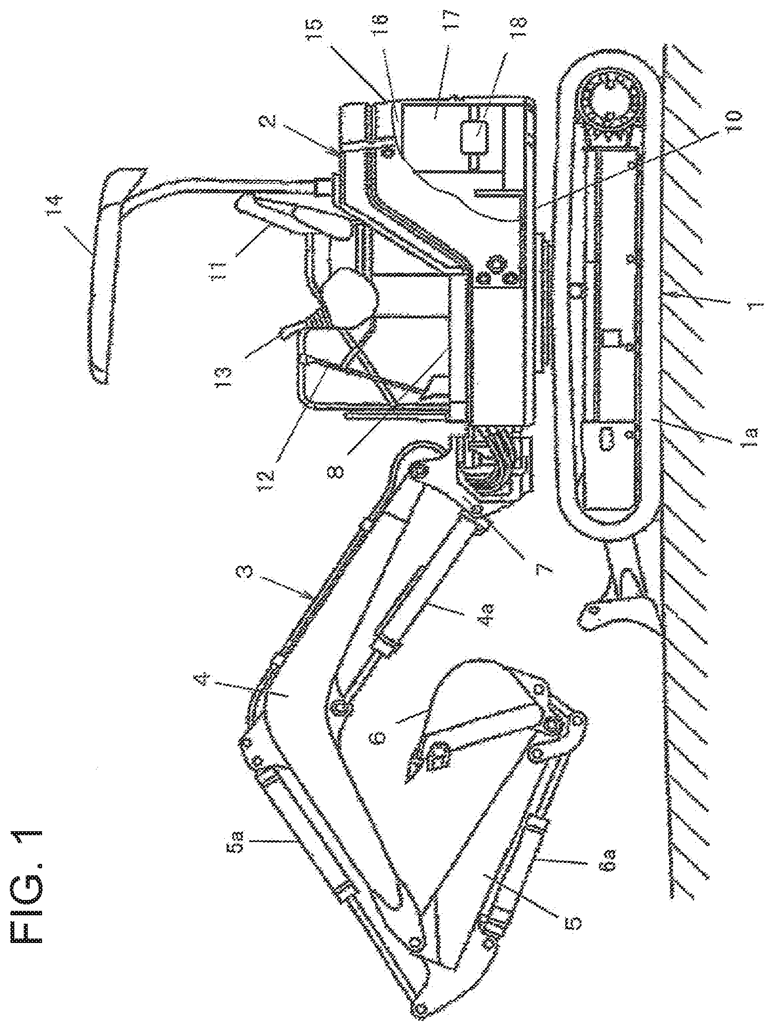
[0009] FIG. 1 is a side view of a mini excavator constituting a first embodiment of a small hydraulic excavator according to the present invention.
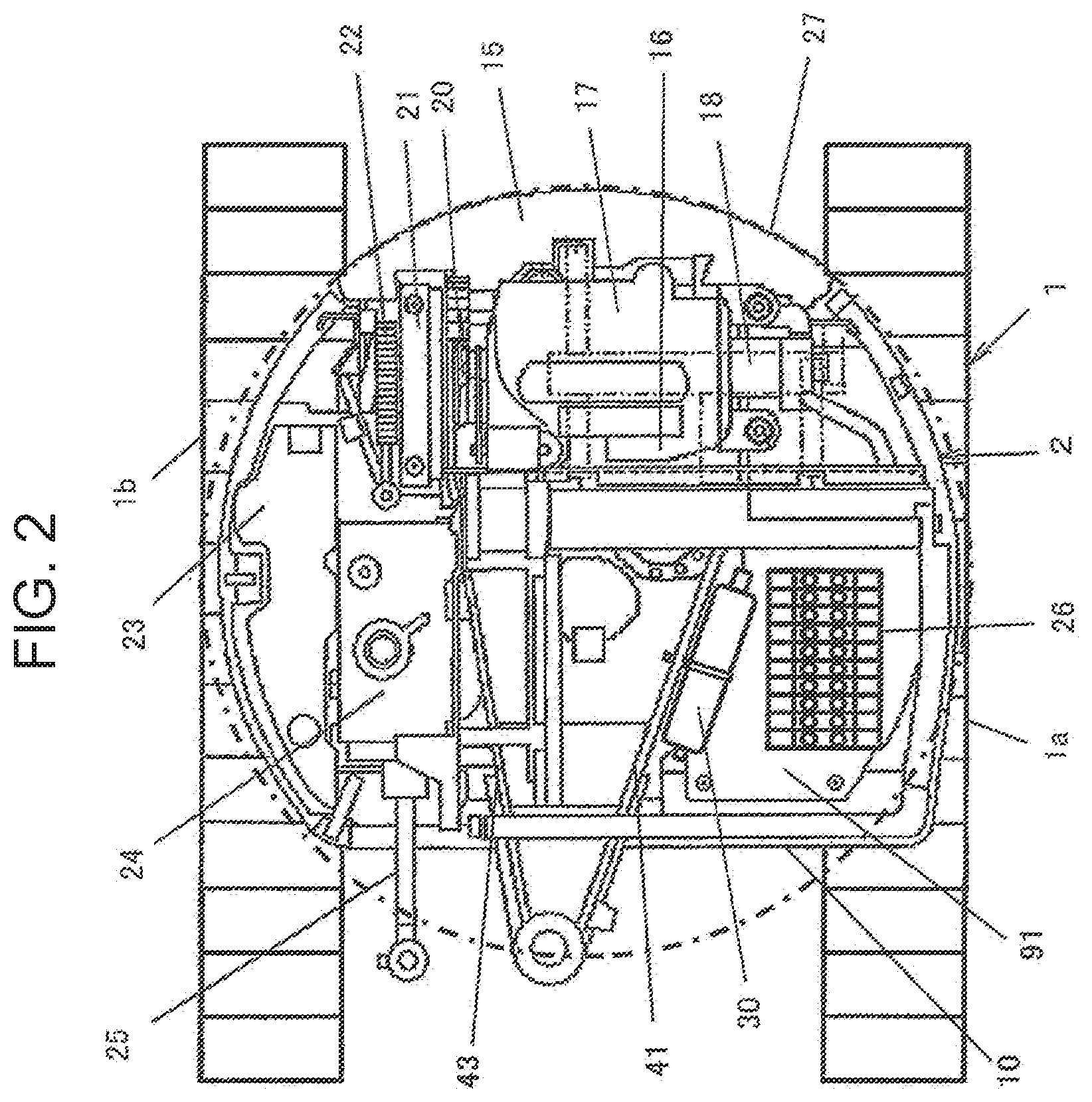
[0010] FIG. 2 is a flat view illustrating arrangement of devices mounted on a main frame of the mini excavator according to the first embodiment.
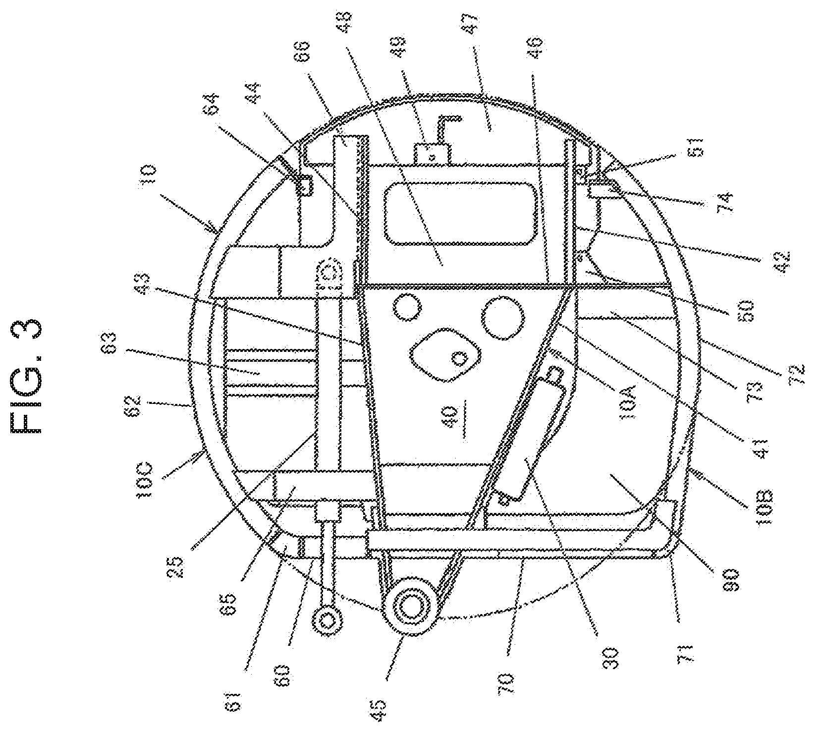
[0011] FIG. 3 is a flat view illustrating a configuration of the main frame included in the first embodiment.
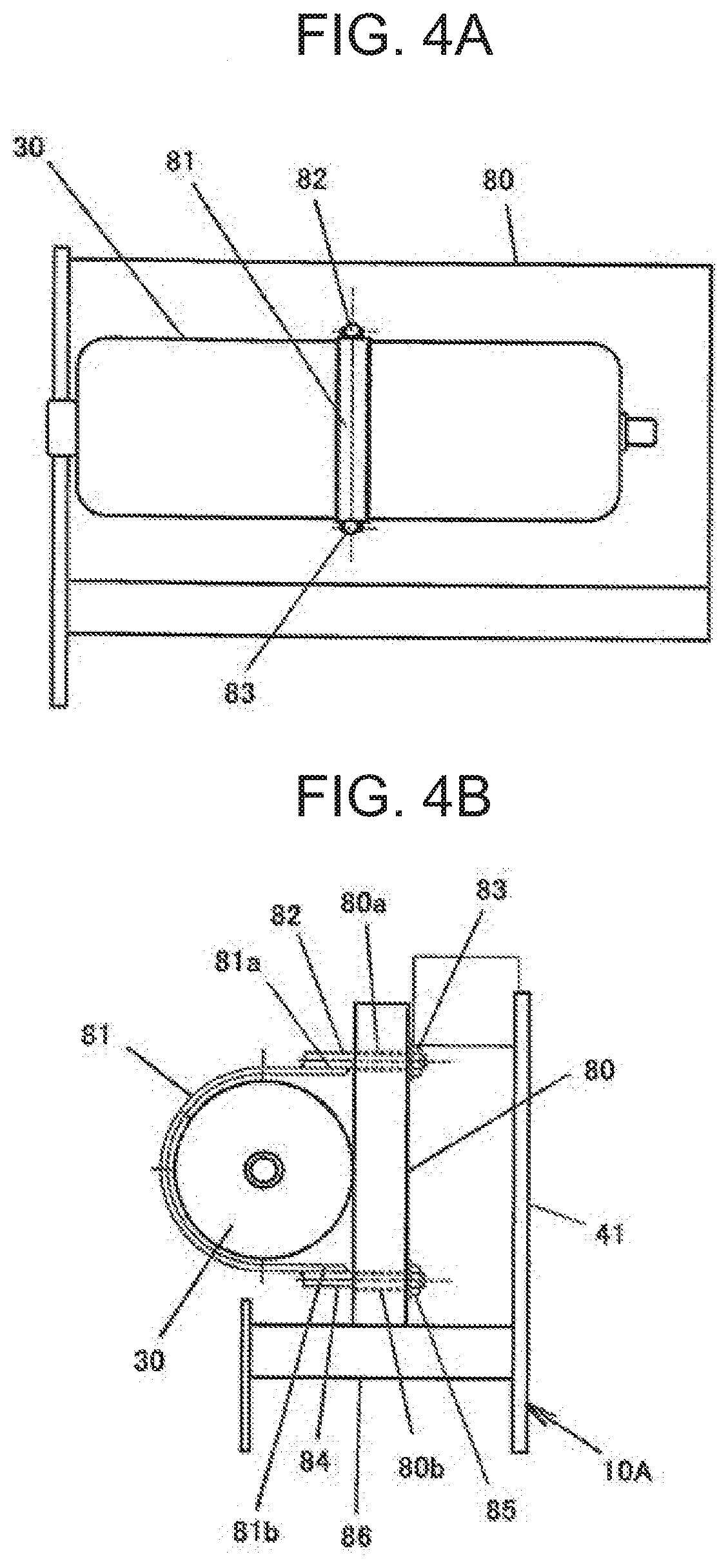
[0012] FIGS. 4A,B are drawings of a retention unit of an accumulator included in the first embodiment. FIG. 4A is a side view, and FIG. 4B is a front view.
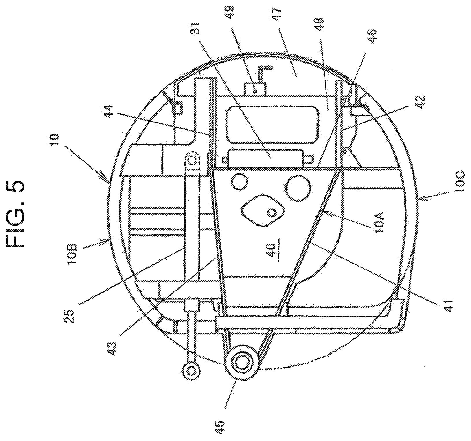
[0013] FIG. 5 is a flat view of a main frame constituting an essential part of a second embodiment of the present invention.
DESCRIPTION OF EMBODIMENTS
[0014] Embodiments of a small hydraulic excavator according to the present invention will now be described with reference to the drawings.
[0015] As illustrated in FIG. 1 and FIG. 2, the first embodiment of a small hydraulic excavator of the present invention is constituted as, for example, a rear small-swing type mini excavator. The first embodiment includes an undercarriage 1 having a pair of tracks 1a and 1b and an upperstructure 2 mounted on the undercarriage 1. The first embodiment further includes a working device 3 for performing work such as excavation of earth and sand.
[0016] The working device 3 is coupled to a swing post 7 disposed on a front end side of the upperstructure 2, situated at a front position with respect to the center of swing of the upperstructure 2, and supported in a laterally swingable and vertically rotatable manner.
[0017] The working device 3 includes a boom 4 coupled to the swing post 7, an arm 5 coupled to the distal end of the boom 4, a bucket 6 coupled to the distal end of the arm 5, and a plurality of hydraulic actuators including a boom cylinder 4a vertically rotating the boom 4, an arm cylinder 5a vertically rotating the arm 5, and a bucket cylinder 6a vertically rotating the bucket 6.
[0018] An operator seat 11 is disposed on a main frame 10 of the upperstructure 2. A floor seat 8 forming a seating unit of the operator seat 11 is provided in a manner extending backward from a position for placing the operator's feet in front of the operator seat 11 and standing in the middle. A pair of operating devices 12 for operating the undercarriage 1 are disposed in front of the operator seat 11, and a pair of operating devices 13 for operating the upperstructure 2 and the working device 3 are disposed at the right and left positions of the operator seat 11. A canopy 14 covering the operator seat 11 from above is further provided.
[0019] A counterweight 15 is disposed on a rear end side on the main frame 10 of the upperstructure 2. An engine room 16 is formed underneath the seating unit of the operator seat 11 on the floor seat 8, on the inner side of the counterweight 15. A frame continuous with the floor seat 8 having the operator seat 11 and the counterweight 15 serve as partition walls that foam the engine room 16. The engine room 16 accommodates therein a hydraulic pump 18 for supplying pressure oil to a plurality of hydraulic actuators such as the earlier-described hydraulic actuator included in the working device 3, a travel motor for driving the undercarriage 1, and a swing motor for driving the upperstructure 2 and an engine 17 for driving the hydraulic pump 18.
[0020] As illustrated in FIG. 2, the engine 17 is transversely mounted. In the engine room 16, a cooling fan 20 starting in response to drive of the engine 17, a radiator 21 and an oil cooler 22 cooled by the wind generated by the cooling fan 20 are disposed at the right-side side part of the engine 17. A fuel tank 23 and a hydraulic oil tank 24 are disposed in front of the radiator 21 and the oil cooler 22 in the engine room 16. A swing cylinder 25 for swinging the boom 4 of the working device 3 is disposed underneath the hydraulic oil tank 24.
[0021] Furthermore, a valve block 26 at least including a plurality of directional control valves for controlling a flow of the pressure oil supplied from the hydraulic pump 18 to the hydraulic actuators and an accumulator 30 that accumulates and recovers potential energy and hydraulic energy used by at least one of hydraulic driving systems of the undercarriage 1, the upperstructure 2, and the working device 3 are disposed in front of the engine room 16, on the main frame 10 on a front underneath side of the earlier-described floor seat 8. The installation modes of the accumulator 30 will be described later.
[0022] As further illustrated in FIG. 2, the counterweight 15 is disposed in a manner covering a rear surface on the rear end side of the engine room 16 and is formed in a laterally arcuately extending convexly curved shape. This rear small-swing type mini excavator according to the first embodiment is configured such that the upperstructure 2 swings with a rear-end surface portion of the upperstructure 2 including the counterweight 15 fit within the body width range of the undercarriage 1 as indicated by a dotted chain line 27.
[0023] As illustrated in FIG. 3, the main frame 10 of the upperstructure 2 is constituted by a center frame 10A, a left side frame 10B disposed at the left side of the center frame 10A, and a right side frame 10C disposed at the right side of the center frame 10A.
[0024] The center frame 10A has a bottom board 40, a left front longitudinal board 41 and a left rear longitudinal board 42 forming one side of a pair of longitudinal board members arranged upright on the bottom board 40 and juxtaposed along the longitudinal direction of the upperstructure 2, and a right front longitudinal board 43 and a right rear longitudinal board 44 forming the other side of the pair of longitudinal board members. The center frame 10A further has a swing bracket 45 joined to the front ends of the bottom board 40 and the front longitudinal boards 41 and 43 and accommodating the earlier-described swing post 7 in a horizontally rotatable manner.
[0025] The center frame 10A further has a transverse board 46 arranged upright on the bottom board 40, joined between the rear ends of the front longitudinal boards 41 and 43 and the front ends of the rear longitudinal boards 42 and 44, and laterally extending. An engine supporting unit 48 and a supporting bracket 49 are provided between the rear longitudinal boards 42 and 44 in a manner separated from each other in the longitudinal direction. Supporting brackets 50 and 51 are provided at the left side of the left rear longitudinal board 42 in a manner separated from each other in the longitudinal direction. The engine 17 is mounted on the engine supporting unit 48 and assembled by using the supporting brackets 49, 50, and 51.
[0026] The right side frame 10C is formed of, for example, a pipe member having a D-shape sectional surface and has a straight front frame 60 joined to the right side of the swing bracket 45 and laterally extending and an arcuately curved frame 62 coupled to an end portion of the front frame 60 through a joint 61. The curved frame 62 has its middle portion coupled to the bottom board 40 through a suspension beam 63 and has its rear end portion coupled to the bottom board 40 through a coupling bracket 64.
[0027] Between the curved frame 62 and the right front longitudinal board 43, an attachment board 65 is joined in front of the suspension beam 63, and an attachment board 66 is joined behind the suspension beam 63. The attachment boards 65 and 66 are provided in consideration of allocation of a space for the swing cylinder 25 and installation of the fuel tank 23, the hydraulic oil tank 24, the radiator 21, and the oil cooler 22.
[0028] As with the right side frame 10C, the left side frame 10B is formed of, for example, a pipe member having a D-shape sectional surface and has a straight front frame 70 joined to the left side of the swing bracket 45 and laterally extending and an arcuately curved frame 72 coupled to an end portion of the front frame 70 through a joint 71. The curved frame 72 has its middle portion coupled to the bottom board 40 through a suspension beam 73 and the transverse board 46 and has its rear end portion coupled to the bottom board 40 through a coupling bracket 74.
[0029] A board member 91 illustrated in FIG. 2 is attached in a manner closing a space portion 90 illustrated in FIG. 3 formed in a manner surrounded by the front frame 70 and the curved frame 72 of the left side frame 10B and the front longitudinal board 41 of the center frame 10A, and the valve block 26 including at least a plurality of directional control valves is mounted on the board member 91.
[0030] As illustrated in FIG. 2 and FIG. 3, the accumulator 30 is disposed on the main frame 10 between the valve block 26 and the left front longitudinal board 41 of the center frame 10A along the front longitudinal board 41. A pipe (not illustrated) connected to the accumulator 30 and the valve block 26 is disposed closer to the accumulator 30 and the valve block 26.
[0031] The first embodiment includes a retention unit installed to the main frame 10 and retaining the accumulator 30. This retention unit includes, as illustrated in FIGS. 4A and 4B, a base board 86 joined to a side surface of the left front longitudinal board 41 of the center frame 10A and horizontally extending, a retention board 80 fixed upright to the base board 86 in a manner facing the side surface of the front longitudinal board 41, and a fastening unit fastening the accumulator 30 to the retention board 80.
[0032] The fastening unit includes a band 81 formed of a band plate half wound around the peripheral surface of the accumulator 30, an upper screw rod 82 threaded to a screw portion 80a famed at an upper position of the retention board 80 and welded to an end 81a of the band 81 and an upper nut 83 threaded onto the upper screw rod 82. The fastening unit further includes a lower screw rod 84 threaded to a screw portion 80b formed at a lower position of the retention board 80 and welded to another end 81b of the band 81 and a lower nut 85 threaded onto the lower screw rod 84. The accumulator 30 is fixed in a manner sandwiched between the retention board 80 and the band 81 by tightening the upper nut 83 and the lower nut 85.
[0033] As described above, the rear small-swing type mini excavator according to the first embodiment has the accumulator 30 disposed along the left front longitudinal board 41 included in the main frame 10. Even with the upperstructure 2 having a limited installation space for devices and configured to have at least its rear end swing within the body width range of the undercarriage 1, this configuration allows the accumulator 30 to be disposed using a space formed between the front longitudinal board 41 and the valve block 26 on the upperstructure 2. The front longitudinal board 41 of the center frame 10A as a strengthening member supports the accumulator 30 inside the upperstructure 2, which can protect the accumulator 30 from external force generated during work such as excavation work. Furthermore, a pipe connected to the accumulator 30 and the valve block 26 is disposed closer to the accumulator 30 and the valve block 26, which allows the pipe to be formed shorter.
[0034] FIG. 5 is a flat view of a center frame constituting an essential part of a second embodiment of the present invention. In the second embodiment, in addition to the configuration of the above-described first embodiment, an accumulator 31 different from the above-described accumulator 30 is disposed along the transverse board 46 connected between a longitudinal board member forming one side of a pair of longitudinal board members included in the main frame 10 of the upperstructure 2 and including the front longitudinal board 41 and the rear longitudinal board 42 and a longitudinal board member forming the other side of the pair of longitudinal board members and including the front longitudinal board 43 and the rear longitudinal board 44. In other words, the accumulator 31 is disposed between a side surface of the transverse board 46 of the center frame 10A and the engine 17 mounted on the main frame 10. Other than this, the second embodiment has the same configuration as that of the first embodiment, and a small hydraulic excavator according to the second embodiment is constituted as, for example, a rear small-swing type mini excavator.
[0035] In the second embodiment having the above-described configuration, the different accumulator 31 is disposed between the transverse board 46 constituting the center frame 10A and the engine 17 on the main frame 10 along the transverse board 46. This configuration allows the different accumulator 31 to be disposed on the upperstructure 2, which even may have a limited installation space for devices. Furthermore, the transverse board 46 of the center frame 10A as a strengthening member can protect the accumulator 31 inside the upperstructure 2 from external force generated during work such as excavation work.
[0036] The first embodiment includes one accumulator 30; however, in the case with a further limited installation space on the main frame 10, a plurality of accumulators smaller than the accumulator 30 may be disposed between the front longitudinal board 41 and the valve block 26 on the main frame 10 along the front longitudinal board 41.
[0037] In the second embodiment, the accumulator 31 is disposed closer to a side surface on the engine 17 side of the transverse board 46 of the center frame 10A. Instead of this arrangement, the accumulator 31 may be disposed closer to a side surface opposite to the side with the engine 17 of the transverse board 46.
[0038] The first embodiment and the second embodiment describe a rear small-swing type mini excavator as an example of the small hydraulic excavator; however, the present invention is not limited to the rear small-swing type mini excavator. For example, the present invention may be applied to a micro-swing type mini excavator having no swing posts as the above-described rear small-swing type mini excavator and configured such that a working device including a boom and a boom cylinder is vertically rotatably supported by a pair of longitudinal boards of a main frame situated at a side of an operator seat on an upperstructure and that the radius of swing of the upperstructure fits within the body width range of the undercarriage.
REFERENCE SIGNS LIST
[0039] 1 . . . Undercarriage [0040] 1a . . . Track [0041] 1b . . . Track [0042] 2 . . . Upperstructure [0043] 3 . . . Working device [0044] 4 . . . Boom [0045] 4a . . . Boom cylinder [0046] 5 . . . Arm [0047] 5a . . . Arm cylinder [0048] 6 . . . Bucket [0049] 6a . . . Bucket cylinder [0050] 7 . . . Swing post [0051] 8 . . . Floor seat [0052] 10 . . . Main frame [0053] 10A . . . Center frame [0054] 10B . . . Left side frame [0055] 10C . . . Right side frame [0056] 11 . . . Operator seat [0057] 14 . . . Canopy [0058] 15 . . . Counterweight [0059] 16 . . . Engine room [0060] 17 . . . Engine [0061] 18 . . . Hydraulic pump [0062] 26 . . . Valve block [0063] 27 . . . Dotted chain line [0064] 30 . . . Accumulator [0065] 31 . . . Accumulator [0066] 41 . . . Front longitudinal board (longitudinal board member) [0067] 45 . . . Swing bracket [0068] 46 . . . Transverse board [0069] 80 . . . Retention board [0070] 80a . . . Screw portion [0071] 81 . . . Band [0072] 81a . . . End [0073] 81b . . . Another end [0074] 82 . . . Upper screw rod [0075] 83 . . . Upper nut [0076] 84 . . . Lower screw rod [0077] 85 . . . Lower nut [0078] 86 . . . Base board [0079] 90 . . . Space portion [0080] 91 . . . Board member
* * * * *
D00000
D00001
D00002
D00003
D00004
D00005
XML
uspto.report is an independent third-party trademark research tool that is not affiliated, endorsed, or sponsored by the United States Patent and Trademark Office (USPTO) or any other governmental organization. The information provided by uspto.report is based on publicly available data at the time of writing and is intended for informational purposes only.
While we strive to provide accurate and up-to-date information, we do not guarantee the accuracy, completeness, reliability, or suitability of the information displayed on this site. The use of this site is at your own risk. Any reliance you place on such information is therefore strictly at your own risk.
All official trademark data, including owner information, should be verified by visiting the official USPTO website at www.uspto.gov. This site is not intended to replace professional legal advice and should not be used as a substitute for consulting with a legal professional who is knowledgeable about trademark law.