Method For Producing A Hot-formed Coated Steel Product
BEENTJES; Petrus Cornelis Jozef ; et al.
U.S. patent application number 16/485606 was filed with the patent office on 2020-05-28 for method for producing a hot-formed coated steel product. This patent application is currently assigned to TATA STEEL IJMUIDEN B.V.. The applicant listed for this patent is TATA STEEL IJMUIDEN B.V.. Invention is credited to Petrus Cornelis Jozef BEENTJES, Hugo VAN SCHOONEVELT.
| Application Number | 20200165712 16/485606 |
| Document ID | / |
| Family ID | 61837719 |
| Filed Date | 2020-05-28 |

| United States Patent Application | 20200165712 |
| Kind Code | A1 |
| BEENTJES; Petrus Cornelis Jozef ; et al. | May 28, 2020 |
METHOD FOR PRODUCING A HOT-FORMED COATED STEEL PRODUCT
Abstract
An Al--Si-alloy coated steel strip for hot press forming and to a method for producing the Al--Si-alloy coated steel strip in a continuous coating process.
| Inventors: | BEENTJES; Petrus Cornelis Jozef; (Castricum, NL) ; VAN SCHOONEVELT; Hugo; (IJmuiden, NL) | ||||||||||
| Applicant: |
|
||||||||||
|---|---|---|---|---|---|---|---|---|---|---|---|
| Assignee: | TATA STEEL IJMUIDEN B.V. Velsen-Noord NL |
||||||||||
| Family ID: | 61837719 | ||||||||||
| Appl. No.: | 16/485606 | ||||||||||
| Filed: | February 23, 2018 | ||||||||||
| PCT Filed: | February 23, 2018 | ||||||||||
| PCT NO: | PCT/EP2018/054600 | ||||||||||
| 371 Date: | August 13, 2019 |
| Current U.S. Class: | 1/1 |
| Current CPC Class: | C22C 38/14 20130101; C23C 2/40 20130101; C22C 38/32 20130101; C23C 2/12 20130101; C22C 38/001 20130101; C21D 1/42 20130101; C22C 38/54 20130101; C23C 2/28 20130101; C22C 38/08 20130101; C22C 38/02 20130101; C22C 38/04 20130101; C22C 38/16 20130101; C22C 38/06 20130101; C23C 10/00 20130101; C22C 38/12 20130101; C21D 1/26 20130101 |
| International Class: | C23C 2/12 20060101 C23C002/12; C22C 38/14 20060101 C22C038/14; C22C 38/16 20060101 C22C038/16; C22C 38/00 20060101 C22C038/00; C22C 38/04 20060101 C22C038/04; C23C 2/40 20060101 C23C002/40; C22C 38/12 20060101 C22C038/12; C22C 38/32 20060101 C22C038/32; C22C 38/02 20060101 C22C038/02; C22C 38/08 20060101 C22C038/08; C22C 38/06 20060101 C22C038/06; C21D 1/42 20060101 C21D001/42 |
Foreign Application Data
| Date | Code | Application Number |
|---|---|---|
| Feb 28, 2017 | EP | 17158418.8 |
| Feb 28, 2017 | EP | 17158419.6 |
Claims
1. A process for producing a hot-formed steel product, wherein the hot-formed product comprises a steel substrate and an aluminium alloy coating layer, the aluminium alloy coating layer comprising a surface layer and a diffusion layer between the surface layer and the steel substrate, and wherein the surface layer contains between 0 and 10 area % of .tau.-phase, and wherein the .tau.-phase, if present, is dispersed in the surface layer, and wherein the process at least comprises the subsequent steps of: providing a steel strip or sheet provided with an aluminium alloy coating layer by means of immersing the steel substrate in a molten aluminium alloy bath comprising at least 0.4 wt. % and at most 4.0 wt. % of Si; cutting the coated steel strip or sheet to obtain a blank; hot-forming the blank into a product by means of a direct or indirect hot-forming process wherein the hot-forming process involves heating the blank, or the hot-formed steel product in case of the indirect hot-forming process, to a temperature above the Ac1-temperature, preferably above the Ac3-temperature of the steel; cooling the product to form the desired final microstructure to obtain the hot-formed steel product.
2. The process according to claim 1, wherein the surface layer is free from .tau.-phase.
3. The process according to claim 1, wherein the outermost surface layer is free from .tau.-phase.
4. The process according to claim 1, wherein the molten aluminium alloy bath comprises 0.6 to 4.0 wt. % of silicon.
5. The process according to claim 1, wherein the molten aluminium alloy bath comprises 0.6 to 1.4 wt. % of silicon.
6. The process according to claim 1, wherein the molten aluminium alloy bath comprises at least 1.6 wt. % to 4.0 wt. % of silicon.
7. The process according to claim 1, wherein the coated steel strip or sheet with the aluminium alloy coating layer is subjected to a pre-diffusion annealing step before the hot-forming step.
8. The process according to claim 1, wherein the coated strip or sheet with the aluminium alloy coating layer is subjected to a pre-diffusion annealing step: as a strip in a hot-dip coating line immediately following the hot-dip coating, as a strip, sheet or blank in an induction furnace optionally in combination with a radiation and/or convection heating oven.
9. The process according to claim 1, wherein the alloy layer on the coated steel strip or sheet prior to heating and hot-forming, and prior to the optional pre-diffusion annealing step, comprises at least three distinct layers, from the steel strip surface outwards: intermetallic layer 1, consisting of Fe.sub.2Al.sub.5 with silicon in solid solution intermetallic layer 2, consisting of FeAl.sub.3 with silicon in solid solution outer layer having the composition of the melt.
10. The process according to claim 1, wherein the thickness of the aluminium alloy coating layer prior to heating and hot-forming, and prior to the optional pre-diffusion annealing, is between 10 and 40 .mu.m.
11. The process according to claim 1, wherein the composition of the steel strip comprises (in weight. %): TABLE-US-00008 C: 0.01-0.5 P: .ltoreq.0.1 Nb: .ltoreq.0.3 Mn: 0.4-4.0 S: .ltoreq.0.05 V: .ltoreq.0.5 N: 0.001-0.030 B: .ltoreq.0.08 Ca: .ltoreq.0.05 Si: .ltoreq.3.0 O: .ltoreq.0.008 Ni .ltoreq.2.0 Cr: .ltoreq.4.0 Ti: .ltoreq.0.3 Cu .ltoreq.2.0 Al: .ltoreq.3.0 Mo: .ltoreq.1.0 W .ltoreq.0.5
the remainder being iron and unavoidable impurities.
12. A hot-formed steel product, said hot-formed product comprising a steel substrate and an aluminium alloy coating layer comprising at least 0.4 wt. % of Si and at most 4.0 wt. %, the aluminium alloy coating layer comprising a surface layer and a diffusion layer between the surface layer and substrate, and wherein the surface layer contains between 0 and 10 area % of .tau.-phase, and wherein the .tau.-phase is dispersed in the surface layer.
13. The hot formed product according to claim 12 having at least one feature selected from the group consisting of: wherein the aluminium alloy coating layer comprises 0.6 to 4.0 wt. % of silicon, wherein the surface layer is free from .tau.-phase, wherein the outermost surface layer is free from .tau.-phase, and wherein the contiguity of the .tau.-phase C.sub..tau. is .ltoreq.0.4.
14. The hot formed product according to claim 12, wherein the composition of the steel substrate comprises (in weight. %): TABLE-US-00009 C: 0.01-0.5 P: .ltoreq.0.1 Nb: .ltoreq.0.3 Mn: 0.4-4.0 S: .ltoreq.0.05 V: .ltoreq.0.5 N: 0.001-0.030 B: .ltoreq.0.08 Ca: .ltoreq.0.05 Si: .ltoreq.3.0 O: .ltoreq.0.008 Ni .ltoreq.2.0 Cr: .ltoreq.4.0 Ti: .ltoreq.0.3 Cu .ltoreq.2.0 Al: .ltoreq.3.0 Mo: .ltoreq.1.0 W .ltoreq.0.5
the remainder being iron and unavoidable impurities.
15. A vehicle part made from the hot-formed product obtainable by the method of claim 1.
16. The process according to claim 1, wherein the molten aluminium alloy bath comprises at least 1.8 wt. % to 4.0 wt. % of silicon.
17. The hot formed product according to claim 12, wherein the composition of the steel substrate comprises (in wt. %) C: 0.10-0.25 Mn: 1.0-2.4 N: .ltoreq.0.03 Si: .ltoreq.0.4 Cr: .ltoreq.1.0 Al: .ltoreq.1.5 P: .ltoreq.0.02 S: .ltoreq.0.005 B: .ltoreq.0.005 O: .ltoreq.0.008 Ti: .ltoreq.0.3 Mo: .ltoreq.0.5 Nb: .ltoreq.0.3 V: .ltoreq.0.5 Ca: .ltoreq.0.05 Ni.ltoreq.0.05 Cu.ltoreq.0.05 W.ltoreq.0.02 the remainder being iron and unavoidable impurities.
18. The hot-formed product according to claim 13 as a part in a vehicle, e.g. as a body part.
19. The hot formed product according to claim 12: wherein the aluminium alloy coating layer comprises 0.6 to 4.0 wt. % of silicon, wherein the surface layer is free from .tau.-phase, wherein the outermost surface layer is free from .tau.-phase, and wherein the contiguity of the .tau.-phase C.sub..tau. is .ltoreq.0.4.
20. The vehicle part of claim 15, wherein the vehicle part is a vehicle body part.
21. A vehicle part made from the hot-formed product made according to claim 12.
22. The vehicle part of claim 21, wherein the vehicle part is a vehicle body part.
Description
[0001] The invention relates to an Al--Si-alloy coated steel strip for hot press forming and to a method for producing the Al--Si-alloy coated steel strip in a continuous coating process.
[0002] From EP0971044 it is known to use aluminium-silicon coated steel strip in producing hot-press-formed (hot forming) or press-hardened articles. In this process a blank, cut from the steel strip, is heated to a temperature at which the steel has transformed to austenite (i.e. above the Ac1-temperature), and is easy to form into the desired shape. After pressing the austenitic strip into the desired shape it is cooled at a cooling rate that allows the austenite to transform to martensite or other hardening structures, resulting in a formed article with high strength. EP2377965 discloses that strengths equal to or more than 1000 MPa can be achieved in a steel sheet, such as a sheet or 22MnB5. The aluminium-silicon coating intends to protect the strip against oxidation and decarburization during its stay at high temperature and the subsequent cooling. The finished hot-press formed part does not require removal of surface oxide, and the part can be processed further. The aluminium-silicon coating currently used in practice contains about 10% silicon.
[0003] A disadvantage of the aluminium-silicon coating with 10% silicon is that the paint adhesion on the final part after hot forming and cooling is inadequate. Significant flaking off of the paint is frequently observed.
[0004] It is a further object of the invention to provide an aluminium-silicon coated steel strip with an improved paint adherence after hot forming.
[0005] It is a further object of the invention to provide a method for producing said aluminium-silicon coated steel strip.
[0006] It is moreover an object of the invention to provide the use of the above mentioned steel strip to the advantage of the hot-forming process.
[0007] It is furthermore an object of the invention to provide the product resulting from the use of the steel strip according to the invention.
[0008] According to a first aspect of the invention a process is provided for producing a hot-formed steel product, wherein the hot-formed product comprises a steel substrate and an aluminium alloy coating layer, the aluminium alloy coating layer comprising a surface layer and a diffusion layer between the surface layer and the steel substrate, and wherein the surface layer contains between 0 and 10 area % of .tau.-phase, and wherein the .tau.-phase, if present, is dispersed in the surface layer, and wherein the process at least comprises the subsequent steps of: [0009] providing a steel strip or sheet provided with an aluminium alloy coating layer by means of immersing the steel substrate in a molten aluminium alloy bath comprising at least 0.4 wt. % of Si and at most 4.0 wt. % of Si; [0010] cutting the coated steel strip or sheet to obtain a blank; [0011] hot-forming the blank into a product by means of the direct hot-forming process or indirect hot-forming process wherein the hot-forming process involves heating the blank, or the hot-formed steel product in case of the indirect hot-forming process, to a temperature above the Ac1-temperature, preferably above the Ac3-temperature of the steel; [0012] cooling the product to form the desired final microstructure to obtain the hot-formed steel product.
[0013] The coated steel strip according to the invention provides good protection against oxidation during the hot forming on the one hand, and provides excellent paint adhesion of the finished part on the other. It is important that if there is .tau.-phase present in the surface layer that it is present in the form of embedded islands, i.e. a dispersion, and not as a continuous layer. A dispersion is defined as a material comprising more than one phase where at least one of the phases (the dispersed phase) consists of finely divided phase domains embedded in the matrix phase.
[0014] The improvement of the paint adherence is the result of the absence or the limited presence of .tau.-phase which the inventors found to be responsible for the bad adhesion of the known coatings. Within the context of this invention, a phase is considered to be a .tau.-phase if the composition is in the following range Fe.sub.xSi.sub.yAl.sub.z phase with a composition range of 50-70 wt. % Fe, 5-15 wt. % Si and 20-35 wt. % Al. .tau.-phase form when the solubility of silicon is exceeded as a result of the diffusion of iron into the aluminium layer. As a result of the enrichment with iron, the solubility of silicon is exceeded and .tau.-phase, such as Fe.sub.2SiAl.sub.2, form. This occurrence imposes restrictions to the duration of the annealing and the height of the annealing temperature during the hot-forming process. So the formation of .tau.-phase can be easily avoided or restricted primarily by controlling the silicon content in the aluminium alloy layer on the steel strip or sheet and secondarily by the annealing temperature and time. The added advantage of this is that the duration of the blanks in the furnace can be reduced as well, which may allow shorter furnaces, which is an economical advantage. The combination of annealing temperature and time for a given coating layer is easily determined by simple experimentation followed by routine microstructural observation (see below in the examples). It should be noted that the percentage of .tau.-phase is expressed in area %, because the fraction is measured on a cross section of the coating layer.
[0015] There are two variants of hot forming: direct and indirect hot stamping. The direct process starts with a coated blank that is heated and formed, while the indirect process uses a preformed component from a coated blank that is subsequently heated and cooled to obtain the desired properties and microstructure after cooling. From a productivity perspective the direct process is preferable. Within the context of this invention both direct and indirect hot stamping are deemed to be part of the invention wherein the feature `hot-forming the blank into a product` can be direct or indirect hot forming. In the indirect hot forming process the order is forming the blank into the formed product--heating the formed product in a furnace to a temperature sufficiently high for the steel to transform into austenite--cooling the formed product to obtain the desired final microstructure of the product, whereas in the direct hot forming process the order is heating the blank in a furnace to a temperature sufficiently high for the steel to transform into austenite heating--hot-forming the blank in a die to obtain a hot-formed product--cooling the hot-formed product to obtain the desired final microstructure of the product.
[0016] In an embodiment of the invention the surface layer is free from .tau.-phase. Because of the influence of the presence of .tau.-phase on paint adhesion, it is preferable that there is no .tau.-phase in the surface layer, or at least no .tau.-phase in the outermost surface layer. Although the meaning of outermost surface layer should be perfectly clear, superfluously it is explained in FIG. 1B.
[0017] The inventors found that this can be obtained by providing an aluminium alloy coating layer on a steel substrate which comprises at least 0.4 wt. % of silicon. Preferably the aluminium alloy coating layer comprises at least 0.6 and/or at most 4.0 wt. % of silicon.
[0018] It was found that the contiguity of the .tau.-phase after hot forming in the aluminium alloy coating layer according to the invention is preferably at most 0.4. This means that the .tau.-phase, if present, is not a closed layer, but a dispersion. As the amount of .tau.-phase is at most 10%, the combination of continguity and amount reveals a dispersed presence of .tau.-phase if t-phase is present. It is noted that it is preferable that no .tau.-phase is present, and this appears to be the case for hot formed aluminium alloy coated steel strips with a silicon content in the aluminium alloy of less than 2.5%.
[0019] Contiguity (C) is a property used to characterize microstructure of materials. It quantifies the connected nature of the phases in a composite and can be defined as the fraction of the internal surface of an .alpha. phase shared with other .alpha. phase particles in an .alpha.-.beta. two-phase structure. The contiguity of a phase varies between 0 and 1 as the distribution of one phase in the other changes from completely dispersed structure (no .alpha.-.alpha. contacts) to a fully agglomerated structure (only .alpha.-.alpha. contacts). The interfacial areas can be obtained using a simple method of counting intercepts with phase boundaries on a polished plane of the microstructure and the contiguity can be given by the following equations: where C.alpha. and C.beta. are the contiguity of the .alpha. and .beta. phases, N.sub.L.sup..alpha..alpha. and N.sub.L.sup..beta..beta. are the number of intercepts of .alpha./.alpha. and .beta./.beta. interfaces, respectively, with random line of unit length, and N.sub.L.sup..alpha..beta. is the number of .alpha./.beta.
C .alpha. = 2 N L .alpha..alpha. 2 N L .alpha..alpha. + N L .alpha..beta. ##EQU00001## C .beta. = 2 N L .beta..beta. 2 N L .beta..beta. + N L .alpha..beta. ##EQU00001.2##
interfaces with a random line of unit length. With a contiguity C.sub..alpha. of 0, there are no .alpha.-grains touching other .alpha.-grains. With a contiguity C.sub..alpha. of 1, all .alpha.-grains touch other .alpha.-grains, meaning that there is just one big lump of .alpha.-grains embedded the .beta.-phase.
[0020] Preferably the contiguity of the .tau.-phase in the surface layer, if present, is less than C.sub..tau. is .ltoreq.0.4.
[0021] The aluminium alloy layer provided on the steel strip or sheet comprises of aluminium, silicon and iron alloys and intermetallics thereof, which means that the alloy layer consists substantially of aluminium, silicon and iron alloys and intermetallics thereof, but that there may be other intended constituents like iron and unintended constituents like inevitable impurities present in the alloy layer. These unintended constituents are insignificant amounts of inevitable impurities, but also elements like manganese and chromium which are the result of dissolution of these elements from the steel strip or sheet passing through the melt in the hot dip coating installation. This dissolution process is unavoidable and the presence of these dissolved elements is inevitable. It will be clear that these elements also end up in the aluminium alloy coating layer deposited on top of the steel strip or sheet.
[0022] It is noted that some elements are known to be added to the melt for specific reasons: Ti, B, Sr, Ce, La, and Ca are elements used to control grain size or modify the aluminium-silicon eutectic. Mg and Zn can be added to the bath to improve corrosion resistance of the final hot-formed product. As a result, these elements may also end up in the aluminium alloy coating layer. Preferably the Zn content and/or the Mg content in the molten aluminium alloy bath is below 1.0 wt % to prevent top dross. Elements like Mn, Cr, Ni and Fe will also likely be present in the molten aluminium alloy bath as a result of dissolution of these elements from the steel strip passing through the bath, and thus may end up in the aluminium alloy coating layer. A saturation level of iron in the molten aluminium alloy bath is typically between 2 and 3 wt. %. So in the method according to the invention the aluminium alloy coating layer typically contains dissolved elements from the steel substrate such as manganese, chromium and iron up to the saturation level of these elements in the molten aluminium alloy bath.
[0023] It is noted that the steel strip or sheet may be a hot-rolled steel strip or sheet of suitable thickness and composition for hot forming or a cold-rolled steel strip or sheet of suitable thickness and composition for hot forming. The cold-rolled steel strip or sheet may have a full-hard microstructure, a recovered microstructure or a recrystallised microstructure prior to hot-dip coating.
[0024] The inventors found that this hot forming method can be used with any steel grade that results in improved properties after the cooling of the hot-formed product. Examples of these are steels that result in a martensitic microstructure after cooling from the austenitic range at a cooling rate exceeding the critical cooling rate. However, the microstructure after cooling may also comprise mixtures of martensite and bainite, mixtures of martensite, retained austenite and bainite, mixtures of ferrite and martensite, mixtures of martensite, ferrite and bainite, mixtures of martensite, retained austenite, ferrite and bainite, or even ferrite and very fine pearlite.
[0025] In an embodiment of the invention the steel strip has a composition comprising (in wt. %)
TABLE-US-00001 C: 0.01-0.5 P: .ltoreq.0.1 Nb: .ltoreq.0.3 Mn: 0.4-4.0 S: .ltoreq.0.05 V: .ltoreq.0.5 N: 0.001-0.030 B: .ltoreq.0.08 Ca: .ltoreq.0.05 Si: .ltoreq.3.0 O: .ltoreq.0.008 Ni .ltoreq.2.0 Cr: .ltoreq.4.0 Ti: .ltoreq.0.3 Cu .ltoreq.2.0 Al: .ltoreq.3.0 Mo: .ltoreq.1.0 W .ltoreq.0.5
the remainder being iron and unavoidable impurities. These steels allow very good mechanical properties after a hot-forming process, whereas during the hot forming above Ac1 or Ac3 they are very formable. Preferably the nitrogen content is at most 0.010%. It is noted that any one or more of the optional elements may also be absent. i.e. either the amount of the element is 0 wt. % or the element is present as an unavoidable impurity.
[0026] In a preferable embodiment the carbon content of the steel strip is at least 0.10 and/or at most 0.25%. In a preferable embodiment the manganese content is at least 1.0 and/or at most 2.4%. Preferably the silicon content is at most 0.4 wt. %. Preferably the chromium content is at most 1.0 wt. %. Preferably the aluminium content is at most 1.5 wt. %. Preferably the phosphorus content is at most 0.02 wt. %. Preferably the sulphur content is at most 0.005 wt. %. Preferably the boron content is at most 50 ppm. Preferably the molybdenum content is at most 0.5 wt. %. Preferably the niobium content is at most 0.3 wt. %. Preferably the vanadium content is at most 0.5 wt. %. Preferably nickel, copper and calcium are under 0.05 wt. % each. Preferably tungsten is at most 0.02 wt %. These preferable ranges can be used in combination with the steel strip composition as disclosed above individually or in combination.
[0027] In a preferred embodiment the steel strip has a composition comprising (in wt. %)
TABLE-US-00002 C: 0.10-0.25 P: .ltoreq.0.02 Nb: .ltoreq.0.3 Mn: 1.0-2.4 S: .ltoreq.0.005 V: .ltoreq.0.5 N: .ltoreq.0.03 B: .ltoreq.0.005 Ca: .ltoreq.0.05 Si: .ltoreq.0.4 O: .ltoreq.0.008 Ni .ltoreq.0.05 Cr: .ltoreq.1.0 Ti: .ltoreq.0.3 Cu .ltoreq.0.05 Al: .ltoreq.1.5 Mo: .ltoreq.0.5 W .ltoreq.0.02
the remainder being iron and unavoidable impurities. Preferably the nitrogen content is at most 0.010%. Typical steel grades suitable for hot forming are given in table A.
TABLE-US-00003 TABLE A Typical steel grades suitable for hot forming Steel C Si Mn Cr Ni Al Ti B N C.sub.eq B-A 0.07 0.21 0.75 0.37 0.01 0.05 0.048 0.002 0.006 0.148 B-B 0.16 0.40 1.05 0.23 0.01 0.04 0.034 0.001 -- 0.246 B-C 0.23 0.22 1.18 0.16 0.12 0.03 0.04 0.002 0.005 0.320 B-D 0.25 0.21 1.24 0.34 0.01 0.03 0.042 0.002 0.004 0.350 B-E 0.33 0.31 0.81 0.19 0.02 0.03 0.046 0.001 0.006 0.400 N-A 0.15 0.57 1.45 0.01 0.03 0.04 0.003 -- 0.003 0.243 N-B 0.14 0.12 1.71 0.55 0.06 0.02 0.002 -- -- 0.258 N-C 0.19 0.55 1.61 0.02 0.05 0.04 0.003 -- 0.006 0.291 N-D 0.20 1.81 1.48 0.04 0.03 0.04 0.006 -- -- 0.337
[0028] In an embodiment of the invention the surface layer is free from .tau.-phase. The inventors found that when the surface layer is free from .tau.-phase that the paint adhesion to the product is better than the known product provided with the known aluminium-silicon coating containing about 10% silicon. It should be noted that local variations in composition may lead to the occasional occurrence of .tau.-phase in the surface layer, and that this does not immediately lead to a steep decline in paint adhesion, but it is certainly important to note that the ideal case is that there is no .tau.-phase in the surface layer.
[0029] In an embodiment of the invention the outermost surface layer is free from .tau.-phase. The inventors found that it is important that the surface layer is free from .tau.-phase to obtain a good paint adhesion to the product. It should be noted that local variations in composition may lead to the occasional occurrence of .tau.-phase at the outermost surface layer, and that this does not immediately lead to a steep decline in paint adhesion, but it is certainly important to note that the ideal case is that there is no .tau.-phase at the surface.
[0030] In a embodiment of the invention the aluminium alloy coating layer comprises 0.6 to 4.0 wt. % of silicon, the balance being aluminium and inevitable elements and impurities consistent with the hot dip coating process. By limiting the silicon content to these values the occurrence of .tau.-phase in the surface layer and/or at the outermost surface layer is achievable. The combination of silicon content in the hot-dip coated aluminium alloy coating layer, the annealing temperature and time for this alloy layer is easily determined by simple experimentation followed by routine microstructural observation (see below in the examples).
[0031] In a preferred embodiment of the invention the aluminium alloy coating layer contains 0.6 to 1.4 wt. % of silicon. No .tau.-phase will occur after hot forming in these layers. This embodiment is particularly suitable for thick coating layers, typically of more than 20 .mu.m.
[0032] In a preferred embodiment of the invention the aluminium alloy coating layer contains at least 1.6% to 4.0 wt. % of silicon, preferably at least 1.8% wt. % Si. Preferably the aluminium alloy coating layer contains at most about 2.9 wt. % Si, more preferably at most 2.7, and an even more preferable maximum is 2.5%. With the higher silicon content the risk of formation of some .tau.-phase in the surface layer or at the outermost surface layer after hot forming increases somewhat, but by controlling the annealing temperature and time this can be easily prevented or mitigated. With a silicon content in the aluminium alloy coating layer between 1.6 to 2.9 wt. % or any one of the preferable ranges cited hereinabove a robust processing window is obtained. This embodiment is particularly suitable for thinner coating layers, typically of 20 .mu.m or thinner.
[0033] In an embodiment of the invention the hot-dip coated steel strip or sheet is subjected after coating to a pre-diffusion treatment, i.e. a pre-diffusion annealing step. This shortens the hot-forming step in the sense that the diffusion of iron into the aluminium alloy coating layer has already happened and that the aluminium alloy coating layer has been converted into a fully-alloyed Al--Fe--Si coating layer consisting essentially of iron-aluminides with silicon in solid solution together with an upper layer of iron-aluminium intermetallics. It may also improve consistency of the product because the pre-diffusion treatment may be performed in a more controlled environment, e.g. in a separate continuous annealing line, or in-line in an annealing section immediately following the hot dip coating step, or in a separate heating step connected to the heating furnace prior to the hot stamping process. This allows the use of an induction furnace rather than a radiation furnace for annealing the blanks prior to hot-forming because diffusion annealing of the coating according to the invention is very fast. If the coating is not pre-diffused, then the outer layer of the coating still has the composition of the molten aluminium bath, and using induction heating could cause the outer layer to melt and interact with the diffusion field potentially resulting in a coating shift or a wavy surface.
[0034] Also, the reflectivity of the pre-diffused fully-alloyed aluminium-iron-silicon coated steel strip is much lower which is the reason for the faster heating of blanks if a radiation furnace is used, and thus to potentially fewer or smaller reheating furnaces, and less damage of the product and pollution of the equipment due to roll build-up. The Fe.sub.2Al.sub.5 phase on the surface is darker in colour, and this causes the lower reflectivity and the higher absorption of heat in a radiation furnace.
[0035] In addition, other heating means, like induction heating and infrared heating means can be used for very fast heating. These heating means can be used in a stand-alone situation or as a fast heating step prior to a short radiation furnace.
[0036] In an embodiment wherein the coated strip or sheet with the aluminium alloy coating layer is subjected to a pre-diffusion annealing step: [0037] as a strip in a hot-dip coating line by continuous annealing immediately following the hot-dip coating; [0038] as a strip in a continuous annealing line after the strip was cooled down to ambient temperature; [0039] as a strip, sheet or blank in an induction furnace optionally in combination with a radiation and/or convection heating oven.
[0040] In an embodiment of the invention the aluminium alloy coating layer on the coated steel strip or sheet after hot dipping and cooling comprises at least three distinct layers, as seen from the steel substrate outwards: [0041] intermetallic layer 1, consisting of Fe.sub.2Al.sub.5 phase with Si in solid solution; [0042] intermetallic layer 2, consisting of FeAl.sub.3 phase with Si in solid solution; [0043] outer layer, solidified aluminium-alloy with the composition of the molten aluminium alloy bath, i.e. including the inevitable presence of impurities and dissolved elements from the preceding strips. Although ideally the intermetallic layers consist only of the mentioned compounds, it is possible that there may be insignificant amounts of other components present as well as inevitable impurities or intermediate compounds. The dispersed .tau.-phase at higher silicon contents would be one such inevitable compound. However, these insignificant amounts have been found to have no adverse effects on the properties of the coated steel substrate.
[0044] The preferred method to produce the coated steel strip is to immerse a suitably prepared cold-rolled strip in a molten aluminium alloy bath containing at least 0.4% Si, and preferably of at least 0.6 and/or at most 4.0% of silicon held at a temperature between its melting temperature and 750.degree. C., preferably at least 660.degree. C. and/or preferably at most 700.degree. C. The residence time of the strip in the melt is preferably at least 2 seconds and preferably at most 10 seconds. There is a direct link between the residence time, length of the liquid trajectory and the line speed. The length of the liquid trajectory is typically about 6 m, which corresponds to line speeds of 180-36 m/min for residence times of between 2 and 10 s. The strip entry temperature in the bath is between 550 and 750.degree. C., preferably at least 630.degree. C., and more preferably at least 660.degree. C. and/or preferably at most 700.degree. C. Preferably the strip temperature is about the same as that of the melt to avoid heating or cooling of the bath.
[0045] In an embodiment of the invention the thickness of the alloy layer prior to heating and hot-forming (i.e. the layer "as-coated") is between 10 and 40 .mu.m. So the process results in a thickness of the aluminium alloy coating layer prior to heating and hot-forming, and prior to the optional pre-diffusion annealing, of between 10 and 40 .mu.m
[0046] In an embodiment of the invention the thickness of the aluminium alloy coating layer prior to heating and hot-forming, and prior to the optional pre-diffusion annealing, is at least 12 .mu.m and/or at most 30 .mu.m.
[0047] In an embodiment of the invention the thickness of the alloy layer prior to heating and hot-forming, and prior to the optional pre-diffusion annealing, is at least 13 .mu.m, and/or at most 25 .mu.m, preferably at most 20 .mu.m.
[0048] According to a second aspect the invention is also embodied in a hot-formed steel product, produced according to the method according to the invention, such as, but not limited to, a hot-formed steel product, said hot-formed product comprising a steel substrate and an aluminium alloy coating layer, the aluminium alloy coating layer comprising a surface layer, and a diffusion layer between the surface layer and substrate, and wherein the surface layer contains between 0 and 10 area % of .tau.-phase, and wherein the .tau.-phase is dispersed in the surface layer.
[0049] The invention is also embodied in a hot formed product as described above wherein:
[0050] 1. the aluminium alloy coating layer comprises at least 0.4 wt. % of silicon, and/or wherein
[0051] 2. the surface layer of the aluminium alloy coating layer is free from .tau.-phase and/or wherein
[0052] 3. the outermost surface layer of the aluminium alloy coating layer is free from .tau.-phase.
[0053] So any one of these three conditions may be fulfilled, or any combination of two conditions, or all of them.
[0054] Preferably, if there is .tau.-phase present in the surface layer, the contiguity of the .tau.-phase in the surface layer, C.sub..tau., is .ltoreq.0.4.
[0055] The inventors found that this can be obtained by providing an aluminium alloy coating layer on a steel substrate which comprises at least 0.4 wt. % of silicon. Preferably the aluminium alloy coating layer comprises at least 0.6 and/or at most 4.0 wt. % of silicon.
[0056] In a preferred embodiment of the invention the aluminium alloy coating layer contains 0.6 to 1.4 wt. % of silicon. No .tau.-phase will occur after hot forming in these layers. This embodiment is particularly suitable for thick coating layers, typically of more than 20 .mu.m.
[0057] In a preferred embodiment of the invention the aluminium alloy coating layer contains at least 1.6% to 4.0 wt. % of silicon, preferably at least 1.8% wt. % Si. Preferably the aluminium alloy coating layer contains at most about 2.9 wt. % Si, more preferably at most 2.7, and an even more preferable maximum is 2.5%. With the higher silicon content the risk of formation of some .tau.-phase in the surface layer or at the outermost surface layer after hot forming increases somewhat, but by controlling the annealing temperature and time during the hot-forming process this can be prevented or mitigated. With a silicon content in the aluminium alloy coating layer between 1.6 to 2.9 wt. % or any one of the preferable ranges cited hereinabove a robust processing window is obtained. This embodiment is particularly suitable for thinner coating layers, typically of 20 .mu.m or thinner.
[0058] The invention will now be further described by means of the following, non-limiting, examples.
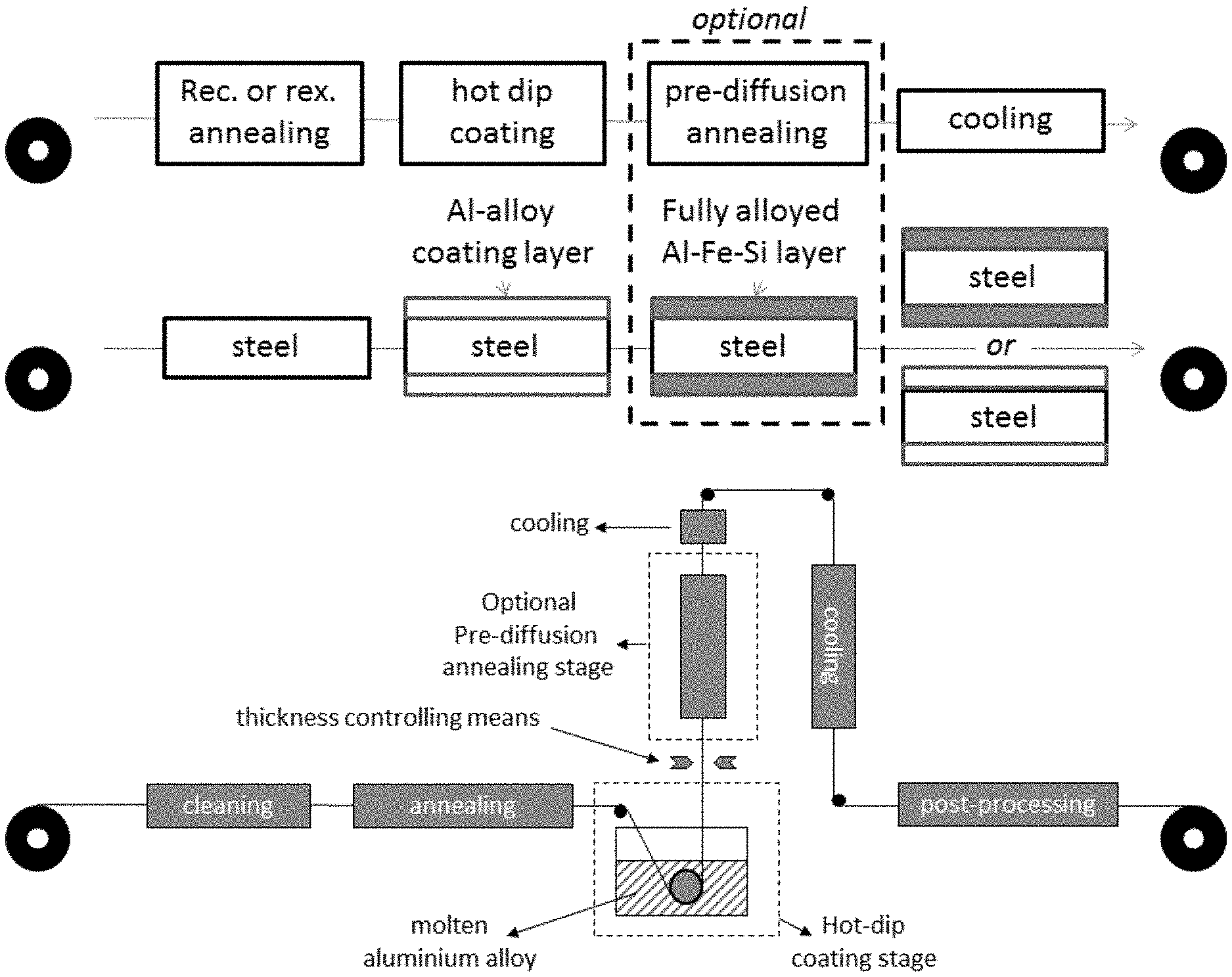
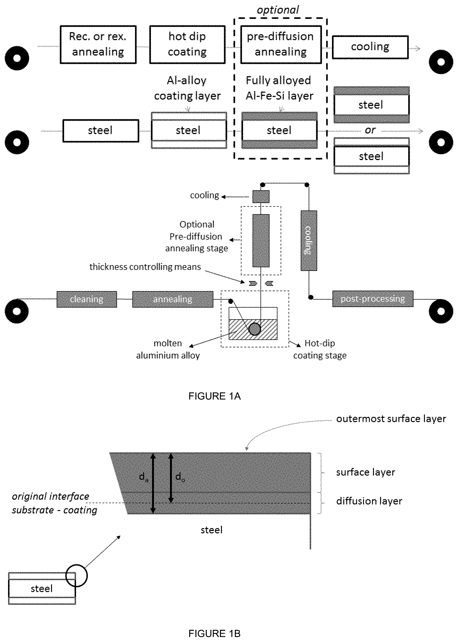
[0059] In FIG. 1A the process according to the invention is summarised. The steel strip is passed through an optional cleaning section to remove the undesired remnants of previous processes such as scale, oil residue etc. The clean strip is then led though the optional annealing section, which in case of a hot rolled strip may only be used for heating the strip to allow hot-dip coating (so-called heat-to-coat cycle) or in case of a cold-rolled strip may be used for a recovery or recrystallisation annealing. After the annealing the strip is led to the hot-dip coating stage where the strip is provided with the aluminium alloy coating layer according to the invention. Thickness control means for controlling the thickness of the aluminium alloy coating layer are shown disposed between the hot-dip coating stage and the subsequent optional pre-diffusion annealing stage. In the optional pre-diffusion annealing stage the aluminium alloy coating layer is transformed into a fully-alloyed aluminium-iron-silicon layer. If no pre-diffusion annealing treatment is executed, then the alloying condition of the aluminium alloy coating layer upon coiling will be pretty much the same as the aluminium alloy coating layer immediately after having passed the thickness controlling means. The coated strip (whether optionally pre-diffused or not) is post-processed (such as optional temper rolling or tension levelling) before being coiled. The cooling of the coated strip after the thickness controlling means usually takes place in two steps, wherein the cooling immediately after the thickness controlling means is intended to prevent any sticking or damage of the aluminium alloy coating layer to turning rolls, and is usually executed with an air or mist cooling at a cooling rate of about between 10 and 30.degree. C./s and further on in the line the strip with the aluminium alloy coating layer is cooled quickly, usually by quenching in water. It is noted that the effect of the cooling is largely thermal to prevent damage to the line and the aluminium alloy coating layer, and that the effect of the cooling on the properties of the steel substrate are negligible. The strip or sheet produced in accordance with FIG. 1A (i.e. as-coated or pre-diffused) can then be used in a hot-forming process according to the invention.
[0060] In FIG. 1B a close-up of the layer structure after the hot-forming process is shown with the surface layer and the diffusion layer clearly identified. Also clearly visible is the original interface between the steel substrate and the aluminium alloy coating layer "as coated" (d.sub.0) and the increase of the thickness after the annealing in the hot forming process (d.sub.a). The diffusion layer has grown into the steel substrate and therefore d.sub.0<d.sub.a. The layer structure of the surface layer is not shown, because this is dependent on the annealing temperature, annealing time and composition of the aluminium alloy coating layer. The definition of outermost surface layer is schematically indicated.
EXAMPLES
[0061] Hot-formed coated steel products were produced from a steel substrate having the composition as given in Table 1.
TABLE-US-00004 TABLE 1 Composition of steel substrate, balance Fe and inevitable impurities. 1.5 mm, cold-rolled, full-hard condition. C Mn Cr Si P S Al B Ca wt. % wt. % wt. % wt. % wt. % wt. % wt. % ppm ppm 0.20 2.18 0.64 0.055 0.010 0.001 0.036 0 17
[0062] Aluminium alloy coating layers were provided onto the steel substrate by immersing the substrate in a molten aluminium alloy bath (a.k.a. hot-dipping or hot-dip coating), and the silicon content of the bath, and thus the aluminium alloy coating layers was 1.1 and 9.6 wt. % respectively. The bath temperature was 700.degree. C., the immersion time was 3 seconds, and the thickness of the aluminium alloy coating layers was 30 .mu.m.
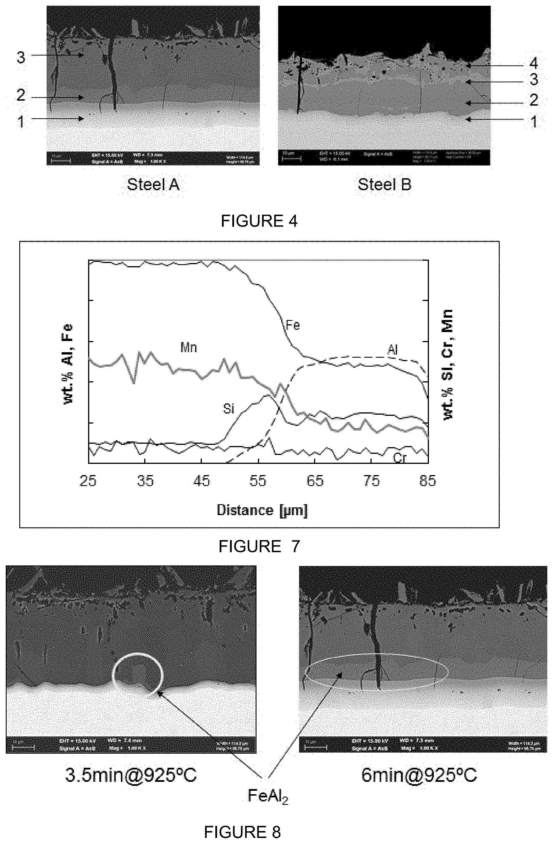
[0063] After applying the coating, sheets of steel were heated for 6 minutes in a radiation furnace at a temperature of 925.degree. C. At the end of heating the blanks were transferred in less than 10 seconds to a press and subsequently stamped and quenched. After hot stamping the steels were covered with an aluminium alloy coating layer of 40-50 .mu.m thickness. The increase of the thickness of the aluminium alloy coating layer is caused by the diffusion and alloying processes taking place in the surface layer and by the formation of the diffusion layer between the surface layer and the steel substrate. This diffusion layer is formed by diffusion of aluminium into the steel substrate, thereby enriching the steel substrate with aluminium to a level that the steel substrate locally does not transform to austenite any longer, and stays ferritic during the hot stamping and this ductile layer stops any surface cracks from reaching the steel substrate. The coating of the steel coated with a 1.1% Si layer (Sample A) consists of three layers while in the coating of the steel coated with the 9.6% Si (Sample B) four layers can be distinguished, as illustrated in FIG. 4. In sample B the presence of a continuous layer of .tau.-phase in the aluminium alloy coating layer (indicated with 3 in FIG. 4) as well as significant amounts of the same phase on the surface can be identified.
[0064] Energy-dispersive X-ray spectroscopy (EDX or EDS), is an analytical technique used for the elemental analysis or chemical characterization of a sample. It relies on an interaction of some source of X-ray excitation and a sample. Its characterization capabilities are due in large part to the fundamental principle that each element has a unique atomic structure allowing a unique set of peaks on its electromagnetic emission spectrum[2] (which is the main principle of spectroscopy). To stimulate the emission of characteristic X-rays from a specimen or a beam of X-rays, is focused into the sample being studied. At rest, an atom within the sample contains ground state (or unexcited) electrons in discrete energy levels or electron shells bound to the nucleus. The incident beam may excite an electron in an inner shell, ejecting it from the shell while creating an electron hole where the electron was. An electron from an outer, higher-energy shell then fills the hole, and the difference in energy between the higher-energy shell and the lower energy shell may be released in the form of an X-ray. The number and energy of the X-rays emitted from a specimen can be measured by an energy-dispersive spectrometer. As the energies of the X-rays are characteristic of the difference in energy between the two shells and of the atomic structure of the emitting element, EDS allows the elemental composition of the specimen to be measured (https://en.wikipedia.org/wiki/Energy-dispersive_X-ray_spectroscopy).
[0065] Energy Dispersive X-ray analysis (EDX or EDS) of the sub layers revealed the following structure for sample A: [0066] layer 1: Diffusion layer [0067] layer 2: FeAl.sub.2 (46-52 wt. % Fe, 44-50 wt. % Al and <3 wt. % Si) [0068] layer 3: Fe.sub.2Al.sub.5 (40-47 wt. % Fe, 51-58 wt. % Al and <3 wt. % Si) In the four layered structure of sample B the identified phases were: [0069] layer 1: Diffusion layer [0070] layer 2: Fe.sub.2Al.sub.5 [0071] layer 3: .tau.-phase (Fe.sub.2SiAl.sub.2) [0072] layer 4: Fe.sub.2Al.sub.5 Note that these layer structures are dependent on the annealing time. After prolonged annealing the composition of layer 2 of sample B will likely become FeAl.
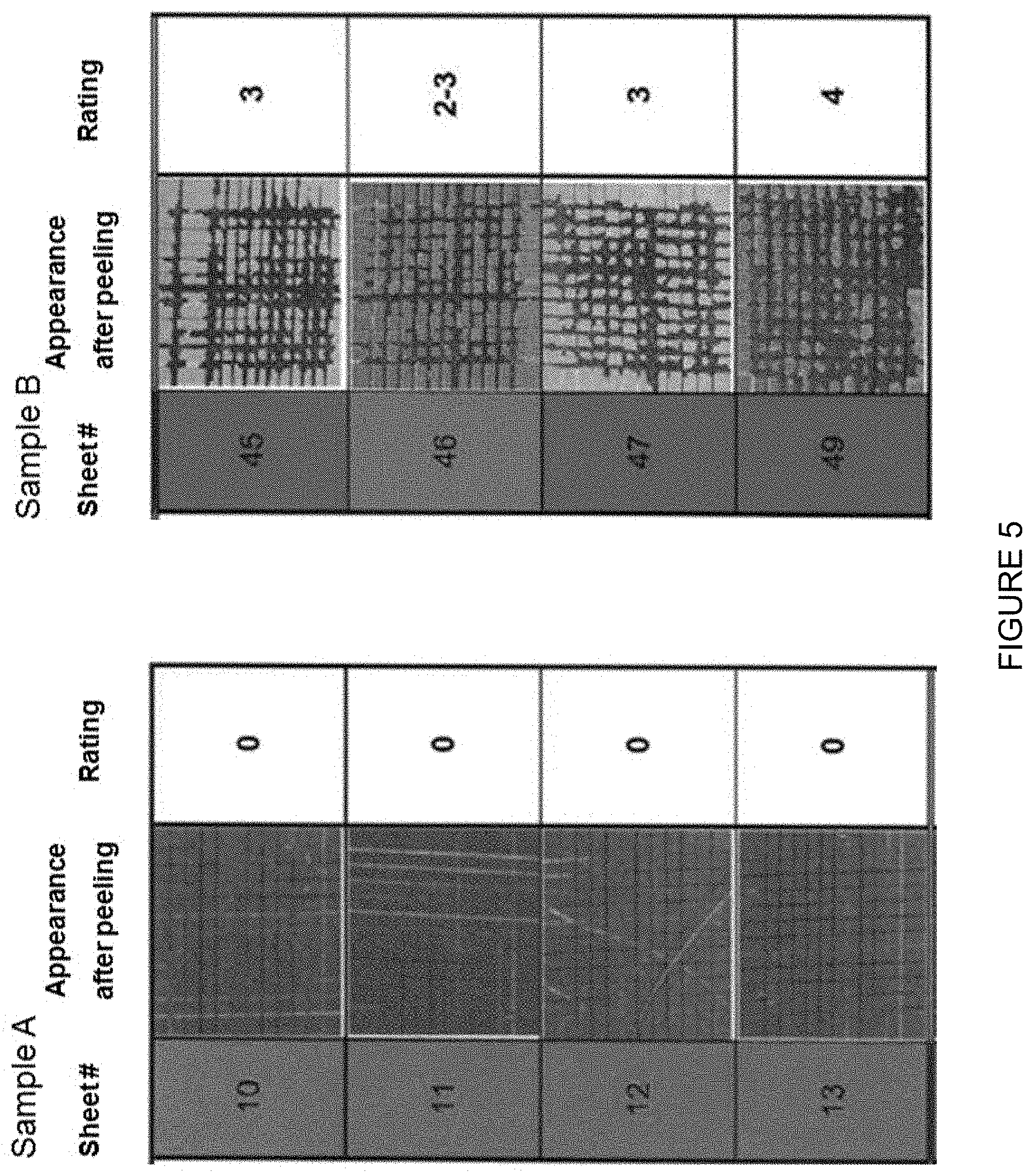
[0073] In addition both layers contain low concentrations Cr and Mn. EPMA line scans on cross sections of the steel coated with Al-1.1 wt. % Si revealed Cr and Mn diffused from the substrate into the layers. Concentrations found in the coating are about 50% of the concentration in the substrate. An example is given in FIG. 7 for heat treatment of 6 minutes at 900.degree. C. It is noted that intermetallic layer 1 can be very thin, even almost absent for short and/or low annealing temperatures (see FIG. 8).
[0074] On the hot formed panels an E-coat was applied by the following process steps:
TABLE-US-00005 Time Temperature Process step Agent [s] [.degree. C.] Alkaline degreasing Gardoclean S5176 90 55 Spray rinsing Tap water 60 room Activating Gardolene V6513 60 24 Phosphating Gardobond 24 TA 180 51 Dip rinsing Deionised water 60 room E-coating Guard 900 BASF 300 32 Dip rinsing Deionised water 60 room Drying n.a. 30 room Curing n.a. 1380 160
[0075] E-coat adhesion of four sheets of sample A and B was tested by immersion of the panels in deionised water of 50.degree. C. during 10 days. After removing the panels from the warm water bath a cross hatch pattern per sheet was made according NEN-EN-ISO 2409 (June 2007). Paint adhesion was tested on the cross-cut area by a tape peel off test as described in aforementioned standard. Test results were ranked according table 1 of this standard.
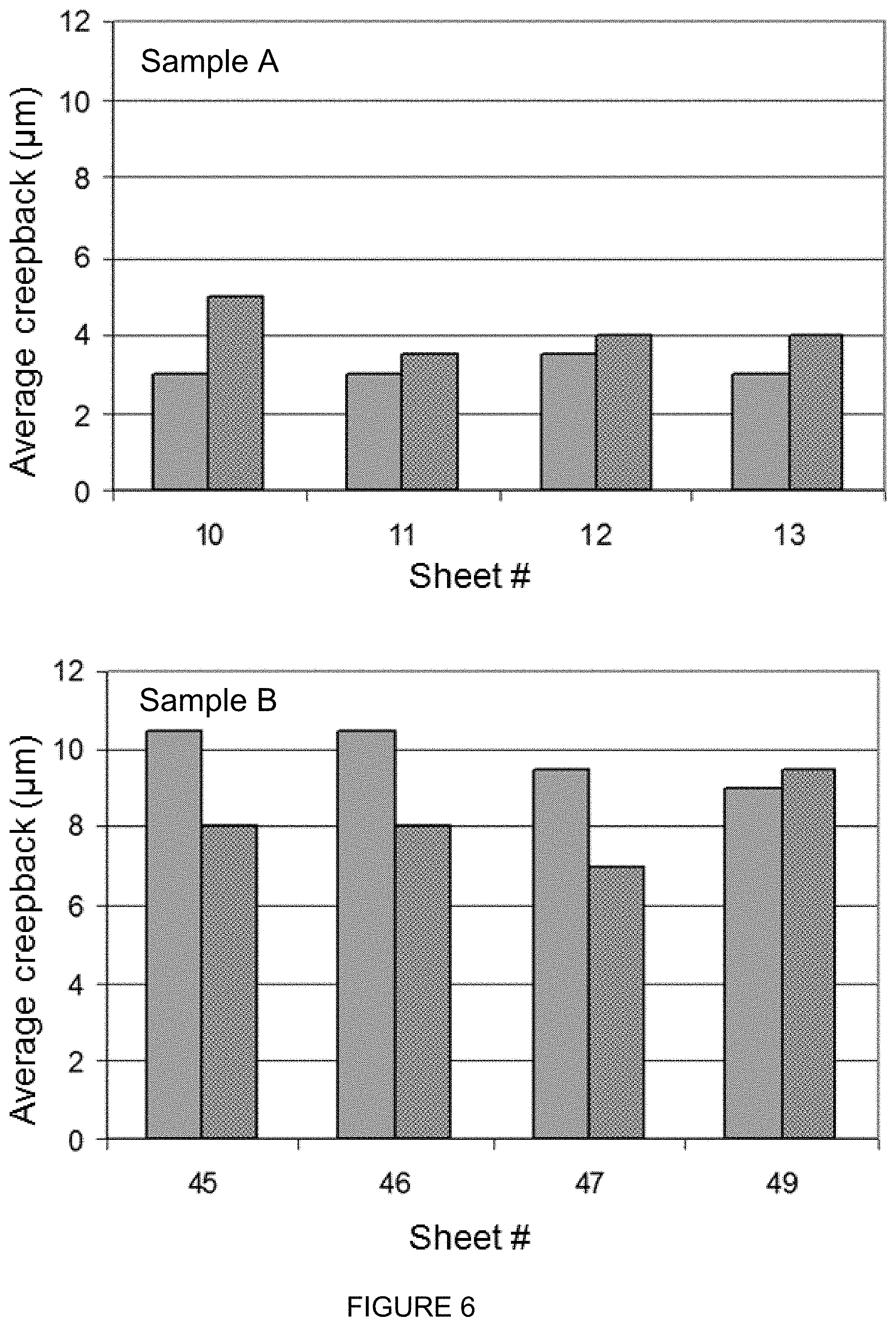
[0076] The four sheets of sample A exhibit excellent paint adhesion. The edges of the cuts are completely intact and none of the squares of the lattice is detached (FIG. 5). Therefore the adhesion performance is rated as 0. The four sheets of sample B show a poor paint adhesion. The rating varies between 2 and 4, meaning cross-cut areas of 15 to 65% have flaked off.
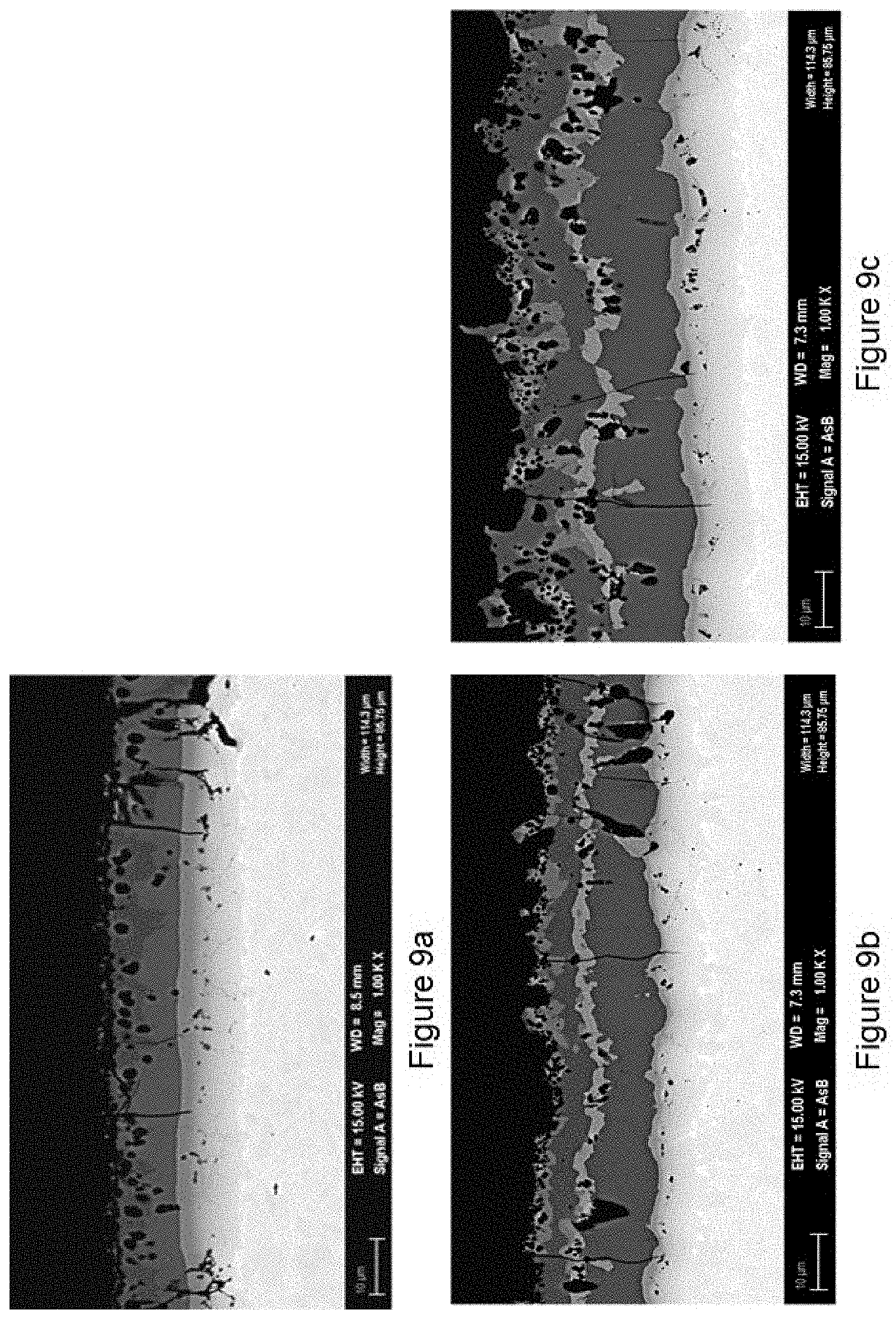
[0077] A typical test to determine whether a coated product meets the automotive manufacturer's requirements is the scribe undercreep test. In this test loss of E-coat adhesion due to corrosive creepback at a deliberately made scribe is determined. These test results are considered to be an indicator for cosmetic corrosion in service. E-coated sheets used for this test were produced according the route described above. Scribes were made on the sheets through the E-coat and metallic coating just into the substrate. Two types of scribes per panel were made, one with a Sikkens tool and one with a van Laar knife. Sheets were tested in a corrosion cabinet using the VDA233-102 accelerated corrosion test. Corrosive creepback from the scribe lines was evaluated after 10 weeks of testing. Average creepback width was determined over a scribe length of 70 mm. As a measurement tool rectangular transparent templates with a length of 70 mm and a varying width in steps of 0.5 mm from 1 to 15 mm were used. The width of the template with an area matching best with the delaminated area was taken as average creepback width. Four sheets of sample A and of B were scribed and tested. The results showed a significant improvement of undercreep resistance of A compared to B. Measured undercreep on A range from 3 to 4 mm while on B values between 7 and 10.5 mm were found.
[0078] In another example aluminium coating layers were provided onto the 1.5 mm cold-rolled full hard steel substrate by hot dipping, and the silicon content of the coating bath was 1.9 wt. % and 9.8 wt % respectively. The coating bath temperature was 690.degree. C., the immersion time was 5 seconds, and the resulting layer thickness was adjusted from 15 to 25 .mu.m, as indicated in the following table.
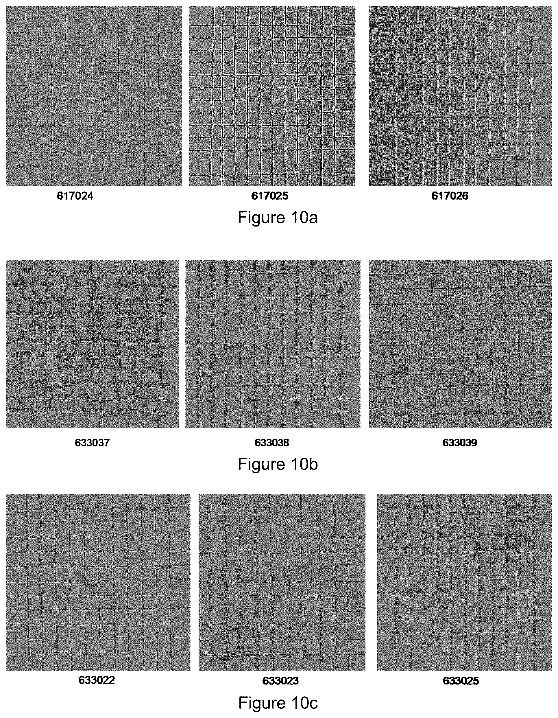
TABLE-US-00006 TABLE 2 Si bath concentration, layer thickness and furnace conditions. Bath Si Layer thickness Furnace T Furnace t Series Sheet id [wt %] [.mu.m] [.degree. C.] [minutes] 1 617024 1.9 15 925 3.5 617025 1.9 15 925 3.5 617026 1.9 15 925 3.5 2 633037 9.8 15 925 4.5 633038 9.8 15 925 4.5 633039 9.8 15 925 4.5 3 633022 9.8 25 925 6.0 633023 9.8 25 925 6.0 633025 9.8 25 925 6.0
TABLE-US-00007 TABLE 3 Paint adhesion rating Paint Bath Si Area .tau. adhesion Series Sheet id [wt %] [%] C.tau. rating 1 617024 1.9 0 0 1 617025 1.9 0 0 1 617026 1.9 0 0 1 2 633037 9.8 >10 1 3 633038 9.8 >10 1 2-3 633039 9.8 >10 1 2 3 633022 9.8 >10 1 2 633023 9.8 >10 1 3 633025 9.8 >10 1 3
[0079] After coating application the sheets of steel were heated for 3.5 to 6 minutes, depending on coating thickness and Si level, in a radiation furnace at a temperature of 925.degree. C. At the end of heating the blanks were transferred in less than 10 seconds to a press and subsequently stamped and quenched. After hot stamping the metallic coating layer was measured and was between 20-50 .mu.m.
[0080] After stamping the coating of the steel coated with a 1.9% Si layer is completely free of Fe.sub.2SiAl.sub.2 (.tau.-phase) while the area fraction of Fe.sub.2SiAl.sub.2 (.tau.-phase) in the surface layer of the steels coated with 9.8% Si is >10%. Furthermore the contiguity of .tau.-phase (CT) in the 1.9% Si coating is 0 and CT of the 9.8% Si coatings is 1 which is far above the preferred value of at most 0.4. Cross section images illustrating the microstructural differences of the coatings are shown in FIG. 9a to c.
[0081] On the hot formed panels an E-coat was applied by going through the same process steps and tested in the same way as explained above. The three sheets of series 1 exhibit very good paint adhesion. The edges of the cuts are to a large extent intact and only very minor flaking off is observed (FIG. 10a). Therefore the adhesion performance is rated as 1. The sheets of series 2 show a poor paint adhesion. The rating varies between 2 and 3, meaning cross-cut areas of 15 to 35% have flaked off (FIG. 10b). The sheets of series 3 show similar performance and are also rated between 2 and 3 (FIG. 10c).
[0082] The invention is further explained by means of the following, non-limiting figures.
[0083] In FIG. 1A the process according to the invention is summarised and has been described in detail above as well as FIG. 1B in which the build-up and development of the coating layer is described.
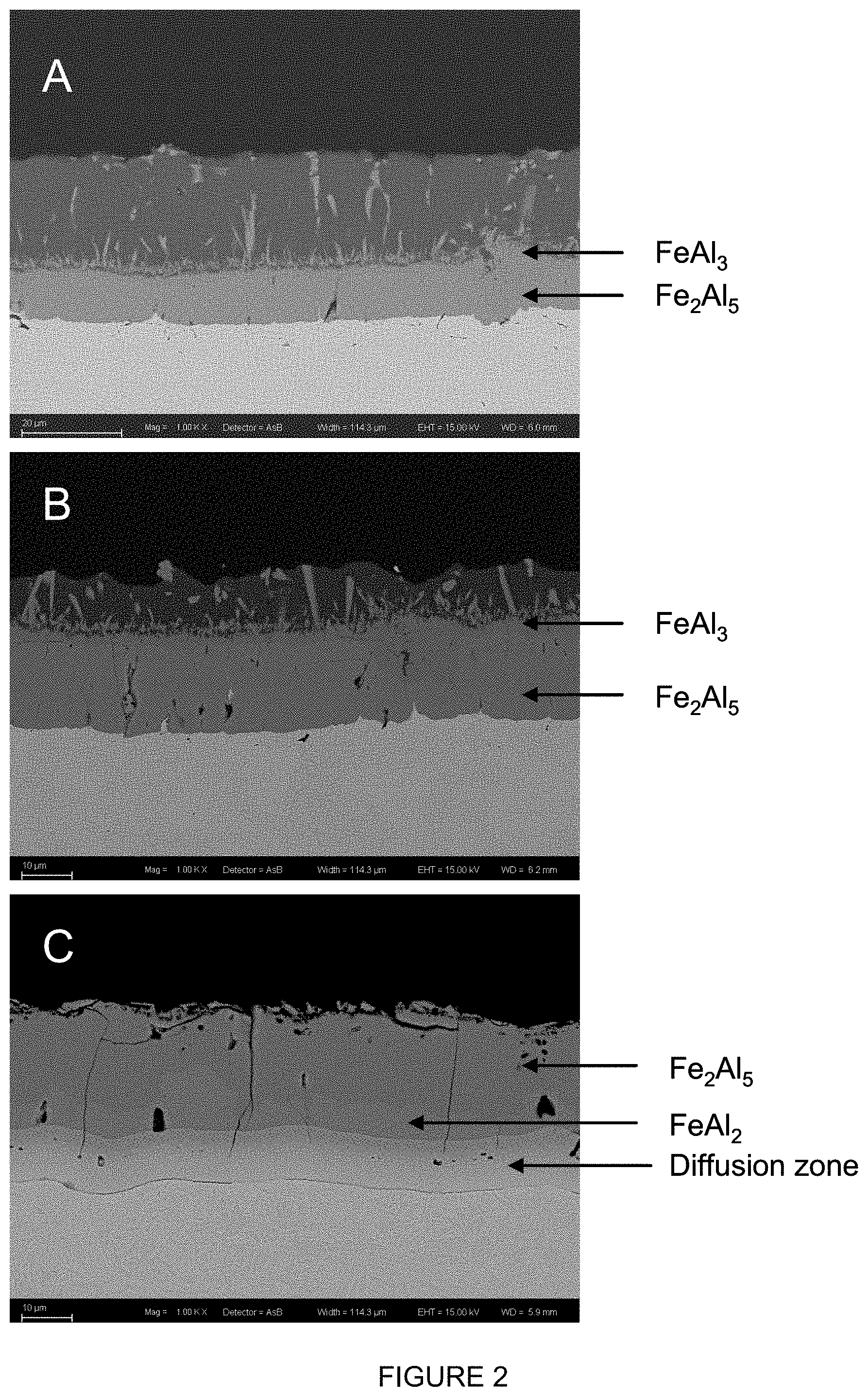
[0084] FIG. 2 shows the development of the different layers of intermetallic compounds during heat treatment of an steel substrate provided with an aluminium alloy coating comprising 1.6 wt. % Si. Figure A shows the as-coated layer, with the layers that are formed immediately after the immersion, and the top layer having the composition of the bath, B shows the development during reheating once the sample has reached 700.degree. C. and C is the situation after annealing at 900.degree. C. for 5 minutes. In sample C the diffusion zone is now clearly visible, and the top layer having the composition of the bath has completely vanished (EDS: acceleration voltage (EHT) 15 keV, working distance (wd) 6.0, 6.2 and 5.9 mm)
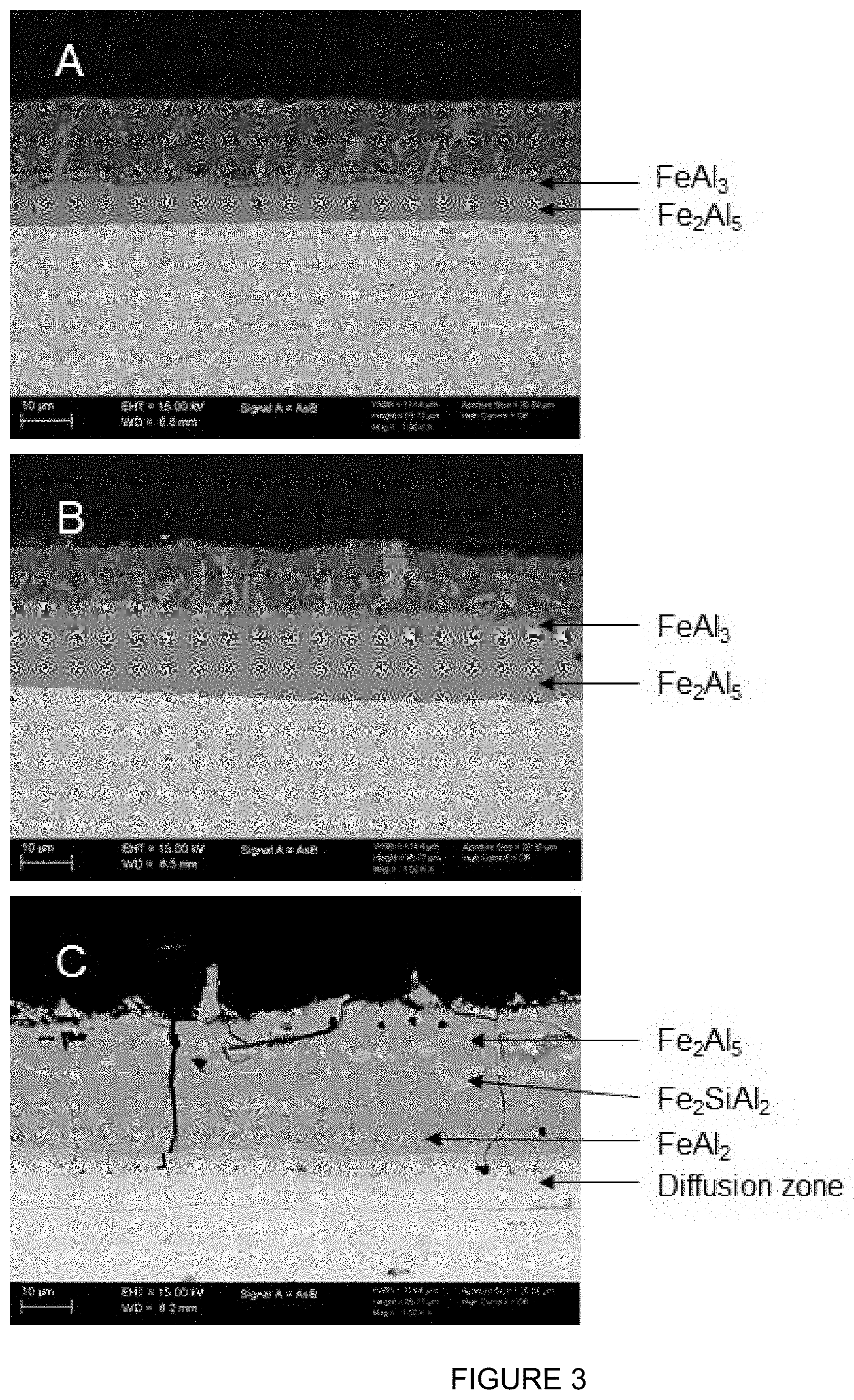
[0085] FIG. 3 shows the development of the different layers of intermetallic compounds during heat treatment of an steel substrate provided with an aluminium alloy coating comprising 3.0 wt. % Si (EHT 15 keV, wd 6.6, 6.5, 6.2 mm respectively). Figure A shows the as-coated layer, with the layers that are formed immediately after the immersion, and the top layer having the composition of the bath, B shows the development during reheating once the sample has reached 850.degree. C. and C is the situation after annealing at 900.degree. C. for 7 minutes. In sample C the diffusion zone is now clearly visible, and the top layer having the composition of the bath has completely vanished. Also visible is a degree of .tau.-phase (Fe.sub.2SiAl.sub.2) which is dispersed in the Fe.sub.2Al.sub.5 layer, and does not form a continuous layer. C.sub..tau..ltoreq.0.4.
[0086] FIG. 4 shows the development of the different layers of intermetallic compounds during heat treatment of an steel substrate provided with an aluminium alloy coating comprising 1.1 wt. % Si (Sample A) and 9.6 wt. % (Sample B) on a hot-formed product which was heated for 6 minutes at 925.degree. C. (EHT 15 keV, wd 7.3 and 6.1 mm). The continuous .tau.-phase (Fe.sub.2SiAl.sub.2) layer in sample B is clearly visible, as well as the notable absence thereof in sample A.
[0087] FIG. 5 shows the results of the paint adhesion tests of samples A and B which have been discussed herein above. FIG. 6 shows the average undercreep values of samples A and B.
[0088] FIG. 7 shows the diffusion profile of sample A after annealing for 6 minutes at 900.degree. C.
[0089] FIG. 8 (EHT 15 keV, wd 7.4 and 7.3 mm). shows the emergence of the FeAl.sub.2 layer for different heat treatment times of sample A. After 3.5 minutes at 925.degree. C. the FeAl.sub.2-layer starts to appear, whereas after 6 minutes there is a layer of this compound present. Also notable is the crack-stopping ability of the diffusion layer in the 6 minute sample.
[0090] FIG. 9 shows the cross sections of an hot-formed specimen having 1.9 wt. % Si (FIG. 9a) in the aluminium coating layer or 9.8 wt. % Si (FIGS. 9b and 9c). FIGS. 10a to 10 c show the paint adhesion performance of these samples.
* * * * *
References
D00000
D00001
D00002
D00003
D00004
D00005
D00006
D00007
D00008
XML
uspto.report is an independent third-party trademark research tool that is not affiliated, endorsed, or sponsored by the United States Patent and Trademark Office (USPTO) or any other governmental organization. The information provided by uspto.report is based on publicly available data at the time of writing and is intended for informational purposes only.
While we strive to provide accurate and up-to-date information, we do not guarantee the accuracy, completeness, reliability, or suitability of the information displayed on this site. The use of this site is at your own risk. Any reliance you place on such information is therefore strictly at your own risk.
All official trademark data, including owner information, should be verified by visiting the official USPTO website at www.uspto.gov. This site is not intended to replace professional legal advice and should not be used as a substitute for consulting with a legal professional who is knowledgeable about trademark law.