Conveyance Apparatus And Image Forming System Including Conveyance Apparatus
Kawasaki; Yasuhiro ; et al.
U.S. patent application number 16/688883 was filed with the patent office on 2020-05-28 for conveyance apparatus and image forming system including conveyance apparatus. The applicant listed for this patent is CANON KABUSHIKI KAISHA. Invention is credited to Kazushi Ino, Koji Kawamura, Yasuhiro Kawasaki, Kazuhide Okuno.
| Application Number | 20200165090 16/688883 |
| Document ID | / |
| Family ID | 70770275 |
| Filed Date | 2020-05-28 |


View All Diagrams
| United States Patent Application | 20200165090 |
| Kind Code | A1 |
| Kawasaki; Yasuhiro ; et al. | May 28, 2020 |
CONVEYANCE APPARATUS AND IMAGE FORMING SYSTEM INCLUDING CONVEYANCE APPARATUS
Abstract
A conveyance apparatus includes a change conveyance unit. In a case where a first sheet in a sheet storage unit included in the feeding apparatus is fed in a landscape orientation to the conveyance apparatus, the change conveyance unit changes a conveyance orientation of the first sheet to a portrait orientation. The landscape orientation is an orientation in which a short side of the first sheet is parallel to a sheet conveyance direction of the first sheet. The portrait orientation is an orientation in which a long side of the first sheet is parallel to the sheet conveyance direction. The change conveyance unit changes the conveyance orientation of the first sheet from the landscape orientation to the portrait orientation on a substantially horizontal region between the image forming apparatus and the feeding apparatus.
| Inventors: | Kawasaki; Yasuhiro; (Yokohama-shi, JP) ; Ino; Kazushi; (Suntou-gun, JP) ; Kawamura; Koji; (Yokohama-shi, JP) ; Okuno; Kazuhide; (Mishima-shi, JP) | ||||||||||
| Applicant: |
|
||||||||||
|---|---|---|---|---|---|---|---|---|---|---|---|
| Family ID: | 70770275 | ||||||||||
| Appl. No.: | 16/688883 | ||||||||||
| Filed: | November 19, 2019 |
| Current U.S. Class: | 1/1 |
| Current CPC Class: | B65H 2404/74 20130101; B65H 9/106 20130101; B65H 2301/33216 20130101; B65H 2801/06 20130101; B65H 5/062 20130101; B65H 5/38 20130101; B65H 2402/10 20130101; B65H 29/20 20130101; B65H 2404/72 20130101; B65H 2301/33312 20130101; B65H 2301/33222 20130101 |
| International Class: | B65H 9/10 20060101 B65H009/10; B65H 29/20 20060101 B65H029/20; B65H 5/06 20060101 B65H005/06 |
Foreign Application Data
| Date | Code | Application Number |
|---|---|---|
| Nov 27, 2018 | JP | 2018-221731 |
| Nov 27, 2018 | JP | 2018-221732 |
| Dec 5, 2018 | JP | 2018-228337 |
| Sep 19, 2019 | JP | 2019-170515 |
Claims
1. A conveyance apparatus that is connected to both an image forming apparatus and a feeding apparatus and conveys sheets, the image forming apparatus being configured to convey a sheet in an orientation in which a long side of the sheet is parallel to a sheet conveyance direction and form an image on the conveyed sheet, the feeding apparatus being configured to feed a sheet toward the image forming apparatus, the conveyance apparatus comprising: a change conveyance unit configured to change a conveyance orientation of a first sheet to a portrait orientation in a case where the first sheet in a sheet storage unit included in the feeding apparatus is fed in a landscape orientation to the conveyance apparatus, the portrait orientation being an orientation in which a long side of the first sheet is parallel to a sheet conveyance direction of the first sheet, the landscape orientation being an orientation in which a short side of the first sheet is parallel to the sheet conveyance direction, wherein the conveyance apparatus is disposed on a lower side of the image forming apparatus and on an upper side of the feeding apparatus, and wherein the change conveyance unit changes the conveyance orientation of the first sheet from the landscape orientation to the portrait orientation on a substantially horizontal region between the image forming apparatus and the feeding apparatus.
2. The conveyance apparatus according to claim 1, wherein the conveyance apparatus conveys the first sheet in the portrait orientation to the image forming apparatus.
3. The conveyance apparatus according to claim 2, wherein the change conveyance unit includes a first conveyance unit configured to convey the first sheet conveyed from the feeding apparatus in the landscape orientation, and a reference member configured to be in contact with the first sheet conveyed by the first conveyance unit.
4. The conveyance apparatus according to claim 3, wherein the change conveyance unit includes a second conveyance unit configured to convey the first sheet while keeping the first sheet in contact with a guide surface included in the reference member and pivoting the first sheet.
5. The conveyance apparatus according to claim 4, wherein the change conveyance unit includes a third conveyance unit configured to convey the first sheet in the portrait orientation along the reference member in a manner moving the first sheet away from the reference member.
6. The conveyance apparatus according to claim 2, wherein the change conveyance unit includes a first conveyance unit configured to convey the first sheet conveyed from the feeding apparatus in the landscape orientation, and a second conveyance unit configured to convey the first sheet while changing the conveyance orientation of the first sheet from the landscape orientation to the portrait orientation, the second conveyance unit being disposed downstream of the first conveyance unit with respect to the sheet conveyance direction.
7. The conveyance apparatus according to claim 6, wherein the second conveyance unit includes a first conveyance roller pair and a second conveyance roller pair that are disposed in a direction intersecting the sheet conveyance direction, and wherein a speed at which the first conveyance roller pair conveys the first sheet is different from a speed at which the second conveyance roller pair conveys the first sheet.
8. The conveyance apparatus according to claim 1, further comprising an adjustment unit configured to adjust, in accordance with a status of the image forming apparatus, a conveyance speed of the first sheet in the portrait orientation to which a conveyance orientation of the first sheet has been changed by the change conveyance unit.
9. The conveyance apparatus according to claim 8, wherein the adjustment unit is disposed in an upper side of the change conveyance unit, and wherein a sheet conveyance direction of the first sheet by the change conveyance unit is opposite to a sheet conveyance direction of the first sheet by the adjustment unit.
10. An image forming system comprising: an image forming apparatus configured to convey a sheet in an orientation in which a long side of the sheet is parallel to a sheet conveyance direction and form an image on the conveyed sheet; a feeding apparatus configured to feed a sheet toward the image forming apparatus; and a conveyance apparatus configured to be connected to both the image forming apparatus and the feeding apparatus and convey a sheet; wherein the conveyance apparatus is arranged on a lower side of the image forming apparatus and on an upper side of the feeding apparatus, wherein the conveyance apparatus includes a change conveyance unit configured to change a conveyance orientation of a first sheet to a portrait orientation in a case where the first sheet in a sheet storage unit included in the feeding apparatus is fed in a landscape orientation to the conveyance apparatus, the portrait orientation being an orientation in which a long side of the first sheet is parallel to a sheet conveyance direction of the first sheet, the landscape orientation being an orientation in which a short side of the first sheet is parallel to the sheet conveyance direction, and wherein the change conveyance unit changes the conveyance orientation of the first sheet from the landscape orientation to the portrait orientation on a substantially horizontal region between the image forming apparatus and the feeding apparatus.
11. The image forming system according to claim 10, wherein the conveyance apparatus conveys the first sheet in the portrait orientation to the image forming apparatus.
12. An image forming system according to claim 11, wherein the change conveyance unit includes a first conveyance unit configured to convey the first sheet conveyed from the feeding apparatus in the landscape orientation, and a reference member configured to be in contact with the first sheet conveyed by the first conveyance unit.
13. An image forming system according to claim 12, wherein the change conveyance unit includes a second conveyance unit configured to convey the first sheet while keeping the first sheet in contact with a guide surface included in the reference member and pivoting the first sheet.
14. The image forming system according to claim 13, wherein the change conveyance unit includes a third conveyance unit configured to convey the first sheet in the portrait orientation along the reference member in a manner moving the first sheet away from the reference member.
15. The image forming system according to claim 11, wherein the change conveyance unit includes a first conveyance unit configured to convey the first sheet conveyed from the feeding apparatus in the landscape orientation, and a second conveyance unit configured to convey the first sheet while changing the conveyance orientation of the first sheet from the landscape orientation to the portrait orientation, the second conveyance unit being disposed downstream of the first conveyance unit with respect to the sheet conveyance direction.
16. The image forming system according to claim 15, wherein the second conveyance unit includes a first conveyance roller pair and a second conveyance roller pair that are disposed in a direction intersecting the sheet conveyance direction, and wherein a speed at which the first conveyance roller pair conveys the first sheet is different from a speed at which the second conveyance roller pair conveys the first sheet.
17. The image forming system according to claim 10, wherein the conveyance apparatus includes an adjustment unit configured to adjust, in accordance with a status of the image forming apparatus, a conveyance speed of the first sheet in the portrait orientation to which a conveyance orientation of the first sheet has been changed by the change conveyance unit.
18. An image forming system according to claim 17, wherein the adjustment unit is disposed in an upper side of the change conveyance unit, and wherein a sheet conveyance direction of the first sheet by the change conveyance unit is opposite to a sheet conveyance direction of the first sheet by the adjustment unit.
Description
BACKGROUND OF THE DISCLOSURE
Field of the Disclosure
[0001] The present disclosure relates to a conveyance apparatus for conveying sheets and an image forming system.
Description of the Related Art
[0002] In recent years, images can be formed on a large number of sheets in a short time period with increase in image forming speed of image forming apparatuses. To eliminate inconvenience of loading sheets of paper on image forming apparatuses having a high image forming speed, a sheet feeding apparatus (hereinafter referred to as a feeding unit) on which a large volume of paper can be stacked is connected to the image forming apparatuses.
[0003] In general, image forming apparatuses capable of forming images on up to A4 size sheets convey sheets set in an orientation in which the long side of sheets is parallel to a sheet conveyance direction (hereinafter referred to as a portrait orientation). Feeding units that can be connected to an image forming apparatus capable of printing up to A4 size sheets store therein sheets in a single stack in the portrait orientation to conform to an image forming apparatus that supports A4 size sheet printing.
[0004] Meanwhile, image forming apparatuses capable of forming images on up to A3 size sheets convey A3 size sheets in the portrait orientation and convey A4 size sheets in an orientation in which the short side of A4 size sheets is parallel to the sheet conveyance direction (hereinafter referred to as a landscape orientation). Some feeding units that can be connected to an image forming apparatus supporting printing on up to A3 size sheets store therein A4 size sheets in two stacks side by side in the landscape orientation which is the orientation same as an A4 size sheets conveyance orientation in the image forming apparatus.
[0005] Japanese Patent Application Laid-Open No. H05-213487 discusses an image forming apparatus capable of forming images on up to A3 size sheets. Japanese Patent Application Laid-Open No. H05-213487 also discusses that A4 size sheets are stored in two stacks side by side in the landscape orientation and further discusses a change unit configured to convey the A4 size sheets after changing the orientation of each A4 size sheet stored in the landscape orientation to the portrait orientation.
[0006] The configuration of the image forming apparatus discussed in Japanese Patent Application Laid-Open No. H5-213487, however, may lead increase in height of the image forming apparatus as a whole since a change conveyance unit configured to change the orientation of sheets while sheets are conveyed in a vertical direction.
SUMMARY OF THE DISCLOSURE
[0007] According to an aspect of the present disclosure, a conveyance apparatus is connected to both an image forming apparatus and a feeding apparatus and conveys sheets. The image forming apparatus is configured to convey a sheet in an orientation in which a long side of the sheet is parallel to a sheet conveyance direction and form an image on the conveyed sheet. The feeding apparatus is configured to feed a sheet toward the image forming apparatus. The conveyance apparatus includes a change conveyance unit configured to change a conveyance orientation of a first sheet to a portrait orientation in a case where the first sheet in a sheet storage unit included in the feeding apparatus is fed in a landscape orientation to the conveyance apparatus. The portrait orientation is an orientation in which a long side of the first sheet is parallel to a sheet conveyance direction of the first sheet, the landscape orientation being an orientation in which a short side of the first sheet is parallel to the sheet conveyance direction. The conveyance apparatus is disposed on a lower side of the image forming apparatus and on an upper side of the feeding apparatus, and wherein the change conveyance unit changes the conveyance orientation of the first sheet from the landscape orientation to the portrait orientation on a substantially horizontal region between the image forming apparatus and the feeding apparatus.
[0008] Further features and aspects of the present disclosure will become apparent from the following description of example embodiments with reference to the attached drawings.
BRIEF DESCRIPTION OF THE DRAWINGS
[0009] FIG. 1 is a diagram illustrating a perspective view of an entire image forming system according to a first example embodiment in which the left side of an image forming apparatus is aligned along the left side of a feeding apparatus.
[0010] FIG. 2 is a diagram illustrating a perspective view of an entire image forming system according to the first example embodiment in which the right side of the image forming apparatus is aligned along the right side of the feeding apparatus.
[0011] FIG. 3 is a diagram illustrating an exploded perspective view of the image forming system according to the first example embodiment.
[0012] FIG. 4 is a diagram illustrating a side view of the image forming system according to the first example embodiment.
[0013] FIG. 5 is a diagram illustrating a cross-sectional view of the entire image forming system according to the first example embodiment.
[0014] FIG. 6 is a diagram illustrating a cross-sectional view of a change conveyance apparatus according to the first example embodiment.
[0015] FIG. 7 is a diagram illustrating a perspective view of a change conveyance unit according to the first example embodiment.
[0016] FIG. 8 is a diagram illustrating a top view of the change conveyance unit according to the first example embodiment.
[0017] FIG. 9 is a comparison diagram illustrating the image forming system according to the first example embodiment and an image forming system according to an comparative example.
[0018] FIG. 10 is a diagram illustrating a cross-sectional view of an entire image forming system according to a modification example of the first example embodiment.
[0019] FIG. 11 is a diagram illustrating a cross-sectional view of a change conveyance apparatus according to the modification example of the first example embodiment.
[0020] FIG. 12 is a diagram illustrating a cross-sectional view of the change conveyance apparatus according to the modification example of the first example embodiment.
[0021] FIG. 13 is a diagram illustrating a top view of the change conveyance apparatus according to the modification example of the first example embodiment.
[0022] FIG. 14 is a diagram illustrating a cross-sectional view of a change conveyance apparatus according to the second example embodiment.
[0023] FIG. 15 is a diagram illustrating a cross-sectional view of a change conveyance apparatus according to the second example embodiment.
[0024] FIG. 16 is a diagram illustrating a perspective view of an image forming system according to a third example embodiment.
[0025] FIG. 17 is a diagram illustrating a cross-sectional view of the image forming system according to the third example embodiment.
[0026] FIG. 18 is a diagram illustrating a cross-sectional view of an image forming system according to a comparative example of the third example embodiment.
[0027] FIG. 19 is a diagram illustrating a perspective view of a change conveyance apparatus attachable to an image forming apparatus according to the first example embodiment.
[0028] FIG. 20 is a diagram illustrating a cross-sectional view of a locking member.
[0029] FIG. 21 is a diagram illustrating a top view of a change conveyance apparatus according to a comparative example.
[0030] FIG. 22 is a diagram illustrating a top view of a change conveyance apparatus according to a fourth example embodiment.
DESCRIPTION OF THE EMBODIMENTS
[0031] A first example embodiment according to the present disclosure is described using the drawings. The dimensions, the materials, the shapes, the relative arrangement, and the like of components described in this example embodiment should be appropriately changed in accordance with the configuration of an apparatus to which the present disclosure is applied and on various conditions. That is, the range of the present disclosure should not be limited to the following embodiment.
[0032] FIG. 1 is a diagram illustrating a schematic perspective view of an entire image forming system 201. In FIG. 1, a printer 100 is an image forming apparatus that forms images on sheets S, and a feeding unit 300 is a feeding apparatus that feeds sheets S from a sheet storage unit. A change conveyance apparatus 400 is arranged between the printer 100 and the feeding unit 300 and includes a change conveyance unit that changes an orientation of a sheet S being conveyed. The image forming system 201 is formed by connecting the feeding unit 300 and the change conveyance apparatus 400 as optional apparatuses to the printer 100.
[0033] In the following description, with reference to a state in which the printer 100 is installed in a usable way, an up-down direction Z is defined as illustrated in FIG. 1. Likewise, front-back direction X is defined with respect to a main body of the printer 100 with reference to a near side (front side) on which a user attaches and detaches a feeding drawer 11 to and from the main body of the printer 100. Likewise, left-right direction Y is defined with respect to the printer 100 as viewed from the near side (front side).
[0034] When the printer 100 and the feeding unit 300 have different widths, the entire system is configured to have a flat surface on the left side in the left-right direction Y as illustrated in FIG. 1. Alternatively, the entire system may be configured to have a flat surface on the right side in the left-right direction Y as illustrated in FIG. 2. The above described arrangement can be determined based on a positional relation between a sheet discharge position in the change conveyance apparatus 400 and a position in which the printer 100 is installed.
[0035] FIG. 3 is a diagram illustrating an exploded perspective view of the printer 100, the feeding unit 300, and the change conveyance apparatus 400 in a disassembled state. FIG. 3 also illustrates an orientation of a sheet S while being conveyed via the change conveyance apparatus 400 until being discharged from the printer 100 after being fed from the feeding unit 300.
[0036] In the feeding unit 300, the sheets S are set in an orientation in which the long side of the sheets S is parallel to the front-back direction X (hereinafter referred to as a "landscape orientation"). The sheets S that are stored in the landscape orientation in a sheet storage unit in the feeding unit 300 are referred to as first sheets.
[0037] The feeding unit 300 conveys the sheets S one by one in the landscape orientation, that is, in the orientation in which the short side of the sheet S is parallel to a sheet conveyance direction. Meanwhile, the printer 100 to which the sheets S are fed from the feeding unit 300 conveys the sheets S in a portrait orientation, that is, in a direction in which the long side of the sheet S is parallel to the sheet conveyance direction. Therefore, if the sheets S (maximum standard-size sheets among sheets on which the image forming apparatus can form images) that have been conveyed in the portrait orientation are fed from the feeding unit 300, the printer 100 cannot convey the sheets S.
[0038] For this reason, in the present example embodiment, a change conveyance apparatus 400 that changes a conveyance orientation of the sheets S while conveying the sheet S is arranged on the bottom of the printer 100 and on the top of the feeding unit 300. In the change conveyance apparatus 400, the orientation of the sheet S is changed from the landscape orientation by substantially 90 degrees, that is, to an orientation in which the long side of the sheet S is parallel to the left-right direction Y (hereinafter referred to as the portrait orientation). The sheet S changed to the portrait orientation is fed into the printer 100 and an image forming unit in the printer 100 forms an image on the sheet S.
[0039] FIG. 4 is a diagram illustrating a side view of the entire image forming system 201, and also illustrating positions of the sheets S in the feeding unit 300 and the printer 100. In this configuration, the position of the sheets S in the feeding unit 300 and the position of the sheets S in the printer 100 are both arranged toward the front side in the front-back direction X. The reason for this arrangement is that a user can easily access the feeding unit 300 to refill the feeding unit 300 with the sheets S or to pick up the sheet S that has been discharged from the printer 100. While the center position of the sheets S shifts before the sheets S reach the printer 100 after the sheets S are fed from the feeding unit 300, the center position of the sheets S is adjusted in the change conveyance apparatus 400.
[0040] Regarding the printer 100 and the change conveyance apparatus 400 according to the present example embodiment, description is given of an example configuration for conveying the sheet S based on what is called the center reference basis, in which the center position of the sheets S is aligned with the center position of a conveyance path for conveying the sheets S in the front-back direction (X direction) in conveying the sheets S.
[0041] Detailed description is given of the printer 100. The printer 100 is an image forming apparatus that conveys the sheet S in the portrait orientation in which the long side of the sheet S is parallel to the left-right direction Y. In the present example embodiment, the maximum sheet size conveyable by the printer 100 is A4 size. In other words, the printer 100 is an image forming apparatus capable of conveying sheets S only in the portrait orientation at least when A4 size sheets S are conveyed.
[0042] FIG. 5 is a diagram illustrating a schematic cross-sectional view of the entire image forming system 201. The individual apparatuses are described in FIG. 5. The printer 100 illustrated in FIG. 5 includes four photosensitive drums 1 (1Y, 1M, 1C, and 1K). The printer 100 also includes charging rollers 2 (2Y, 2M, 2C, and 2K) that uniformly charge respective surfaces of the photosensitive drums 1, and development units 4 (4Y, 4M, 4C, and 4K) that visualize images using toner provided on the images. The printer 100 further includes cleaning blades 8 (8Y, 8M, 8C, and 8K) that remove transfer residual toner remaining on the surfaces of the photosensitive drums 1 after transfer. In the present example embodiment, process cartridges 7 (7Y, 7M, 7C, and 7K) corresponding to respective colors are disposed, and are configured to be attachable to the printer 100. For example, the process cartridge 7Y corresponding to yellow includes, as an integrated unit, the photosensitive drum 1Y, the charging roller 2Y, the development unit 4Y, and the cleaning blade 8Y. The same applied to the respective process cartridges 7M, 7C, and 7K each corresponding to a different color.
[0043] The printer 100 further includes an exposure unit 3 that radiates a laser beam based on image information to form electrostatic latent images on the respective photosensitive drums 1. The printer 100 further includes transfer units 26 (26Y, 26M, 26C, and 26K) that transfer respective toner images on the photosensitive drums 1 onto an intermediate transferring member 12 (intermediate transferring member).
[0044] In the present example embodiment, the process cartridges 7Y, 7M, 7C, and 7K serving as an image forming section include, as image forming units, the development units 4Y, 4M, 4C, and 4K and drum units 5Y, 5M, 5C, and 5K, respectively.
[0045] The development units 4Y, 4M, 4C, and 4K include development rollers 24Y, 24M, 24C, and 24K, developer applying rollers 25Y, 25M, 25C, and 25K, and toner containers, respectively. The drum units 5Y, 5M, 5C, and 5K include the photosensitive drums 1Y, 1M, 1C, and 1K each serving as an image bearing member, and charging rollers 2Y, 2M, 2C, and 2K each serving as a charging unit, respectively. The drum units 5Y, 5M, 5C, and 5K further includes drum cleaning blades 8Y, 8M, 8C, and 8K each serving as a cleaning unit and waste toner containers, respectively.
[0046] Each of the photosensitive drums 1Y, 1M, 1C, and 1K is an aluminum cylinder. On the outer peripheral surface of the aluminum cylinder, an organic photoconductive layer (OPC) is applied, and two opposite ends of the each of the photosensitive drums 1Y, 1M, 1C, and 1K is supported by flanges to be freely rotatable. Driving force is transmitted to one of the ends of each of the photosensitive drums 1Y, 1M, 1C, and 1K from a drive motor, and drives the photosensitive drums 1Y, 1M, 1C, and 1K in a clockwise direction indicated by arrows in FIG. 5.
[0047] The exposure unit 3 is arranged vertically under the process cartridges 7Y, 7M, 7C, and 7K and exposes the photosensitive drums 1Y, 1M, 1C, and 1K to light based on image signals.
[0048] With the above configuration, the photosensitive drums 1Y, 1M, 1C, and 1K are charged with a predetermined negative potential by the charging rollers 2Y, 2M, 2C, and 2K, and electrostatic latent images are formed on the photosensitive drums 1Y, 1M, 1C, and 1K by the exposure unit 3. The electrostatic latent images are reverse-developed by the development units 4Y, 4M, 4C, and 4K, and toner of the negative polarity is adhered to the electrostatic latent images, whereby the respective color toner images are formed.
[0049] The intermediate transferring member unit 12 includes an intermediate transfer belt 12a, a drive roller 12b, and a tension roller 12d. The intermediate transfer belt 12a is stretched by the drive roller 12b and the tension roller 12d. The tension roller 12d applies tensile force in the arrow E direction. Primary transfer rollers 26Y, 26M, 26C, and 26K as transfer units facing the photosensitive drums 1Y, 1M, 1C, and 1K, respectively, are disposed on the inner side of the intermediate transfer belt 12a and a voltage application unit (not illustrated) applies a transfer voltage to the primary transfer rollers 26Y, 26M, 26C, and 26K.
[0050] The photosensitive drums 1Y, 1M, 1C, and 1K on each of which a toner image is formed rotate in directions indicated by the arrows, and convey the intermediate transfer belt 12a in an arrow F direction. By a positive polarity voltage applied to the primary transfer rollers 26Y, 26M, 26C, and 26K, the toner images are primarily transferred sequentially from the photosensitive drum 1Y to the photosensitive drum 1K onto the intermediate transfer belt 12a. The toner images of four colors thus overlapped one another are conveyed to a secondary transfer nip portion 15.
[0051] A feeding unit 13 includes the feeding drawer 11 that contains the sheets S of the A4 size in the portrait orientation, a sheet feeding roller 9 that feeds the sheets S one by one from the feeding drawer 11, and a conveyance roller pair 10 that conveys the sheet S that has been fed. The sheet S conveyed from the feeding unit 13 is then conveyed to the secondary transfer nip portion 15 by a registration roller pair 17, and the toner images of four colors on the intermediate transfer belt 12a is secondarily transferred onto the sheet S.
[0052] A fixing unit 14 fixes the image transferred on the sheet S by applying heat and pressure to the image. The fixing belt 14a has a cylindrical shape and is guided by a belt guide member 14c to which a heat generating device such as a heater is bonded. A pressure roller 14b having elasticity and forms a fixing nip portion N of a predetermined width with the belt guide member 14c by predetermined pressure contact force between the fixing belt 14a and the pressure roller 14b.
[0053] The pressure roller 14b is driven to rotate by a drive device (not illustrated), so that the fixing belt 14a having a cylindrical shape rotates and the fixing belt 14a is heated by an internal heater (not illustrated).
[0054] After the fixing nip portion N has reached a predetermined temperature and entered a temperature conditioned state, the sheet S that has conveyed from the image forming section and has an unfixed transferred toner image is inserted between the fixing belt 14a and the pressure roller 14b in the fixing nip portion N.
[0055] While the sheet S is being pinched and conveyed together with the fixing belt 14a through the fixing nip portion N, the unfixed toner image on the sheet S used as a transfer material is thermally fixed. The sheet S having an image fixed thereon is discharged to the output tray 21 by a discharge roller pair 20.
[0056] Meanwhile, toner remaining on the surfaces of the photosensitive drums 1Y, 1M, 1C, and 1K after the toner image transfer is removed by the drum cleaning blades 8Y, 8M, 8C, and 8K, and the removed toner is collected in the waste toner containers in the drum units 5Y, 5M, 5C, and 5K.
[0057] Toner remaining on the intermediate transfer belt 12a after the secondary transfer on the sheet S is removed by a transfer belt cleaning unit 22, and the removed toner is collected into a waste toner collecting container (not illustrated) through a waste toner conveyance path (not illustrated) arranged on an inside surface back portion of the image forming apparatus.
[0058] While the printer 100 is described as a color laser printer using an electrophotographic method, the printer 100 may be a monochrome laser printer or may be an image forming apparatus using another method. For example, the printer 100 may be an image forming apparatus using an inkjet printing process.
[0059] The feeding unit 300 is described below. As illustrated in FIG. 5, the feeding unit 300 includes two sheet containing sections, side by side in the left-right direction Y, each capable of storing a bundle of A4 size sheets. Each of the sheet containing sections is configured to feed the sheets stacked inside thereof. The left sheet containing section and the right sheet containing section are substantially the same with each other and the basic configurations related thereto are also substantially the same with each other.
[0060] As illustrated in FIG. 5, the feeding unit 300 includes a sheet container 30A (30B) serving as the sheet containing section that contains the sheets S. The feeding unit 300 further includes a sheet stacking member (sheet stacker) 32A (32B) that is disposed in the sheet container 30A (30B) to be freely moved up and down and is configured to have a sheet bundle SaA (SaB) as a first sheet bundle of first sheets stacked thereon. The feeding unit 300 further includes a feeding roller 34A (34B) serving as a sheet feed unit that feeds a topmost sheet S1A (S1B) of the sheet bundle SaA (SaB) stacked on the sheet stacking member 32A (32B). The feeding unit 300 further includes a separate roller pair 35A (35B) that separates the sheets S that have been fed by the feeding roller 34A (34B). The feeding unit 300 further includes a conveyance roller pair 36A (36B) that conveys the sheets S that have been separated from one another and fed one by one by separate roller pair 35A (35B). The feeding unit 300 further includes a conveyance roller pair 37.
[0061] Upon receiving a feed signal from the printer 100, the feeding unit 300 feeds the topmost sheet S1A (S1B) to the separate roller pair 35A (35B) by bringing the feeding roller 34A (34B) in contact with the topmost sheet S1A (S1B) and then in rotation. The separate roller pair 35A (35B) separates sheets fed by the feeding roller 34A (34B) from one another and feeds the separated sheets one by one to the conveyance roller pair 36A (36B). In a configuration on the right-hand side of the conveyance roller pair 36A in the left-right direction Y, the sheets are fed by the conveyance roller pair 37 to the change conveyance apparatus 400. Each time a feed signal is received from the printer 100, the above operation is repeated, whereby the sheets are fed one by one. As described above, the feeding unit 300 conveys the sheets S in the landscape orientation that have been stored in the sheet container 30A (30B) in the landscape orientation.
[0062] The change conveyance apparatus 400 is described below. FIG. 6 is a diagram illustrating a cross-sectional view of the change conveyance apparatus 400. In this configuration, the change conveyance apparatus 400 horizontally conveys the sheet S in a lower stage in the up-down direction Z, then turns the sheet S by a U-turn, and then horizontally conveys the sheet S in an upper stage. The change conveyance apparatus 400 includes a change conveyance unit 500 in the lower stage with respect to the U-turn position in the up-down direction Z. This change conveyance unit 500 changes the orientation of the sheet S conveyed in the landscape orientation from the feeding unit 300 by substantially 90 degrees to the portrait orientation. The sheet S changed in conveyance orientation by the change conveyance unit 500 is conveyed from left to right in FIG. 6 by being guided by a U-turn conveyance unit 40 that is a downstream conveyance unit.
[0063] The U-turn conveyance unit 40 includes a sheet interval adjusting unit 600, to adjust sheet intervals between the sheets S in the portrait orientation conveyed from the change conveyance unit 500 (intervals between the trailing end of the sheets S successively conveyed and the leading end of the sheets S immediately following the foregoing sheets S). The sheet interval adjusting unit 600 adjusts the conveyance speeds of the sheets S of which conveyance orientation is changed to the portrait orientation using the change conveyance unit 500, in accordance with the status (condition) of the printer 100.
[0064] Information on sheet intervals is acquired by detecting, using a sheet S leading end detecting sensor 60, the leading end of the sheets S of which orientation is changed by the change conveyance unit 500 from the landscape orientation to the portrait orientation. The sheets S are fed into the printer 100 after the sheet intervals are adjusted by adjusting the rotation speeds of conveyance roller pairs 61, 62, and 63.
[0065] As described above, the change conveyance unit 500 changes the conveyance orientation of the sheets S from the landscape orientation to the portrait orientation on a substantially horizontal region between the printer 100 and the feeding unit 300. Since the change conveyance apparatus 400 includes the U-turn conveyance unit 40, the sheets S can be conveyed from the feeding unit 300 to the printer 100 even if the position for receiving sheets and the position for delivering sheets are different from each other in the left-right direction Y.
[0066] The change conveyance unit 500 is described below. FIG. 7 is a diagram illustrating a cross-sectional view of the change conveyance unit 500 and FIG. 8 is a diagram illustrating a top view thereof. In the present example embodiment, the orientation of the sheet S is changed by substantially 90 degrees from the landscape orientation to the portrait orientation using a configuration in which the sheet S is brought into contact with an abutment wall 53 serving as a reference member and causes the sheet S to pivot, whereby the orientation of the sheet S is changed.
[0067] A plurality of conveyance roller pairs 51F and 51R provided in the change conveyance unit 500 receive the sheets S conveyed from the feeding unit 300 and convey the sheets S in the landscape orientation. The conveyance roller pair 51F serving as a first conveyance unit includes two rotators (rollers). The conveyance roller pair 51F has a configuration in which when driving force is transmitted to one of the rotators, the one rotator rotates and drives the other rotator to rotate. The conveyance roller pair 51R is configured in the same manner as the conveyance roller pair 51F and description thereof is therefore omitted. The first conveyance unit includes two roller pairs but may include two or more roller pairs or may include a rotator (drive roller) having a long width and another rotator facing the rotator having a long width. These conveyance roller pairs 51F and 51R serving as the first conveyance units convey the sheets S in the landscape orientation.
[0068] Each of the sheets S conveyed by the conveyance roller pairs 51F and 51R come into contact with the abutment wall 53. Subsequently, the orientation of the sheet S is changed by substantially 90 degrees using a changing roller pair 52 and a guide surface 56 of the abutment wall 53 serving as the reference member. The changing roller pair 52 is disposed downstream of the conveyance roller pairs 51F and 51R and serves as a second conveyance unit.
[0069] The orientation of the sheet S is changed in the arrow A direction about an abutment point 54 of the abutment wall 53. The center position of the sheet S of which orientation has been changed into the portrait orientation is adjusted by shifting the position of the abutment point 54 in the front-back direction X. The second conveyance unit includes two rotators (rollers) and is configured so that, when driving force is transmitted to one of the rotators, the one rotator rotates and drives the other rotator to rotate. Driving force to the changing roller pair 52 may be transmitted by a drive source that transmits driving force to the conveyance roller pairs 51F and 51R. In the present example embodiment, a drive source that transmits driving force to the changing roller pair 52 is different from a drive source that transmits driving force to the first conveyance unit. Using different drive sources, the changing roller pair 52 can rotate at a rotation speed different from rotation speeds of the conveyance roller pairs 51F and 51R.
[0070] When the orientation of the sheet S is changed about the abutment point 54, the sheet S is pinched only by the changing roller pair 52 during the orientation change of the sheet S. If the changing roller pair 52 and any of the other roller pairs nip the sheet S, conveyance force that acts in the left-right direction Y becomes great, and therefore the sheet S becomes difficult to pivot about the abutment point 55. After the orientation change of the sheet S to the portrait orientation, the sheet S is conveyed to drawing roller pairs 55F and 55R by following the guide surface 56 included in the abutment wall 53 and fed by the drawing roller pairs 55F and 55R into the sheet interval adjusting unit 600 serving as a third conveyance unit.
[0071] The individual conveyance units and a sheet conveyance distance are described using FIG. 8. The length of the long side of the sheet S is denoted by L1, and the distance from the abutment point 54 to the leading end of the sheet S immediately after the sheet orientation change (during portrait orientation conveyance) in the left-right direction Y is denoted by a. The distance from the abutment point 54 to the changing roller pair 52 in the left-right direction Y is denoted by b, and the distance from the changing roller pair 52 to the drawing roller pairs 55F and 55R in the left-right direction Y is denoted by c. (Herein, a distance to the changing roller pair 52 illustrated in FIG. 8 is obtained using a rotational axis 52i of the changing roller 52 as a reference. Likewise, a distance to the drawing roller pairs 55F and 55R illustrated in FIG. 8 is obtained using a rotational axis 55i of the drawing roller pairs 55F and 55R as a reference. Likewise, a distance to the conveyance roller pairs 51F and 51R illustrated in FIG. 8 is obtained using a rotational axis 51i of the conveyance roller pairs 51F and 51R as a reference.) In the present example embodiment, since the rotational axis 52i of the changing roller pair 52 is parallel to the rotational axis 55i of the drawing roller pairs 55F and 55R, the configuration of a drive transmission mechanism can be simplified when a drive source is shared.
[0072] When the orientation of the sheet S is changed, the sheet S is nipped only by the changing roller pair 52. In other words, the changing roller pair 52 and the drawing roller pairs 55F and 55R are disposed at positions so that the sheet S is not conveyed by the changing roller pair 52 and the drawing roller pairs 55F and 55R at the same time while the conveyance orientation of the sheet S is being changed. More specifically, the drawing roller pairs 55F and 55R are disposed at positions unreachable by the sheet S during the orientation change of the sheet S. That is, the following Expression (1) is satisfied:
(a+b)<c (1).
[0073] While the sheet S is in contact with the abutment wall 53, the distance c from the drawing roller pairs 55F and 55R to the changing roller pair 52 is larger than the sum of the distance a from the abutment wall 53 to the leading end of the sheet S and the distance b from the abutment wall 53 to the changing roller pair 52.
[0074] In addition, when the sheet S is conveyed after the orientation of the sheet S is changed, the sheet S changed in a portrait orientation is pinched by the changing roller pair 52 and by the drawing roller pairs 55F and 55R at the same time. This means that the following Expression (2) is satisfied:
c<L1 (2).
[0075] With the arrangement of the changing roller pair 52 and the drawing roller pairs 55F and 55R that satisfies the above conditions, the orientation of the sheet S can be changed and conveyed. When the sheet S is pivoted and the orientation of the sheet is changed, a conveyance distance of the sheet S is at least larger than or equal to a. In the present example embodiment, the distances are set as follows: a=150 mm, b=40 mm, and c=270 mm (L1=297 mm).
[0076] When the conveyance orientation of the sheet S is changed, the length of the sheet S, positional relations between the conveyance members, and the conveyance distance of the sheet S satisfy the above conditions. Since the change conveyance unit 500 supports the sheets S of A4 size, which is commonly used, the change conveyance unit 500 has a length of at least longer than or equal to a=150 mm to support the sheets S of A4 size.
[0077] To avoid the sheet S being conveyed by both the changing roller pair 52 and the conveyance roller pairs 51F and 51R at the same time during the conveyance orientation change of the sheet S, the following configuration can be applied. For example, slip rollers may be used as the conveyance roller pairs 51F and 51R. With this configuration, if the conveyance roller pairs 51F and 51R come into contact with the sheet S being conveyed, the conveyance roller pairs 51F and 51R slip on the sheet S. Therefore, the sheet S can be prevented from being conveyed by the conveyance roller pairs 51F and 51R.
[0078] FIG. 21 is a top view illustrating a first comparative example. A change conveyance unit 500B illustrated in FIG. 21 is different in the positional relations between the individual members from the change conveyance unit 500. Members that are described using the same reference signs as the reference signs of members in the first example embodiment have the same configurations as the members.
[0079] In the change conveyance unit 500B illustrated in FIG. 21, the length of the long side of the sheet S is denoted by L1, and the distance from the abutment point 54 to the leading edge of the sheet S immediately after the sheet orientation change (during the portrait conveyance) in the left-right direction Y is denoted by a'. The distance from the abutment point 54 to the changing roller pair 52 in the left-right direction Y is denoted by b', and the distance from the changing roller pair 52 to the drawing roller pairs 55F and 55R in the left-right direction Y is denoted by c'.
[0080] The change conveyance unit 500B is configured not to satisfy Expression (1). That is, the first comparative example is configured to satisfy (a'+b')>c'.
[0081] With the configuration of the first comparative example, the sheet S is nipped and conveyed by the drawing roller pairs 55F and 55R before completion of the orientation change of the sheet S with respect to the sheet conveyance direction. As a result, the change conveyance unit 500B conveys the sheet S in a state indicated by the dotted line (kept being in an oblique orientation) illustrated in FIG. 21. In order to avoid conveying of the sheet S in an oblique orientation, each of the drawing roller pairs 55F and 55R in the change conveyance unit 500B is provided with a contact and separation mechanism to keep a nip released (keep the rollers of the pair separated from each other) until the completion of orientation change of the sheet S. In the configuration according to the first comparative example, the configuration of the change conveyance unit 500B becomes complicated and the overall size of the change conveyance unit 500B is increased.
[0082] In contrast, in the present example embodiment, a single changing roller pair is disposed between the conveyance roller pairs 51F and 51R and the drawing roller pairs 55F and 55R, and separation mechanisms are not provided for the drawing roller pairs 55F and 55R. Therefore, the configuration according to the present example embodiment can simplify the configuration of the change conveyance unit 500.
[0083] To change the conveyance orientation of the sheet S, the above conditions are satisfied in terms of length of the sheet S, positional relations between the conveyance members, and the conveyance distance of the sheet S. The change conveyance unit 500 supports the sheets S of A4 size, which is commonly used. Since the change conveyance unit 500 has a length of at least a=150 mm to support the sheets of A4 size, the change conveyance unit 500 is placed on a substantially horizontal region (horizontal section) in a plane parallel to the left-right directions Y as illustrated in FIG. 8.
[0084] If the change conveyance unit 500 is vertically placed on a plane parallel to the up-down direction Z, the size of the image forming system 201 increases because of increase in the size in the up-down direction Z by a=150 mm. As a result, the size of the entire apparatus increases. In the present example embodiment, since the change conveyance unit 500 is placed on the horizontal plane, increase in size of the entire image forming system 201 in the up-down direction Z can be prevented.
[0085] In the present example embodiment, the length of the feeding unit 300 in the left-right direction Y is at least 210 mm.times.2=420 mm because the A4 size sheets S are stored in two stacks side by side in the landscape orientation as illustrated in FIG. 5. The change conveyance unit 500 fits within the length of the feeding unit 300 in the left-right direction Y since a distance for changing the conveyance orientation of the sheet S is 150 mm. Therefore, the installation of the change conveyance apparatus 400 does not increase the size of the entire image forming system 201 in the left-right direction Y.
[0086] With the above described configuration, the feeding unit 300 in which the sheets S are stored in the landscape orientation can be connected to the printer 100 in which the sheets S are conveyed in the portrait orientation, and increase in size of the entire image forming system 201 in the up-down direction Z can be prevented.
[0087] A comparative configuration is described using FIG. 9. An image forming system 201 illustrated in FIG. 9 is configured according to the present example embodiment. An image forming system 701 illustrated in FIG. 9 is configured according to the comparative example. The image forming system 701 does not include the change conveyance apparatus 400 and has a configuration in which the feeding unit 700 is connected as an optional apparatus to the printer 100.
[0088] Sheet stack heights T1 and T2 indicated in the image forming system 201 in FIG. 9 are the heights of the sheet bundles SaA and SaB, respectively, stored inside the feeding unit 300. When T1>T2, the height of the feeding unit 300 is at least T1 mm.
[0089] The feeding unit 700 stores therein a sheet bundle Sb in the image forming system 701 in FIG. 9. The sheet bundle Sb is equivalent with a total of the sheet bundles SaA and SaB stored in the feeding unit 300, which means Sb=SaA+SaB. The height of the feeding unit 700 is at least (T1+T2) mm since the sheet stack height of the sheet bundle Sb is (T1+T2) mm. While, in the present example embodiment, the change conveyance apparatus 400 is employed to change the conveyance orientation of the sheets S, the height T3 of the change conveyance apparatus 400 is smaller than the sheet stack height T2 of the sheet bundle SaB as illustrated in FIG. 9. Therefore, the difference T4 between the height of the entire system in the present example embodiment and the height of the entire system in the comparative example is T4=T2-T3.
[0090] As can be seen from the above description, the present example embodiment can reduce the height by T4 mm in comparison with the configuration in which the conveyance orientation of the sheets S is not changed. Therefore, according to the present example embodiment, the entire height of the image forming system 201 can be reduced by using the feeding unit 300 in which two sheet containers capable of storing the sheets S of A4 size are arranged side by side in the left-right direction Y and by placing the change conveyance unit 500 on the horizontal plane.
[0091] FIG. 10 is a diagram illustrating an image forming system 202 according to a modification example of the first example embodiment. The image forming system 202 is formed by connecting a change conveyance apparatus 400B and a feeding unit 300B as optional apparatuses to the printer 100. A sheet feeding port of the feeding unit 300B is disposed in the left side in the left-right direction Y. A sheet feeding port of the printer 100 is disposed in the right side in the left-right direction Y. Since, according to the present configuration, the sheet feeding port of the printer 100 and the sheet feeding port of the feeding unit 300B can be placed in symmetrical positions to each other, a U-turn operation of the sheets Sin the change conveyance apparatus 400B is not necessary. Therefore, the height of the entire image forming system can be further reduced.
[0092] FIG. 11 is a cross-sectional view illustrating the change conveyance apparatus 400B in FIG. 10 in detail. In the change conveyance apparatus 400B, the change conveyance unit 500B is used to change the orientation of the sheet S by substantially 90 degrees and then convey the sheet S to a sheet interval adjusting unit 600B. In the present configuration, a configuration for changing the orientation of the sheet S by substantially 90 degrees is substantially the same as the configuration according to the first example embodiment in which the orientation of the sheet S is changed by bringing the sheet S in contact with a wall. The sheet S that has been conveyed in the landscape orientation from the feeding unit 300B is received by a roller pair 51FB (51RB) included in the change conveyance unit 500B. The orientation of the sheet S is then changed from the landscape orientation to the portrait orientation using a roller pair 52B and an abutment wall 53B. The leading end of the sheet S conveyed by the roller pair 52B is detected by a sheet S leading end detection sensor 60B included in a sheet interval adjusting unit 600B, whereby information on the sheet intervals is acquired. The sheet intervals are adjusted as needed by adjusting the rotation speed of a roller pair 61B, and the sheets S are discharged to the printer 100.
[0093] With the above-described configuration according to the modification example, the height of the entire image forming system can be further reduced in comparison with the image forming system according to the first example embodiment.
[0094] The configuration of the change conveyance unit is not limited to the above-described configurations. A change conveyance apparatus according to a modification example for which a configuration different from that for the change conveyance unit 500 is described below. Configurations other than that for the change conveyance apparatus are the same as those described above and description thereof is therefore omitted.
[0095] FIG. 12 is a schematic cross-sectional view illustrating a change conveyance apparatus 400C that includes a change conveyance unit 800 having a configuration different from that for the change conveyance unit 500. As in the first example embodiment, the sheet S makes a U-turn and is conveyed in the change conveyance apparatus 400C. The change conveyance unit 800 is disposed in the lower stage in the up-down direction Z with respect to the U-turn, to change the orientation of the sheet S conveyed from the feeding unit 300 in the landscape orientation by substantially 90 degrees to the portrait orientation. The sheet interval adjusting unit 600 is disposed in the upper stage in the up-down direction Z with respect to the U-turn position, to adjust sheet intervals between the sheets S in the portrait orientation conveyed from the change conveyance unit 800.
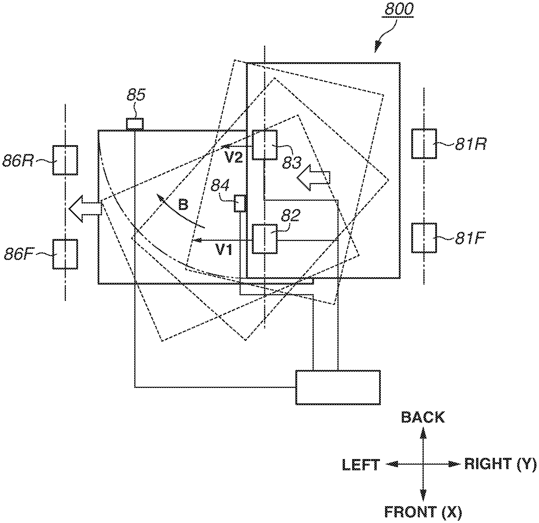
[0096] FIG. 13 is a diagram illustrating a top view of the change conveyance unit 800. To change the orientation of the sheet S by substantially 90 degrees, the change conveyance unit 800 changes the orientation of the sheet S using two rollers configured to rotate at speeds different from each other.
[0097] Roller pairs 81F and 81R serving as the first conveyance roller pairs receive the sheets S conveyed from the feeding unit 300. The orientation of the sheet S is changed by substantially 90 degrees using a roller pair 82 and a roller pair 83 that are disposed downstream of the roller pairs 81F and 81R and that serve as the second conveyance unit. While the speed of the roller pair 82 can be adjusted (changed), the speed of the roller pair 83 is constant. That is, the second conveyance unit includes a plurality of conveyance members provided in a direction intersecting the conveyance direction, and the conveyance speed of one of the conveyance members (the roller pair 82) can be changed to a speed different from the conveyance speed of another conveyance member (the roller pair 83). Alternatively, the speed of the roller pair 83 may be adjusted (changed) while the speed of the roller pair 82 is constant, or the respective speeds of the roller pair 82 and the roller pair 83 may be adjusted (changed) independently of each other. Any roller the speed of which is adjustable is controlled as appropriate by a controller C.
[0098] The sheet S that has been conveyed in the landscape orientation by the conveyance roller pairs 81R and 81F serving as the first conveyance unit is then fed into the roller pairs 82 and 83. In this process, a speed V1 of the roller pair 82 is controlled by the controller C to a speed equal to a speed V2 of the roller pair 83, that is, V1=V2. When a change start sensor 84 detects the leading end of the sheet S that has been conveyed in the landscape orientation, the speed V1 of the roller pair 82 is controlled by the controller C to a speed faster than the speed V2 of the roller pair 83, that is, V1>V2. That is, the rotation speeds of the roller pairs 82 and 83 are controlled by the controller C so that the sheet conveyance speeds are different between the roller pairs.
[0099] Since the sheet S is conveyed faster in one side (the trailing end side in the front-back direction X) conveyed by the roller pair 82 than in the other side (the leading end side in the front-back direction X) conveyed by the roller pair 83, the sheet S pivots in the arrow B direction and the orientation of the sheet S is changed. Subsequently, when the trailing end of the sheet S of which orientation is changed from the landscape orientation to the portrait orientation is detected by a change end sensor 85, it is determined that the orientation of the sheet S is changed to the portrait orientation, and the speed V1 of the roller pair 82 is controlled by the controller C to the speed equal to the speed V2 of the roller pair 83, that is, V1=V2.
[0100] The sheet S of which orientation is changed to the portrait orientation is conveyed by the roller pairs 82 and 83 and is fed into roller pair 86F and 86R. The sheet S in the portrait orientation is conveyed by the roller pairs 86F and 86R to the sheet interval adjusting unit 600.
[0101] The speed V1 of the roller pair 82 and the speed V2 of the roller pair 83 when the conveyance orientation of the sheet S is changed are individually controlled so that the orientation change of the sheet S is completed and the change end sensor 85 detects the completion before the sheet S reaches the roller pairs 86F and 86R.
[0102] As described above, the change conveyance unit 800 can change the conveyance orientation of the sheet S without having the abutment wall 53 included in the change conveyance unit 500.
[0103] The change conveyance apparatus 400 according to the first example embodiment may be configured to be attachable to and detachable from the printer 100 and the feeding unit 300 as illustrated in FIG. 19 and FIG. 20. FIGS. 19 and 20 illustrate a positioning pin 38b and a locking lever 39 serving as a locking member, which are disposed on the feeding unit 300. A positioning hole 38a, a locking lever 43 serving as a locking member, and a positioning pin 41b, are disposed on the change conveyance apparatus 400. A positioning hole 41a is disposed on the printer 100. When the change conveyance apparatus 400 is attached to the printer 100, the positions of the change conveyance apparatus 400 and the printer 100 are fixed relative to each other with the positioning pin 41b on the change conveyance apparatus 400 interlocking with the positioning hole 41a provided on the printer 100.
[0104] When the feeding unit 300 is attached to the change conveyance apparatus 400, the positions of the feeding unit 300 and the change conveyance apparatus 400 are fixed relative to each other with the positioning hole 38a on the change conveyance apparatus 400 interlocking with the positioning pin 38b on the feeding unit 300.
[0105] The locking lever 39 on the feeding unit 300 is connected to the change conveyance apparatus 400, and the locking lever 43 on the change conveyance apparatus 400 is connected to the printer. The user can fix the apparatuses to each other using the locking lever 39 and the locking lever 43. FIG. 20 illustrates a state in which the feeding unit 300 and the change conveyance apparatus 400 are fixed to each other. The locking lever 39 on the feeding unit 300 is configured to turn about a support 39F in the arrow R direction. When the locking lever 39 is brought into a state indicated by a solid line from a state indicated by a dotted line as illustrated in FIG. 20, the feeding unit 300 and the change conveyance apparatus 400 are fixed to each other. A locking mechanism between the change conveyance apparatus 400 and the printer 100 has the same configuration as described above.
[0106] The change conveyance apparatus 400 may be configured as a part of the feeding unit 300 or may be configured to be attachable to and detachable from each of the feeding unit 300 and the printer 100 as in FIGS. 19 and 20.
[0107] In the configurations described in the first example embodiment, the sheet S is conveyed in one direction when the sheet S is conveyed in the portrait orientation by the change conveyance apparatus 400, 400B, or 400C. A second example embodiment employs a different manner for conveying the sheet S in the portrait orientation. The same components as those in the first example embodiment are described using the same reference signs as in the first example embodiment.
[0108] In the second example embodiment, the conveyance orientation of the sheet S is changed using two rollers configured to rotate at speeds different from each other as in the change conveyance apparatus 400C provided in an modification example of the first example embodiment. Specifically, instead of making a U-turn in the change conveyance unit, the sheet S makes a switchback movement using a flapper. The conveyance direction after the switchback movement is opposite to a first sheet conveyance direction in which the sheet S has been fed into the change conveyance apparatus 400.
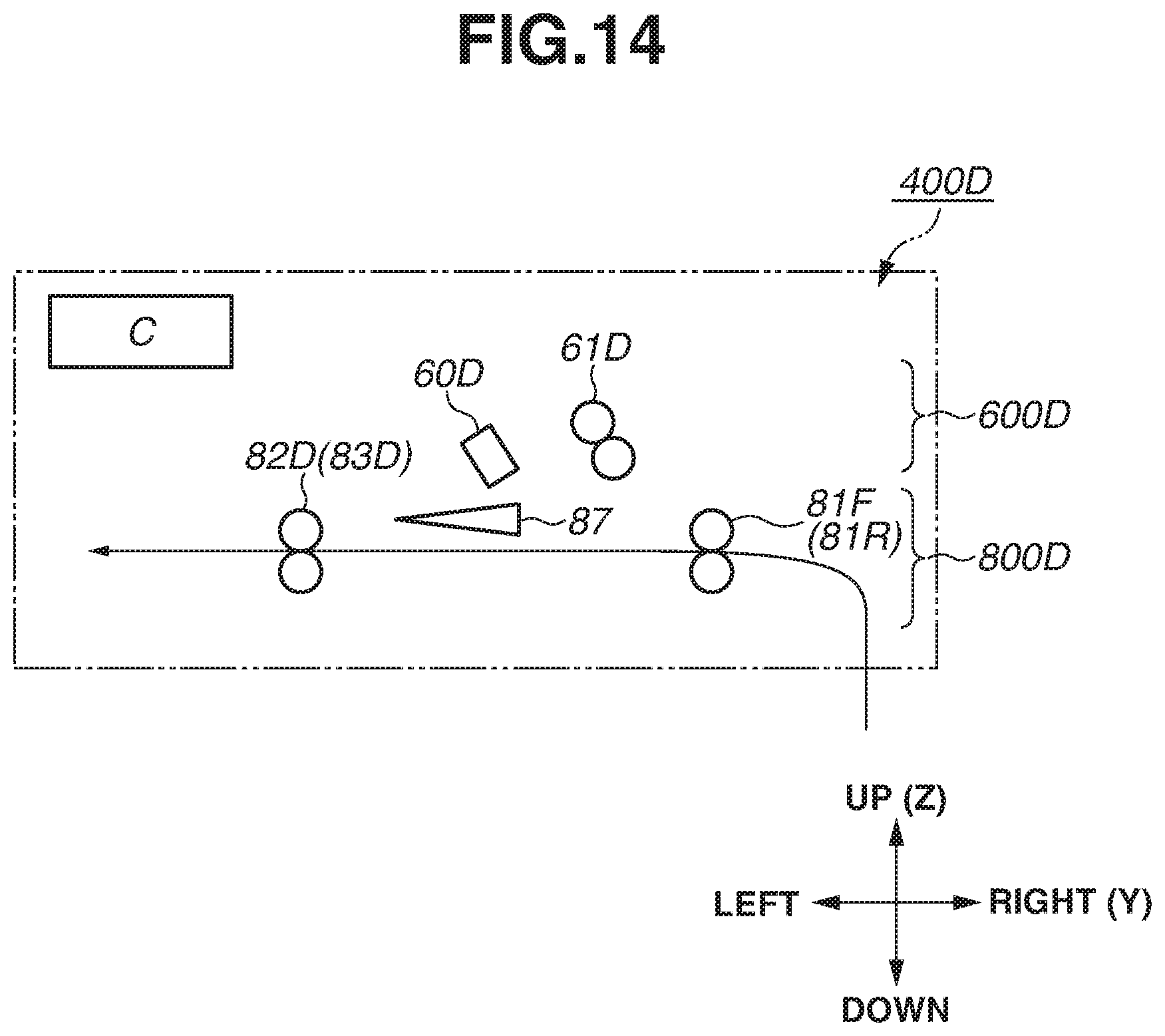
[0109] FIG. 14 is a schematic cross-sectional view illustrating a change conveyance apparatus 400D according to the second example embodiment.
[0110] The change conveyance unit 800D includes the roller pairs 81F and 81R, which are the first conveyance unit, and roller pairs 82D and 83D serving as the second conveyance unit. The roller pairs 81F and 81R are conveyance roller pairs that receive the sheets S conveyed in the landscape orientation from the feeding unit 300.
[0111] A flapper 87 provided in the change conveyance unit 800D is rotatory moves by a drive source from such as a solenoid (not illustrated), and the flapper 87 rotates when the drive source is controlled by the controller C.
[0112] The conveyance orientation of the sheet S is changed by substantially 90 degrees using a roller pair 82D and a roller pair 83D that are disposed downstream of the roller pairs 81F and 81R. The speeds of the roller pairs 82D and 83D can be adjusted (changed), and the roller pairs 82D and 83D can be reversely rotated. When the sheet S is delivered into the change conveyance unit 800D, the leading end of the flapper 87 is held in an orientation (for example, leftward in the left-right direction Y as illustrated in FIG. 14) that keeps the flapper 87 from interrupting the sheet conveyance between the roller pairs 81F and 81R and the roller pairs 82D and 83D.
[0113] FIG. 15 is a schematic cross-sectional view illustrating the switchback movement of the sheet S conveyed by the change conveyance apparatus 400D. The change conveyance apparatus 400D conveys, to the printer 100, the sheet S that has been changed to the portrait orientation by the switchback operation in the change conveyance unit 800D. During the conveyance, the end of the flapper 87 is changed into an orientation as illustrated in FIG. 15 and held. By a position change in the end of the flapper 87, the sheet S is guided by the flapper 87 and conveyed. The sheet S is thus fed into a sheet interval adjusting unit 600D. The leading end of the sheets S conveyed by the roller pairs 82D and 83D are detected by the sheet S leading end detecting sensor 60D in the sheet interval adjusting unit 600D, whereby information on the sheet intervals is acquired. The sheet intervals are adjusted as needed by rotation speed adjustment of a roller pair 61D, and the sheets S are discharged to the printer 100.
[0114] With the above-described configuration, the orientation of the sheets S can be changed from the landscape orientation to the portrait orientation, the overall height of the image forming system can be downsized.
[0115] In a third example embodiment, a post-processing apparatus is attached to an image forming apparatus is described. The same components as those in the first example embodiment are described using the same reference signs as in the first example embodiment.
[0116] FIG. 16 is a perspective view illustrating an image forming system according to the third example embodiment, FIG. 17 is a cross-sectional view illustrating the image forming system. The configuration of the third example embodiment is described using FIG. 17.
[0117] A sheet discharge device 1100 is arranged on the printer 100 in the up-down direction Z, a post-processing apparatus 1200 is arranged on the left of the printer 100 in the left-right direction Y. The sheets on which images are formed by the printer 100 are conveyed from the discharge roller pair 20 in the printer 100 to the conveyance roller 111 in the sheet discharge device 1100. The sheets S are conveyed from the conveyance roller 111 to the conveyance roller 121 in the post-processing apparatus 1200.
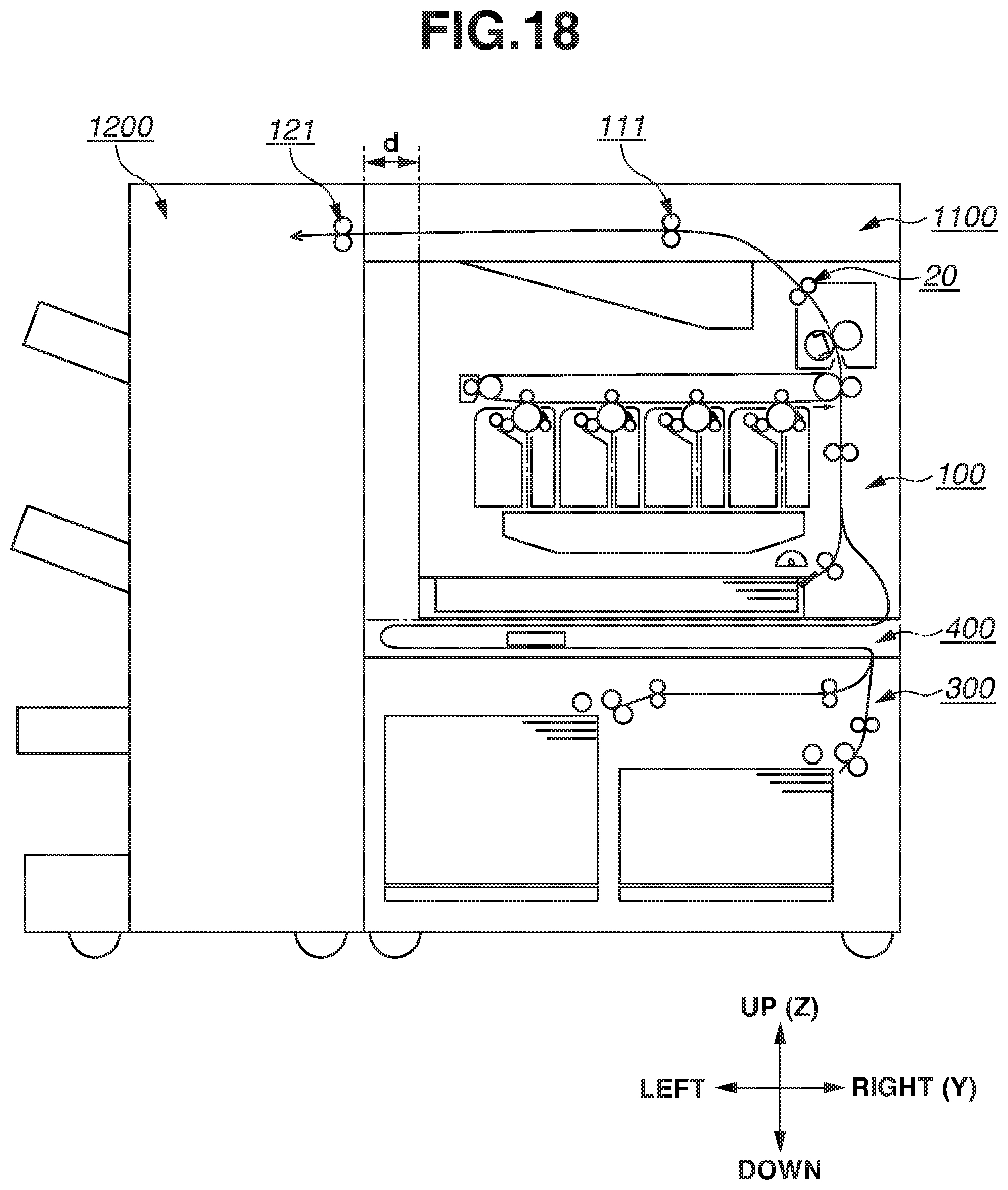
[0118] As illustrated in FIG. 17, in a case where the post-processing apparatus 1200 is attached on the left of the printer 100 in the left-right direction Y, the printer 100, the feeding unit 300, and the change conveyance apparatus 400 may be aligned along the left side in the left-right direction Y. This is because the conveyance distance from the printer 100 to the post-processing apparatus 1200 is shorter by a length of d than the conveyance distance of the case in which the printer 100, the feeding unit 300, and the change conveyance apparatus 400 are aligned along the right side in the left-right direction Y as illustrated in FIG. 18. Therefore, the configuration illustrated in FIG. 17 has higher productivity than the configuration illustrated in FIG. 18.
[0119] Alternatively, in a case where the post-processing apparatus 1200 is on the right of the printer 100 in the left-right direction Y, the feeding unit 300, and the change conveyance apparatus 400 may be aligned along the right side.
[0120] With the above configuration, the productivity can be enhanced when the post-processing apparatus 1200 is attached to the printer 100.
[0121] In the first example embodiment, the rotational axis of a rotator included in the second conveyance unit is substantially parallel to the rotational axis of a rotator included in the first conveyance unit. In a fourth example embodiment, the rotational axis of a rotator included in the second conveyance unit intersects the rotational axis of a rotator included in the first conveyance unit. The same components as those in the first example embodiment are described using the same reference signs as in the first example embodiment.
[0122] FIG. 22 is a top view illustrating the change conveyance unit 800 in the fourth example embodiment. A change conveyance roller pair 520 illustrated in FIG. 22 (one rotator among two rotators, a change conveyance roller (driven roller) 520b in FIG. 22) serves as the second conveyance unit and is disposed in a direction with which a rotational axis 520i of the change conveyance roller pair 520 intersects the rotational axes (rotational axis 55i and rotational axis 51i) of the other conveyance units. The change conveyance roller 520b is a rotation roller that is driven by a change conveyance roller 520a (not illustrated) to rotate. The rotational axis 520i of the change conveyance roller 520b is inclined from the other rotational axes (rotational axis 55i and rotational axis 51i) by about 5 degrees.
[0123] During the sheet orientation change, a turning moment of which radius is a line La from the abutment point 54 to the center of the nip of the change conveyance roller pair 520 is generated. Accordingly, conveyance force Lb in a direction perpendicular to the line La is generated by the turning moment. Consequently, after the completion of the sheet orientation change, the sheet is conveyed in the direction of the conveyance force Lb. Therefore, the sheet is conveyed while moving away from the guide surface 56. In the present example embodiment, the driven roller 520b is inclined toward the guide surface 56. By inclining the driven roller 520b, conveyance force Lc that makes the sheet move toward the guide surface 56 is generated. Consequently, upon completion of the sheet orientation change, the sheet is conveyed along the guide surface 56 leftward in the left-right direction Y and fed into the drawing roller pairs 55F and 55R in the downstream side.
[0124] In the present example embodiment, the driven roller 520b is inclined by 5 degrees. However, the inclination is not limited to this angle. the inclination may be set to an angle with which a sheet can be conveyed along the guide surface 56 against the conveyance Lb. Therefore, as in the first example embodiment, the configuration according to the fourth example embodiment can simplify the configuration of the change conveyance unit 800 and can ensure the sheet conveyance orientation change.
[0125] While the present disclosure has been described with reference to example embodiments, it is to be understood that the disclosure is not limited to the disclosed example embodiments. The scope of the following claims is to be accorded the broadest interpretation so as to encompass all such modifications and equivalent structures and functions.
[0126] This application claims the benefit of Japanese Patent Applications No. 2019-170515, filed Sep. 9, 2019, No. 2018-228337, filed Dec. 5, 2018, No. 2018-221731, filed Nov. 27, 2018, and No. 2018-221732, filed Nov. 27, 2018, which are hereby incorporated by reference herein in their entirety.
* * * * *
D00000
D00001
D00002
D00003
D00004
D00005
D00006
D00007
D00008
D00009
D00010
D00011
D00012

D00013

D00014
D00015

D00016

D00017

D00018
D00019

D00020

D00021

D00022

XML
uspto.report is an independent third-party trademark research tool that is not affiliated, endorsed, or sponsored by the United States Patent and Trademark Office (USPTO) or any other governmental organization. The information provided by uspto.report is based on publicly available data at the time of writing and is intended for informational purposes only.
While we strive to provide accurate and up-to-date information, we do not guarantee the accuracy, completeness, reliability, or suitability of the information displayed on this site. The use of this site is at your own risk. Any reliance you place on such information is therefore strictly at your own risk.
All official trademark data, including owner information, should be verified by visiting the official USPTO website at www.uspto.gov. This site is not intended to replace professional legal advice and should not be used as a substitute for consulting with a legal professional who is knowledgeable about trademark law.