Image Reading Apparatus And Image Forming System
MAEYAMA; Yuichiro
U.S. patent application number 16/671521 was filed with the patent office on 2020-05-28 for image reading apparatus and image forming system. This patent application is currently assigned to Ricoh Company, Ltd.. The applicant listed for this patent is Yuichiro MAEYAMA. Invention is credited to Yuichiro MAEYAMA.
| Application Number | 20200165088 16/671521 |
| Document ID | / |
| Family ID | 70771347 |
| Filed Date | 2020-05-28 |


View All Diagrams
| United States Patent Application | 20200165088 |
| Kind Code | A1 |
| MAEYAMA; Yuichiro | May 28, 2020 |
IMAGE READING APPARATUS AND IMAGE FORMING SYSTEM
Abstract
In at least one embodiment of this disclosure, there is provided an image reading apparatus that includes a reader, an upstream reading conveyance rotator pair, at least one upstream conveyance rotator pair, and an upstream separator. The reader reads a detection target image on a sheet. The upstream reading conveyance rotator pair is disposed upstream from the reader in a sheet conveyance direction to convey the sheet. The upstream conveyance rotator pair is disposed upstream from the upstream reading conveyance rotator pair in the sheet conveyance direction to convey the sheet toward the upstream reading conveyance rotator pair. The upstream separator causes one rotator of the upstream conveyance rotator pair to be contacted against and separated from another rotator of the upstream conveyance rotator pair.
| Inventors: | MAEYAMA; Yuichiro; (Kanagawa, JP) | ||||||||||
| Applicant: |
|
||||||||||
|---|---|---|---|---|---|---|---|---|---|---|---|
| Assignee: | Ricoh Company, Ltd. Tokyo JP |
||||||||||
| Family ID: | 70771347 | ||||||||||
| Appl. No.: | 16/671521 | ||||||||||
| Filed: | November 1, 2019 |
| Current U.S. Class: | 1/1 |
| Current CPC Class: | B65H 2511/22 20130101; B65H 29/125 20130101; B65H 2511/512 20130101; B65H 5/062 20130101; B65H 2801/06 20130101; B65H 2404/144 20130101; B65H 7/02 20130101; B65H 7/14 20130101; B65H 2511/224 20130101; G03G 15/00 20130101; B65H 29/20 20130101; B41J 13/00 20130101; B65H 2511/224 20130101; B65H 2220/02 20130101; B65H 2511/512 20130101; B65H 2220/01 20130101; B65H 2511/22 20130101; B65H 2220/01 20130101; B65H 2511/22 20130101; B65H 2220/01 20130101; B65H 2220/11 20130101 |
| International Class: | B65H 7/02 20060101 B65H007/02; B65H 5/06 20060101 B65H005/06; B65H 29/20 20060101 B65H029/20 |
Foreign Application Data
| Date | Code | Application Number |
|---|---|---|
| Nov 27, 2018 | JP | 2018-221384 |
Claims
1. An image reading apparatus comprising: a reader configured to read a detection target image on a sheet; an upstream reading conveyance rotator pair disposed upstream from the reader in a sheet conveyance direction and configured to convey the sheet; at least one upstream conveyance rotator pair disposed upstream from the upstream reading conveyance rotator pair in the sheet conveyance direction and configured to convey the sheet toward the upstream reading conveyance rotator pair; and an upstream separator configured to cause one rotator of the upstream conveyance rotator pair to be contacted against and separated from another rotator of the upstream conveyance rotator pair.
2. The image reading apparatus according to claim 1, further comprising: a downstream reading conveyance rotator pair disposed downstream from the reader in the sheet conveyance direction and configured to convey the sheet; at least one downstream conveyance rotator pair disposed downstream from the downstream reading conveyance rotator pair in the sheet conveyance direction and configured to receive the sheet conveyed from the downstream reading conveyance rotator pair to convey the sheet downstream; and a downstream separator configured to cause one rotator of the downstream conveyance rotator pair to he contacted against and separated from another rotator of the downstream conveyance rotator pair.
3. The image reading apparatus according to claim 2, further comprising a downstream reading conveyance separator configured to cause one rotator of the downstream reading conveyance rotator pair to be contacted against and separated from another rotator of the downstream reading conveyance rotator pair, wherein the downstream reading conveyance rotator pair is separated if a distance Lm1 from a leading end of the sheet to an upstream end of the detection target image in the sheet conveyance direction is longer than a distance L2 from the reading position in which reading is performed by the reader to the downstream reading conveyance rotator pair.
4. The image reading apparatus according to claim 3, wherein the downstream reading conveyance rotator pair is separated before the leading end of the sheet reaches the downstream reading conveyance rotator pair.
5. The image reading apparatus according to claim 3, wherein the image reading apparatus has a relation of Lmin>(Lm1+L1), where L1 is a distance between the upstream reading conveyance rotator pair and the reading position in which reading is performed by the reader, Lm1 is the distance Lm1, and Lmin is a minimum sheet length passable inside the image reading apparatus.
6. The image reading apparatus according to claim 2, further comprising a plurality of downstream conveyance rotator pairs including the at least one downstream conveyance rotator pair, and wherein, out of the plurality of downstream conveyance rotator pairs, a downstream conveyance rotator pair having a shorter distance to the reading position than a maximum length of the sheet to be conveyed is separated.
7. The image reading apparatus according to claim 2, further comprising an upstream reading conveyance separator configured to cause one rotator of the upstream reading conveyance rotator pair to be contacted against and separated from another rotator of the upstream reading conveyance rotator pair, wherein the upstream reading conveyance rotator pair is separated if a distance Lm2 from a trailing end of the sheet to a downstream end of the detection target image in the sheet conveyance direction is longer than a distance L1 from the upstream reading conveyance rotator pair to the reading position in which reading is performed by the reader.
8. The image reading apparatus according to claim 7, wherein the upstream reading conveyance rotator pair is separated before the detection target image reaches the reading position in which reading is performed by the reader.
9. The image reading apparatus according to claim 7, wherein the image reading apparatus has a relation of Lmin>(Lm2+L2), where L2 is a distance between the reading position in which reading is performed by the reader and the downstream reading conveyance rotator pair, Lm2 is the distance Lm2, and Lmin is a minimum length of the sheet.
10. The image reading apparatus according to claim 2, wherein the image reading apparatus has a relation of L2>V.times.(T3+T4), where L2 is a distance between the downstream reading conveyance rotator pair and the reading position in which reading is performed by the reader, T3 is a duration of time from when a trailing end of the sheet reaches the reading position to when contact between the downstream conveyance rotator pair begins, T4 is a duration of time from the beginning of the contact to end of the contact, and V is a sheet conveyance speed.
11. The image reading apparatus according to claim 10, wherein the image reading apparatus has a relation of T3+T4>0, where -T3 is a duration of time from when the contact between the downstream conveyance rotator pair begins before a trailing end of the sheet reaches the reading position to when the trailing end of the sheet reaches the reading position after the contact begins.
12. The image reading apparatus according to claim 1, wherein the upstream conveyance rotator pair is separated after a leading end of the sheet reaches the upstream reading conveyance rotator pair and before the leading end of the sheet reaches a reading position in which reading is performed by the reader.
13. The image reading apparatus according to claim 1, wherein the image reading apparatus is configured so that L1>V.times.(T1+T2), where L1 is a distance between the upstream reading conveyance rotator pair and the reading position in which reading is performed by the reader, T1 is a duration of time from when a leading end of the sheet P reaches the upstream reading conveyance rotator pair to separation of the upstream conveyance rotator pair begins, T2 is a duration of time from the beginning of the separation to end of the separation, and V is a conveyance speed of the sheet.
14. The image reading apparatus according to claim 1, further comprising a plurality of upstream conveyance rotator pairs including the at least one upstream conveyance rotator pair, and wherein, out of the plurality of upstream conveyance rotator pairs, an upstream conveyance rotator pair having a shorter distance to the reading position than a maximum length of the sheet to be conveyed is separated.
15. An image forming system comprising: the image reading apparatus according to claim 1; and an image forming apparatus configured to form an image on the sheet.
16. An image reading apparatus comprising: a reader configured to read a detection target image formed on a sheet; a downstream reading conveyance rotator pair disposed downstream from the reader in a sheet conveyance direction and configured to convey the sheet; at least one downstream conveyance rotator pair disposed downstream from the downstream reading conveyance rotator pair in the sheet conveyance direction and configured to receive the sheet conveyed from the downstream reading conveyance rotator pair to convey the sheet downstream; and a downstream separator configured to cause one rotator of the downstream conveyance rotator pair to be contacted against and separated from another rotator of the downstream conveyance rotator pair.
17. The image reading apparatus according to claim 16, further comprising a downstream reading conveyance separator configured to cause one rotator of the downstream reading conveyance rotator pair to be contacted against and separated from another rotator of the downstream reading conveyance rotator pair, wherein the downstream reading conveyance rotator pair is separated if a distance Lm1 from a leading end of the sheet to an upstream end of the detection target image in the sheet conveyance direction is longer than a distance L2 from the reading position in which reading is performed by the reader to the downstream reading conveyance rotator pair.
18. The image reading apparatus according to claim 17, wherein the downstream reading conveyance rotator pair is separated before the leading end of the sheet reaches the downstream reading conveyance rotator pair.
19. The image reading apparatus according to claim 17, further comprising a plurality of downstream conveyance rotator pairs including the at least one downstream conveyance rotator pair, and wherein, out of the plurality of downstream conveyance rotator pairs, a downstream conveyance rotator pair having a shorter distance to the reading position than a maximum length of the sheet to be conveyed is separated.
20. An image forming system comprising: the image reading apparatus according to claim 16; and an image forming apparatus configured to form an image on the sheet.
Description
CROSS-REFERENCE TO RELATED APPLICATION
[0001] This patent application is based on and claims priority pursuant to 35 U.S.C. .sctn. 119 to Japanese Patent Application No. 2018-221384, filed on Nov. 27, 2018, in the Japan Patent Office, the entire disclosure of which is hereby incorporated by reference herein.
BACKGROUND
Technical Field
[0002] Exemplary aspects of the present disclosure relate to an image reading apparatus and an image forming system incorporating the image reading apparatus.
Related Art
[0003] Among image reading apparatuses, some are designed to read a detection target image imprinted on a sheet.
[0004] Conventionally, reading apparatuses designed to maintain a constant sheet conveyance speed employ an arrangement in which an upstream conveyance roller pair and a downstream conveyance roller pair for conveying a sheet to an image reader are respectively provided upstream and downstream of the image reader. The sheet is conveyed by the upstream conveyance roller pair in a state in which the pair of downstream conveyance rollers is separated, and an image on the sheet is read by the image reader. When a leading end of the sheet reaches the downstream conveyance roller pair, the upstream conveyance roller pair is separated and the sheet is conveyed by the downstream conveyance roller pair to maintain a constant sheet conveyance speed.
SUMMARY
[0005] In an embodiment of this disclosure, there is provided an improved image reading apparatus that includes a reader, an upstream reading conveyance rotator pair, at least one upstream conveyance rotator pair, and an upstream separator. The reader reads a detection target image on a sheet. The upstream reading conveyance rotator pair is disposed upstream from the reader in a sheet conveyance direction to convey the sheet. The upstream conveyance rotator pair is disposed upstream from the upstream reading conveyance rotator pair in the sheet conveyance direction to convey the sheet toward the upstream reading conveyance rotator pair. The upstream separator causes one rotator of the upstream conveyance rotator pair to be contacted against and separated from another rotator of the upstream conveyance rotator pair.
[0006] In another embodiment of the present disclosure, there is provided an improved image reading apparatus that includes a reader, a downstream reading conveyance rotator pair, at least one downstream conveyance rotator pair, and a downstream separator. The reader reads a detection target image formed on a sheet. The downstream reading conveyance rotator pair is disposed downstream from the reader in a sheet conveyance direction to convey the sheet. The downstream conveyance rotator pair is disposed downstream from the downstream reading conveyance rotator pair in the sheet conveyance direction. The downstream conveyance rotator pair receives the sheet conveyed from the downstream reading conveyance rotator pair to convey the sheet downstream. The downstream separator causes one rotator of the downstream conveyance rotator pair to be contacted against and separated from another rotator of the downstream conveyance rotator pair.
[0007] In still another embodiment of the present disclosure, there is provided an image forming system including the image reading apparatus according to any of the above-described embodiments and an image forming apparatus that forms an image on the sheet.
BRIEF DESCRIPTION OF THE DRAWINGS
[0008] The aforementioned and other aspects, features, and advantages of the present disclosure are better understood by reference to the following detailed description when considered in connection with the accompanying drawings, wherein:
[0009] FIG. 1 is a schematic diagram illustrating an image reading apparatus according to a first embodiment;
[0010] FIGS. 2A, 2B, and 2C are schematic diagrams illustrating a reading operation according to the embodiment;
[0011] FIGS. 3A, 3B, and 3C are schematic diagrams illustrating the reading operation according to the embodiment;
[0012] FIG. 4 is a schematic diagram illustrating an image reading apparatus according to a second embodiment;
[0013] FIGS. 5A and 5B are schematic diagrams illustrating a reading operation according to the second embodiment;
[0014] FIG. 6 is a schematic diagram illustrating an image reading apparatus according to a third embodiment;
[0015] FIG. 7 is a schematic diagram illustrating an image reading apparatus according to a fourth embodiment;
[0016] FIGS. 8A and 8B are schematic diagrams illustrating a reading operation according to the fourth embodiment;
[0017] FIG. 9 is a schematic diagram illustrating an image reading apparatus according to a fifth embodiment;
[0018] FIG. 10 is a diagram illustrating one example of an image forming system;
[0019] FIG. 11 is a diagram illustrating arrangement of a reading device and a position reference member in a detection device;
[0020] FIG. 12 is a diagram illustrating one example of a pattern as a detection mark that is formed on a sheet for image position adjustment;
[0021] FIG. 13 is a diagram illustrating types of image correction; and
[0022] FIG. 14 is a diagram illustrating one example of an upstream separator of an upstream conveyance rotator pair (a conveyance roller pair) of the image reading apparatus.
[0023] The accompanying drawings are intended to depict embodiments of the present disclosure and should not be interpreted to limit the scope thereof. The accompanying drawings are not to be considered as drawn to scale unless explicitly noted.
DETAILED DESCRIPTION
[0024] In describing embodiments illustrated in the drawings, specific terminology is employed for the sake of clarity. However, the disclosure of this patent specification is not intended to be limited to the specific terminology so selected and it is to be understood that each specific element includes all technical equivalents that have the same function, operate in a similar manner and achieve similar results.
[0025] Referring now to the drawings, embodiments of the present disclosure are described below In the drawings for explaining the following embodiments, the same reference codes are allocated to elements (members or components) having the same function or shape and redundant descriptions thereof are omitted below.
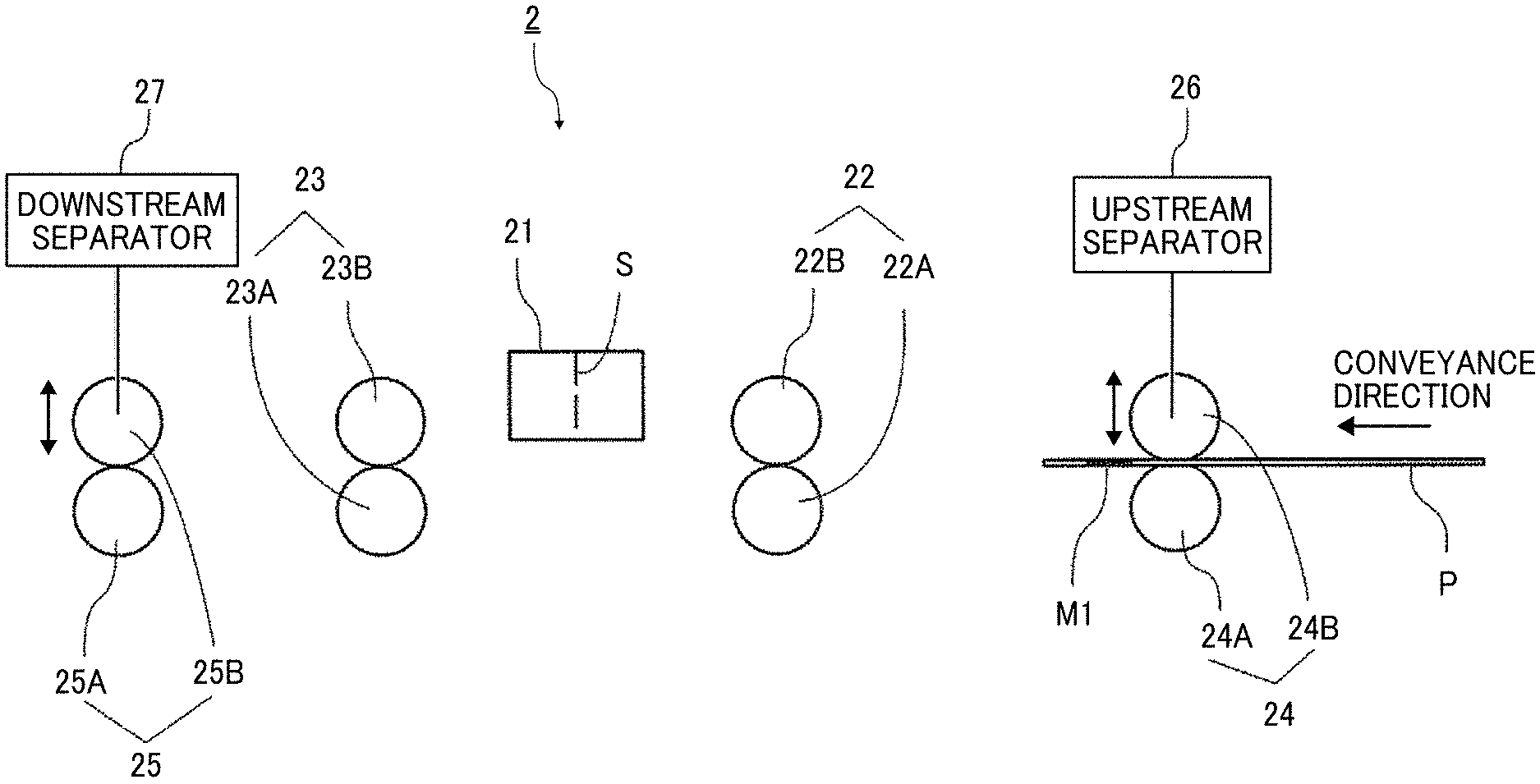
[0026] FIG. 1 schematically illustrates an image reading apparatus 2 according to a first embodiment.
[0027] The image reading apparatus 2 includes a reader 21 that reads a detection mark M (e.g., a detection mark M1 on a leading end of a sheet in FIG. 1) as a detection target image on a sheet P.
[0028] The image reading apparatus 2 also includes an upstream reading conveyance roller pair 22 (22A, 22B) as an upstream reading conveyance rotator pair for conveying the sheet P, and a downstream reading conveyance roller pair 23 (23A, 23B) as a downstream reading conveyance rotator pair for conveying the sheet P. The upstream reading conveyance roller pair 22 is disposed upstream from the reader 21 in a sheet conveyance direction, whereas the downstream reading conveyance roller pair 23 is disposed downstream from the reader 21 in the sheet conveyance direction.
[0029] The image reading apparatus 2 includes an upstream conveyance roller pair 24 (24A, 24B) as an upstream conveyance rotator pair. The upstream conveyance roller pair 24 is disposed upstream from the upstream reading conveyance roller pair 22 in the sheet conveyance direction to convey the sheet P toward the upstream reading conveyance roller pair 22. In FIG. 1, the image reading apparatus 2 includes at least one upstream conveyance roller pair 24. However, a plurality of upstream conveyance roller pairs 24 may be disposed along the sheet conveyance direction.
[0030] The upstream conveyance roller pair 24 (24A, 24B) is disposed such that one conveyance roller (a driven roller) 24B can be contacted against and separated from the other conveyance roller (a drive roller) 24A. The image reading apparatus 2 includes an upstream separator 26 that causes the driven roller 24B of the upstream conveyance roller pair 24 to be contacted against and separated from the drive roller 24A.
[0031] Moreover, the image reading apparatus 2 includes a downstream conveyance roller pair 25 (25A, 25B) as a downstream conveyance rotator pair. The downstream conveyance roller pair 25 is disposed downstream from the downstream reading conveyance roller pair 23 in the sheet conveyance direction. The downstream conveyance roller pair 25 receives the sheet P conveyed from the downstream reading conveyance roller pair 23 to convey the received sheet P downstream. In FIG. 1, the image reading apparatus 2 includes at least one downstream conveyance roller pair 25. However, a plurality of downstream conveyance roller pair 25 may be disposed along the sheet conveyance direction.
[0032] The downstream conveyance roller pair 25 (25A, 25B) is disposed such that one conveyance roller (a driven roller) 25B can be contacted against and separated from the other conveyance roller (a drive roller) 25A. The image reading apparatus 2 includes a downstream separator 27 that causes the driven roller 25B of the downstream conveyance roller pair 25 to be contacted against and separated from the drive roller 25A.
[0033] A reading operation according to the present embodiments described with reference to FIGS. 2A through 3C.
[0034] As illustrated in FIG. 2A, when a detection mark M1 on a sheet P is read, the upstream conveyance roller pair 24 conveys the sheet P toward the upstream reading conveyance roller pair 22 at a conveyance speed V. As illustrated in FIG. 2B, the upstream reading conveyance roller pair 22 conveys the sheet P to a reading position S at which reading is performed by the reader 21.
[0035] Herein, after the sheet P reaches the upstream reading conveyance roller pair 22, the driven roller 24B of the upstream conveyance roller pair 24 is separated from the drive roller 24A by the upstream separator 26 before a leading end of the sheet P reaches the reading position S at which reading is performed by the reader 21.
[0036] Herein, the image reading apparatus 2 is configured so that:
L1>V.times.(T1+T2),
[0037] where T1 is a duration of time from when the sheet P reaches the upstream reading conveyance roller pair 22 to separation of the driven roller 24B begins, T2 is a duration of time (separation time) from the beginning to the end of the separation of the driven roller 24B, V is a conveyance speed of the sheet P, and L1 is a distance between the upstream reading conveyance roller pair 22 and the reading position S.
[0038] In such a case, the distance L1 is preferably set in consideration of a margin to reduce fluctuations in the speed due to shock generated at the time of separation of the driven roller 24B.
[0039] If a plurality of upstream conveyance roller pairs 24 is disposed, all of the driven rollers 2413 of the upstream conveyance roller pairs 24 positioned upstream from the upstream reading conveyance roller pair 22 by a maximum length of the sheet P or greater are preferably separated.
[0040] Herein, as illustrated in FIG. 2C, the sheet P is conveyed to the reader 21 by only the upstream reading conveyance roller pair 22, and thus the upstream reading conveyance roller pair 22 and the upstream conveyance roller pair 24 can be prevented from pulling against each other via the sheet P.
[0041] Accordingly, the sheet P can be conveyed with high accuracy, and coordinates of a detection mark in the conveyance direction can be detected with high accuracy.
[0042] Subsequently, when a detection mark M2 in a trailing end of the sheet P is to be read, as illustrated in FIG. 3A, the driven roller 25B of the downstream conveyance roller pair 25 is separated from the drive roller 25A before the detection mark M2 in the trailing end of the sheet P reaches the reading position S at which reading is performed by the reader 21.
[0043] Herein, if a plurality of downstream conveyance roller pairs 25 is disposed, all of the driven rollers 25B of the downstream conveyance roller pairs 25 positioned downstream from the reading position S by a maximum length of the sheet P or greater are preferably separated.
[0044] Herein, as illustrated in FIG. 3B, the sheet P is conveyed to the reader 21 by only the downstream reading conveyance roller pair 23, and thus the downstream reading conveyance roller pair 23 and the downstream conveyance roller pair 25 can be prevented from pulling against each other via the sheet P.
[0045] Accordingly, the sheet P can be conveyed with high accuracy, and coordinates of the detection mark in the conveyance direction can be detected with high accuracy.
[0046] Then, as illustrated in FIG. 3C, when the reading of the trailing end of the sheet P is finished, the driven roller 25B of the downstream conveyance roller pair 25 is pressed against (contacts) the drive roller 25A.
[0047] Herein, the driven roller 25B and the drive roller 25A need to be pressed against each other before the trailing end of the sheet P passes through the downstream reading conveyance roller pair 23.
[0048] Thus, the image reading apparatus 2 is configured so that:
L2>V.times.(T3+T4),
[0049] where L2 is a distance between the downstream reading conveyance roller pair 23 and the reading position S, T3 is a duration of time from when a trailing end of the sheet P reaches the reading position S to when contact between the rollers 25A and 25B of the downstream conveyance roller pair 25 is started, T4 is time that is needed for the rollers 25A and 25B to contact (press against) each other, and V is a sheet conveyance speed.
[0050] Accordingly, the sheet P can be conveyed by the downstream conveyance roller pair 25 before the trailing end of the sheet P passes through the downstream reading conveyance roller pair 23, and high reading accuracy can be obtained.
[0051] Alternatively, contact between the rollers 25A and 25B of the downstream conveyance roller pair 25 may be started before a trailing end of the sheet P reaches the reading position S. In such a case, the image reading apparatus 2 has the following relation:
T3+T4>0,
[0052] where T3 is a negative value of T3 that is a duration of time from when contact between the rollers 25A and 25B is started to when the trailing end of the sheet P reaches the reading position S.
[0053] That is, although the time 13 can be a negative value, the relation is set to T3+T4>0 such that a sheet conveyance speed does not fluctuate due to contact between the rollers while the trailing end of the sheet P is being read.
[0054] Accordingly, a detection target image on the sheet can be read with high accuracy.
[0055] FIG. 4 is a schematic diagram illustrating an image reading apparatus 2 according to a second embodiment.
[0056] In the present embodiment, a downstream reading conveyance roller pair 23 (23A, 23B) is disposed such that one reading conveyance roller (a driven roller) 23B can be contacted against and separated from the other reading conveyance roller (a drive roller) 23A. The image reading apparatus 2 includes a downstream reading conveyance separator 28 that causes the driven roller 23B of the downstream reading conveyance roller pair 23 to be contacted against and separated from the drive roller 23A.
[0057] A reading operation according to the present embodiment is described with reference to FIGS. 5A and 5B.
[0058] The image reading apparatus 2 of the present embodiment, as illustrated in FIG. 5A, can handle a case where a distance Lm1 from a leading end of a sheet P to an upstream end of a detection mark M1 in a sheet conveyance direction is greater than a distance L2 between a reader 21 and the downstream reading conveyance roller pair 23 (i.e., Lm1>L2).
[0059] That is, if Lm1>L2, a leading end of the sheet P reaches the downstream reading conveyance roller pair 23 before the detection mark M1 passes a reading position S at which reading is performed by the reader 21. Consequently, the sheet P cannot be conveyed by only an upstream reading conveyance roller pair 22.
[0060] In such a case, as illustrated in FIGS. 5A and 5B, the driven roller 23B of the downstream reading conveyance roller pair 23 is separated before the leading end of the sheet P reaches the downstream reading conveyance roller pair 23.
[0061] Accordingly, when the detection mark M1 passes the reading position S, the sheet P can be conveyed by only the upstream reading conveyance roller pair 22, and reading can be performed by the reader 21 with high accuracy.
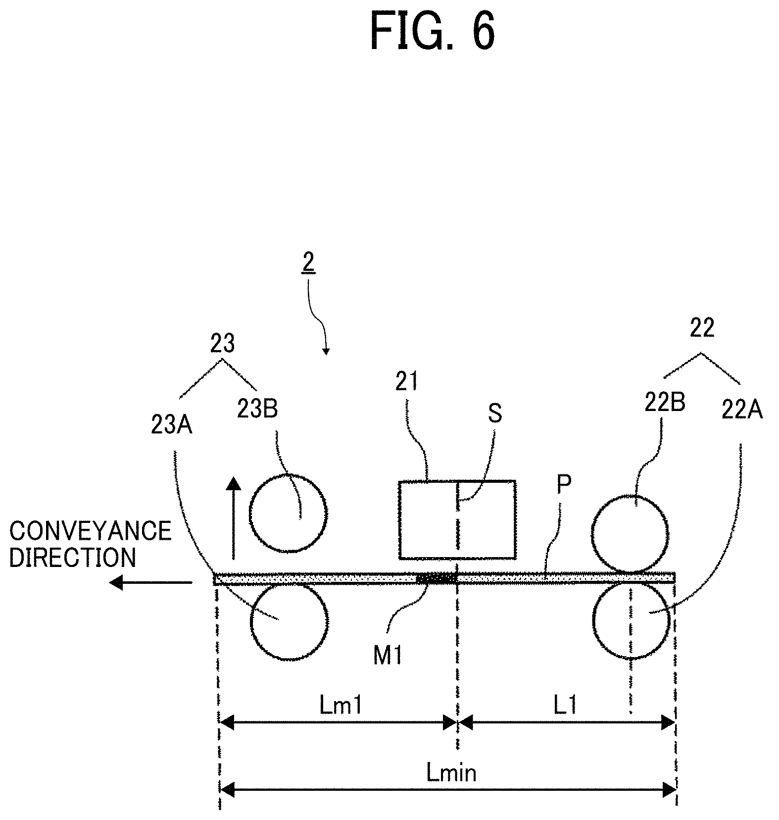
[0062] FIG. 6 is a schematic diagram illustrating an image reading apparatus 2 according to a third embodiment.
[0063] In the present embodiment, the image reading apparatus 2 is configured to have a relation of Lmin>(Lm1+L1), where L1 is a distance between an upstream reading conveyance roller pair 22 and a reading position S at which reading is performed by a reader 21, Lm1 is a distance between a leading end of a sheet P and an upstream end of a detection mark M1 in a sheet conveyance direction, and Lmin is a minimum sheet length passable inside the image reading apparatus 2.
[0064] Accordingly, the upstream reading conveyance roller pair 22 and a downstream reading conveyance roller pair 23 are arranged such that a length of (Lm1+L1) is greater than the minimum sheet length Lmin passable inside the image reading apparatus 2.
[0065] In such a case, after the detection mark M1 is detected, the downstream reading conveyance roller pair 23 contacts the sheet P before a trailing end of the sheet P passes through the upstream reading conveyance roller pair 22. Such arrangement enables the sheet P having undergone the mark detection to be reliably conveyed toward a downstream side. Thus, a detection mark M1 on any sheet having a length Lmin or greater can be reliably detected.
[0066] FIG. 7 is a schematic diagram illustrating an image reading apparatus 2 according to a fourth embodiment.
[0067] In the present embodiment, an upstream reading conveyance roller pair 22 (22A, 22B) is disposed such that one reading conveyance roller (a driven roller) 22B can be contacted against and separated from the other reading conveyance roller (a drive roller) 22A. The image reading apparatus 2 includes an upstream reading conveyance separator 29 that causes the driven roller 22B of the upstream reading conveyance roller pair 22 to be contacted against and separated from the drive roller 22A.
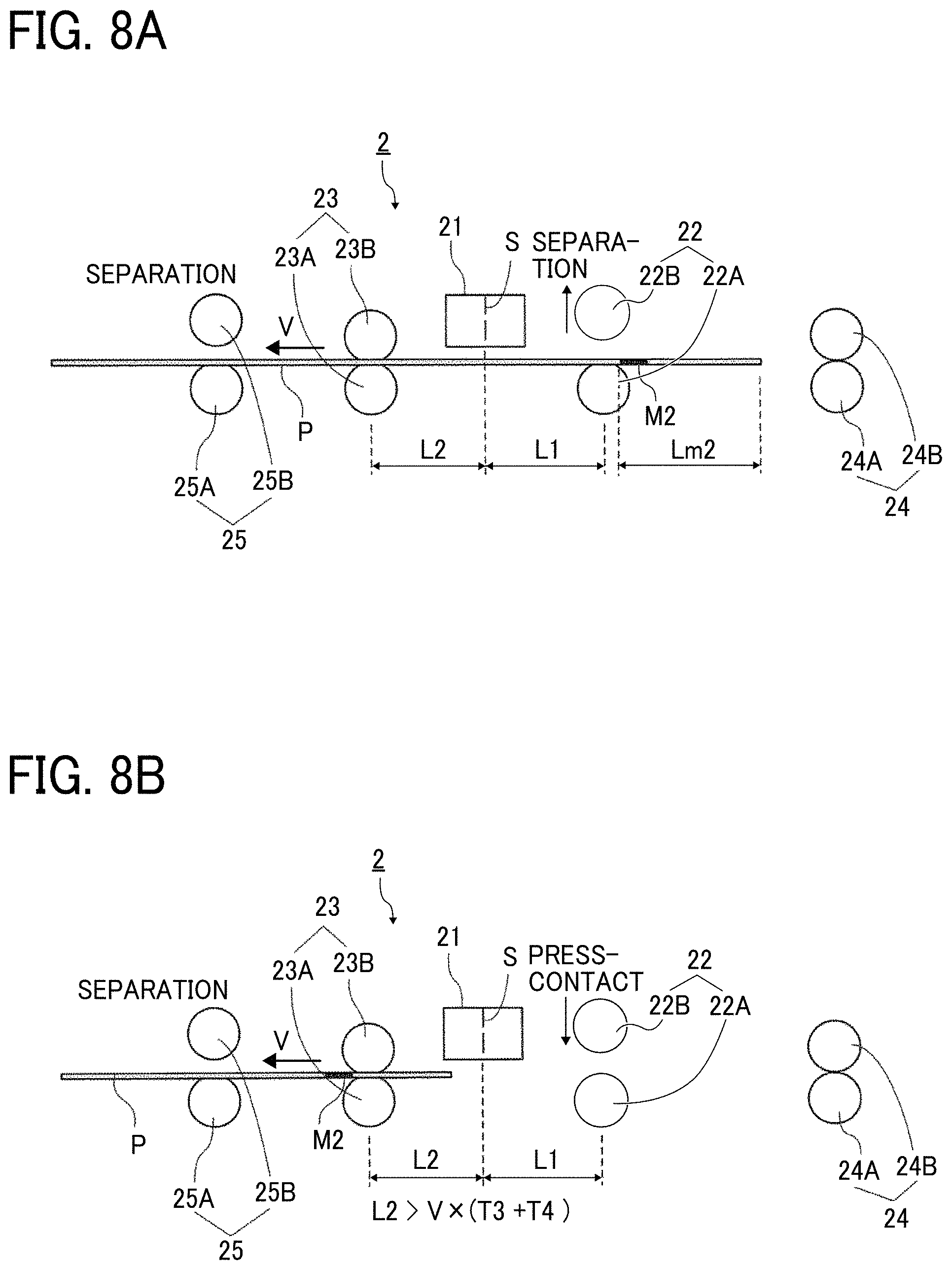
[0068] A reading operation according to the present embodiment is described with reference to FIGS. 8A and 8B.
[0069] In the present embodiment, as illustrated in FIG. 8A, the image reading apparatus 2 can handle a case where a distance Lm2 from a trailing end of a sheet P to a downstream end of a detection mark M2 in a sheet conveyance direction is greater than a distance L1 between a reader 21 and the upstream reading conveyance roller pair 22 (i.e., Lm2>L1).
[0070] That is, if Lm2>L1, the detection mark M2 passes a reading position S at which reading is performed by the reader 21 before a trailing end of the sheet P passes through the upstream reading conveyance roller pair 22. Consequently, the sheet P cannot be conveyed by only a downstream reading conveyance roller pair 23.
[0071] In such a case, as illustrated in FIGS. 8A and 8B, the driven roller 22B of the upstream reading conveyance roller pair 22 is separated before the detection mark M2 pass the reading position S at which reading is performed by the reader 21.
[0072] Accordingly, when the detection mark M2 passes the reading position 5, the sheet P can be conveyed by only the downstream reading conveyance roller pair 23, and reading is performed by the reader 21 with high accuracy.
[0073] FIG. 9 is a schematic diagram illustrating an image reading apparatus 2. according to a fifth embodiment.
[0074] In the present embodiment, the image reading apparatus 2 is configured to have a relation of Lmin>(Lm2+L2), where L2 is a distance between a reading position S at which reading is performed by a reader 21 and a downstream reading conveyance roller pair 23, Lm2 is a distance from a trailing end of a sheet P to a downstream end of a detection mark M2 in a sheet conveyance direction, and Lmin is a minimum sheet length passable inside the image reading apparatus 2.
[0075] Accordingly, an upstream reading conveyance roller pair 22 and the downstream reading conveyance roller pair 23 are arranged such that a length of (Lm2 +L2) is greater than the minimum sheet length Lmin passable inside the image reading apparatus 2.
[0076] In such a case, even if the upstream reading conveyance roller pair 22 is separated before detection of the detection mark M2, the detection mark M2 can be detected while the downstream reading conveyance roller pair 23 is conveying the sheet P toward a downstream side. Accordingly, a detection mark M2 on any sheet P having a length Lmin or greater can be reliably detected.
[0077] The present embodiment has been described using a conveyance rotator pair or a reading conveyance rotator pair as a roller pair. Alternatively, one or both of the rotators may be an endless belt. Moreover, in the present embodiment, one conveyance rotator or one reading conveyance rotator is disposed to be contactably separatable from the other conveyance rotator or the other reading conveyance rotator. However, both of the conveyance rotators or the reading conveyance rotators may be moved to contact and separate from each other
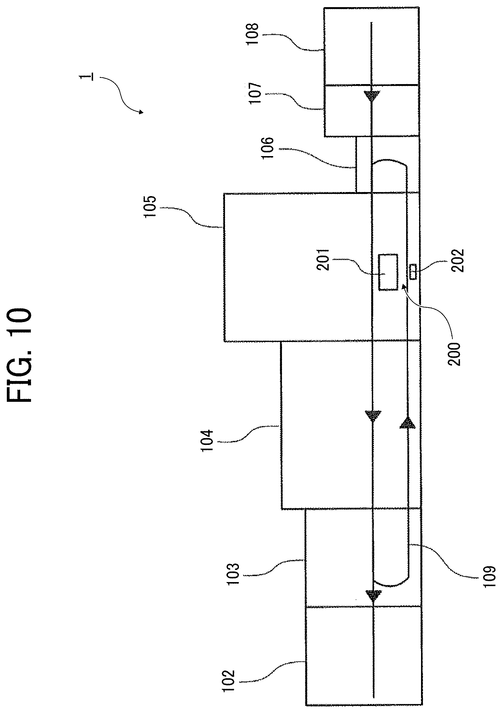
[0078] An example of an image forming system 1 according to the present embodiment is described is described with reference to FIG. 10.
[0079] The image forming system 1 includes a sheet ejection device 102, a cooling device 103, a drying device 104, an image forming device 105 as an image forming apparatus, a registration device 106, a pre-coating device 107, a sheet feeding device 108, and a detection device 200.
[0080] The sheet feeding device 108 stores a sheet P as a processing target (an object to be conveyed), and supplies the sheet P to a device such as the image forming device 105 at a later stage. An example of the sheet P includes transfer paper. However, the sheet P is not limited to the transfer paper. For example, the sheet P can be coated paper, thick paper, an overhead projector (OHP) sheet, a plastic film, and a copper foil as long as an image can be printed. In the present embodiment, the sheet P on which an image is to be formed has been described as a processing target (an object to be conveyed). However, the processing target is not limited to the sheet P. For example, a processing target (an object to be conveyed) may be a sheet such as a pre-preg on which an image is not to be formed.
[0081] In the pre-coating device 107, a sheet P as a processing target (an object to be conveyed) supplied from the sheet feeding device 108 is coated with pre-coating liquid. Accordingly, ink to be ejected by the image forming device 105 can be adapted to even different sheets P. The image forming system 1 may be configured without the pre-coating device 107.
[0082] The registration device 106 adjusts a conveyance time and a position of a sheet P with respect to the image forming device 105.
[0083] The image forming device 105 is an inkjet printing device. The image forming device 105 ejects ink to the sheet P to form an image on the sheet P. The image forming device 105 can form an output image based on a print instruction from a user, and detection marks M1 and M2 as detection target images on the sheet P. The image forming device 105 can be an electrophotographic printing device, instead of the inkjet printing device.
[0084] The drying device 104 dries the ink attached to the sheet P by the image forming device 105 to adapt the ink to the sheet P.
[0085] The cooling device 103 cools the sheet P heated by the drying device 104.
[0086] If single-sided printing is performed, the cooling device 103 feeds the sheet P on which an image is formed to the sheet ejection device 102 at a later stage. On the other hand, if duplex printing is performed, the cooling device 103 feeds the sheet P on which an image is formed to a reverser path 109.
[0087] In the reverser path 109, the fed sheet P is switched back to reverse a front surface and a back surface of the sheet P, and the reversed sheet P is conveyed. The sheet P conveyed along the reverser path 109 is conveyed to the image forming device 105 again, so that the image forming device 105 forms an image on a surface of the sheet P different from the surface on which the image is last formed. Subsequently, the sheet P is dried and cooled by the drying device 104 and the cooling device 103, and the resultant sheet P is fed as printed matter to the sheet ejection device 102 at a later stage.
[0088] The sheet ejection device 102 receives ejection of the sheet P on which the image is formed via the image forming device 105, the drying device 104, and the cooling device 103.
[0089] Moreover, the image forming device 105 includes a detection device 200 including the image reading apparatus of the present disclosure. The detection device 200 detects an end portion of a sheet P to be conveyed and a position of an image recorded on the sheet P so that a relative position between a plurality of reading devices and a relative position for each pixel of a single reading device are corrected. The detection device 200 can be disposed outside the image forming device 105.
[0090] The detection device 200 includes a reading device 201 as a reader and a position reference member 202.
[0091] The reading device 201 can be provided by, for example, a contact image sensor (CIS) in which a plurality of image capturing elements (e.g., complementary metal-oxide-semiconductor (CMOS) image sensors) is aligned. The reading device 201 receives reflected light from a reading target to output an image signal. Particularly, the reading device 201 treats a conveyance position of a sheet P on which an image is formed by the image forming device 105 and an image forming position with respect to the sheet P as reading targets. Moreover, the reading device 201 treats the position reference member 202 as a reading target.
[0092] The CIS to be applied to the reading device 201 generally has a configuration in which a plurality of sensor chips each having a plurality of pixels is arranged in a main scanning direction to obtain a necessary valid reading length in the main scanning direction.
[0093] In a case where the position reference member 202 expands and contracts due to the effects of heat generated by a peripheral member, the position reference member 202 does not function as an absolute position reference. Such a case may degrade the position detection accuracy. Accordingly, the position reference member 202 is made of a material not only having a lower linear expansion coefficient than a substrate of the reading device 201 but also having a negligibly small amount of contraction due to the effects of ambient temperature in position detection.
[0094] In the present embodiment, the position reference member 202 is formed of glass in consideration of a possible temperature variation range and a possible linear expansion coefficient. A material of the position reference member 202 is not limited to the glass. If a temperature variation range of the reading device 201 is wide, a material such as quartz glass is more suitable for the position reference member 202 so that a position of a medium is detected with high accuracy.
[0095] FIG. 11 is a diagram illustrating arrangement of the reading device 201 and the position reference member 202 in the detection device 200.
[0096] The position reference member 202 includes position reference members 202a and 202b. The position reference member 202 (202a, 202b) is disposed to a rotation member (a revolver) 203 that is rotated by a motor 204. The position reference member 202 (202a, 202b) is moved by the rotation member 203 rotated at a constant speed by the motor 204. With the rotation of the rotation member 203, the reference members 202a and 202b are switched so as to be arranged on a surface opposite the reading device 201 at a predetermined time.
[0097] Moreover, a reading background 205 is disposed to the rotation member 203. The reading background 205 is used for detection of an end portion of a sheet P to be conveyed and a position of an image recorded on the sheet P. With the rotation of the rotation member 203 by the motor 204, the position reference member 202 and the reading background 205 are selectively switched so as to be positioned opposite the reading device 201.
[0098] Moreover, the position reference member 202 (202a, 202b) is rotated to move in the sub-scanning direction at a constant speed so that a scale as a reference pattern including a line that is arranged on the position reference member 202 (202a, 202b) and extends in a predetermined direction is read for detection of an attachment inclination of the reading device 201 toward a sub-scanning direction.
[0099] In FIG. 11, the position reference member 202 (202a, 202b) is attached to the rotation member 203, and the position reference member 202. (202a, 202b) is moved in a sub-scanning direction at a constant speed. However, the arrangement of the position reference member 202 (202a, 202b) is not limited to the arrangement illustrated in FIG. 11. For example, the position reference member 202 (202a, 202b) may be arranged so as to be linearly movable.
[0100] One example of a pattern as a detection mark of a detection target image to be formed on a sheet P for image position adjustment is described with reference to FIG. 12.
[0101] The image forming system 1 has an adjustment mode for adjustment of an image position. If the adjustment mode is automatically or manually selected, as illustrated in FIG. 12, the image forming system 1 forms L-shape patterns a, b, c, and d as detection marks of detection target images near respective four corners on a sheet P by using an inkjet head (a detection mark addition unit) of the image forming device 105. The center positions of the patterns a, b, c, and d are respectively a0, b0, c0, and d0. The patterns a and b are formed on a leading end side of the sheet P in a sheet conveyance direction, and correspond to a detection mark M1. The patterns c and d are formed on a trailing end side of the sheet P in the sheet conveyance direction, and correspond to a detection mark M2.
[0102] The sheet P with the patterns a, b, c, and d is conveyed to the detection device 200 within the reverser path 109 through an ink drying process performed by the drying device 104 and a sheet cooling process performed by the cooling device 103.
[0103] The detection device 200 includes a CIS of a color image sensor disposed in an extending manner in a width direction as the reading device 201. The detection device 200 includes a plurality of roller pairs such as an upstream reading conveyance roller pair 22, a downstream reading conveyance roller pair 23, an upstream conveyance roller pair 24, and a downstream conveyance roller pair 25 for conveying a sheet P. As described above, the upstream reading conveyance roller pair 22, the downstream reading conveyance roller pair 23, the upstream conveyance roller pair 24, and the downstream conveyance roller pair 25 are arranged on an upstream side and a downstream side of the reading device 201 as a reader. Moreover, as described in the aforementioned first through third embodiments, the detection device 200 includes an upstream separator 26, a downstream separator 27, a downstream reading conveyance separator 28, and an upstream reading conveyance separator 29 as necessary.
[0104] The detection device 200 uses the reading device 201 to optically read an edge of the sheet P and the patterns a, b, c, and d on the sheet P conveyed by the plurality of conveyance rollers in a state in which the reading background 205 is arranged opposite the reading device 201.
[0105] Then, a central processing unit (CPU) (a mark coordinate calculator) disposed inside the image forming system 1 calculates coordinates of a center position of a pattern (a detection mark center position) on the sheet based on the reading result. For example, x-y coordinates of the center position of the pattern "a" is calculated at coordinates (H0, V0).
[0106] A pattern such as a cross, a rectangle, or a straight line may be used instead of the pattern illustrated in FIG. 12. The present embodiment has been described using a head that discharges an output image as the detection mark addition unit. However, a head dedicated for detection mark addition may be disposed in addition to a head for discharging an output image.
[0107] FIG. 13 is a diagram schematically illustrating types of image correction.
[0108] The CPU (e.g., a correction amount calculator) of the image forming system 1 calculates a displacement amount (a correction amount) that is displaced from a target position for the calculated center position of the pattern, and corrects a discharge time or a discharge position of ink from a print head such that a pattern is formed in the target position.
[0109] The image forming system 1 according to the present embodiment performs registration correction (i.e., correction by which an image position is moved parallel in a sheet width direction or a sheet conveyance direction), magnification correction, skew correction, trapezoid correction, or other correction as illustrated in FIG. 13. However, the correction to be performed by the image forming system 1 is not limited to the correction illustrated in FIG. 13.
[0110] In the image forming system 1, a sheet P may expand/contract or deform due to a process such as a printing process and a drying process subsequent to the printing process. In such a case, positions of images formed on a front surface and a back surface of the sheet P may be shifted from each other.
[0111] Accordingly, the image positions on the front surface and the back surface of the sheet P are preferably adjusted by such a correction method.
[0112] If the image positions on the front and back surfaces of the sheet P are to be adjusted, the CPU of the image forming system 1 performs pattern printing on a front surface, drying, cooling, reading of the pattern on the front surface, pattern printing on a back surface, drying, cooling, and reading of the pattern on the back surface in this order. Then, the CPU of the image forming system 1, based on the results of the pattern reading on the front and back surfaces, corrects a discharge time or a discharge position of ink from a print head such that positions of the images on the front and back surfaces match each other. Such correction can prevent image positions on the front surface and the back surface from being shifted from each other.
[0113] FIG. 14 is a diagram illustrating one example of the upstream separator 26 for the upstream conveyance rotator pair (an upstream conveyance roller pair) 24.
[0114] The upstream separator 26 includes an arm 41 and a motor 43. The arm 41 rotatably supports a rotation shaft of the driven roller 24B of the upstream conveyance roller pair 24. The motor 43 is connected to a rotation fulcrum 42 of the arm 41 to rotate the arm 41 about the rotation fulcrum 42.
[0115] The motor 43 rotates the arm 41 clockwise, so that driven roller 24B is separated from the drive roller (the conveyance roller) 24A. Moreover, the motor 43 rotates the arm 41 counterclockwise, so that the driven roller 24B contacts the drive roller 24A.
[0116] Herein, the upstream separator 26 has been described. However, each of the downstream separator 27, the downstream reading conveyance separator 28, and the upstream reading conveyance separator 29 can be similarly configured. The description has been given using an example in which a motor is used as a drive source of a separator. However, a separator using a cam, a solenoid, or a link may be applied.
[0117] Therefore, the use of the image reading apparatus of each of the embodiments can print an image with high accuracy.
[0118] The present disclosure has been described above with reference to specific embodiments but is not limited thereto. Various modifications and enhancements are possible without departing from scope of the disclosure. It is therefore to be understood that the present disclosure may be practiced otherwise than as specifically described herein. For example, elements and/or features of different illustrative embodiments may he combined with each other and/or substituted for each other within the scope of the present disclosure.
* * * * *
D00000
D00001
D00002
D00003
D00004
D00005
D00006
D00007
D00008
D00009
D00010
D00011
D00012

D00013

D00014

XML
uspto.report is an independent third-party trademark research tool that is not affiliated, endorsed, or sponsored by the United States Patent and Trademark Office (USPTO) or any other governmental organization. The information provided by uspto.report is based on publicly available data at the time of writing and is intended for informational purposes only.
While we strive to provide accurate and up-to-date information, we do not guarantee the accuracy, completeness, reliability, or suitability of the information displayed on this site. The use of this site is at your own risk. Any reliance you place on such information is therefore strictly at your own risk.
All official trademark data, including owner information, should be verified by visiting the official USPTO website at www.uspto.gov. This site is not intended to replace professional legal advice and should not be used as a substitute for consulting with a legal professional who is knowledgeable about trademark law.