Centering and Landing Platform for Hovering Flying Vehicles
Krauss; Ran ; et al.
U.S. patent application number 16/073399 was filed with the patent office on 2020-05-28 for centering and landing platform for hovering flying vehicles. The applicant listed for this patent is AIROBOTICS LTD.. Invention is credited to Meir Kliner, Ran Krauss.
| Application Number | 20200165008 16/073399 |
| Document ID | / |
| Family ID | 55022815 |
| Filed Date | 2020-05-28 |


View All Diagrams
| United States Patent Application | 20200165008 |
| Kind Code | A1 |
| Krauss; Ran ; et al. | May 28, 2020 |
Centering and Landing Platform for Hovering Flying Vehicles
Abstract
A landing platform for a hovering vehicle comprises an erectable and retractable boundary element which, when in erected position, defines a substantially closed volume.
| Inventors: | Krauss; Ran; (Tel Aviv, IL) ; Kliner; Meir; (Ramat Gan, IL) | ||||||||||
| Applicant: |
|
||||||||||
|---|---|---|---|---|---|---|---|---|---|---|---|
| Family ID: | 55022815 | ||||||||||
| Appl. No.: | 16/073399 | ||||||||||
| Filed: | May 19, 2016 | ||||||||||
| PCT Filed: | May 19, 2016 | ||||||||||
| PCT NO: | PCT/IL2016/050534 | ||||||||||
| 371 Date: | July 27, 2018 |
| Current U.S. Class: | 1/1 |
| Current CPC Class: | B64C 39/024 20130101; B64F 1/18 20130101; B64C 2201/027 20130101; G05D 1/0676 20130101; B64F 1/00 20130101; B64F 1/02 20130101; B64F 1/12 20130101; B64F 1/125 20130101; B64C 2201/201 20130101; B64C 2201/182 20130101 |
| International Class: | B64F 1/12 20060101 B64F001/12; B64F 1/00 20060101 B64F001/00 |
Foreign Application Data
| Date | Code | Application Number |
|---|---|---|
| Jan 28, 2016 | IL | PCTIL2016/050094 |
Claims
1. A landing platform for a hovering vehicle, comprising an erectable and retractable boundary element which, when in erected position, defines a substantially closed volume.
2. A landing platform according to claim 1, comprising a trapping element suitable to securely hold a weight attached to a cable.
3. The platform according to claim 2, wherein said trapping element is located at the center of said substantially closed volume.
4. The platform according to claim 2, wherein the trapping element comprises an electromagnetic element and the weight is made of a material that is attracted by magnetic forces.
5. The platform of claim 2, wherein the borders of said boundary element are quasi-continuum.
6. The platform of claim 1, wherein the boundary element comprises mechanical elements.
7. The platform of claim 1, wherein the boundary element comprises magnetic elements.
8. The platform of claim 1, wherein the boundary element comprises pneumatic elements.
9. A method for assisting in the landing of a hovering vehicle, comprising causing a weight to be lowered from said vehicle and erecting a boundary element such that said weight favors remaining within its boundaries, and encouraging the movement of said weight toward a trapping element located inside the boundaries of said boundary element, said trapping element being suitable to securely fasten said weight thereto.
10. The method of claim 9, wherein the trapping element is located at the center of said substantially closed volume.
11. The method of claim 9, wherein the borders of the boundary element are quasi-continuum.
12. The method of claim 9, wherein the trapping element comprises an electromagnetic element and the weight is made of a material that is attracted by magnetic forces.
13. The method of claim 9, wherein the boundary element comprises mechanical elements.
14. The method of claim 9, wherein the boundary element comprises magnetic elements.
15. The method of claim 9, wherein the boundary element comprises pneumatic elements.
Description
TECHNICAL FIELD
[0001] The present invention relates to hovering flying vehicles. More particularly, the invention relates to a landing platform suitable to guide such flying vehicles to land at a desired location thereon.
BACKGROUND
[0002] Hovering flying objects, such as drones, are becoming increasingly common in use nowadays and, in many applications, they fly autonomously. Accordingly, one of the problems encountered nowadays relates to issues associated with the autonomous landing, when it is desired that such landing take place at a precise location on a landing platform. Many different solutions have been offered, including various ways to "grab" the drone during the landing procedure, or the provision of cumbersome appendices to be attached to the drone, all of which render the process complex and expensive and which lack precision.
[0003] The term "drone", as used herein, is meant to refer to all flying objects that may be brought to an essentially vertical landing autonomously on a landing platform, regardless of whether at some other time during their flight they are guided or supervised by a human or other system. This term will be used throughout this description, for the sake of brevity.
[0004] It is an object of the present invention to provide a method and system suitable to overcome the drawbacks of the prior art, and to facilitate the landing of a drone on a landing platform.
SUMMARY
[0005] In one aspect the invention relates to a landing platform for a hovering vehicle, comprising an erectable and retractable boundary element which, when in erected position, defines a substantially closed volume.
[0006] In another aspect the invention relates to a landing platform comprising a trapping element suitable to securely hold a weight attached to a cable. The trapping element can be located at the center of said substantially closed volume or elsewhere. In a further embodiment of the invention the trapping element comprises an electromagnetic element and the weight is made of a material that is attracted by magnetic forces. In this context, the term "substantially closed volume" is meant to indicate a volume the boundaries of which are clearly defined by delimiting elements, even though gaps may exist that allow passage into and out of said volume.
[0007] In one embodiment of the invention the borders of the boundary element are quasi-continuum, by which is meant that gaps may exist in its circumference. In another embodiment of the invention the boundary element comprises mechanical elements. In still another embodiment of the invention the boundary element comprises magnetic elements and in yet embodiment of the invention the boundary element comprises pneumatic elements.
[0008] The invention also encompasses a method for assisting in the landing of a hovering vehicle, comprising causing a weight to be lowered from said vehicle and erecting a boundary element such that said weight favors remaining within its boundaries, and encouraging the movement of said weight toward a trapping element located inside the boundaries of said boundary element, said trapping element being suitable to securely fasten said weight thereto.
BRIEF DESCRIPTION OF THE DRAWINGS
[0009] FIG. 1A is a schematic representation of a drone suitable for use with the system of the invention;
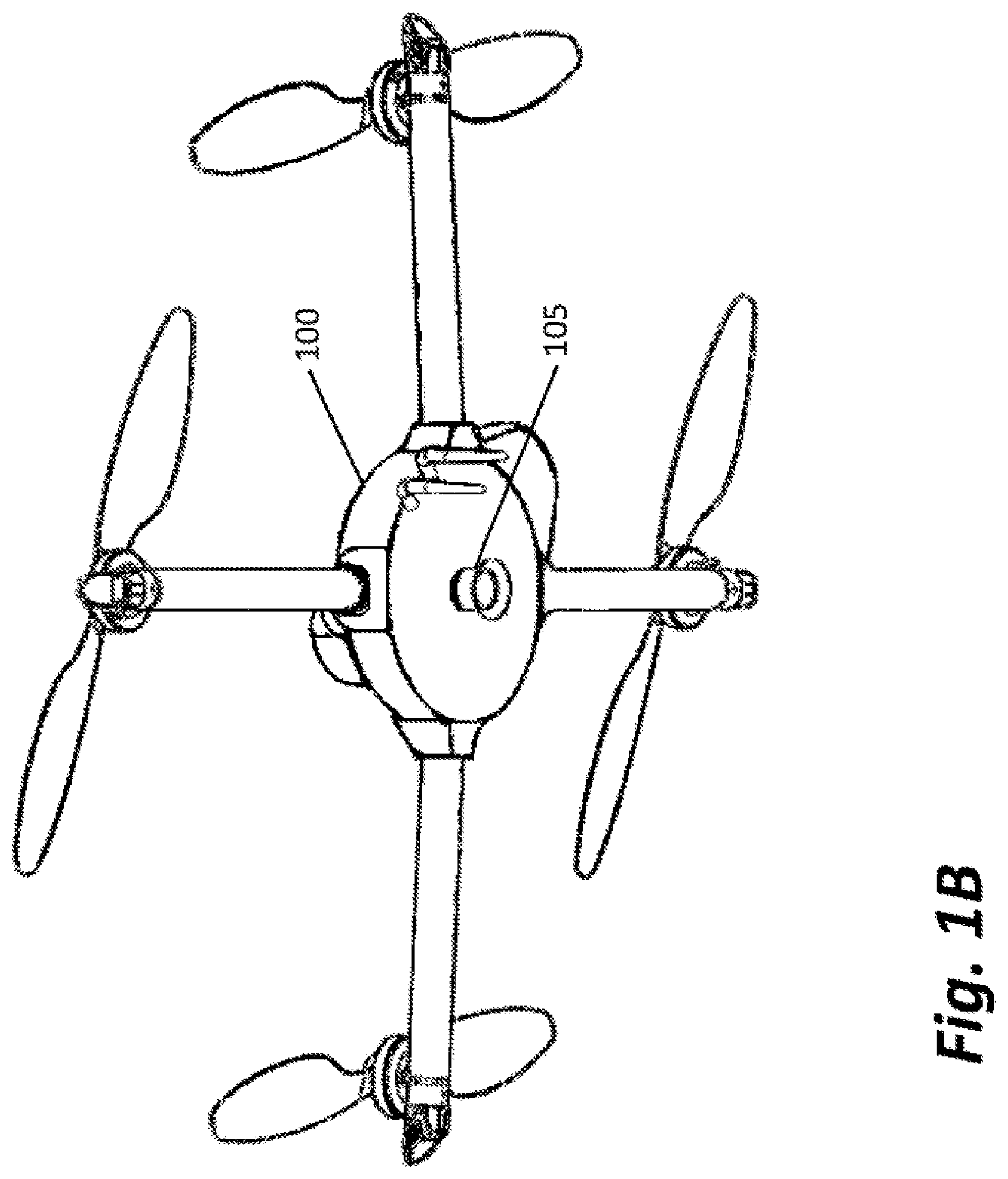
[0010] FIG. 1B is a bottom view of the drone of FIG. 1A;
[0011] FIG. 2 is a schematic description of the first stage of a landing procedure according to one embodiment of the invention;
[0012] FIG. 3 shows a landing platform according to a particular embodiment of the invention at the beginning of the preparations for landing;
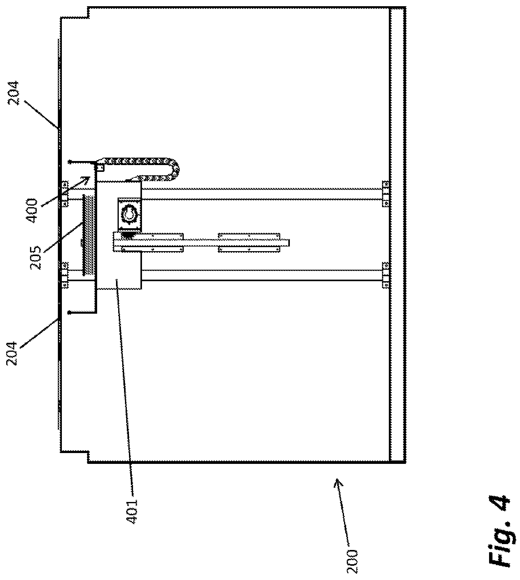
[0013] FIG. 4 is a cross-section of the landing platform taken along the AA axis of FIG. 2;
[0014] FIG. 5A shows an intermediate position of centering aids according to a particular embodiment of the invention in perspective view;
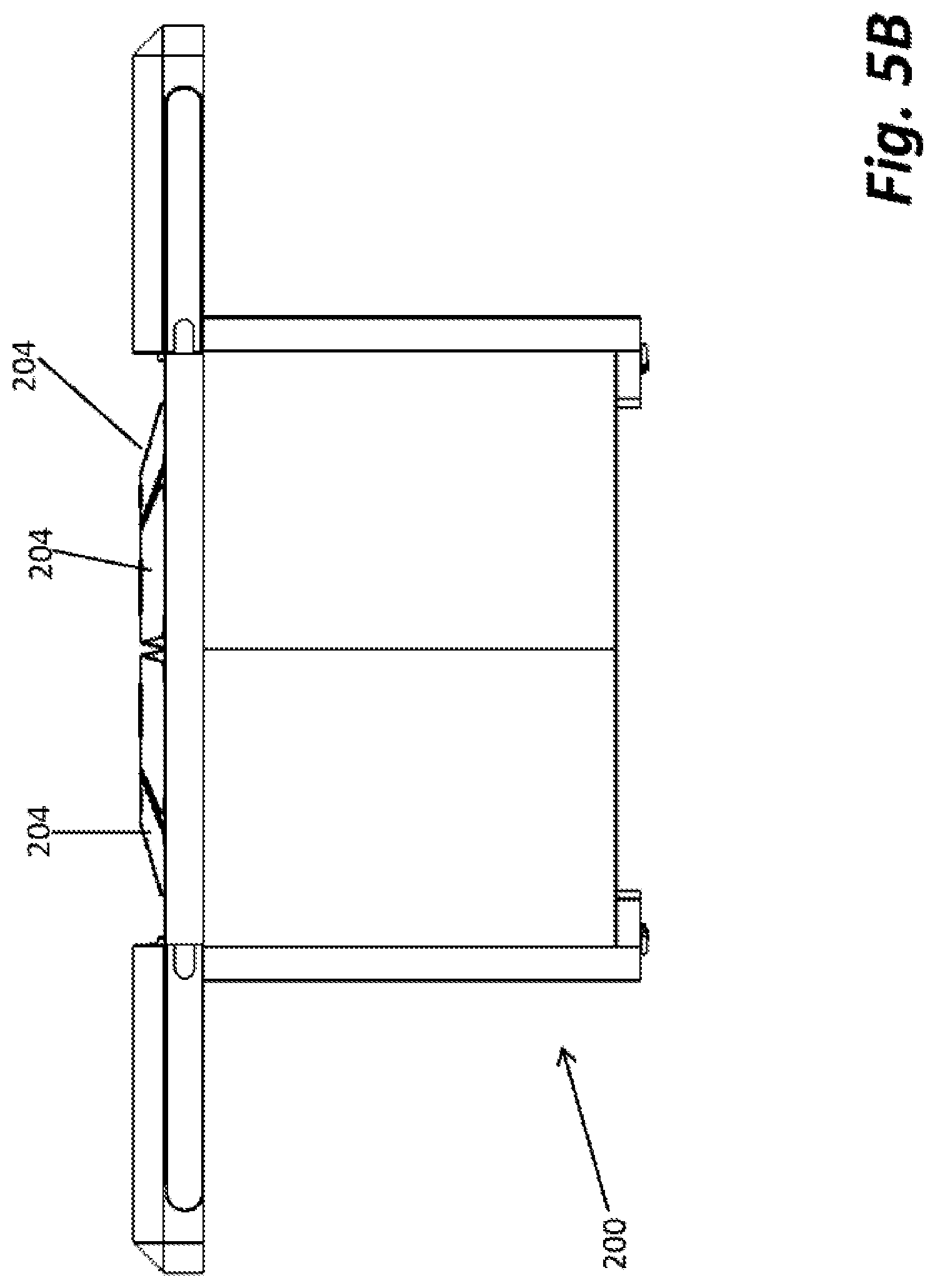
[0015] FIG. 5B shows the intermediate position of centering aids of FIG. 5A in side view;
[0016] FIG. 6A shows the final position of centering aids, in perspective view;
[0017] FIG. 6B shows the final position of the centering aids of FIG. 6A, in side view;
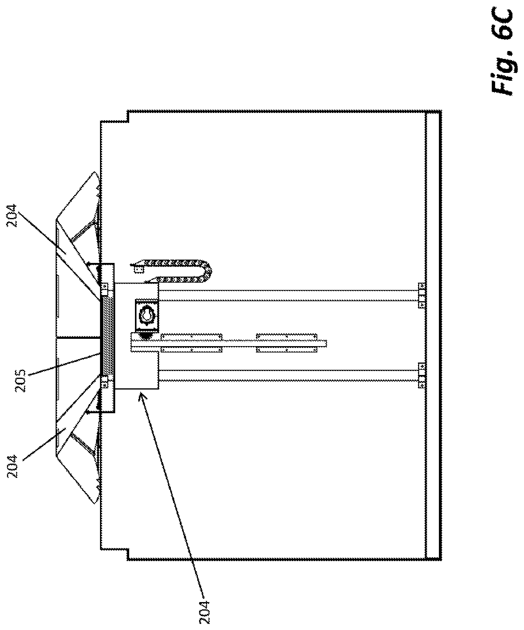
[0018] FIG. 6C is the same cross-section as in FIG. 4, taken in the final position of the centering aids; and
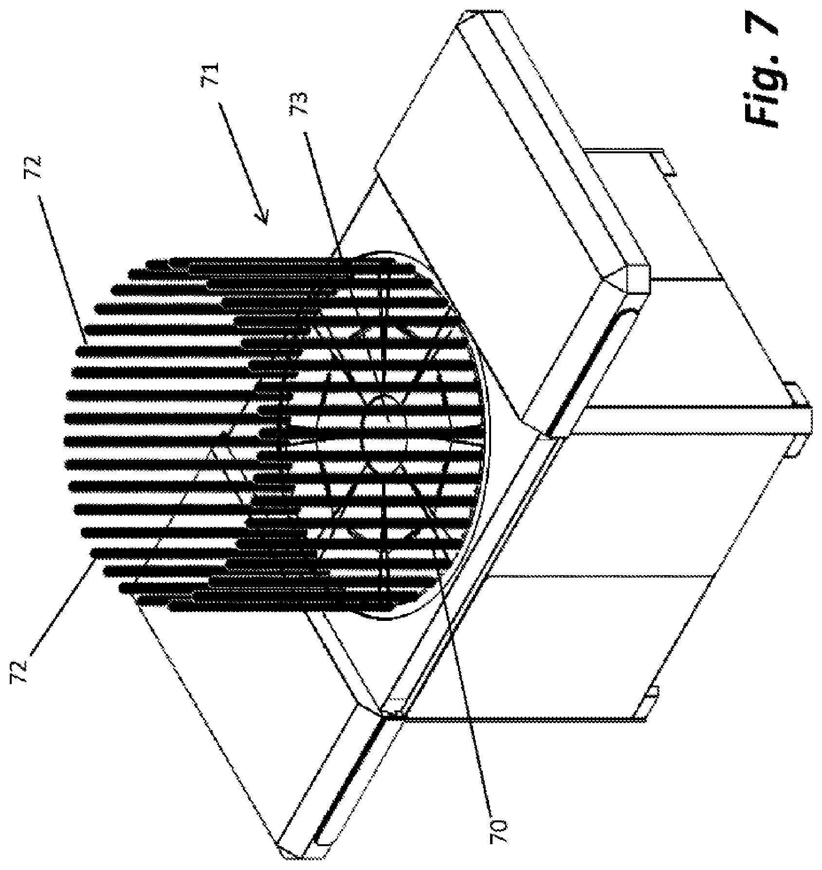
[0019] FIG. 7 schematically illustrates the general structure of the capturing system of the invention, including a boundary element and a trapping element.
DETAILED DESCRIPTION
[0020] The invention will be better understood through the description of one particular embodiment of the invention, it being understood that this specific embodiment is not meant to limit the invention in any way and is only provided for the purpose of illustration.
[0021] A drone suitable for use with the system according to the invention is schematically illustrated in FIG. 1A, in perspective view, where 100 indicates the main body of the drone, to which four arms 101-104, each provided with a propeller, are attached. FIG. 1B shows the drone of FIG. 1A, viewed from the bottom and reveals a winch assembly 105, which will be further described hereinafter.
[0022] Winch assembly 105 is designed to release a cable from the drone, which is provided with a weight, as schematically shown in FIG. 2, in which the cable is indicated by numeral 206 and the weight by 207. FIG. 2 shows an early stage of the approach for landing of drone 100 toward a platform 200, provided with a base, 201, covering elements 202a and 202b, landing platform 203, provided with centering aids 204 and centering magnetic assembly, 205, all of which will be explained in greater detail hereinafter.
[0023] Turning now to FIG. 3, platform 200 is shown at the beginning of the preparations for landing. Covering elements 202a and 202b, which in a non-operating condition (not shown) covered landing platform 203, are now moved aside to expose it by a linear displacing mechanism (not shown). Centering aids 204, consisting in the figure of 8 trapezoidal segments, are in non-operative position, i.e., are essentially flat at platform 203 level or below it. FIG. 4, which is a cross-section of the platform 200, taken along the AA axis of FIG. 2, shows an actuation mechanism 400 that is designed to move centering aids 204 so as to change their angle relative to the surface of landing platform 203. In FIG. 4 mechanism 400 is in a resting position, i.e., centering aids 204 are flat, as shown in FIG. 3. As actuating assembly 401 moves upwards, centering aids are raised.
[0024] FIGS. 5A and 5B show an intermediate position of centering aids 204, in perspective and in side view, respectively. FIGS. 6A and 6B show the final position of centering aids 204, in perspective and in side view, respectively. FIG. 6C is the same cross-section as in FIG. 4, taken in the final position of centering aids 204.
[0025] Centering magnetic assembly 205 (FIG. 2), also referred to herein as "trapping element", comprises elements suitable to create a strong electromagnetic field that converges toward its center. Weight 207, which is attached to cable 206, is made of ferromagnetic material that is attracted by the magnetic forces generated by centering magnetic assembly 205. However, because of environmental or technical reasons, weight 207 may not always reach close enough to the center of the landing platform, to be captured by the magnetic forces. Therefore, centering aids 204 are used to define an enclosed volume, with the magnetic assembly 205 at its center, such that no matter where weight 207 touches, when lowered by the drone's winch, it will always be directed toward the center, where the magnetic forces will tether it to the landing platform. Additional fastening means (not shown) can be provided, to maintain the weight at the center of the landing platform, once captured. Once the drone is securely tethered to the landing platform, the winch is activated and the cable is wound, while pulling the drone down toward landing. Centering aids 204 are flattened again, to provide a flat landing space, although in some embodiments they may be partially or fully left in an erected state, if the size of the drone permits. Landing platform 203 may then be lowered together with the drone, if desired, and if it is required to store the drone, covering elements 202a and 202b can be slid close. When the boundary element is mechanical in nature, it is possible to flatten it either autonomously, by synchronizing its motion with the approach of the drone, or the weight of the drone can be used to flatten it. Different mechanisms can be devised for this purpose, which will be apparent to the skilled person, for instance using springs, counterweights, or hydraulic arrangements.
[0026] Having now illustrated the invention through a detailed, specific embodiment thereof, it will be easier to understand its broader reach and scope. FIG. 7 illustrates a landing platform and uses the same box structure described earlier, for the sake of simplicity, it being understood that the shape and structure of the parts that are not involved in the landing step are not essential to the invention, can be of any other type, and do not limit the invention in any way. For instance, the invention could be implemented on a ship or on the top of a building, where no box or cover exist.
[0027] Broadly speaking, the landing platform of the invention comprises a landing surface, generally indicated at 70, which is the surface on which the drone will rest after landing. The landing surface can be of any type as long as it is suitable for the drone to rest on and, e.g., can be rough or smooth, plane or sloped, fixed or movable. It can further be provided with accessories, e.g., for locking the drone in place once landed, as one might wish to do, for instance if the landing platform is located on a ship and particularly in rough weather.
[0028] A boundary element 71 is any means suitable to define a volume of space within which the drone will find itself while approaching surface 70 for landing. A simple example of a boundary element 71 is the cone defined by centering aids 204 described with reference to FIGS. 2 through 6. However, it is important to understand that boundary element 71 can be of very many kinds, as will be explain in greater detail below, as long as it fulfills the following conditions:
[0029] 1--it defines a substantially closed space that defines a volume suitable to house the drone after landing; and
[0030] 2--its boundaries are not fixed and can be partially or fully erected and retracted at will.
[0031] The shape of the boundary element is not critical and it can be of any shape that is suitable for the specific landing platform that employs it, for instance, it can be substantially round, square, polygonal, etc.
[0032] While often the positioning of the weight will be at the center of the landing platform that is not an essential element of the invention, inasmuch as landing platforms of different geometries can be devised for different needs, which may not have the optimal landing place at their center.
[0033] The term "erected", as used herein, should be understood to not be limited to physical erection, as in the example of FIGS. 2-6, but to apply to any creation of limiting boundaries, be they tangible or not.
[0034] In FIG. 7 the schematic representation of boundary element 71 consists of a plurality of individual elements 72, which together form a quasi-continuum (and in some cases, even a continuum). For example, elements 72 may represent a magnetic field with a component directed toward the center of plan 70, which may be useful for directing a ferromagnetic weight, such as weight 207 of FIG. 2, toward the center. However, electromagnetic forces are only one example of suitable centering aids. In another example weight 204 is not made of a ferromagnetic material and elements 72 are air streams caused by a plurality of strong blowers (or by a blower with split channels) that create each a stream of air with a radial component, such that the weight 207 is directed toward the center of the platform. Utilizing blowers has the advantage of being not only easy to start and end, but also the air stream can be adjusted in strength easily at will. As will be apparent to the skilled person from the above examples, many different boundary elements can be provided, with physical, magnetic, aerodynamic, etc. presence, and the invention is not limited to any particular technique for providing it. Similarly, the weight 207 can be of many different kinds and should be adapted to the specific boundary technique employed. However, for the sake of simplicity this element will be referred to as "weight" throughout, even though in some cases an actual weight may not be required to correctly position the cable that will tether the drone to the landing platform.
[0035] Once the weight is inside the boundary element 71 and has reached its center area, it is captured by trap 73 using a securing mechanism, which can be of any type suitable to maintain the weight in its position and which, of course, has to be adapted to the type and shape of weight employed. The securing mechanism can be mechanic, electromagnetic, hydraulic or pneumatic, or any combination of the above. The actual nature of the securing mechanism is not important, as long as it fulfills the above requirements.
[0036] Trap 73 may be located at the landing platform level or above or below it and may be movable. So, for instance, once the weight has been captured, the trap may be lowered below the landing platform level.
[0037] The above description of preferred embodiments has been provided for the purpose of illustration and is not meant to limit the invention in any way, except as defined in the appended claims.
* * * * *
D00000
D00001
D00002
D00003
D00004
D00005
D00006
D00007
D00008
D00009
D00010
D00011
XML
uspto.report is an independent third-party trademark research tool that is not affiliated, endorsed, or sponsored by the United States Patent and Trademark Office (USPTO) or any other governmental organization. The information provided by uspto.report is based on publicly available data at the time of writing and is intended for informational purposes only.
While we strive to provide accurate and up-to-date information, we do not guarantee the accuracy, completeness, reliability, or suitability of the information displayed on this site. The use of this site is at your own risk. Any reliance you place on such information is therefore strictly at your own risk.
All official trademark data, including owner information, should be verified by visiting the official USPTO website at www.uspto.gov. This site is not intended to replace professional legal advice and should not be used as a substitute for consulting with a legal professional who is knowledgeable about trademark law.