Parachute
Morikawa; Hiroshi
U.S. patent application number 16/612971 was filed with the patent office on 2020-05-28 for parachute. The applicant listed for this patent is Hiroshi Morikawa. Invention is credited to Hiroshi Morikawa.
| Application Number | 20200164991 16/612971 |
| Document ID | / |
| Family ID | 64274421 |
| Filed Date | 2020-05-28 |


| United States Patent Application | 20200164991 |
| Kind Code | A1 |
| Morikawa; Hiroshi | May 28, 2020 |
Parachute
Abstract
A conventional parachute requires a velocity pressure during descent in order to open the parachute. As a result, a minimum descent distance and time are required from the beginning to the end of the parachute opening operation and use at low altitude has to be restricted. In order to remedy this issue, an airtight tube and a compressed gas device are provided together in a section of the parachute having the largest annular shape when the parachute has been opened. The tube is annularly expanded by the pressure of the gas, and the parachute is forcibly deployed and opened.
| Inventors: | Morikawa; Hiroshi; (Yachimata-shi, JP) | ||||||||||
| Applicant: |
|
||||||||||
|---|---|---|---|---|---|---|---|---|---|---|---|
| Family ID: | 64274421 | ||||||||||
| Appl. No.: | 16/612971 | ||||||||||
| Filed: | May 7, 2018 | ||||||||||
| PCT Filed: | May 7, 2018 | ||||||||||
| PCT NO: | PCT/JP2018/018440 | ||||||||||
| 371 Date: | November 12, 2019 |
| Current U.S. Class: | 1/1 |
| Current CPC Class: | B64D 19/00 20130101; B64D 17/72 20130101 |
| International Class: | B64D 17/72 20060101 B64D017/72 |
Foreign Application Data
| Date | Code | Application Number |
|---|---|---|
| May 13, 2017 | JP | 2017-107155 |
Claims
1. A parachute comprising: a membrane that has a truncated conical shape when opened, an airtight tube in a rim section of largest annular shape of the membrane, a compressed gas generation device for inflating the tube, a connector in a section of smallest annular shape of the membrane, and a belt, rope, or hook for holding a person, an animal, or an object, in midair.
2. The parachute of claim 1, further comprising an airtight tube and a compressed gas generation device for inflating that tube provided together in the section of smallest annular shape of the membrane.
Description
TECHNICAL FIELD
[0001] The present invention is a parachute configured so that when a person jumps from an aircraft in flight, an object is lowered or dropped from the aircraft, or the aircraft itself has lost its balance to be in a falling state, the parachute is opened (hereafter, called "parachute opening") and stable descent is achieved regardless of descent velocity and altitude position.
BACKGROUND ART
[0002] Regarding parachute opening of a parachute typified by a currently used hemispherical type parachute, in midair, first, a small pilot parachute is opened, and wind pressure of descent is used to discharge and pull out the parachute from a storage bag and once render the parachute in a rod shape, whereby wind is applied to a lower section of the parachute, and a force thereof utilized to open the parachute. Moreover, when directly jumping from the aircraft, the parachute and the aircraft are provisionally joined to pull out the parachute from the storage bag and render it in a rod shape for a while, whereby wind pressure is caused to act on the lower section of the parachute to open the parachute. Furthermore, from its shape and method of use, a maximum load occurs all at once during parachute opening.
Problem to be Solved by the Invention
[0003] As mentioned above, parachute opening of the parachute has required a velocity pressure needed for the parachute to open, and a descent distance to generate the velocity pressure. Moreover, changing of the descent velocity or reduction of the load during parachute opening, and so on, have been impossible. Furthermore, there has been no measure for reducing an impact force occurring during landing, and the only measure when making a splash landing on water has been to rely on buoyancy of a descent object.
Means for Solving the Problem
[0004] When parachute opening has been performed, the parachute according to the present invention has a truncated conical shape, in other words, a shape like a shuttlecock in battledore, or a shuttlecock in badminton, and a main body is made of a thin membrane (1), and seeks stable descent. The parachute does not open by a force occurring due to air resistance, and when the parachute is opened, an annular airtight tube (2) provided on a rim section representing a largest annular shape, and a compressed gas generation device (3) for inflating that tube are employed, and the parachute designed and created according to the present invention is deployed and opened when required, regardless of descent velocity and height at a time of operation.
[0005] Moreover, a small annular airtight tube (6) and a compressed gas generation device (7) are provided separately from those of the rim section in a tip section of the cone, and are provided for attenuation of impact during landing or to achieve buoyancy when a splash landing is made on water, as required.
Effect of the Invention
[0006] In midair, a conventional parachute has required time from beginning to completion of a parachute opening operation, and has required velocity pressure due to descent velocity. Therefore, it has not been able to be used at low altitude. In the parachute according to the present invention, these conditions are rendered unnecessary, and the parachute is forcibly opened using a compressed gas, so a descent object can be landed safely and with little damage. Moreover, both impact in a lateral direction and impact in a longitudinal direction can be absorbed and handled by the tubes (2), (6). A shape of the annular section can be changed by changing a pressure of the tube (2), so a projective area in a vertical direction of the parachute can be changed, whereby the descent velocity can be changed. Furthermore, if the tube (2) is partitioned into small compartments in a circumferential direction and pressure of each of the compartments is changed, then descent direction can also be controlled. The parachute can be used also as a life preserver by utilizing buoyancy of the tubes, during a splash landing.
BRIEF DESCRIPTION OF THE DRAWINGS
[0007] FIG. 1 is a cross-sectional perspective view of a parachute according to the present invention at a time of parachute opening.
[0008] FIG. 2 is a cord, belt, hook, or the like, for coupling to a descent object attached to a parachute truncated section.
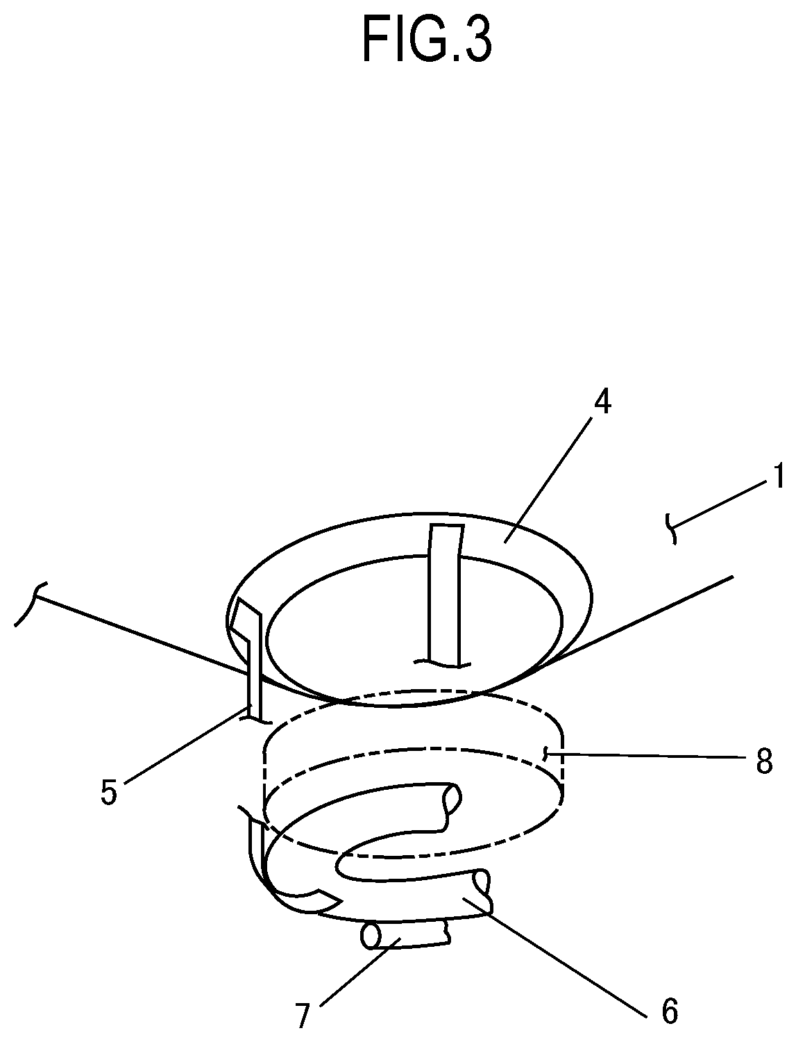
[0009] FIG. 3 is a perspective view explaining a combination of each of structures in the parachute truncated section.
EMBODIMENTS FOR CARRYING OUT THE INVENTION
[0010] Next, embodiments of the present invention will be mentioned. It is a parachute made by a thin membrane (1) that, when opened, has a truncated conical shape like in FIG. 1, in other words, a shape like a shuttlecock in battledore or a shuttlecock in badminton. An airtight tube (2) and a compressed gas generation device (3) are provided in a largest annular section. When visibility is required, a transparent membrane may be used, or a window provided. (a) When utilized by a person, the parachute is inserted in a folding storage box taking care to prevent it becoming tangled when opening. The belt, or the like, of FIG. 3 and a currently generally used parachute wearing belt are coupled. In order to start operation, the compressed gas generation device (3) is activated, by pulling on a cord, by generating an electric wave, or automatically, and so on. The tube (2) is inflated by a supplied gas, and the storage bag is opened, or broken whereby the parachute is discharged and opened.
(b) When adopted in a drone type aircraft typifying a small aircraft, a frame having prepared therein a fitting for coupling to the parachute which is annular in order to protect a plurality of rotor blades, is attached beforehand to a drone side. (Although it seems that drones are still not of a fixed type and that various types of drones are conceivable, it seems that there are also some drones that have an outer frame designed from the start) The parachute is folded annularly, inserted in the storage bag created annularly in the same manner, and coupled to a periphery of the descent object. (c) When the descent object is freight, a coupling apparatus is attached to the freight, and fastened by a belt, or the like. Operation in (b), (c) is the same as in (a).
[0011] An annular tube having the same function as the airtight tube (2) concentrically provided with a plurality of compressed gas generators, can be provided to this parachute between the rim section and a center.
[0012] If a gas pressure in the tube (2) is changed, a projective area of the parachute with respect to descent changes, and descent velocity can be changed. If, at a time of parachute opening, a load in a radial direction applied to the membrane becomes excessive, then it results in the tube (2) wrinkling in a circumferential direction or twisting to reduce the load. Although when a conical opening angle is large and has become an obtuse angle, undesirable movement such as sideslip and gyration conceivably occurs during use, this is dealt with at that time by providing a bottom surface of the parachute with the likes of a rib or a fin.
[0013] The compressed gas generation device (3) may also be disposed separated from the tube (2) by being additionally provided with a conduit.
[0014] FIG. 3 is a schematic view showing a relationship of a lower section of the parachute, an outer frame (8) of a flying object, and an airtight annular tube (6). When actually used, everything is rigidly bound using a belt, a cord, or the like. The annular tube (6) is for absorbing and reducing an impact occurring during landing, and is provided together with a compressed gas generation device in the same manner as p (2). There may be a plurality of stages of the annular tubes (6).
[0015] When this parachute is utilized in an aircraft, in the case of a helicopter, a configuration is adopted whereby the storage bag or a storage device is attached on an axis of a main rotor blade. In the case of an aircraft, the storage bag or storage device is provided above a main wing in the case of a high-wing type aircraft, and along a fuselage in the case of a low-wing type aircraft, and a storage device designed so as to easily discharge or be easily broken by the compressed gas, is provided.
[0016] Even in a conventionally used hemispherical parachute, utilization of the tube (2) and the compressed gas generation device (3) is effective, and is thought to reduce or prevent torch accidents. However, there is a risk of the parachute being damaged when descent velocity is fast.
INDUSTRIAL APPLICABILITY
[0017] The reality is that, in the case of a conventional aircraft, there is still no proactive safety device, and if the rotor blade is damaged in the case of a helicopter or if damage occurs to an engine or other main section in the case of an aircraft, then fatal damage immediately occurs. Although it is difficult for such damage to be cut to zero, the present invention is thought to significantly reduce such damage.
[0018] Moreover, the present invention is thought to contribute greatly to development of newly emerging drone type aircraft.
DESCRIPTION OF REFERENCE NUMERALS
[0019] 1 membrane of parachute main body [0020] 2 airtight tube [0021] 3 compressed gas generation device for tube (2) [0022] 4 reinforcement band of parachute truncated section [0023] 5 belt, cord for coupling [0024] 6 tube (6) for attenuation of impact occurring during landing [0025] 7 compressed gas generation device for tube (6) [0026] 8 outer frame of flying object
* * * * *
D00000
D00001
D00002
XML
uspto.report is an independent third-party trademark research tool that is not affiliated, endorsed, or sponsored by the United States Patent and Trademark Office (USPTO) or any other governmental organization. The information provided by uspto.report is based on publicly available data at the time of writing and is intended for informational purposes only.
While we strive to provide accurate and up-to-date information, we do not guarantee the accuracy, completeness, reliability, or suitability of the information displayed on this site. The use of this site is at your own risk. Any reliance you place on such information is therefore strictly at your own risk.
All official trademark data, including owner information, should be verified by visiting the official USPTO website at www.uspto.gov. This site is not intended to replace professional legal advice and should not be used as a substitute for consulting with a legal professional who is knowledgeable about trademark law.