Quick Clamping Device for a Portable Power Tool, in Particular an Angle Grinder, Having in Particular at least One Output Shaft
Sinzig; Bruno ; et al.
U.S. patent application number 16/631825 was filed with the patent office on 2020-05-28 for quick clamping device for a portable power tool, in particular an angle grinder, having in particular at least one output shaft . The applicant listed for this patent is Robert Bosch GmbH. Invention is credited to Bruno Luescher, Marcus Schuller, Bruno Sinzig, Andreas Zurbruegg.
| Application Number | 20200164485 16/631825 |
| Document ID | / |
| Family ID | 63079924 |
| Filed Date | 2020-05-28 |


| United States Patent Application | 20200164485 |
| Kind Code | A1 |
| Sinzig; Bruno ; et al. | May 28, 2020 |
Quick Clamping Device for a Portable Power Tool, in Particular an Angle Grinder, Having in Particular at least One Output Shaft that is Drivable in Rotation
Abstract
A quick clamping device for a portable power tool, in particular an angle grinder, includes an output shaft that is configured to be driven in rotation and at least one clamping unit that is configured to fix an application tool unit to the output shaft without tools. The clamping unit has at least one movably mounted clamping element configured to apply a clamping force to the application tool unit in a clamping position of the clamping element. The clamping element is formed by a positive-locking element that is movable transversely to an axis of rotation of the output shaft and is configured to engage behind at least a subregion of the application tool unit in a positive-locking manner so as to secure the application tool unit.
| Inventors: | Sinzig; Bruno; (Oberbipp, CH) ; Zurbruegg; Andreas; (Luterbach, CH) ; Schuller; Marcus; (Dettenhausen, DE) ; Luescher; Bruno; (Zofingen, CH) | ||||||||||
| Applicant: |
|
||||||||||
|---|---|---|---|---|---|---|---|---|---|---|---|
| Family ID: | 63079924 | ||||||||||
| Appl. No.: | 16/631825 | ||||||||||
| Filed: | July 31, 2018 | ||||||||||
| PCT Filed: | July 31, 2018 | ||||||||||
| PCT NO: | PCT/EP2018/070750 | ||||||||||
| 371 Date: | January 16, 2020 |
| Current U.S. Class: | 1/1 |
| Current CPC Class: | B24B 45/006 20130101; B24B 23/022 20130101 |
| International Class: | B24B 45/00 20060101 B24B045/00; B24B 23/02 20060101 B24B023/02 |
Foreign Application Data
| Date | Code | Application Number |
|---|---|---|
| Aug 11, 2017 | DE | 10 2017 214 118.2 |
Claims
1. A quick-change clamping device for a portable power tool, comprising: at least one output shaft configured be driven in rotation; and at least one clamping unit configured to fix an insert-tool unit to the output shaft without use of tools, the clamping unit having at least one movably mounted clamping element configured to apply a clamping force to the insert-tool unit when the clamping element is in a clamping position, wherein the clamping element is formed by a positive-engagement element that is movable transversely in relation to a rotation axis of the output shaft and that is configured to engage with positive engagement behind at least a sub-region of the insert-tool unit so as to secure the insert-tool unit.
2. The quick-change clamping device as claimed in claim 1, further comprising at least one operating unit configured to move the clamping element into one or more of the clamping position and into a release position of the clamping element in which the insert-tool unit can is configured to be removed from the clamping unit, wherein the clamping element is formed by a toggle lever mounted so as to be rotatable about a rotation axis that is perpendicular to the rotation axis of the output shaft, wherein the clamping element has at least one first eccentric force introduction point, upon which a spring force acts, in at least one operating state, so as to rotate the clamping element into a clamping position, and wherein the operating unit is configured to act upon a second eccentric force introduction point that is spaced apart from the first eccentric force introduction point so as to rotate the clamping element into a release position.
3. The quick-change clamping device as claimed in claim 2, wherein the operating unit has at least one spring element configured to directly apply a force to the clamping element, in at least one operating state, at least substantially perpendicularly in relation to the rotation axis of the output shaft.
4. The quick-change clamping device as claimed in claim 1, wherein the clamping unit has at least one spring element configured to move the clamping element into a clamping position, and at least one deflection element configured to deflect a force of the spring element into a direction that is at least substantially perpendicular to the rotation axis of the output shaft.
5. The quick-change clamping device as claimed in claim 1, wherein the clamping unit has at least one first spring element configured to move the clamping element into a clamping position, and at least one second spring element that is weaker than the first spring element and that is configured to move the clamping element into a release position.
6. The quick-change clamping device as claimed in claim 1, wherein the clamping element has at least one resilient sub-section that is configured to be deflected at least substantially perpendicularly in relation to the rotation axis of the output shaft so as to receive the insert-tool unit with positive engagement.
7. The quick-change clamping device as claimed in claim 1, wherein the clamping unit has at least one ramp, which is configured to deflect at least a sub-region of the clamping element differently, in dependence on an axial position, perpendicularly in relation to the rotation axis of the output shaft.
8. The quick-change clamping device as claimed in claim 1, wherein the clamping element is formed by a toggle lever mounted so as to be rotatable about a rotation axis of the clamping element that is perpendicular to the rotation axis of the output shaft, and wherein one end of the clamping element is guided in a coulisse that is mounted so as to be movable relative to the rotation axis of the clamping element.
9. A power tool, comprising: an output shaft configured to be driven in rotation; a quick-change clamping device including at least one clamping unit configured to fix an insert-tool unit to the output shaft without use of tools, the clamping unit having at least one movably mounted clamping element configured to apply a clamping force to the insert-tool unit when the clamping element is in a clamping position, wherein the clamping element is formed by a positive-engagement element that is movable transversely in relation to a rotation axis of the output shaft and that is configured to engage with positive engagement behind at least a sub-region of the insert-tool unit so as to secure the insert-tool unit.
10. A power tool system comprising: an insert-tool unit; and at least one power tool including: an output shaft configured to be driven in rotation, and a quick-change clamping device that includes at least one clamping unit configured to fix the insert-tool unit to the output shaft without use of tools, the clamping unit having at least one movably mounted clamping element configured to apply a clamping force to the insert-tool unit when the clamping element is in a clamping position, wherein the clamping element is formed by a positive-engagement element that is movable transversely in relation to a rotation axis of the output shaft and that is configured to engage with positive engagement behind at least a sub-region of the insert-tool unit so as to secure the insert-tool unit.
11. (canceled)
12. The quick-change clamping device as claimed in claim 1, wherein the portable power tool is configured as a power angle grinder.
13. The power tool as claimed in claim 9, wherein the power tool is configured as a power angle grinder.
Description
PRIOR ART
[0001] Already known from DE 100 17 458 A1 is a quick-change clamping device for a portable power tool, in particular a power angle grinder, having at least one output shaft that can be driven in rotation, having at least one clamping unit that, for the purpose of fixing an insert-tool unit to the output shaft without use of tools, has at least one movably mounted clamping element for applying a clamping force to the insert-tool unit when the clamping element is in a clamping position, and having at least one operating unit for moving the clamping element into the clamping position and/or into a release position of the clamping element, in which the insert-tool unit can be removed from the clamping unit and/or from the output shaft.
DISCLOSURE OF THE INVENTION
[0002] The invention is based on a quick-change clamping device for a portable power tool, in particular for a power angle grinder, having at least one output shaft that can be driven in rotation, having at least one clamping unit that, for the purpose of fixing an insert-tool unit to the output shaft without use of tools, has at least one movably mounted clamping element for applying a clamping force to the insert-tool unit when the clamping element is in a clamping position.
[0003] It is proposed that the clamping element be formed by a positive-engagement element that is movable transversely in relation to a rotation axis of the output shaft and that is designed to engage with positive engagement behind at least a sub-region of the insert-tool unit for the purpose of securing the insert-tool unit. Preferably, for the purpose of securing the insert-tool unit, the clamping unit is designed to engage with positive engagement behind the insert-tool unit by a movement, directed at least partially radially in relation to a rotation axis of the output shaft, of at least a sub-section of the clamping element. Preferably, the quick-change clamping device additionally has at least one driving means that, for the purpose of transmitting a driving force to the insert-tool unit, has at least one torque transmission region spaced apart axially from a rotation axis of the output shaft. Preferably, for the purpose of directly applying clamping force to the insert-tool unit, the movably mounted clamping element is arranged in a clamping position of the clamping element. Particularly preferably, the clamping force is applied, in particular automatically, by the quick-change clamping device, such as, for example, by a spring element. Particularly preferably, the clamping element is in an operating state, without operator intervention in a clamping position. The clamping element can be brought into a release position, in particular by an operator intervention. Preferably, the clamping element is arranged, at least partly, in the output shaft. The output shaft is formed, in particular, by a hollow spindle. Preferably, the output shaft surrounds the clamping element at least partially, in particular completely, along a circumferential direction around a rotation axis of the output shaft. Preferably, the clamping element is connected to the output shaft in a rotationally fixed manner. Preferably, the clamping element is mounted so as to be swivelable about a swivel axis of the clamping element. Preferably, the swivel axis of the clamping element runs transversely, in particular at least substantially perpendicularly, in relation to the rotation axis of the output shaft. Preferably, the swivel axis of the clamping element runs at least substantially perpendicularly in relation to a clamping axis of the clamping unit. A "clamping axis" is to be understood here to mean, in particular, an axis of the clamping unit along which an axial securing force of the clamping unit can be exerted upon the insert-tool unit for the purpose of fixing the insert-tool unit to the output shaft, and/or along which a transmission element of the clamping unit is movably mounted for the purpose of moving the clamping element. "At least substantially perpendicularly" is intended here to define, in particular, an alignment of a direction relative to a reference direction, wherein the direction and the relative direction, in particular as viewed in one plane, enclose an angle of 90.degree. and the angle has a maximum deviation of, in particular, less than 8.degree., advantageously less than 5.degree., and particularly advantageously less than 2.degree.. Preferably, the clamping element is realized as a clamping jaw. Preferably, the clamping element is designed to secure the insert-tool unit axially to the output shaft. Preferably, the clamping element, at least in the clamping position, preferably engages, at least partially, in the insert-tool unit, in particular in a fixing recess of the insert-tool unit. Preferably, at least when the insert-tool unit has been fixed by means of the clamping unit, the clamping element engages behind a clamping extension of the insert-tool unit.
[0004] "Designed" is to be understood to mean, in particular, specially programmed, configured and/or equipped. That an element and/or a unit are/is designed for a particular function is to be understood to mean, in particular, that the element and/or the unit fulfill/fulfills and/or execute/executes this particular function in at least one application state and/or operating state. "Movably mounted" is to be understood to mean, in particular, a mounting of an element and/or of a unit, the element and/or the unit having a movement capability, in particular dissociated from an elastic deformation of the element and/or of the unit, along a movement axis, of more than 5 mm, preferably of more than 10 mm, and particularly preferably of more then 50 mm, and/or about a movement axis, along an angular range of more than 10, preferably of more than 5.degree., and particularly preferably of more than 15.degree.. A "positive-engagement element that is movable transversely in relation to a rotation axis of the output shaft" in this context is to be understood to mean, in particular, a clamping element designed to produce a positive-engagement connection in at least one operating state, in particular in a clamping position. Preferably, the positive-engagement element has, within its movement range, at least one movement component that extends radially in relation to the rotation axis of the output shaft. "Engage with positive engagement behind" in this context is to be understood to mean, in particular, that at least a sub-section of the clamping element engages behind at least a sub-region of the insert-tool unit, in the axial direction of the rotation axis of the output shaft. Preferably, in an engaged-behind state, as viewed from an axial direction of the rotation axis of the output shaft, along a flow of force, the sub-section of the clamping element is at least partially concealed by the sub-region of the insert tool.
[0005] Owing to the design of the quick-change clamping device according to the invention, securing of the insert-tool unit can be achieved, in particular, in an advantageously safe and simple manner. In particular, it is possible to achieve reliable securing of the insert-tool unit, by positive engagement, in transmission housing unit axial direction. An advantageously high degree of operating convenience can be achieved as a result. In particular, fixing of the insert-tool unit can be achieved in an advantageously convenient and safe manner, without use of tools.
[0006] It is additionally proposed that the quick-change clamping device have at least one operating unit for moving the clamping element into the clamping position, and/or into a release position of the clamping element in which the insert-tool unit can be removed from the clamping unit, and at least one force transformation unit, which is coupled to the operating unit and which is designed to amplify a force from the operating unit acting upon the clamping element. Preferably, by means of a mechanical connection, the clamping element can be moved between at least the operating element, the operating unit and the clamping element, by means of the operating unit, into the clamping position and/or into the release position. Preferably, the operating element is realized as an operating lever, in particular as a swivel-mounted operating lever, as an operating button and/or as an operating pull lever. Also conceivable in principle, however, are other designs of the operating element that are considered appropriate by persons skilled in the art. It is also conceivable, however, that an electrical signal can be generated by means of an operating element of the operating unit, by means of which electrical signal an actuator, which is designed to move the clamping element into the clamping position and/or into the release position, can be controlled. The operating unit may be realized as a mechanical, electrical and/or electronic operating unit, which is designed to move the clamping element into the clamping position and/or into the release position as a result of an operating command of an operator and/or of an operating force of an operator. The force transformation unit is intended, in particular, to amplify a force acting from the operating unit upon the clamping element, by means of a transformation and/or in particular by means of an additional force-boosting element such as, for example, a pressure cylinder. Preferably, a movement of the operating element of the operating unit undergoes transformation when being transmitted to the clamping element. Preferably, a long movement of the operating element is transformed into a short, and thus stronger, movement of the clamping element. The force transformation unit in this case may be realized in various ways, considered appropriated by persons skilled in the art. An advantageously high degree of operating convenience can be achieved as a result. In particular, actuation of the clamping unit can be achieved even with a small expenditure of force.
[0007] Furthermore, it is proposed that the clamping element be formed by a toggle lever mounted so as to be rotatable about a rotation axis that is perpendicular to the rotation axis of the output shaft. Preferably, the clamping element has a positionally fixed rotation axis, the clamping element being mounted so as to be rotatable about same, at least within a limited angular range. Preferably, the clamping element is mounted so as to be rotatable within a defined angular range that is delimited by two end stops. The clamping element is designed, in particular, to tilt for the purpose of changing between the clamping position and the release position. Preferably, at at least one end of the toggle lever, the clamping element has a positive-engagement extension that is designed to engage directly behind the insert-tool unit. It would also be conceivable in this case, in particular, for the output shaft, likewise, additionally to have a fixed positive-engagement extension, in which the insert-tool unit must be inserted. This makes it possible, in particular, to provide an advantageous design of the clamping element. In particular, it is possible to provide a clamping element by means of which, advantageously, a moment of force can be applied.
[0008] It is additionally proposed that the clamping element have at least one first eccentric force introduction point, upon which a spring force acts, in at least one operating state, for the purpose of rotating the clamping element into a clamping position. Preferably, the first eccentric force introduction point is eccentric with respect to the rotation axis of the clamping element. Preferably, the first eccentric force introduction point is both eccentric with respect to the rotation axis of the clamping element and eccentric with respect to the rotation axis of the output shaft. In particular, the first eccentric force introduction point is eccentric with respect to the rotation axis of the clamping element, as viewed in the axial direction of the output shaft. Particularly preferably, force is also introduced eccentrically into the force introduction point. In particular, force is introduced parallel to the rotation axis of the output shaft. This means, in particular, that a force vector of a force acting upon the force introduction point intersects neither the rotation axis of the clamping element nor the rotation axis of the output shaft. Preferably, the clamping element is rotated by the eccentricity, in particular up to a stop that realizes the clamping position, when force is introduced at the first eccentric force introduction point.
[0009] It is additionally proposed that the quick-change clamping device have at least one operating unit for moving the clamping element into the clamping position, and/or into a release position of the clamping element in which the insert-tool unit can be removed from the clamping unit, wherein the operating unit, for the purpose of rotating the clamping element into a release position, is designed to act upon a second eccentric force introduction point that is spaced apart from the first eccentric force introduction point. Preferably, the second eccentric force introduction point is arranged on a side of the rotation axis of the clamping element that is opposite to the first eccentric force introduction point. Preferably, the second eccentric force introduction point, for the purpose of rotating the clamping element, is arranged in a direction opposite to that of the first eccentric force introduction point. In particular, the second eccentric force introduction point is eccentric with respect to the rotation axis of the clamping element. Preferably, the second eccentric force introduction point is both eccentric with respect to the rotation axis of the clamping element and eccentric with respect to the rotation axis of the output shaft. In particular, the second eccentric force introduction point is eccentric with respect to the rotation axis of the clamping element, as viewed in the axial direction of the output shaft. Particularly preferably, force is also introduced eccentrically into the force introduction point. In particular, force is introduced parallel to the rotation axis of the output shaft. Preferably, when force is introduced at the second eccentric force introduction point, the clamping element is rotated by the eccentricity, in particular up to a stop that realizes the release position.
[0010] It is further proposed that the clamping unit have at least one spring element designed to directly apply a force to the at least one clamping element, in at least one operating state, at least substantially perpendicularly in relation to the rotation axis of the output shaft. Preferably, the at least one spring element is designed to exert a spring force perpendicularly in relation to the rotation axis of the output shaft. A "spring element" is to be understood to mean, in particular, a macroscopic element having at least one extent that, in a normal operating state, can be varied elastically by at least 10%, in particular by at least 20%, preferably by at least 30%, and particularly advantageously by at least 50% and that, in particular, generates a counter-force, which is dependent on a variation of the extent and preferably proportional to the variation and which counteracts the variation. An "extent" of an element is to be understood to mean, in particular, a maximum distance of two points of a perpendicular projection of the element on to a plane. A "macroscopic element" is to be understood to mean, in particular, an element having an extent of at least 1 mm, in particular of at least 5 mm, and preferably of at least 10 mm. In particular, this makes it possible, advantageously, to achieve direct tilting of the clamping element by the spring element. In particular, advantageously, a spring force can thus be of a small magnitude.
[0011] It is further proposed that the clamping unit have at least one spring element designed to move the at least one clamping element into a clamping position, and at least one deflection element, which is designed to deflect a force of the spring element into a direction that is at least substantially perpendicular to the rotation axis of the output shaft. Preferably, the at least one spring element is designed to exert a spring force parallel to the rotation axis of the output shaft, the deflection element being designed to deflect the force of the spring element by 90.degree.. A deflection by the deflection element may be realized, for example, by means of a wedge-shaped portion on the deflection element. Preferably, the deflection element is formed by a ring having a triangular cross section. Preferably, the spring element is designed to exert a spring force axially upon the deflection element, the deflection element, because of the resultant axial movement, displacing the clamping element radially and deflecting it at least substantially perpendicularly in relation to the rotation axis of the output shaft. An advantageous application of force upon the clamping element can thereby be achieved, in particular even in the case of radially restricted structural space. In particular, an advantageous deflection of force can be achieved. As a result, advantageously, engagement behind can be realized.
[0012] It is furthermore proposed that the clamping unit have at least one first spring element designed to move the at least one clamping element into a clamping position, and at least one second spring element, which is weaker than the first spring element and which is designed to move the at least one clamping element into a release position. Preferably, at least one effective spring force of the second spring element is substantially less than an effective spring force of the first spring element. Preferably, the second spring element is designed to move the clamping element into a release position in the absence of loading by the first spring element. This makes it possible, in particular, for the clamping element to move automatically into a release position as soon as an operator takes the loading by the first spring element, such as, for example, by pulling back the spring element. This makes it possible, in particular, to achieve an advantageous force efficiency, in particular, in the case of an axially aligned first spring element, a release of the quick-change clamping device, in particular since the clamping element must be deflected at least partially transversely in relation to the rotation axis for the purpose of release.
[0013] It is further proposed that the clamping element have at least one resilient sub-section that, in the case of the insert-tool unit being received with positive engagement, is designed to be deflected at least substantially perpendicularly in relation to the rotation axis of the output shaft. Preferably, the resilient sub-section is designed, in the case of the insert-tool unit being received with positive engagement, to be deflected, at least substantially perpendicularly in relation to the rotation axis of the output shaft, in a direction away from the rotation axis. Preferably, the resilient sub-section is designed, in the case of the insert-tool unit being released, to be deflected, at least substantially perpendicularly in relation to the rotation axis of the output shaft, in a direction toward the rotation axis. Preferably, the clamping element is realized, in particular, in the manner of a clamp having at least two elongated extensions. Preferably, the clamping element is realized at least partially in a U-shape, the two free ends each being connected to a base side via a resilient sub-section. This makes it possible, in particular, to provide advantageously safe securing of the insert-tool unit. In particular, at least a portion of a force required to secure the insert-tool unit can be applied by the clamping element itself. In this way, for example, a component quantity or a structural space can be kept advantageously small.
[0014] It is further proposed that the clamping unit have at least one ramp, which is designed to deflect at least a sub-region of the clamping element differently, in dependence on an axial position, perpendicularly in relation to the rotation axis of the output shaft. Preferably, the ramp is arranged, in particular, on a spindle cup of the output shaft and/or on the clamping element. The ramp is designed, in particular, to act directly between the clamping element and the output shaft. In particular, the ramp forms a contact surface between the clamping element and the output shaft. The ramp in this case is inclined, in particular, in relation to a rotation axis of the output shaft. Preferably, over a distance the ramp may change in inclination with respect to the rotation axis of the output shaft. This makes it possible, in particular, to achieve advantageously precise guiding of the clamping element. In particular, it is possible to achieve advantageously exact positioning of the clamping element in dependence on an axial position.
[0015] It is further proposed that the clamping element be formed by a toggle lever mounted so as to be rotatable about a rotation axis that is perpendicular to the rotation axis of the output shaft, wherein one end of the clamping element is guided in a coulisse that is mounted so as to be movable relative to the rotation axis of the clamping element. Preferably, the coulisse is guided so as to be movable axially relative to the rotation axis of the clamping element. Preferably, the coulisse is moved axially relative to the rotation axis of the clamping element, for the purpose of adjusting the quick-change clamping device, in particular from a clamping position into a release position and/or vice versa. Particularly preferably, in the case of the coulisse being moved axially relative to the rotation axis of the clamping element, the clamping element is swiveled about the rotation axis. Preferably, one end of the clamping element may be guided both directly and indirectly in the coulisse, such as, for example, via a lever guided on and/or in the coulisse, and/or via a roller guided on and/or in the coulisse.
[0016] Furthermore, the invention is based on a power tool, in particular a power angle grinder, having an output shaft that can be driven in rotation, and having a quick-change clamping device.
[0017] The invention is additionally based on a power tool system comprising the power tool, having the quick-change clamping device, and comprising an insert-tool unit that can be received in the quick-change clamping device.
[0018] The quick-change clamping device according to the invention, the power tool and the power tool system are not intended in this case to be limited to the application and embodiment described above. In particular, the quick-change clamping device according to the invention, the power tool and the power tool system may have individual elements, components and units that differ in number from a number stated herein, in order to fulfill a functionality described herein.
DRAWING
[0019] Further advantages are given by the following description of the drawing. The drawings show fifteen exemplary embodiments of the invention. The drawings, the description and the claims contain numerous features in combination. Persons skilled in the art will also expediently consider the features individually and combine them to create appropriate further combinations.
[0020] There are shown:
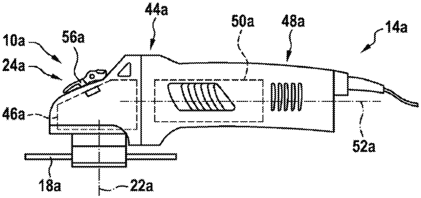
[0021] FIG. 1 a portable power tool according to the invention, having a quick-change clamping device according to the invention, in a schematic representation,
[0022] FIG. 2 a detail of the portable power tool according to the invention and of the quick-change clamping device according to the invention, in a schematic sectional representation, in a clamping position,
[0023] FIG. 3 a detail of an alternative portable power tool according to the invention and of an alternative quick-change clamping device according to the invention, in a schematic sectional representation, in a clamping position,
[0024] FIG. 4 a detail of a further alternative portable power tool according to the invention and of an alternative quick-change clamping device according to the invention, in a schematic sectional representation, in a clamping position,
[0025] FIG. 5 a detail of a further alternative portable power tool according to the invention and of an alternative quick-change clamping device according to the invention, in a schematic sectional representation, in a clamping position,
[0026] FIG. 6 a detail of a further alternative portable power tool according to the invention and of an alternative quick-change clamping device according to the invention, in a schematic sectional representation, in a clamping position,
[0027] FIG. 7 a detail of a further alternative portable power tool according to the invention and of an alternative quick-change clamping device according to the invention, in a schematic sectional representation, in a clamping position,
[0028] FIG. 8 a detail of a further alternative portable power tool according to the invention and of an alternative quick-change clamping device according to the invention, in a schematic sectional representation, in a clamping position,
[0029] FIG. 9 a detail of a further alternative portable power tool according to the invention and of an alternative quick-change clamping device according to the invention, in a schematic sectional representation, in a clamping position,
[0030] FIG. 10 a detail of a further alternative portable power tool according to the invention and of an alternative quick-change clamping device according to the invention, in a schematic sectional representation, in a clamping position,
[0031] FIG. 11 a detail of a further alternative portable power tool according to the invention and of an alternative quick-change clamping device according to the invention, in a schematic sectional representation, in a clamping position,
[0032] FIG. 12 a detail of a further alternative portable power tool according to the invention and of an alternative quick-change clamping device according to the invention, in a schematic sectional representation, in a clamping position,
[0033] FIG. 13 a detail of a further alternative portable power tool according to the invention and of an alternative quick-change clamping device according to the invention, in a schematic sectional representation,
[0034] FIG. 14 a detail of a further alternative portable power tool according to the invention and of an alternative quick-change clamping device according to the invention, in a schematic sectional representation, in a release position,
[0035] FIG. 15 a detail of a further alternative portable power tool according to the invention and of an alternative quick-change clamping device according to the invention, in a schematic sectional representation, in a clamping position, and
[0036] FIG. 16 a detail of a further alternative portable power tool according to the invention and of an alternative quick-change clamping device according to the invention, in a schematic sectional representation, in a clamping position.
DESCRIPTION OF THE EXEMPLARY EMBODIMENTS
[0037] FIG. 1 shows a portable power tool 14a, realized as a power angle grinder, having a quick-change clamping device 10a. It is also conceivable, however, for the portable power tool 14a to be of a different design, considered appropriate by persons skilled in the art, such as, for example, designed as a power circular saw, as a power sander, or the like. The portable power tool 14a comprises a transmission housing 44a for accommodating or mounting a transmission unit 46a of the portable power tool 14a. The transmission housing 44a is preferably made of a metallic material. It is also conceivable, however, for the transmission housing 44a to be made of a different material, considered appropriate by persons skilled in the art, such as, for example, of plastic, or the like. The transmission unit 46a is preferably realized as a bevel gear transmission. The transmission unit 46a comprises, in particular, an output shaft 12a, which can be driven in rotation and to which an insert-tool unit 18a can be fixed, in particular by means of the quick-change clamping device 10a. The power tool 14a comprises the output shaft 12a that can be driven in rotation. The output shaft 12a is preferably realized as a hollow spindle, in which the quick-change clamping device 10a is arranged, at least partially (see FIG. 2). A protective hood unit, not represented in greater detail here, can be arranged on the transmission housing 44a, in a manner already known to persons skilled in the art. An ancillary handle, not represented in greater detail here, can be arranged on the transmission housing 44a, in a manner already known to persons skilled in the art. The portable power tool 14a comprises a motor housing 48a, for accommodating and/or mounting a drive unit 50a of the portable power tool 14a. The drive unit 50a is preferably designed, in a manner already known to persons skilled in the art, to drive the output shaft 12a in rotation about a rotation axis 22a of the output shaft 12a, by means of a combined action with the transmission unit 46a. The rotation axis 22a of the output shaft 12a is at least substantially perpendicular to a drive axis 52a of the drive unit 50a. The drive unit 50a is preferably realized as an electric-motor unit. It is also conceivable, however, for the drive unit 50a to be of a different design, considered appropriate by persons skilled in the art, such as, for example, designed as an internal-combustion drive unit, as a hybrid drive unit, as a pneumatic drive unit, or the like. The power tool 14a, the quick-change clamping device 10a, and the insert-tool unit 18a that can be received in the quick-change clamping device 10a form a power tool system.
[0038] FIG. 2 shows a sectional view of the portable power tool 14a, in particular in the region of the transmission housing 44a, and of the quick-change clamping device 10a. The quick-change clamping device 10a for the portable power tool 14a, which comprises the output shaft 12a that can be driven in rotation, comprises at least one clamping unit 16a which, for the purpose of fixing the insert-tool unit 18a to the output shaft 12a without the use of tools, has at least one movably mounted clamping element 20a, 20a', for applying a clamping force to the insert-tool unit 18a when the clamping element 20a, 20a' is in a clamping position. The quick-change clamping device 10a additionally comprises at least one operating unit 24a, for moving the at least one clamping element 20a, 20a' into a clamping position, and/or into a release position of the clamping element 20a, 20a' in which the insert-tool unit 18a can be removed from the clamping unit 16a and/or from the output shaft 12a. The clamping unit 16a comprises at least two movably mounted clamping elements 20a, 20a'. It is also conceivable, however, for the clamping unit 16a to comprise a number of clamping elements 20a, 20a' other than two. The two clamping elements 20a, 20a' are of a substantially similar design, such that features disclosed in connection with one of the clamping elements 20a, 20a' are to be considered as also having been disclosed for the further clamping element 20a, 20a'. The two clamping elements 20a, 20a' are swivel-mounted. A rotation axis 26a of the two clamping elements 20a, 20a' is at least substantially perpendicular to the rotation axis 22a of the output shaft 12a. The rotation axis 26a of the clamping elements 20a, 20a' is formed by a swivel axis. The two clamping elements 20a, 20a' are designed, in particular when the two clamping elements 20a, 20a are in the clamping position, to fix the insert-tool unit 18a, when having been arranged on the clamping unit 16a and/or on the output shaft 12a, axially on the output shaft 12a. The two clamping elements 20a, 20a' are connected to the output shaft 12a in a rotationally fixed manner. The rotation axis 26a of the clamping elements 20a, 20a' is fixedly connected to the output shaft 12a. The two clamping elements 20a, 20a' can be driven in rotation, together with the output shaft 12a, about the rotation axis 22a.
[0039] The clamping elements 20a, 20a' are each formed by a positive-engagement element that is movable transversely in relation to the rotation axis 22a of the output shaft 12a. In addition, the clamping elements 20a, 20a' are designed to engage with positive engagement behind at least a sub-region of the insert-tool unit 18a for the purpose of securing the insert-tool unit 18a. For the purpose of securing the insert-tool unit 18a, the clamping unit 16a is designed to engage with positive engagement behind the insert-tool unit 18a by a movement, directed at least partially radially in relation to a rotation axis 22a of the output shaft 12a, of at least a sub-section of each of the clamping elements 20a, 20a'. In this case, for the purpose of directly applying clamping force to the insert-tool unit 18a, the movably mounted clamping elements 20a, 20a' are arranged in a clamping position of the clamping element 20a, 20a'. The clamping force is applied, in particular automatically, by the quick-change clamping device 10a, such as, for example, by a spring element 32a.
[0040] The clamping unit 16a comprises at least one torque driving element 54a for the purpose of transmitting torque to the insert-tool unit 18a. When the insert-tool unit 18a has been arranged on the clamping unit 16a and/or on the output shaft 12a, the torque driving element 54a engages in a receiving recess (not represented in greater detail here) of the insert-tool unit 18a and, for the purpose of transmitting torque, bears against at least one edge of the insert-tool unit 18a that delimits the receiving recess. Transmission of torque between the output shaft 12a and the insert-tool unit 18a arranged on the clamping unit 16a and/or on the output shaft 12a is preferably effected, in a manner already known to persons skilled in the art, by means of a positive-engagement connection between the torque driving element 54a and the insert-tool unit 18a. The torque driving element 54a is arranged in a rotationally fixed manner on the output shaft 12a. The torque driving element 54a can be driven in rotation, together with the output shaft 12a, about the rotation axis 22a. Preferably, the clamping unit 16a comprises a plurality of torque driving elements 54a for the purpose of transmitting torque to the insert-tool unit 18a.
[0041] The operating unit 24a is preferably designed to move the two clamping elements 20a, 20a' at least into the release position, in which the insert-tool unit 18a can be removed from the clamping unit 16a and/or from the output shaft 12a. Alternatively or additionally, it is conceivable for the operating unit 24a to be designed to move the two clamping elements 20a, 20a' at least into the clamping position, in which the insert-tool unit 18a can be fixed to the output shaft 12a by means of the clamping unit 16a. The operating unit 24a comprises an operating element 56a, which can be actuated by an operator. The operating element 56a is realized as an operating lever. In principle, however, a different design of the operating element 56a, considered appropriated by persons skilled in the art, such as, for example, as a pushbutton and/or as a pull lever, would also be conceivable. The operating element 56a comprises a movement axis, not shown further, in particular a swivel axis, which runs transversely, in particular at least substantially perpendicularly, in relation to the rotation axis 22a of the output shaft 12a. The operating element 56a is preferably mounted so as to be swivelable about the movement axis, in particular the swivel axis. The operating element 56a is decoupled from a rotary motion of the output shaft 12a. The operating element 56a comprises an eccentric portion for actuation of an actuating element 58a of the operating unit 24a. The actuating element 58a is mounted so as to be translationally movable along the rotation axis 22a, in particular in the output shaft 12a and/or in the transmission housing 44a. The actuating element 58a is fixed, in the transmission housing unit 44a, against rotation relative to the transmission housing unit 44a, in particular due at least to a lateral flattening of the actuating element 58a that allows an axial movement and prevents a rotary movement. Preferably the actuating element 58a has at least one flattening on each of the two sides of the actuating element 58a that face away from each other. It is also conceivable, however, for the actuating element 58a to be of another design, considered appropriate by persons skilled in the art, such as, for example, as a polygonal cross section, a toothing, or the like, that is designed to secure the actuating element 58a against rotation relative to the transmission housing 44a. Arranged in the region of the actuating element 58a there is preferably a sealing element such as, for example, a rubber seal or the like, in order, in particular, at least largely to avoid ingress of dirt into the transmission housing 44a and/or the clamping unit 16a. The sealing element preferably bears against the actuating element 58a. The actuating element 58a is mounted so as to be movable, in particular relative to the sealing element. When moving relative to the sealing element, the actuating element 58a slides along at least one sealing surface of the sealing element.
[0042] As far as possible, movement of the actuating element 58a as a result of an action of an operator force by means of the operating unit 24a, to move the clamping elements 20a, 20a', starting from the clamping position, into the release position during a rotary motion of the output shaft 12a, is prevented. An axial force, acting from the actuating element 58a upon the clamping elements 20a, 20a', can be transmitted when the output shaft 12a is rotating at a low rotational speed, or when the output shaft 12a is at a standstill. For this purpose, there is a transmission element 60a arranged between the actuating element 58a and the clamping elements 20a, 20a'. The transmission element 60a is guided axially in a delimited region within the output shaft 12a. The transmission element 60a is coupled to the actuating element 58a. In addition, the actuating element 58a is pressed, by means of a spring element 32a, into an upper position assigned to the clamping position. By means of the operating unit 24a, in particular as a result of a displacement of the actuating element 58a, the transmission element 60a can be moved contrary to a spring force of the spring element 32a. The transmission element 60a is designed to move the clamping element 20a, 20a', starting from the clamping position, into the release position. The operating unit 24a is coupled to the clamping unit 16a. The clamping elements 20a, 20a' can be moved into the release position by means of the operating unit 24a.
[0043] The clamping elements 20a, 20a' are movably mounted in the output shaft 12a, in particular swivel-mounted. The clamping elements 20a, 20a' have at least one movement coulisse element 64a, which is designed to act in combination with a coulisse engagement element 66a of the clamping unit 16a. The coulisse engagement element 66a is fixed to the transmission element 60a. The coulisse engagement element 66a is realized as a bolt, which is fixed to the transmission element 60a, in particular between two fork ends of the transmission element 60a. As a result of a combined action of the coulisse engagement element 66a and the movement coulisse element 64a, the clamping elements 20a, 20a' can be moved, starting from the clamping position, into the release position, or from the release position into the clamping position. The clamping elements 20a, 20a' can be moved, starting from the release position, into the clamping position, in particular by means of an action of a spring force of the spring element 32a upon the transmission element 60a. The clamping elements 20a, 20a' can be moved automatically into the clamping position, in particular following removal of an action of an operator force via the operating unit 24a, due to an action of a spring force of the spring element 32a.
[0044] The quick-change clamping device 10a has a force transformation unit 68a, which is coupled to the operating unit 24a and which is designed to amplify a force acting from the operating unit 24a upon the clamping elements 20a, 20a'. The force transformation unit 68a is designed to amplify a force acting from the operating unit 24a upon the clamping elements 20a, 20a', by means of an additional force-boosting element, not shown further, such as, for example, a pressure cylinder. The boosting element, not shown further, of the force transformation unit 68a is connected between the actuating element 58a and the transmission element 60a. In principle, however, a different design of the force-boosting element of the force transformation unit 68a, considered appropriated by persons skilled in the art, would also be conceivable.
[0045] Fourteen further exemplary embodiments of the invention are shown in FIGS. 3 to 16. The following descriptions and the drawings are limited substantially to the differences between the exemplary embodiments and, in principle, reference may be made to the drawings and/or the description of the other exemplary embodiments, in particular to FIGS. 1 and 2, in respect of components having the same designation, in particular in respect of components having the same reference numerals. To distinguish the exemplary embodiments, the letter a has been appended to the references of the exemplary embodiment in FIGS. 1 and 2. In the exemplary embodiments of FIGS. 3 to 16, the letter a has been replaced by the letters b to o.
[0046] FIG. 3 shows a sectional view of the portable power tool 14b, in particular in the region of the transmission housing, and of the quick-change clamping device 10b. The quick-change clamping device 10b, for a portable power tool 14b having an output shaft 12b that can be driven in rotation, comprises at least one clamping unit 16b which, for the purpose of fixing the insert-tool unit 18b to the output shaft 12b without the use of tools, has at least one movably mounted clamping element 20b, for applying a clamping force to the insert-tool unit 18b when the clamping element 20b is in a clamping position. The quick-change clamping device 10b additionally comprises at least one operating unit 24b, for moving the at least one clamping element 20b into a clamping position, and/or into a release position of the clamping element 20b in which the insert-tool unit 18b can be removed from the clamping unit 16b and/or from the output shaft 12b.
[0047] The clamping element 20b is swivel-mounted. A rotation axis 26b of the clamping element 20b is at least substantially perpendicular to the rotation axis 22b of the output shaft 12b. The clamping element 20b is formed by a toggle lever mounted so as to be rotatable about a rotation axis 26b that is perpendicular to the rotation axis 22b of the output shaft 12b. The clamping element 20b is designed, in particular when the clamping element 20b is in the clamping position, to fix the insert-tool unit 18b, when having been arranged on the clamping unit 16b and/or on the output shaft 12b, axially on the output shaft 12b. The clamping element 20b is connected to the output shaft 12b. The rotation axis 26b of the clamping element 20b is fixedly connected to the output shaft 12b. The clamping element 20b can be driven in rotation, together with the output shaft 12b, about the rotation axis 22b.
[0048] The clamping element 20b is formed by a positive-engagement element that is movable transversely in relation to the rotation axis 22b of the output shaft 12b. In addition, the clamping element 20b is designed to engage with positive engagement behind at least a sub-region of the insert-tool unit 18b for the purpose of securing the insert-tool unit 18b. For this purpose, the clamping element 20b has a hook-shaped extension that, when the clamping element 20b is in a clamping position, engages with positive engagement behind a sub-region of the insert-tool unit 18b. For the purpose of securing the insert-tool unit 18b, the clamping unit 16b is designed to engage with positive engagement behind the insert-tool unit 18b by a movement, directed at least partially radially in relation to a rotation axis 22b of the output shaft 12b, of at least a sub-section of the clamping element 20b. In this case, for the purpose of directly applying clamping force to the insert-tool unit 18b, the movably mounted clamping elements 20b is arranged in a clamping position of the clamping element 20b. The clamping force is applied, in particular automatically, by the quick-change clamping device 10b, such as, for example, by a spring element 32b.
[0049] The operating unit 24b is preferably designed to move the clamping element 20b at least into the release position, in which the insert-tool unit 18b can be removed from the clamping unit 16b and/or from the output shaft 12b. The operating unit 24b comprises an operating element, which can be actuated by an operator. The operating element is realized as an operating lever. In principle, however, a different design of the operating element, considered appropriated by persons skilled in the art, such as, for example, as a pushbutton and/or as a pull lever, would also be conceivable. The operating element comprises an eccentric portion for actuation of an actuating element 58b of the operating unit 24b. The actuating element 58b is mounted so as to be translationally movable along the rotation axis 22b, in particular in the output shaft 12b and/or in the transmission housing. The actuating element 58b is fixed, in the transmission housing, against rotation relative to the transmission housing, in particular due at least to a lateral flattening of the actuating element 58b that allows an axial movement and prevents a rotary movement.
[0050] The clamping element 20b additionally has a first eccentric force introduction point 28b. The first eccentric force introduction point 28b is eccentric with respect to the rotation axis 26b of the clamping element 20b. The first eccentric force introduction point 28b is both eccentric with respect to the rotation axis 26b of the clamping element 20b and eccentric with respect to the rotation axis 22b of the output shaft 12b. The first eccentric force introduction point 28b is eccentric with respect to the rotation axis 26b of the clamping element 20b, as viewed in the axial direction of the output shaft 12b. In addition, force is also introduced eccentrically into the force introduction point 28b. Force is introduced parallel to the rotation axis 22b of the output shaft 12b. For the purpose of rotating the clamping element 20b into a clamping position, a spring force acts upon the first eccentric force introduction point 28b, in at least one operating state. Introduction of force to the clamping element 20b is effected, in the first force introduction point 28b, by a spring element 32b. The spring element 32b is formed by a coil spring. In principle, however, a different design of the spring element 32b, considered appropriated by persons skilled in the art, would also be conceivable. The spring element 32b is designed to exert a spring force upon the clamping element 20b, which moves the clamping element 20b into a clamping position and/or holds it in a clamping position. When force is introduced by the spring element 32b at the first eccentric force introduction point 28b, the clamping element 20b is rotated by the eccentricity, up to a stop that realizes the clamping position. For precise application of force, there is an axially displaceable intermediate plate 75b arranged between the clamping element 20b and the spring element 32b. By means of the operating unit 24b, the clamping element 20b can be moved, contrary to the spring force of the spring element 32b, into the release position, in which the clamping element 20b does not engage behind the insert-tool unit 18b. The operating unit 24b is designed, when the clamping element 20b is being rotated into the release position, to act upon a second eccentric force introduction point 30b, which is spaced apart from the first eccentric force introduction point 28b.
[0051] The second eccentric force introduction point 30b is arranged on a side of the rotation axis 26b of the clamping element 20b that is opposite to the first eccentric force introduction point 28b. In addition, the second eccentric force introduction point 30b, for the purpose of rotating the clamping element 20b, is provided in a direction opposite to that of the first eccentric force introduction point 28b. The second eccentric force introduction point 30b is eccentric with respect to the rotation axis 26b of the clamping element 20b and with respect to the rotation axis 22b of the output shaft 12b. In particular, the second eccentric force introduction point 30b is eccentric with respect to the rotation axis 26b of the clamping element 20b, as viewed in the axial direction of the output shaft 12b. Force is also introduced eccentrically into the second force introduction point 30b. Force is introduced parallel to the rotation axis 22b of the output shaft 12b. Force is introduced directly by the actuating element 58b of the operating unit 24b. When force is introduced by the actuating element 58b the operating element 56b at the second eccentric force introduction point 30b, the clamping element 20b is rotated by the eccentricity, up to a stop that realizes the release position, in which the insert-tool unit 18b can be attached or removed. FIG. 4 shows a sectional view of the portable power tool 14c, in particular in the region of the transmission housing, and of the quick-change clamping device 10c. The quick-change clamping device 10c, for a portable power tool 14c having an output shaft 12c that can be driven in rotation, comprises at least one clamping unit 16c which, for the purpose of fixing the insert-tool unit 18c to the output shaft 12c without the use of tools, has at least one movably mounted clamping element 20c, for applying a clamping force to the insert-tool unit 18c when the clamping element 20c is in a clamping position. The quick-change clamping device 10c additionally comprises at least one operating unit 24c, for moving the at least one clamping element 20c into a clamping position, and/or into a release position of the clamping element 20c in which the insert-tool unit 18c can be removed from the clamping unit 16c and/or from the output shaft 12c.
[0052] The clamping element 20c is swivel-mounted. A rotation axis 26c of the clamping element 20c is at least substantially perpendicular to the rotation axis 22c of the output shaft 12c. The clamping element 20c is formed by a toggle lever mounted so as to be rotatable about a rotation axis 26c that is perpendicular to the rotation axis 22c of the output shaft 12c. The clamping element 20c is designed, in particular when the clamping element 20c is in the clamping position, to fix the insert-tool unit 18c, when having been arranged on the clamping unit 16c and/or on the output shaft 12c, axially on the output shaft 12c. The rotation axis 22c is arranged on a circumference of the output shaft 12c. The clamping elements 20c is formed by a positive-engagement element that is movable transversely in relation to the rotation axis 22c of the output shaft 12c. In addition, the clamping element 20c is designed to engage with positive engagement behind at least a sub-region of the insert-tool unit 18c for the purpose of securing the insert-tool unit 18c. For this purpose, the clamping element 20c has a hook-shaped extension that, when the clamping element 20c is in a clamping position, engages with positive engagement behind a sub-region of the insert-tool unit 18c.
[0053] The operating unit 24c is designed to move the clamping element 20c at least into the release position, in which the insert-tool unit 18c can be removed from the clamping unit 16c and/or from the output shaft 12c. The operating unit 24c comprises an operating element, which can be actuated by an operator. The operating element comprises an eccentric portion for actuation of an actuating element 58c of the operating unit 24c. The actuating element 58c is mounted so as to be translationally movable along the rotation axis 22c, in particular in the output shaft 12c and/or in the transmission housing.
[0054] The clamping element 20c additionally has a first eccentric force introduction point 28c. The first eccentric force introduction point 28c is eccentric with respect to the rotation axis 26c of the clamping element 20c. The first eccentric force introduction point 28c is both eccentric with respect to the rotation axis 26c of the clamping element 20c and eccentric with respect to the rotation axis 22c of the output shaft 12c. The first eccentric force introduction point 28c is eccentric with respect to the rotation axis 26c of the clamping element 20c, as viewed in the axial direction of the output shaft 12c. In addition, force is also introduced eccentrically into the force introduction point 28c. Force is introduced in part transversely in relation to the rotation axis 22c of the output shaft 12c. For the purpose of rotating the clamping element 20c into a clamping position, a spring force acts upon the first eccentric force introduction point 28c, in at least one operating state. Introduction of force to the clamping element 20c is effected, in the first force introduction point 28c, by a spring element 32c. The spring element 32c is formed by a coil spring. The spring element 32c is designed to exert a spring force upon the clamping element 20c, which moves the clamping element 20c into a clamping position and/or holds it in a clamping position. When force is introduced by the spring element 32c at the first eccentric force introduction point 28c, the clamping element 20c is rotated by the eccentricity, up to a stop that realizes the clamping position. For the purpose of transmitting force from the spring element 32c to the clamping element 20c, a further toggle lever 70c, which is designed to exert the axially acting spring force of the spring element 32c upon the clamping element 20c by rotation, is arranged between the clamping element 20c and the spring element 32c. The toggle lever 70c has a rotation axis that is fixedly connected to the output shaft 12c. The rotation axis of the toggle lever 70c is arranged on a side of the output shaft 12c that is opposite to the rotation axis 26c of the clamping element 20c.
[0055] By means of the operating unit 24c, the clamping element 20c can be moved, contrary to the spring force of the spring element 32c, into the release position, in which the clamping element 20c does not engage behind the insert-tool unit 18c. The operating unit 24c is designed, when the clamping element 20c is being rotated into the release position, to act upon a second eccentric force introduction point 30c, which is spaced apart from the first eccentric force introduction point 28c. In addition, the second eccentric force introduction point 30c, for the purpose of rotating the clamping element 20c, is provided in a direction opposite to that of the first eccentric force introduction point 28c. The second eccentric force introduction point 30c is eccentric with respect to the rotation axis 26c of the clamping element 20c and with respect to the rotation axis 22c of the output shaft 12c. In particular, the second eccentric force introduction point 30c is eccentric with respect to the rotation axis 26c of the clamping element 20c, as viewed in the axial direction of the output shaft 12c. Force is also introduced eccentrically into the second force introduction point 30c. Force is introduced parallel to the rotation axis 22c of the output shaft 12c. Force is introduced directly by the actuating element 58c of the operating unit 24c. When force is introduced by the actuating element 58c the operating element 56c at the second eccentric force introduction point 30c, the clamping element 20c is rotated by the eccentricity, up to a stop that realizes the release position, in which the insert-tool unit 18c can be attached or removed. For this purpose, the actuating element 58d is routed through the toggle lever 70d.
[0056] FIG. 5 shows a sectional view of the portable power tool 14d, in particular in the region of the transmission housing, and of the quick-change clamping device 10d. The quick-change clamping device 10d, for a portable power tool 14d having an output shaft 12d that can be driven in rotation, comprises at least one clamping unit 16d which, for the purpose of fixing the insert-tool unit 18d to the output shaft 12d without the use of tools, has at least one movably mounted clamping element 20d, for applying a clamping force to the insert-tool unit 18d when the clamping element 20d is in a clamping position. The quick-change clamping device 10d additionally comprises at least one operating unit 24d, for moving the at least one clamping element 20d into a clamping position, and/or into a release position of the clamping element 20d in which the insert-tool unit 18d can be removed from the clamping unit 16d and/or from the output shaft 12d.
[0057] The clamping element 20d is swivel-mounted. A rotation axis 26d of the clamping element 20d is at least substantially perpendicular to the rotation axis 22d of the output shaft 12d. The clamping element 20d is formed by a toggle lever mounted so as to be rotatable about a rotation axis 26d that is perpendicular to the rotation axis 22d of the output shaft 12d. The clamping element 20d is designed, in particular when the clamping element 20d is in the clamping position, to fix the insert-tool unit 18d, when having been arranged on the clamping unit 16d and/or on the output shaft 12d, axially on the output shaft 12d. The rotation axis 22d is arranged on a circumference of the output shaft 12d. The clamping elements 20d is formed by a positive-engagement element that is movable transversely in relation to the rotation axis 22d of the output shaft 12d. In addition, the clamping element 20d is designed to engage with positive engagement behind at least a sub-region of the insert-tool unit 18d for the purpose of securing the insert-tool unit 18d. For this purpose, the clamping element 20d has a hook-shaped extension that, when the clamping element 20d is in a clamping position, engages with positive engagement behind a sub-region of the insert-tool unit 18d.
[0058] The operating unit 24d is designed to move the clamping element 20d at least into the release position, in which the insert-tool unit 18d can be removed from the clamping unit 16d and/or from the output shaft 12d. The operating unit 24d comprises an operating element, which can be actuated by an operator. The operating element comprises an eccentric portion for actuation of an actuating element 58d of the operating unit 24d. The actuating element 58d is mounted so as to be translationally movable along the rotation axis 22d, in particular in the output shaft 12d and/or in the transmission housing.
[0059] The clamping element 20d additionally has a first eccentric force introduction point 28d. The first eccentric force introduction point 28d is eccentric with respect to the rotation axis 26d of the clamping element 20d. The first eccentric force introduction point 28d is both eccentric with respect to the rotation axis 26d of the clamping element 20d and eccentric with respect to the rotation axis 22d of the output shaft 12d. The first eccentric force introduction point 28d is eccentric with respect to the rotation axis 26d of the clamping element 20d, as viewed in the axial direction of the output shaft 12d. In addition, force is also introduced eccentrically into the force introduction point 28d. Force is introduced in part transversely in relation to the rotation axis 22d of the output shaft 12d. For the purpose of rotating the clamping element 20d into a clamping position, a spring force acts upon the first eccentric force introduction point 28d, in at least one operating state. Introduction of force to the clamping element 20d is effected, in the first force introduction point 28d, by a spring element 32d. The spring element 32d is formed by a coil spring. The spring element 32d is designed to exert a spring force upon the clamping element 20d, which moves the clamping element 20d into a clamping position and/or holds it in a clamping position. When force is introduced by the spring element 32d at the first eccentric force introduction point 28d, the clamping element 20d is rotated by the eccentricity, up to a stop that realizes the clamping position. For the purpose of transmitting force from the spring element 32d to the clamping element 20d, a guide cup 72d, which is designed to transmit the axially acting spring force of the spring element 32d eccentrically to the clamping element 20d, is arranged between the clamping element 20d and the spring element 32d. The guide cup 72d receives the spring element 32d in a cup shape and is guided axially in the output shaft 12d. The guide cup 72d additionally has an extension, which is designed to apply force to the first eccentric force introduction point 28d of the clamping element 20d.
[0060] By means of the operating unit 24d, the clamping element 20d can be moved, contrary to the spring force of the spring element 32d, into the release position, in which the clamping element 20d does not engage behind the insert-tool unit 18d. The operating unit 24d is designed, when the clamping element 20d is being rotated into the release position, to act upon a second eccentric force introduction point 30d, which is spaced apart from the first eccentric force introduction point 28d. In addition, the second eccentric force introduction point 30d, for the purpose of rotating the clamping element 20d, is provided in a direction opposite to that of the first eccentric force introduction point 28d. The second eccentric force introduction point 30d is eccentric with respect to the rotation axis 26d of the clamping element 20d and with respect to the rotation axis 22d of the output shaft 12d. In particular, the second eccentric force introduction point 30d is eccentric with respect to the rotation axis 26d of the clamping element 20d, as viewed in the axial direction of the output shaft 12d. Force is also introduced eccentrically into the second force introduction point 30d. Force is introduced parallel to the rotation axis 22d of the output shaft 12d. Force is introduced directly by the actuating element 58d of the operating unit 24d. When force is introduced by the actuating element 58d the operating element 56d at the second eccentric force introduction point 30d, the clamping element 20d is rotated by the eccentricity, up to a stop that realizes the release position, in which the insert-tool unit 18d can be attached or removed. For this purpose, the actuating element 58d is routed through the guide cup 72d.
[0061] FIG. 6 shows a sectional view of the portable power tool 14e, in particular in the region of the transmission housing, and of the quick-change clamping device 10e. The quick-change clamping device 10e, for a portable power tool 14e having an output shaft 12e that can be driven in rotation, comprises at least one clamping unit 16e which, for the purpose of fixing the insert-tool unit 18e to the output shaft 12e without the use of tools, has at least one movably mounted clamping element 20e, 20e', for applying a clamping force to the insert-tool unit 18e when the clamping elements 20e, 20e' are in a clamping position. The quick-change clamping device 10e additionally comprises at least one operating unit 24e, for moving the at least one clamping element 20e, 20e' into a clamping position, and/or into a release position of the clamping element 20e, 20e' in which the insert-tool unit 18e can be removed from the clamping unit 16e and/or from the output shaft 12e. The clamping unit 16e comprises two movably mounted clamping elements 20e, 20e'. The two clamping elements 20e, 20e' are swivel-mounted. The rotation axes of the two clamping elements 20e, 20e' are at least substantially perpendicular to the rotation axis 22e of the output shaft 12e. The two clamping elements 20e, 20e' are designed, in particular when the two clamping elements 20e, 20e are in the clamping position, to fix the insert-tool unit 18e, when having been arranged on the clamping unit 16e and/or on the output shaft 12e, axially on the output shaft 12e.
[0062] The operating unit 24e is preferably designed to move the clamping element 20e at least into the release position, in which the insert-tool unit 18e can be removed from the clamping unit 16e and/or from the output shaft 12e. The operating unit 24e comprises an operating element, which can be actuated by an operator. The operating element is realized as an operating lever. The operating element comprises an eccentric portion for actuation of an actuating element 58e of the operating unit 24e. The actuating element 58e is mounted so as to be translationally movable along the rotation axis 22e, in particular in the output shaft 12e and/or in the transmission housing. The operating unit 24e additionally has at least one spring element 32e, 32e', designed to directly apply a force to the clamping elements 20e, 20e', in at least one operating state, substantially perpendicularly in relation to the rotation axis 22e of the output shaft 12e. The operating unit 24e has two spring elements 32e, 32e', designed to directly apply a force to the clamping elements 20e, 20e', substantially perpendicularly in relation to the rotation axis 22e of the output shaft 12e. The spring elements 32e, 32e' form a part of the actuating element 58e. The spring elements 32e, 32e' form arm-type extensions of the actuating element 58e that are designed to directly deflect the clamping elements 20e, 20e'. The spring elements 32e, 32e' have at least one sub-region made of a resilient material. The clamping elements 20e, 20e' are tilted into the clamping position by means of the spring elements 32e, 32e'. When the actuating element 58e is in a non-actuated state, load is applied continuously to the clamping elements 20e, 20e' by the spring elements 32e, 32e'. An axial actuation of the actuating element 58e by the operating element causes the actuating element 58e, and thus also the spring elements 32e, 32e', to be displaced in the direction of the clamping elements 20e, 20e'. The spring elements 32e, 32e' in this case are pushed against ramps, not shown further, on an inner side of the output shaft 12e, which deflect the spring elements 32e, 32e' radially inward. As a result, in an actuated state the spring elements 32e, 32e' are externally in contact with the clamping elements 20e, 20e'. In the absence of actuation of the actuating element 58e, the actuating element 58e is pushed back into an initial position by the spring force of the spring elements 32e, 32e' that acts on the ramps.
[0063] FIG. 7 shows a sectional view of the portable power tool 14f, in particular in the region of the transmission housing, and of the quick-change clamping device 10f. The quick-change clamping device 10f, for a portable power tool 14f having an output shaft 12f that can be driven in rotation, comprises at least one clamping unit 16f which, for the purpose of fixing the insert-tool unit 18f to the output shaft 12f without the use of tools, has at least one movably mounted clamping element 20f, 20f', for applying a clamping force to the insert-tool unit 18f when the clamping element 20f, 20f' is in a clamping position. The quick-change clamping device 10f additionally comprises at least one operating unit 24f, for moving the at least one clamping element 20f, 20f' into a clamping position, and/or into a release position of the clamping element 20f, 20f' in which the insert-tool unit 18f can be removed from the clamping unit 16f and/or from the output shaft 12f. The clamping unit 16f comprises two movably mounted clamping elements 20f, 20f'. The two clamping elements 20f, 20f' are swivel-mounted. The rotation axes of the two clamping elements 20f, 20f' are each at least substantially perpendicular to the rotation axis 22f of the output shaft 12f.
[0064] The operating unit 24f is preferably designed to move the clamping element 20f at least into the release position, in which the insert-tool unit 18f can be removed from the clamping unit 16f and/or from the output shaft 12f. The operating unit 24f comprises an operating element, which can be actuated by an operator. The operating element is realized as an operating lever. The operating element comprises an eccentric portion for actuation of an actuating element 58f of the operating unit 24f. The actuating element 58f is mounted so as to be translationally movable along the rotation axis 22f, in particular in the output shaft 12f and/or in the transmission housing.
[0065] The clamping unit 16f additionally has a spring element 32f, which is designed to move the clamping elements 20f, 20f' into a clamping position. The spring element 32f is formed by a coil spring. An upper end of the spring element 32f is supported on a flange of the actuating element 58f. Furthermore, the clamping unit 16f has a deflection element 36f, which is designed to deflect a force of the spring element 32f into a direction that is at least substantially perpendicular to the rotation axis 22f of the output shaft 12f. The spring element 32f is designed to exert a spring force parallel to the rotation axis 22f of the output shaft 12f, the deflection element 36f being designed to deflect the force of the spring element 32f by 90.degree.. A deflection by the deflection element 36f is realized in this case by means of a wedge-shaped portion on the deflection element 36f. The deflection element 36f is formed by a ring having a triangular cross section. The deflection element 36f is arranged at an end of the spring element 32f that is opposite to the flange of the actuating element 58f. In a non-actuated state, an upper plane of the clamping elements 20f, 20f' is deflected radially outward, into a clamping position, by means of the deflection element 36f.
[0066] Furthermore, a deflection element 74f, which is mirror-inverted with respect to the deflection element 36f and bearing against which is an upper end of the clamping elements 20f, 20f', is fixedly arranged at a lower, free end of the actuating element 58f. The upper ends of the clamping elements 20f, 20f' are pressed against the deflection element 74f by the deflection element 36f. Actuation of the actuating element 58f causes the deflection element 74f to be pushed downward, as a result of which the upper ends of the clamping elements 20f, 20f' swivel radially inward. The clamping elements 20f, 20f' are thereby swiveled into a release position.
[0067] FIG. 8 shows a sectional view of the portable power tool 14g, in particular in the region of the transmission housing, and of the quick-change clamping device 10g. The quick-change clamping device 10g, for a portable power tool 14g having an output shaft 12g that can be driven in rotation, comprises at least one clamping unit 16g which, for the purpose of fixing the insert-tool unit 18g to the output shaft 12g without the use of tools, has at least one movably mounted clamping element 20g, for applying a clamping force to the insert-tool unit 18g when the clamping element 20g is in a clamping position. The quick-change clamping device 10g additionally comprises at least one operating unit 24g, for moving the at least one clamping element 20g into a clamping position, and/or into a release position of the clamping element 20g in which the insert-tool unit 18g can be removed from the clamping unit 16g and/or from the output shaft 12g. The clamping element 20g is swivel-mounted. A rotation axis 26g of the clamping element 20g is at least substantially perpendicular to the rotation axis 22g of the output shaft 12g. The clamping element 20g is formed by a toggle lever mounted so as to be rotatable about a rotation axis 26g that is perpendicular to the rotation axis 22g of the output shaft 12g. The clamping element 20g is connected to the output shaft 12g. The rotation axis 26g of the clamping element 20g is fixedly connected to the output shaft 12g. The clamping element 20g can be driven in rotation, together with the output shaft 12g, about the rotation axis 22g. The clamping element 20g is formed by a positive-engagement element that is movable transversely in relation to the rotation axis 22g of the output shaft 12g. In addition, the clamping element 20g is designed to engage with positive engagement behind at least a sub-region of the insert-tool unit 18g for the purpose of securing the insert-tool unit 18g. For this purpose, the clamping element 20g has a hook-shaped extension that, when the clamping element 20g is in a clamping position, engages with positive engagement behind a sub-region of the insert-tool unit 18g.
[0068] The operating unit 24g is preferably designed to move the clamping element 20g at least into the release position, in which the insert-tool unit 18g can be removed from the clamping unit 16g and/or from the output shaft 12g. The operating unit 24g comprises an operating element, which can be actuated by an operator. The operating element is realized as an operating lever. The operating element comprises an eccentric portion for actuation of an actuating element 58g of the operating unit 24g. The actuating element 58g is mounted so as to be translationally movable along the rotation axis 22g, in particular in the output shaft 12g and/or in the transmission housing.
[0069] The clamping element 20g additionally has a first eccentric force introduction point 28g. The first eccentric force introduction point 28g is eccentric with respect to the rotation axis 26g of the clamping element 20g. The first eccentric force introduction point 28g is both eccentric with respect to the rotation axis 26g of the clamping element 20g and eccentric with respect to the rotation axis 22g of the output shaft 12g. The first eccentric force introduction point 28g is eccentric with respect to the rotation axis 26g of the clamping element 20g, as viewed in the axial direction of the output shaft 12g. In addition, force is also introduced eccentrically into the force introduction point 28g. Force is introduced parallel to the rotation axis 22g of the output shaft 12g. For the purpose of rotating the clamping element 20g into a clamping position, a spring force acts upon the first eccentric force introduction point 28g, in at least one operating state. Introduction of force to the clamping element 20g is effected, in the first force introduction point 28g, by a spring element 32g. The spring element 32g is formed by a coil spring. In principle, however, a different design of the spring element 32g, considered appropriated by persons skilled in the art, would also be conceivable. The spring element 32g is designed to exert a spring force upon the clamping element 20g, which moves the clamping element 20g into a clamping position and/or holds it in a clamping position. When force is introduced by the spring element 32g at the first eccentric force introduction point 28g, the clamping element 20g is rotated by the eccentricity, up to a stop that realizes the clamping position. For precise application of force, there is an intermediate plate 75g, which is connected to an end of the clamping element 20g via a rotation axis, arranged between the clamping element 20g and the spring element 32g. By means of the operating unit 24g, the clamping element 20g can be moved, contrary to the spring force of the spring element 32g, into the release position, in which the clamping element 20g does not engage behind the insert-tool unit 18g. The operating unit 24g is designed, for the purpose of rotating clamping element 20g into the release position, to act upon a second eccentric force introduction point 30g, which is spaced apart from the first eccentric force introduction point 28g.
[0070] The second eccentric force introduction point 30g is arranged on a side of the rotation axis 26g of the clamping element 20g that is opposite to the first eccentric force introduction point 28g. In addition, the second eccentric force introduction point 30g, for the purpose of rotating the clamping element 20g, is provided in a direction opposite to that of the first eccentric force introduction point 28g. The second eccentric force introduction point 30g is eccentric with respect to the rotation axis 26g of the clamping element 20g and with respect to the rotation axis 22g of the output shaft 12g. In particular, the second eccentric force introduction point 30g is eccentric with respect to the rotation axis 26g of the clamping element 20g, as viewed in the axial direction of the output shaft 12g. Force is also introduced eccentrically into the second force introduction point 30g. Force is introduced parallel to the rotation axis 22g of the output shaft 12g. Force is introduced directly by the actuating element 58g of the operating unit 24g. When force is introduced by the actuating element 58g, via the operating element 56g, at the second eccentric force introduction point 30g, the clamping element 20g is rotated by the eccentricity, up to a stop that realizes the release position, in which the insert-tool unit 18g can be attached or removed.
[0071] FIG. 9 shows a sectional view of the portable power tool 14h, in particular in the region of the transmission housing, and of the quick-change clamping device 10h. The quick-change clamping device 10h, for a portable power tool 14h having an output shaft 12h that can be driven in rotation, comprises at least one clamping unit 16h which, for the purpose of fixing the insert-tool unit 18h to the output shaft 12h without the use of tools, has at least one movably mounted clamping element 20h, for applying a clamping force to the insert-tool unit 18h when the clamping element 20h is in a clamping position. The quick-change clamping device 10h additionally comprises at least one operating unit 24h, for moving the at least one clamping element 20h into a clamping position, and/or into a release position of the clamping element 20h in which the insert-tool unit 18h can be removed from the clamping unit 16h and/or from the output shaft 12h. The clamping element 20h is swivel-mounted. A rotation axis 26h of the clamping element 20h is at least substantially perpendicular to the rotation axis 22h of the output shaft 12h. The clamping element 20h is formed by a toggle lever mounted so as to be rotatable about a rotation axis 26h that is perpendicular to the rotation axis 22h of the output shaft 12h. The rotation axis 22h is arranged on a circumference of the output shaft 12h. The clamping elements 20h is formed by a positive-engagement element that is movable transversely in relation to the rotation axis 22h of the output shaft 12h.
[0072] The operating unit 24h is designed to move the clamping element 20h at least into the release position, in which the insert-tool unit 18h can be removed from the clamping unit 16h and/or from the output shaft 12h. The operating unit 24h comprises an operating element, which can be actuated by an operator. The operating element comprises an eccentric portion for actuation of an actuating element 58h of the operating unit 24h. The actuating element 58h is mounted so as to be translationally movable along the rotation axis 22h, in particular in the output shaft 12h and/or in the transmission housing. The actuating element 58h is realized in the form of a cup at a free end. The actuating element 58h additionally has an extension that is designed for contacting the clamping element 20h. The clamping element 20h is pressed against the extension from below by a second spring element 34h, which is supported on the output shaft 12h. In addition, the actuating element 58h is pressed axially against the clamping element 20h from above by a first spring element 32h, which is supported on the output shaft 12h. The clamping unit 16h comprises the first spring element 32h, which is designed to move the clamping element 20h into a clamping position, and the second spring element 34h, which is weaker than the first spring element 32h and which is designed to move the one clamping element 20h into a release position. When the actuating element 58h is in a non-actuated state, the clamping element 20h is rotated into a clamping position by the stronger, first spring element 32h, by means of the extension of the actuating element 58h. If the actuating element 58h is actuated, i.e. in this case pulled upward, the first spring element 32h is contracted by the operator, and the extension is raised from the clamping element 20h, such that the second spring element 34h rotates the clamping element 20h, guided by the extension, into the release position.
[0073] FIG. 10 shows a sectional view of the portable power tool 14i, in particular in the region of the transmission housing, and of the quick-change clamping device 10i. The quick-change clamping device 10i, for a portable power tool 14i having an output shaft 12i that can be driven in rotation, comprises at least one clamping unit 16i which, for the purpose of fixing the insert-tool unit 18i to the output shaft 12i without the use of tools, has at least one movably mounted clamping element 20i, 20i', for applying a clamping force to the insert-tool unit 18i when the clamping element 20i, 20i' is in a clamping position. The quick-change clamping device 10i additionally comprises at least one operating unit 24i, for moving the at least one clamping element 20i, 20i' into a clamping position, and/or into a release position of the clamping element 20i, 20i' in which the insert-tool unit 18i can be removed from the clamping unit 16i and/or from the output shaft 12i. The clamping unit 16i comprises two movably mounted clamping elements 20i, 20i'. The two clamping elements 20i, 20i' are swivel-mounted. The rotation axes 26i, 26i' of the two clamping elements 20i, 20i' are each at least substantially perpendicular to the rotation axis 22i of the output shaft 12i.
[0074] The operating unit 24i is preferably designed to move the clamping element 20i at least into the release position, in which the insert-tool unit 18i can be removed from the clamping unit 16i and/or from the output shaft 12i. The operating unit 24i comprises an operating element, which can be actuated by an operator. The operating element is realized as an operating lever. The operating element comprises an eccentric portion for actuation of an actuating element 58i of the operating unit 24i. The actuating element 58i is mounted so as to be translationally movable along the rotation axis 22i, in particular in the output shaft 12i and/or in the transmission housing.
[0075] The clamping unit 16i additionally has a spring element 32i, which is designed to move the clamping elements 20i, 20i' into a clamping position. The spring element 32i is formed by a coil spring. An upper end of the spring element 32i is supported in the output shaft 12i. Furthermore, the clamping unit 16i has a transmission ring 76i, which is designed to transmit an axial force of the spring element 32i to the clamping elements 20i, 20i'. In a non-actuated state, an upper plane of the clamping elements 20i, 20i' is deflected axially downward by means of the deflection element 36i, and thus the clamping elements 20i, 20i' are brought into a clamping position.
[0076] Furthermore, a flange 78i, on which there rests an upper end of the clamping elements 20i, 20i', is fixedly arranged at a lower, free end of the actuating element 58i. The upper ends of the clamping elements 20i, 20i' are pressed against the flange 78i by the transmission ring 76i. Actuation of the actuating element 58i, i.e. in this case pulling of the actuating element 58i upward, causes the upper ends of the clamping elements 20i, 20i' to be pulled upward, contrary to the spring force of the spring element 32i, by means of the flange 78i, and thus swiveled upward. The clamping elements 20i, 20i' are thereby swiveled into a release position.
[0077] FIGS. 11 and 12 each show alternative forms of the clamping elements 20j, 20j'; 20k, 20k', as compared to FIG. 10, a functionality corresponding substantially to the functionality described in FIG. 10.
[0078] FIG. 13 shows a sectional view of the portable power tool 14l, in particular in the region of the transmission housing, and of the quick-change clamping device 10l. The quick-change clamping device 10l, for a portable power tool 14l having an output shaft 12l that can be driven in rotation, comprises at least one clamping unit 16l which, for the purpose of fixing the insert-tool unit 18l to the output shaft 12l without the use of tools, has at least one movably mounted clamping element 20l, for applying a clamping force to the insert-tool unit 18l when the clamping element 20l is in a clamping position. The quick-change clamping device 10l additionally comprises at least one operating unit 24l, for moving the clamping element 20l into a clamping position, and/or into a release position of the clamping element 20l in which the insert-tool unit 18l can be removed from the clamping unit 16l and/or from the output shaft 12l. The clamping element 20l is partially swivel-mounted. The clamping element 20l is substantially parallel to a rotation axis 22l of the output shaft 12l. The clamping element 20l is held freely in the output shaft 12l. In addition, the clamping element 20l is spring-loaded by means of a spring element 32l. A lower end of the spring element 32l is supported on a base of an interior of the output shaft 12l, and an upper end thereof is supported on a transmission ring 76l. The transmission ring 76l, in turn, is supported on a flange arranged at an upper end of the clamping element 20l, and transmits a spring force of the spring element 32l to the clamping element 20l. The clamping element 20l extends through the spring element 32l, along a spring axis of the spring element 32l. Furthermore, a lower end of the clamping element 20l, which is designed to engage with positive engagement behind the insert-tool unit 18l, is routed through a recess in the base of the interior of the output shaft 12l.
[0079] The clamping unit 16l additionally has at least one ramp 40l, which is designed to deflect at least a sub-region of the clamping element 20l differently, in dependence on an axial position, perpendicularly in relation to the rotation axis 22l of the output shaft 12l. A lower, free end of the clamping element 20l is swiveled differently, by means of the ramp 40l, in dependence on an axial position, relative to the rotation axis 22l of the output shaft 12l. The ramp 40l is arranged both on a spindle cup of the output shaft 12b and on the clamping element 20l. The clamping element 16l has two ramps 40l. One is on an inner surface of the recess, in the base of the interior of the output shaft 12l, and one is on an outer surface of the clamping element 20l, at the level of the recess, in the base of the interior of the output shaft 12l. The ramps 40l are designed to act directly between the clamping element 20l and the output shaft 12l. The ramps 40l form a contact surface between the clamping element 20l and the output shaft 12l. The ramps 40l in this case are inclined in relation to the rotation axis 22l of the output shaft 12l.
[0080] The operating unit 24l is designed to move the clamping element 20l at least into the release position, in which the insert-tool unit 18l can be removed from the clamping unit 16l and/or from the output shaft 12l. The operating unit 24l comprises an operating element, which can be actuated by an operator. The operating element comprises an eccentric portion for actuation of an actuating element 58l of the operating unit 24l. The actuating element 58l is mounted so as to be translationally movable along the rotation axis 22l, in particular in the output shaft 12l and/or in the transmission housing. In a non-actuated state, the spring element 32l is maximally deflected and displaces the clamping element 20l axially upward. The ramps 40l cause a lower end of the clamping element 20l in this position to be swiveled radially outward. In this position, the clamping element 20l is in the clamping position. The actuating element 58l acts directly upon the clamping element 20l. Upon actuation of the actuating element 58l, the clamping element 20l is pushed axially downward, contrary to the spring force of the spring element 32l. The ramps 40l cause a lower end of the clamping element 20l in this position to be swiveled radially inward. In this position, the clamping element 20l is in the release position.
[0081] FIG. 14 shows a sectional view of the portable power tool 14m, in particular in the region of the transmission housing, and of the quick-change clamping device 10m. The quick-change clamping device 10m, for a portable power tool 14m having an output shaft 12m that can be driven in rotation, comprises at least one clamping unit 16m which, for the purpose of fixing the insert-tool unit 18m to the output shaft 12m without the use of tools, has at least one movably mounted clamping element 20m, for applying a clamping force to the insert-tool unit 18m when the clamping element 20m is in a clamping position. The quick-change clamping device 10m additionally comprises at least one operating unit 24m, for moving the clamping element 20m into a clamping position, and/or into a release position of the clamping element 20m in which the insert-tool unit 18m can be removed from the clamping unit 16m and/or from the output shaft 12m.
[0082] The clamping element 20m has at least one resilient sub-section 38m, 38m' that, for the purpose of receiving the insert-tool unit 18m with positive engagement, is designed at least to be deflected substantially perpendicularly in relation to the rotation axis 22m of the output shaft 12m. The clamping element 20m has two resilient sub-sections 38m, 38m'. The resilient sub-sections 38m, 38m', for the purpose of receiving the insert-tool unit 18m with positive engagement, are designed to be deflected substantially perpendicularly in relation to the rotation axis 22m of the output shaft 12m and radially in a direction away from the rotation axis 22m. The resilient sub-sections 38m, 38m', for the purpose of releasing the insert-tool unit 18m, are additionally designed to be deflected substantially perpendicularly in relation to the rotation axis 22m of the output shaft 12m and radially in a direction toward the rotation axis 22m. The clamping element 20m is realized in the manner of a clamp having at least two elongated extensions, which form the resilient sub-sections 38m, 38m'. The clamping element 20m is partially U-shaped, the two free ends forming the resilient sub-sections 38m, 38m'. In addition, the clamping element 20m is spring-loaded by means of a spring element 32m. A lower end of the spring element 32m is supported on a base of an interior of the output shaft 12m, and an upper end thereof is supported on a flange of the clamping element 20m. The clamping element 20m extends through the spring element 32m, along a spring axis of the spring element 32m. Furthermore, the resilient sub-sections 38m, 38m' of the clamping element 20m, which are designed to engage with positive engagement behind the insert-tool unit 18m, are routed through a recess in the base of the interior of the output shaft 12m.
[0083] The clamping unit 16m additionally has at least one ramp 40m, which is designed to deflect a sub-region of the clamping element 20m differently, in dependence on an axial position, perpendicularly in relation to the rotation axis 22m of the output shaft 12m. The resilient sub-sections 38m, 38m' are swiveled differently, by means of the ramp 40m, in dependence on an axial position, relative to the rotation axis 22m of the output shaft 12m. The ramp 40m is arranged both on a spindle cup of the output shaft 12b and on the clamping element 20m. The clamping element 16m has two ramps 40m. One is on an inner surface of the recess, in the base of the interior of the output shaft 12m, and one is on an outer surface of the resilient sub-sections 38m, 38m' of the clamping element 20m, at the level of the recess, in the base of the interior of the output shaft 12m. The ramps 40m are designed to act directly between the clamping element 20m and the output shaft 12m. The ramps 40m form a contact surface between the clamping element 20m and the output shaft 12m. The ramps 40m in this case are inclined in relation to the rotation axis 22m of the output shaft 12m.
[0084] The operating unit 24m is designed to move the clamping element 20m at least into the release position, in which the insert-tool unit 18m can be removed from the clamping unit 16m and/or from the output shaft 12m. The operating unit 24m comprises an operating element, which can be actuated by an operator. The operating element comprises an eccentric portion for actuation of an actuating element 58m of the operating unit 24m. The actuating element 58m is mounted so as to be translationally movable along the rotation axis 22m, in particular in the output shaft 12m and/or in the transmission housing. The actuating element 58m is integral with the clamping element 20m. In a non-actuated state, the spring element 32m is maximally deflected and displaces the clamping element 20m axially upward. The ramps 40m cause the resilient sub-sections 38m, 38m' in this position to be swiveled radially outward. In this position, the clamping element 20m is in the clamping position. The actuating element 58m acts directly upon the clamping element 20m. Upon actuation of the actuating element 58m, the clamping element 20m is pushed axially downward, contrary to the spring force of the spring element 32m. The ramps 40m cause the resilient sub-sections 38m, 38m' in this position to be swiveled radially inward. In this position, the clamping element 20m is in the release position.
[0085] FIG. 15 shows a sectional view of the portable power tool 14n, in particular in the region of the transmission housing, and of the quick-change clamping device 10n. The quick-change clamping device 10n, for a portable power tool 14n having an output shaft 12n that can be driven in rotation, comprises at least one clamping unit 16n which, for the purpose of fixing the insert-tool unit 18n to the output shaft 12n without the use of tools, has at least one movably mounted clamping element 20n, for applying a clamping force to the insert-tool unit 18n when the clamping element 20n is in a clamping position. The quick-change clamping device 10n additionally comprises at least one operating unit 24n, for moving the clamping element 20n into a clamping position, and/or into a release position of the clamping element 20n in which the insert-tool unit 18n can be removed from the clamping unit 16n and/or from the output shaft 12n. The clamping element 20n is swivel-mounted. A rotation axis 26n of the clamping element 20n is at least substantially perpendicular to the rotation axis 22n of the output shaft 12n. The clamping element 20n is formed by a toggle lever mounted so as to be rotatable about a rotation axis 26n that is perpendicular to the rotation axis 22n of the output shaft 12n. The clamping element 20n is partially displaceable with respect to the rotation axis 22n. The clamping element 20n is substantially parallel to a rotation axis 22n of the output shaft 12n. In addition, the clamping element 20n is indirectly spring-loaded by means of a spring element 32n. A lower end of the spring element 32n is supported on a base of an interior of the output shaft 12n, and an upper end thereof is supported on a coulisse element 80n. The coulisse element 80n is mounted in an axially displaceable manner in the output shaft 12n. The coulisse element 80n comprises a coulisse 42n. The coulisse 42n extends substantially transversely in relation to the rotation axis 22n of the output shaft 12b. One end of the clamping element 20n is routed in the coulisse 42n, which is mounted so as to be movable relative to the rotation axis 26n of the clamping element 20n. An end of the clamping element 20n that faces away from the insert-tool unit 18n is routed directly in the coulisse 42n. The operating unit 24e additionally has a second spring element 34n, designed to directly apply a force to the clamping element 20n, in at least one operating state, substantially perpendicularly in relation to the rotation axis 22n of the output shaft 12n. The second spring element 34n is clamped, transversely in relation to the rotation axis 22n of the output shaft 12n, between the coulisse element 80n and the clamping element 20n.
[0086] The operating unit 24n is designed to move the clamping element 20n at least into the release position, in which the insert-tool unit 18n can be removed from the clamping unit 16n and/or from the output shaft 12n. The operating unit 24n comprises an operating element, which can be actuated by an operator. The operating element comprises an eccentric portion for actuation of an actuating element 58n of the operating unit 24n. The actuating element 58n is mounted so as to be translationally movable along the rotation axis 22n, in particular in the output shaft 12n and/or in the transmission housing. The actuating element 58n is designed to act directly upon the coulisse element 80n, and displace it axially. In a non-actuated state, the spring element 32n is maximally deflected and displaces the coulisse element 80n axially upward. Owing to the coulisse 42n, the upper end of the clamping element 20n slides radially outward in the coulisse 42n, contrary to the spring force of the second spring element 34n, as a result of which a lower end of the clamping element 20n is likewise swiveled radially outward, about the rotation axis 26n. In this position, the clamping element 20n is in the clamping position. Upon actuation of the actuating element 58n, the coulisse element 80n is pushed axially downward, contrary to the spring force of the spring element 32n. Owing to the second spring element 34n, the upper end of the clamping element 20n is pushed radially inward in the coulisse 42n, as a result of which a lower end of the clamping element 20n is swiveled radially inward, about the rotation axis 26n. In this position, the clamping element 20n is in the release position.
[0087] FIG. 16 shows a sectional view of the portable power tool 140, in particular in the region of the transmission housing, and of the quick-change clamping device 10o. The quick-change clamping device 10o, for a portable power tool 14o having an output shaft 12o that can be driven in rotation, comprises at least one clamping unit 16o which, for the purpose of fixing the insert-tool unit 18o to the output shaft 12o without the use of tools, has at least one movably mounted clamping element 200, for applying a clamping force to the insert-tool unit 18o when the clamping element 20o is in a clamping position. The quick-change clamping device 10o additionally comprises at least one operating unit 24o, for moving the clamping element 20o into a clamping position, and/or into a release position of the clamping element 20o in which the insert-tool unit 18o can be removed from the clamping unit 16o and/or from the output shaft 12o. The clamping element 20o is swivel-mounted. A rotation axis 26o of the clamping element 20o is at least substantially perpendicular to the rotation axis 22o of the output shaft 12o. The clamping element 20o is formed by a toggle lever mounted so as to be rotatable about a rotation axis 26o that is perpendicular to the rotation axis 22o of the output shaft 12o. The clamping element 200 is partially displaceable with respect to the rotation axis 220. The clamping element 200 is substantially parallel to a rotation axis 22o of the output shaft 12o. In addition, the clamping element 200 is indirectly spring-loaded by means of a spring element 320. A lower end of the spring element 32o is supported on a base of an interior of the output shaft 12o, and an upper end thereof is supported on a coulisse element 800. The coulisse element 80o is mounted in an axially displaceable manner in the output shaft 12o. The coulisse element 80o comprises a coulisse 42o. The coulisse 42o extends substantially transversely in relation to the rotation axis 22o of the output shaft 12b. One end of the clamping element 200 is routed in the coulisse 42o, which is mounted so as to be movable relative to the rotation axis 260 of the clamping element 200. An end of the clamping element 200 that faces away from the insert-tool unit 18o is routed indirectly in the coulisse 42o, via an intermediate lever 82o. A free end of the intermediate lever 82o is arranged in a depression of the coulisse 42o, which serves as a rotation axis. The operating unit 24e additionally has a second spring element 34o, designed to directly apply a force to the clamping element 200, in at least one operating state, substantially perpendicularly in relation to the rotation axis 22o of the output shaft 12o. The second spring element 34o is clamped, transversely in relation to the rotation axis 22o of the output shaft 12o, between the coulisse element 800 and the clamping element 20o.
[0088] The operating unit 24o is designed to move the clamping element 20o at least into the release position, in which the insert-tool unit 18o can be removed from the clamping unit 16o and/or from the output shaft 12o. The operating unit 24o comprises an operating element, which can be actuated by an operator. The operating element comprises an eccentric portion for actuation of an actuating element 58o of the operating unit 24o. The actuating element 58o is mounted so as to be translationally movable along the rotation axis 220, in particular in the output shaft 12o and/or in the transmission housing. The actuating element 580 is designed to act directly upon the coulisse element 80o, and displace it axially. In a non-actuated state, the spring element 32o is maximally deflected and displaces the coulisse element 80o axially upward. Owing to the coulisse 420 and the intermediate lever 82o, the upper end of the clamping element 20n tilts radially outward, contrary to the spring force of the second spring element 34o, as a result of which a lower end of the clamping element 20o is likewise swiveled radially outward, about the rotation axis 26o. In this position, the clamping element 20o is in the clamping position. Upon actuation of the actuating element 58o, the coulisse element 800 is pushed axially downward, contrary to the spring force of the spring element 32o. Owing to the second spring element 34o, the upper end of the clamping element 200 is pushed radially inward and the intermediate lever 82o is set upright in the coulisse 42o, as a result of which a lower end of the clamping element 20o is swiveled radially inward, about the rotation axis 26o. In this position, the clamping element 20o is in the release position.
* * * * *
D00000
D00001
D00002
D00003
D00004
D00005
D00006
D00007
D00008
D00009
XML
uspto.report is an independent third-party trademark research tool that is not affiliated, endorsed, or sponsored by the United States Patent and Trademark Office (USPTO) or any other governmental organization. The information provided by uspto.report is based on publicly available data at the time of writing and is intended for informational purposes only.
While we strive to provide accurate and up-to-date information, we do not guarantee the accuracy, completeness, reliability, or suitability of the information displayed on this site. The use of this site is at your own risk. Any reliance you place on such information is therefore strictly at your own risk.
All official trademark data, including owner information, should be verified by visiting the official USPTO website at www.uspto.gov. This site is not intended to replace professional legal advice and should not be used as a substitute for consulting with a legal professional who is knowledgeable about trademark law.