Laparoscopic Ultrasound Robotic Surgical System
Hasser; Christopher J. ; et al.
U.S. patent application number 16/752805 was filed with the patent office on 2020-05-28 for laparoscopic ultrasound robotic surgical system. The applicant listed for this patent is INTUITIVE SURGICAL OPERATIONS, INC. The Johns Hopkins University. Invention is credited to Michael Choti, Christopher J. Hasser, Joshua Leven, Russell H. Taylor.
| Application Number | 20200163732 16/752805 |
| Document ID | / |
| Family ID | 39488202 |
| Filed Date | 2020-05-28 |


| United States Patent Application | 20200163732 |
| Kind Code | A1 |
| Hasser; Christopher J. ; et al. | May 28, 2020 |
LAPAROSCOPIC ULTRASOUND ROBOTIC SURGICAL SYSTEM
Abstract
A LUS robotic surgical system is trainable by a surgeon to automatically move a LUS probe in a desired fashion upon command so that the surgeon does not have to do so manually during a minimally invasive surgical procedure. A sequence of 2D ultrasound image slices captured by the LUS probe according to stored instructions are processable into a 3D ultrasound computer model of an anatomic structure, which may be displayed as a 3D or 2D overlay to a camera view or in a PIP as selected by the surgeon or programmed to assist the surgeon in inspecting an anatomic structure for abnormalities. Virtual fixtures are definable so as to assist the surgeon in accurately guiding a tool to a target on the displayed ultrasound image.
| Inventors: | Hasser; Christopher J.; (Los Altos, CA) ; Taylor; Russell H.; (Severna Park, MD) ; Leven; Joshua; (San Francisco, CA) ; Choti; Michael; (Lutherville, MD) | ||||||||||
| Applicant: |
|
||||||||||
|---|---|---|---|---|---|---|---|---|---|---|---|
| Family ID: | 39488202 | ||||||||||
| Appl. No.: | 16/752805 | ||||||||||
| Filed: | January 27, 2020 |
Related U.S. Patent Documents
| Application Number | Filing Date | Patent Number | ||
|---|---|---|---|---|
| 15413378 | Jan 23, 2017 | 10603127 | ||
| 16752805 | ||||
| 11447668 | Jun 6, 2006 | |||
| 15413378 | ||||
| 60688013 | Jun 6, 2005 | |||
| Current U.S. Class: | 1/1 |
| Current CPC Class: | A61B 2090/364 20160201; A61B 8/4218 20130101; A61B 8/00 20130101; A61B 2034/305 20160201; A61B 8/461 20130101; A61B 34/37 20160201; A61B 2034/107 20160201; A61B 8/4245 20130101; A61B 34/25 20160201; A61B 2017/00203 20130101; A61B 2090/378 20160201; A61B 34/30 20160201; A61B 90/03 20160201; A61B 2090/365 20160201; A61B 8/12 20130101; A61B 34/70 20160201; A61B 90/37 20160201; A61B 1/3132 20130101; A61B 34/76 20160201; A61B 90/361 20160201 |
| International Class: | A61B 34/37 20060101 A61B034/37; A61B 90/00 20060101 A61B090/00; A61B 8/00 20060101 A61B008/00; A61B 1/313 20060101 A61B001/313; A61B 8/12 20060101 A61B008/12; A61B 34/00 20060101 A61B034/00; A61B 34/30 20060101 A61B034/30 |
Goverment Interests
GOVERNMENT RIGHTS STATEMENT
[0002] This invention was made with Government support under Grant No. 1 R41 RR019159-01 awarded by the National Institutes of Health. The Government has certain rights to the invention.
Claims
1-23. (canceled)
24. The method according to claim 35, further comprising: storing a current ultrasound probe position and orientation upon detection of a start of training indication; moving the ultrasound probe; and periodically storing ultrasound probe positions and orientations as the ultrasound probe is moving to define a trajectory of positions and orientations until detection of an end of training indication.
25. The method according to claim 24, wherein the start and end of training indications are generated by user voice commands.
26. The method according to claim 24, wherein the start and end of training indications are generated by user selections using a graphical user interface.
27. The method according to claim 24, wherein the start and end of training indications are generated by positions of one or more switch mechanisms.
28. The method according to claim 24, further comprising: associating the trajectory of positions and orientations with a first voice command.
29. The method according to claim 28, further comprising: causing the ultrasound probe to move along the trajectory of positions and orientations upon detection of the first voice command.
30. The method according to claim 28, further comprising: causing the ultrasound probe to move back and forth along the trajectory of positions and orientations upon detection of the first voice command and until detection of a second voice command.
31. The method according to claim 24, wherein the clickable thumbnail is associated with a position and orientation of the ultrasound probe that are included as a pair in the trajectory of positions and orientations, and the method further comprising: associating the trajectory of positions and orientations with the clickable thumbnail.
32. The method according to claim 31, further comprising: causing the ultrasound probe to move along the trajectory of positions and orientations upon detection of the clickable thumbnail having been clicked upon and until a stop indication is received.
33. The method according to claim 24, further comprising: associating the trajectory of positions and orientations with a first switch position.
34. The method according to claim 33, further comprising: causing the ultrasound probe to move along the trajectory of positions and orientations upon detection of a switch being in the first switch position and until detection of the switch being in a second switch position.
35. A method for providing robotic assisted laparoscopic ultrasound, comprising: capturing an ultrasound image using an ultrasound probe disposed at a position and orientation; storing information of the position and orientation; generating a clickable thumbnail of the ultrasound image; associating the stored position and orientation with the clickable thumbnail; and displaying the clickable thumbnail on a display screen.
36. The method according to claim 35, further comprising: receiving information of a user having clicked on the clickable thumbnail; and causing the ultrasound probe to be disposed at the position and orientation associated with the clicked upon clickable thumbnail.
37-41. (canceled)
Description
CROSS REFERENCE TO RELATED APPLICATIONS
[0001] This application claims priority to U.S. provisional application Ser. No. 60/688,019 filed Jun. 6, 2005, which is incorporated herein by reference.
FIELD OF THE INVENTION
[0003] The present invention generally relates to robotic surgical systems and in particular, to a laparoscopic ultrasound robotic surgical system useful for performing minimally invasive surgical procedures.
BACKGROUND OF THE INVENTION
[0004] Minimally invasive surgery offers many benefits over traditional open surgery techniques, including less pain, shorter hospital stays, quicker return to normal activities, minimal scarring, reduced recovery time, and less injury to tissue. Consequently, demand for minimally invasive surgery using robotic surgical systems is strong and growing.
[0005] Laparoscopy is a type of minimally invasive surgery in which a small incision is made in the abdominal wall through which an instrument called a laparoscope is inserted to permit anatomic structures within the abdomen and pelvis to be seen. The abdominal cavity is commonly distended and made visible by the instillation of absorbable gas such as carbon dioxide. Tubes may be pushed through the same or different incisions in the skin so that probes or other instruments can be introduced to a surgical site. In this way, a number of surgical procedures can be performed without the need for a large or open cavity surgical incision.
[0006] One disadvantage of laparoscopy, however, is the inability to manually palpate hidden or solid organs. Laparascopic Ultrasound ("LUS") allows the surgeon to overcome this limitation by providing visualization of deeper structures. In fact, even when open cavity operations are performed, intraoperative ultrasonography may be significantly more sensitive at detecting otherwise occult lesions within anatomic structures than bimanual palpation.
[0007] As an example, intraoperative ultrasonography of the liver is useful in a variety of clinical settings during laparoscopic surgery. These include: staging and assessment of the liver, including ultrasound-guided needle biopsy, liver tumor ablation, and evaluation of the liver prior to laparoscopic liver resection.
[0008] For resection procedures, surgeons should have the ability to perform accurate staging of the liver and other sites to rule out metastatic disease prior to resection. The addition of LUS to standard laparoscopy improves the diagnosis of metastases over conventional preoperative diagnostic methods.
[0009] Ultrasound-directed liver biopsy is an important component of hepatic staging and assessment. When a lesion is identified by ultrasound, needle biopsy is necessary to confirm the findings histologically. Current practice requires manual free-hand LUS in conjunction with free-hand positioning of the biopsy needle under ultrasound guidance.
[0010] For the treatment of unresectable metastases, increasing interest has been focused on ablative approaches such as radiofrequency ("RF"), cryotherapy, microwave, or chemical ablation. While interstitial ablation can be performed percutaneously or during open surgery, laparoscopic ablation has significant advantages. First, unlike percutaneous therapy, laparoscopy can identify both hepatic and extrahepatic metastases not visualized on preoperative imaging, which misses significant tumors in about 10% to 20% of patients with colorectal liver metastases. Second, laparoscopic or operative ultrasound ("US") has been shown to be significantly more accurate than transabdominal US, CT or MR at visualizing liver lesions. Further, operative approaches, including laparoscopy, permit mobilization of structures away from a surface tumor that may be thermally injured during RF ablation. Percutaneous ablation and laparoscopic ablation both typically require general anesthesia and an overnight hospital stay. Laparoscopy, on the other hand, does not impose a significantly greater burden on the patient.
[0011] While ablation promises advantages compared to other approaches, the technical difficulty of manipulating the ultrasound probe, aligning the ultrasound probe with the ablation probe, and placement of the ablation probe demands considerable expertise. The surgeon must precisely place the ablation probe tip within the volumetric center of the tumor in order to achieve adequate destruction of the tumor and a 1 cm zone of surrounding normal parenchyma. Tumors are identified by preoperative imaging, primarily CT and MR, and then laparoscopically localized by LUS.
[0012] One major limitation of ablative approaches is the lack of accuracy in probe tip placement within the center of the tumor. This is particularly important, as histologic margins cannot be assessed after ablation as is done with hepatic resection. In addition, manual guidance often requires multiple passes and repositioning of the probe tip, further increasing the risk of bleeding and tumor dissemination. Intraoperative ultrasound provides excellent visualization of tumors and provides guidance for RF probe placement, but its 2D-nature and dependence on the sonographer's skill limit its effectiveness.
[0013] Although laparoscopic instrumentation and techniques are beginning to be extended to resection of the liver, loss of the surgeon's tactile sense makes it difficult to assess the safe margins of resection necessary for safe parenchymal transection. Lack of clear visualization and mapping of intrahepatic structures with current LUS techniques could result in catastrophic injury to major adjacent structures. The surgeon must carefully examine the liver by ultrasound prior to resection in order to rule out additional tumors which may preclude curative therapy. Surgeons also require ultrasound to determine and plan safe and complete resection with sufficient surgical margin clearance.
[0014] Despite its theoretical advantages, intraoperative LUS is not widely practiced for such uses as laparoscopic liver cancer surgery. To expand usage in this and other applications, advances in LUS robotic surgical systems that improve surgeon efficiency in performing minimally invasive surgical procedures, as well as the ease of using those systems is desirable.
[0015] For example, optimization of LUS for hepatic surgery may significantly improve the clinical management of patients. In addition to minimizing morbidity and discomfort, an improved LUS robotic surgical system may significantly reduce costs. Faster, more accurate, and more complete assessment of the liver may be performed by experts, as well as potentially by surgeons who are not experts in intraoperative ultrasonography of the liver.
[0016] Image-guided biopsy of sometimes small and inaccessible liver lesions may be facilitated. Advanced LUS robotic tools could increase the use of resection as a definitive treatment for larger and less favorably placed tumors. Improved real-time guidance for planning, delivery and monitoring of ablative therapy may also provide the missing tool needed to allow accurate and effective application of this promising therapy.
OBJECTS AND SUMMARY OF THE INVENTION
[0017] Accordingly, one object of various aspects of the present invention is a laparoscopic ultrasound robotic surgical system and robotic assisted laparoscopic ultrasound methods that are easy to use and promote surgeon efficiency.
[0018] Another object of various aspects of the present invention is a laparoscopic ultrasound robotic surgical system and robotic assisted laparoscopic ultrasound methods that provide faster, more accurate and complete assessment of anatomic structures.
[0019] Another object of various aspects of the present invention is a laparoscopic ultrasound robotic surgical system and robotic assisted laparoscopic ultrasound methods that provide robotically generated intra-operative 3D ultrasound images of an anatomic structure using surgeon trained trajectories.
[0020] Another object of various aspects of the present invention is a laparoscopic ultrasound robotic surgical system and robotic assisted laparoscopic ultrasound methods that provide flexible display of ultrasound images on a display screen.
[0021] Still another object of various aspects of the present invention is a laparoscopic ultrasound robotic surgical system and robotic assisted laparoscopic ultrasound methods that provide assistance in guiding a tool to a target on an anatomic structure.
[0022] These and additional objects are accomplished by the various aspects of the present invention, wherein briefly stated, one aspect is laparoscopic ultrasound robotic surgical system comprising: a first robotic arm mechanically coupled to an ultrasound probe; a second robotic arm mechanically coupled to a surgery related device; a master manipulator; a control switch having user selectable first and second modes; and a processor configured to cause the second robotic arm to be locked in position and the first robotic arm to move the ultrasound probe according to user manipulation of the master manipulator when the control switch is in the first mode, and cause the second robotic arm to manipulate the tool according to manipulation of the master manipulator and the first robotic arm to move the ultrasound probe according to stored instructions upon detection of a user command associated with the stored instructions when the control switch is in the second mode.
[0023] Another aspect is a method for providing robotic assisted laparoscopic ultrasound, comprising: storing a current ultrasound probe position and orientation upon detection of a start of training indication; and periodically storing ultrasound probe positions and orientations to define a trajectory of positions and orientations until detection of an end of training indication.
[0024] Another aspect is a method for providing robotic assisted laparoscopic ultrasound, comprising: capturing an ultrasound image using an ultrasound probe disposed at a position and orientation; storing information of the position and orientation; generating a clickable thumbnail of the ultrasound image; associating the stored position and orientation with the clickable thumbnail; and displaying the clickable thumbnail on a display screen.
[0025] Still another aspect is a method for providing robotic assisted laparoscopic ultrasound, comprising: displaying an ultrasound view of an anatomic structure in a patient as a registered overlay to a camera view of the anatomic structure; receiving information of a target marked on the ultrasound view; determining a path for a tool to travel to the target within the patient; and generating a virtual fixture to assist in electronically constraining the tool to travel over the determined path.
[0026] Additional objects, features and advantages of the various aspects of the present invention will become apparent from the following description of its preferred embodiment, which description should be taken in conjunction with the accompanying drawings.
BRIEF DESCRIPTION OF THE DRAWINGS
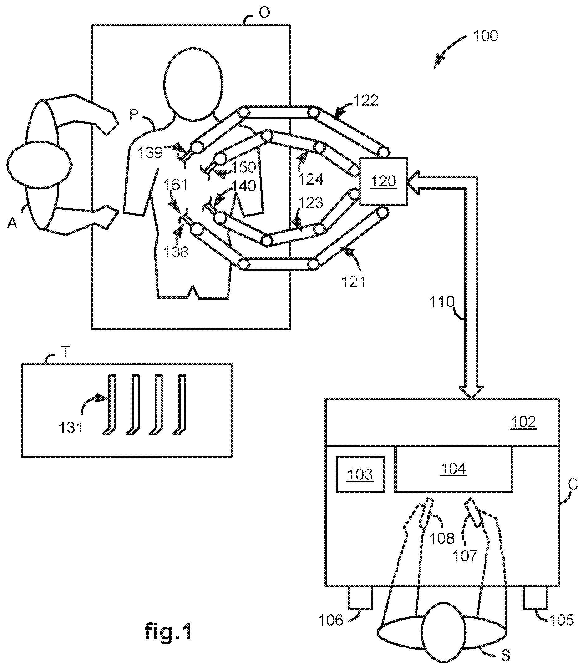
[0027] FIG. 1 illustrates a top view of an operating room employing a laparoscopic ultrasound robotic surgical system utilizing aspects of the present invention.
[0028] FIG. 2 illustrates a block diagram of a laparoscopic ultrasound robotic surgical system utilizing aspects of the present invention.
[0029] FIG. 3 illustrates a laparoscopic ultrasound probe utilizing aspects of the present invention.
[0030] FIG. 4 illustrates a flow diagram of a method for training a LUS robotic surgical system to robotically move a LUS probe in a trained manner upon command, utilizing aspects of the present invention.
[0031] FIG. 5 illustrates a flow diagram of a method for generating a clickable thumbnail image that allows a user to command that a LUS probe be automatically moved to a position and orientation from which the image was captured, utilizing aspects of the present invention.
[0032] FIG. 6 illustrates a flow diagram of a method for automatically moving s LUS probe to a position and orientation associated with a clickable thumbnail image, utilizing aspects of the present invention.
[0033] FIG. 7 illustrates a flow diagram of a method for robotically assisted needle guidance to a marked lesion of a cancerous structure, utilizing aspects of the present invention.
[0034] FIG. 8 illustrates a perspective view of a 3D ultrasound image of an anatomic structure in a camera reference frame with selectable 2D image slices as used in a medical robotic system utilizing aspects of the present invention.
[0035] FIG. 9 illustrates a perspective view of a 3D camera view of an anatomic structure in a camera reference as used in a medical robotic system utilizing aspects of the present invention.
[0036] FIG. 10 illustrates a perspective view of a frontal 2D slice of a 3D ultrasound view of an anatomic structure that overlays a 3D camera view of the anatomic structure, as displayable in a medical robotic system utilizing aspects of the present invention.
[0037] FIG. 11 illustrates a perspective view of an inner 2D slice of a 3D ultrasound view of an anatomic structure that overlays a 3D camera view of the anatomic structure, as displayable in a medical robotic system utilizing aspects of the present invention.
DETAILED DESCRIPTION OF THE PREFERRED EMBODIMENT
[0038] FIG. 1 illustrates, as an example, a top view of an operating room employing a robotic surgical system. The robotic surgical system in this case is a Laparascopic Ultrasound Robotic Surgical System 100 including a Console ("C") utilized by a Surgeon ("S") while performing a minimally invasive diagnostic or surgical procedure with assistance from one or more Assistants ("A") on a Patient ("P") who is reclining on an Operating table ("O").
[0039] The Console includes a Master Display 104 (also referred to herein as a "Display Screen") for displaying one or more images of a surgical site within the Patient as well as perhaps other information to the Surgeon. Also included are Master Input Devices 107 and 108 (also referred to herein as "Master Manipulators"), one or more Foot Pedals 105 and 106, a Microphone 103 for receiving voice commands from the Surgeon, and a Processor 102. The Master Input Devices 107 and 108 may include any one or more of a variety of input devices such as joysticks, gloves, trigger-guns, hand-operated controllers, or the like. The Processor 102 is preferably a personal computer that may be integrated into the Console or otherwise connected to it in a conventional manner.
[0040] The Surgeon performs a minimally invasive surgical procedure by manipulating the Master Input Devices 107 and 108 so that the Processor 102 causes their respectively associated Slave Arms 128 and 129 (also referred to herein as "Slave Manipulators") to manipulate their respective removably coupled and held Surgical Instruments 138 and 139 (also referred to herein as "Tools") accordingly, while the Surgeon views three-dimensional ("3D") images of the surgical site on the Master Display 104.
[0041] The Tools 138 and 139 are preferably Intuitive Surgical's proprietary EndoWristTM articulating instruments, which are modeled after the human wrist so that when added to the motions of the robot arm holding the tool, they allow a full six degrees of freedom of motion, which is comparable to the natural motions of open surgery. Additional details on such tools may be found in commonly owned U.S. Pat. No. 5,797,900 entitled "Wrist Mechanism for Surgical Instrument for Performing Minimally Invasive Surgery with Enhanced Dexterity and Sensitivity," which is incorporated herein by this reference. At the operating end of each of the Tools 138 and 139 is a manipulatable end effector such as a clamp, grasper, scissor, stapler, blade, needle, or needle holder.
[0042] The Master Display 104 has a high-resolution stereoscopic video display with two progressive scan cathode ray tubes ("CRTs"). The system offers higher fidelity than polarization, shutter eyeglass, or other techniques. Each eye views a separate CRT presenting the left or right eye perspective, through an objective lens and a series of mirrors. The Surgeon sits comfortably and looks into this display throughout surgery, making it an ideal place for the Surgeon to display and manipulate 3-D intraoperative imagery.
[0043] A Stereoscopic Endoscope 140 (also referred to as a "Laparoscope") provides right and left camera views to the Processor 102 so that it may process the information according to programmed instructions and cause it to be displayed on the Master Display 104. A Laparoscopic Ultrasound ("LUS") Probe 150 provides two-dimensional ("2D") ultrasound image slices of an anatomic structure to the Processor 102 so that the Processor 102 may generate a 3D ultrasound computer model of the anatomic structure and cause the 3D computer model (or alternatively, 2D "cuts" of it) to be displayed on the Master Display 104 as an overlay to the endoscope derived 3D images or within a Picture-in-Picture ("PIP") in either 2D or 3D and from various angles and/or perspectives according to Surgeon or stored program instructions.
[0044] Each of the Tools 138 and 139, as well as the Endoscope 140 and LUS Probe 150, is preferably inserted through a cannula or trocar (not shown) or other tool guide into the Patient so as to extend down to the surgical site through a corresponding minimally invasive incision such as Incision 166. Each of the Slave Arms 121-124 is conventionally formed of linkages which are coupled together and manipulated through motor controlled joints (also referred to as "active joints"). Setup Arms (not shown) comprising linkages and setup joints are used to position the Slave Arms 121-124 vertically and horizontally so that their respective surgical related instruments may be coupled for insertion into the cannulae.
[0045] The number of surgical tools used at one time and consequently, the number of slave arms being used in the System 100 will generally depend on the diagnostic or surgical procedure and the space constraints within the operating room, among other factors. If it is necessary to change one or more of the tools being used during a procedure, the Assistant may remove the tool no longer being used from its slave arm, and replace it with another tool, such as Tool 131, from a Tray ("T") in the Operating Room.
[0046] Preferably, the Master Display 104 is positioned near the Surgeon's hands so that it will display a projected image that is oriented so that the Surgeon feels that he or she is actually looking directly down onto the surgical site. To that end, an image of the Tools 138 and 139 preferably appear to be located substantially where the Surgeon's hands are located even though the observation points (i.e., that of the Endoscope 140 and LUS Probe 150) may not be from the point of view of the image.
[0047] In addition, the real-time image is preferably projected into a perspective image such that the Surgeon can manipulate the end effector of a Tool, 138 or 139, through its associated Master Input Device, 107 or 108, as if viewing the workspace in substantially true presence. By true presence, it is meant that the presentation of an image is a true perspective image simulating the viewpoint of an operator that is physically manipulating the Tools. Thus, the Processor 102 transforms the coordinates of the Tools to a perceived position so that the perspective image is the image that one would see if the Endoscope 140 was looking directly at the Tools from a Surgeon's eye-level during an open cavity procedure.
[0048] The Processor 102 performs various functions in the System 100. One important function that it performs is to translate and transfer the mechanical motion of Master Input Devices 107 and 108 to their associated Slave Arms 121 and 122 through control signals over Bus 110 so that the Surgeon can effectively manipulate their respective Tools 138 and 139. Another important function is to implement the various methods described herein providing a robotic assisted LUS capability.
[0049] Although described as a processor, it is to be appreciated that the Processor 102 may be implemented in practice by any combination of hardware, software and firmware. Also, its functions as described herein may be performed by one unit, or divided up among different components, each of which may be implemented in turn by any combination of hardware, software and firmware.
[0050] Prior to performing a minimally invasive surgical procedure, ultrasound images captured by the LUS Probe 150, right and left 2D camera images captured by the stereoscopic Endoscope 140, and end effector positions and orientations as determined using kinematics of the Slave Arms 121-124 and their sensed joint positions, are calibrated and registered with each other.
[0051] In order to associate the ultrasound image with the rest of the surgical environment, both need to be expressed in the same coordinate frame. Typically, the LUS Probe 150 is either labeled with markers and tracked by a tracking device such as the Optotrak.RTM. position sensing system manufactured by Northern Digital Inc. of Ontario, Canada, or held by a robot with precise joint encoders. Then the rigid transformation between the ultrasound image and the frame being tracked is determined (which is typically referred to as the ultrasound calibration).
[0052] For example, using the Optotrak.RTM. frame for the ultrasound calibration, the ultrasound image generated by the LUS Probe 150 is calibrated to an Optotrak.RTM. rigid body using an AX=XB formulation. "AX=XB" is a rubric for a class of calibration/registration problem commonly encountered in computer vision, surgical navigation, medical imaging, and robotics. The mathematical techniques are well known. See, e.g., E. Boctor, A. Viswanathan, M. Chioti, R. Taylor, G. Fichtinger, and G. Hager, "A Novel Closed Form Solution for Ultrasound Calibration," International Symposium on Biomedical Imaging, Arlington, Va, 2004, pp. 527-530.
[0053] "A" and "B" in this case, are transformations between poses of the Optotrak.RTM. rigid body (A) and the ultrasound image (B). Thus, "X" is the transformation from the ultrasound image to the rigid body.
[0054] To perform the ultrasound calibration, the LUS Probe 150 may be placed in three known orientations defined by the AX=XB calibration phantom. The ultrasound image frame may then be defined by three fiducials which appear in each of the three poses. The three poses allow three relative transformations based on Optotrak.RTM. readings (A) and three relative transformations based on the ultrasound images (B) for the AX=XB registration.
[0055] Camera calibration is a common procedure in computer vision applications. As an example, in order to determine the intrinsic and extrinsic parameters of the Endoscope 140, a checkerboard phantom with a multi-plane formulation provided by the Caltech Camera Calibration Toolbox may be used. To construct the phantom, Optotrak.RTM. markers are added to a typical checkerboard video calibration phantom, and each corner of the checkerboard is digitized using a calibrated Optotrak.RTM. pointer. Thus, the corner positions may be reported with respect to the Optotrak.RTM..
[0056] The calibration may then be performed by placing the phantom in view of the Endoscope 140 in several dozen orientations, and recording both stereo image data and Optotrak.RTM. readings of the four checkerboard corners. The images may then be fed into the calibration toolbox, which determines the intrinsic and extrinsic camera parameters, as well as the 3D coordinates of the grid corners in the camera frame. These coordinates may then be used with the Optotrak.RTM. readings to perform a point-cloud to point-cloud registration between the Endoscope 140 rigid body and camera frame.
[0057] The Controller 102 is configured to use the robot kinematics to report a coordinate frame for the LUS Probe 150 tip relative to the Endoscope 140. However, due to inaccuracies in the setup joint encoders, both of these coordinate frames may be offset from their correct values. Thus, it may be necessary to register the offsets between the real camera frame of the Endoscope 140 and the camera frame calculated from the kinematics as well as between the real and kinematic LUS Probe 150 frames. With this complete, the kinematics may be used in place of the Optotrak.RTM. readings to determine ultrasound image overlay placement.
[0058] As long as the position of the Endoscope 140 doesn't overly change, a constant transformation may be assumed between the kinematic tool tip and the laparoscopic Optotrak.RTM. rigid body. Using an AX=XB formulation, the LUS Probe 150 may be moved, for example, to several positions, and the static offset between the tool tip and Optotrak.RTM. rigid body registered. Knowing this offset, the Endoscope 140 offset may be calculated directly:
C.sub.CD=D.sub.LusD (C.sub.LusUrb).sup.-1T.sub.OUrb(T.sub.OErb).sup.-1F.sub.CErb (1)
[0059] where C.sub.CD is the camera offset from the real Endoscope 140 (also referred to herein simply as the "camera") frame to the camera frame calculated from the kinematics, F.sub.CErb is the transformation from the camera to the endoscope rigid body, T.sub.OUrb(T.sub.OErb).sup.-1 is the transformation from the camera rigid body to the LUS rigid body, C.sub.LusUrb is the transformation from the LUS rigid body to the kinematic ultrasound tool tip, and D.sub.LusD is the reading from the Controller 102 giving the transformation from the kinematic ultrasound tool tip to a fixed reference point associated with the Slave Arms 121-124.
[0060] However, the aforedescribed registration should be redone each time the camera is moved, thus making it best suited for pre-operative calibration and registration. For intra-operative, the registration may be better performed using video tracking of a visual marker on the LUS Probe 150 instead of the Optotrak.RTM. readings. Thus, if the camera were moved while using tool tracking, the registration can be corrected on the fly as the tool is tracked. For additional details on tool tracking, see, e.g., commonly owned U.S. patent application Ser. No. 11/130,471 entitled "Methods and system for performing 3-D tool tracking by fusion of sensor and/or camera derived data during minimally invasive surgery," filed May 16, 2005, which is incorporated herein by reference. In addition to, or alternatively, manual registration of ultrasound and camera images may be performed using conventional grab, move and rotate actions on a 3D ultrasound computer model of an anatomic structure, so that the computer model is properly registered over a camera model of the anatomic structure in the Master Display 104.
[0061] Slave Arms 123 and 124 may manipulate the Endoscope 140 and LUS Probe 150 in similar manners as Slave Arms 121 and 122 manipulate Tools 138 and 139. When there are only two master input devices in the system, however, such as Master Input Devices 107 and 108 in the System 100, in order for the Surgeon to manually control movement of either the Endoscope 140 or LUS Probe 150, it may be required to temporarily associate one of the Master Input Devices 107 and 108 with the Endoscope 140 or the LUS Probe 150 that the Surgeon desires manual control over, while its previously associated Tool and Slave Manipulator are locked in position.
[0062] FIG. 2 illustrates, as an example, a block diagram of the LUS Robotic Surgical System 100. In this system, there are two Master Input Devices 107 and 108. Master Input Device 107 controls movement of either a Tool 138 or a stereoscopic Endoscope 140, depending upon which mode its Control Switch Mechanism 211 is in, and Master Input Device 108 controls movement of either a Tool 139 or a LUS Probe 150, depending upon which mode its Control Switch Mechanism 231 is in.
[0063] The Control Switch Mechanisms 211 and 231 may be placed in either a first or second mode by a Surgeon using voice commands, switches physically placed on or near the Master Input Devices 107 and 108, Foot Pedals 105 and 106 on the Console, or Surgeon selection of appropriate icons or other graphical user interface selection means displayed on the Master Display 104 or an auxiliary display (not shown).
[0064] When Control Switch Mechanism 211 is placed in the first mode, it causes Master Controller 202 to communicate with Slave Controller 203 so that manipulation of the Master Input 107 by the Surgeon results in corresponding movement of Tool 138 by Slave Arm 121, while the Endoscope 140 is locked in position. On the other hand, when Control Switch Mechanism 211 is placed in the second mode, it causes Master Controller 202 to communicate with Slave Controller 233 so that manipulation of the Master Input 107 by the Surgeon results in corresponding movement of Endoscope 140 by Slave Arm 123, while the Tool 138 is locked in position.
[0065] Similarly, when Control Switch Mechanism 231 is placed in the first mode, it causes Master Controller 222 to communicate with Slave Controller 223 so that manipulation of the Master Input 108 by the Surgeon results in corresponding movement of Tool 139 by Slave Arm 122. In this case, however, the LUS Probe 150 is not necessarily locked in position. Its movement may be guided by an Auxiliary Controller 242 according to stored instructions in Memory 240. The Auxiliary Controller 242 also provides haptic feedback to the Surgeon through Master Input 108 that reflects readings of a LUS Probe Force Sensor 247. On the other hand, when Control Switch Mechanism 231 is placed in the second mode, it causes Master Controller 222 to communicate with Slave Controller 243 so that manipulation of the Master Input 222 by the Surgeon results in corresponding movement of LUS Probe 150 by Slave Arm 124, while the Tool 139 is locked in position.
[0066] Before switching back to the first or normal mode, the Master Input Device 107 or 108 is preferably repositioned to where it was before the switch to the second mode of Control Switch 211 or 231, as the case may be, or kinematic relationships between the Master Input Device 107 or 108 and its respective Tool Slave Arm 121 or 122 is readjusted so that upon switching back to the first or normal mode, abrupt movement of the Tool 138 or 139 does not occur. For additional details on control switching, see, e.g., commonly owned U.S. Pat. No. 6,659,939 "Cooperative Minimally Invasive Telesurgical System," which is incorporated herein by this reference.
[0067] The Auxiliary Controller 242 also performs other functions related to the LUS Probe 150 and the Endoscope 140. It receives output from a LUS Probe Force Sensor 247, which senses forces being exerted against the LUS Probe 150, and feeds the force information back to the Master Input Device 108 through the Master Controller 222 so that the Surgeon may feel those forces even if he or she is not directly controlling movement of the LUS Probe 150 at the time. Thus, potential injury to the Patient is minimized since the Surgeon has the capability to immediately stop any movement of the LUS Probe 150 as well as the capability to take over manual control of its movement.
[0068] Another key function of the Auxiliary Control 242 is to cause processed information from the Endoscope 140 and the LUS Probe 150 to be displayed on the Master Display 104 according to user selected display options. As will be described in more detail below, such processing includes generating a 3D ultrasound image from 2D ultrasound image slices received from the LUS Probe 150 through an Ultrasound Processor 246, causing either 3D or 2D ultrasound images corresponding to a selected position and orientation to be displayed in a picture-in-picture window of the Master Display 104, and causing either 3D or 2D ultrasound images of an anatomic structure to overlay a camera captured image of the anatomic structure being displayed on the Master Display 104.
[0069] Although shown as separate entities, the Master Controllers 202 and 222, Slave Controllers 203, 233, 223, and 243, and Auxiliary Controller 242 are preferably implemented as software modules executed by the Processor 102, as well as certain mode switching aspects of the Control Switch Mechanisms 211 and 231. The Ultrasound Processor 246 and Video Processor 236, on the other hand, are separate boards or cards typically provided by the manufacturers of the LUS Probe 150 and Endoscope 140 that are inserted into appropriate slots coupled to or otherwise integrated with the Processor 102 to convert signals received from these image capturing devices into signals suitable for display on the Master Display 104 and/or for additional processing by the Auxiliary Controller 242 before being displayed on the Master Display 104.
[0070] FIG. 3 illustrates a side view of one embodiment of the LUS Probe 150. The LUS Probe 150 is a dexterous tool with preferably two distal degrees of freedom, permitting reorientation of LUS Sensor 301 through, for example, approximately .+-.80.degree. in distal "pitch" and "yaw", and .+-.240.degree. in "roll" about a ball joint type, pitch-yaw mechanism 311 (functioning as and also referred to herein as a "Wrist" mechanism). Opposing pairs of Drive Rods or Cables (not shown) physically connected to a proximal end of the LUS Sensor 301 and extending through an internal passage of Elongated Shaft 312 mechanically control pitch and yaw movement of the LUS Sensor 301 using conventional push-pull type action. This flexibility of the LUS Probe 150 (provided by the pitch/yaw wrist mechanism) is especially useful in optimally orienting the LUS Probe 150 for performing ultrasonography on an anatomic structure during a minimally invasive surgical procedure.
[0071] The LUS Sensor 301 captures 2D ultrasound slices of a proximate anatomic structure, and transmits the information back to the Processor 102 through LUS Cable 304. Although shown as running outside of the Elongated Shaft 312, the LUS Cable 304 may also extend within it. A Clamshell Sheath 321 encloses the Elongate Shaft 312 and LUS Cable 304 to provide a good seal passing through a Cannula 331 (or trocar). Fiducial Marks 302 and 322 are placed on the LUS Sensor 301 and the Sheath 321 for video tracking purposes.
[0072] A force sensing capability is provided by Strain Gauges 303 which provide direct feedback of how hard the LUS Probe 150 is pushing on a structure being sonographed, supplementing whatever limited feedback is available from joint motor torques. Potential uses of this information include: providing a redundant safety threshold check warning the Surgeon or preventing motion into the structure if forces get too great; providing the Surgeon with an approved haptic appreciation of how hard he or she is pushing on a structure; and possibly permitting some measure of compensation for unmodeled deflections of the Pitch-Yaw or "Wrist" Mechanism 311 which are not detected for some reason by joint position sensors or encoders. The Strain Gauges 303 in this case serve the function of the LUS Probe Force Sensor 247 as previously described in reference to FIG. 2.
[0073] Robotic assisted LUS has the potential to reduce variability in the ultrasound images produced, compared to freehand scanning, and can reduce operator workload and difficulty. Behaviors as simple as rocking the LUS Probe 150 back and forth can maintain an updated 3D ultrasound image without operator intervention. More complicated behaviors can include movement of the LUS Probe 150 along the surface of a target anatomical structure in a methodical pattern to generate a full image of the target, or reliably returning to a previously scanned probe location and orientation.
[0074] FIG. 4 illustrates, as an example, a flow diagram of a method for training the Auxiliary Controller 242 (i.e., providing it with stored instructions) to cause the LUS Probe 150 to be robotically moved in the trained manner upon command, in order to capture a sequence of 2D ultrasound image slices of an anatomic structure, which are used by the Auxiliary Controller 242 to generate a 3D computer model of the structure. Prior to performing the training, the Control Switch Mechanism 231 is placed in its second mode so that the Surgeon may move the LUS Probe 150 for training purposes by manipulating the Master Input Device 108. After performing training, the Control Switch Mechanism 231 is then placed back into its first or normal mode so that the Surgeon may manipulate the Tool 139 to perform a minimally invasive surgical procedure using the Master Input Device 108.
[0075] In 401, the training module is initially idle (i.e., it is not being executed by the Processor 102). In 402, the Processor 102 (or a training module agent running in the background) may periodically check whether a start of training indication is received. Alternatively, the start of training indication may act as an interrupt which initiates running of the training module. The start of training indication may be initiated by a Surgeon through a recognized voice command, selection of a training option on a graphical user interface displayed on the Master Display 104, a switch mechanism that may physically be located on the corresponding Master Control Input 108 or other convenient location accessible to the Surgeon, or any other conventional means.
[0076] After the start of training indication is detected, in 403, the training module records or stores the current LUS Probe 150 position and orientation, and periodically (or upon Surgeon command) continues to do so by looping around 403 and 404 until a stop training indication is detected or received. The stop training indication in this case may also be initiated by the Surgeon in the same manner as the start of training indication, or it may be initiated in a different, but other conventional manner. After the stop training indication is detected or received, a last position and orientation of the LUS Probe 150 is recorded or stored.
[0077] Between the start and stop of training, the Surgeon moves the LUS Probe 150 and the Processor 102 stores its trajectory of points and orientations so that they may be retraced later upon command. In one type of training, the Surgeon moves the LUS Probe 150 back and forth near an anatomic structure in order to capture a sequence of 2D ultrasound image slices from which a 3D version (or computer model) of the anatomic structure may be rendered by the Processor 102. In another type of training, the Surgeon move the LUS Probe 150 once or more times along the surface of the anatomic structure in order to capture a different sequence of 2D ultrasound image slices from which a 3D version (or computer model) of the anatomic structure may be rendered by the Processor 102.
[0078] Although described as recording the positions and orientations of the LUS Probe 150, in practice, the active joint positions of its Slave Arm 124 are stored instead since their measurements are directly obtainable through encoders attached to each of the joints and their positions correspond to the LUS Probe 150 positions and orientations.
[0079] After storing the trajectory of positions and orientations of the LUS Probe 150 in the Memory 240, the trajectory is then associated with a means for the Surgeon to command the Auxiliary Controller 242 to move the LUS Probe 150 in the desired fashion. For example, the trajectory may be associated with a voice command which upon its detection, the Auxiliary Controller 242 causes the Slave Arm 124 to move the LUS Probe 150 back and forth along the stored trajectory of positions and orientations. Likewise, the trajectory may also be associated with a user selectable option on a graphical user interface displayed on the Master Display 104, or it may be associated with a switch mechanism such as a button or unused control element on the Master Input Device 108. It may also be associated with the depression of the Foot Pedal 106, so that the Auxiliary Controller 242 causes the Slave Arm 124 to move the LUS Probe 150 back and forth along the stored trajectory of positions and orientations as long as the Foot Pedal 106 is being depressed, and stops such motion once the Surgeon takes his or her foot off the Foot Pedal 106.
[0080] FIG. 5 illustrates, as an example, a flow diagram of a method for generating clickable thumbnail images corresponding to LUS Probe 150 positions and orientations that are stored in Memory 240, so that when the Surgeon clicks on one of the thumbnail images, the Auxiliary Controller 242 causes the Slave Arm 124 to move the LUS Probe 150 to its stored position and orientation. This allows the Surgeon to move the LUS Probe 150 to see different views of an anatomic structure while the Control Switch Mechanism 231 is in its first or normal mode. Thus, the Surgeon can continue to perform a minimally invasive surgical procedure by manipulating Tool 139 using the Master Input Device 108. The method may then be combined with that described in reference to FIG. 4 in order to generate a sequence of 2D ultrasound image slices starting from that position and orientation, from which the Auxiliary Controller 242 may generate a 3D computer model rendition of the anatomic structure.
[0081] Prior to performing the method, however, the Control Switch Mechanism 231 is placed in its second mode so that the Surgeon may move the LUS Probe 150 into the desired positions and orientations by manipulating the Master Input Device 108. After generating the clickable thumbnail images, the Control Switch Mechanism 231 is then placed back into its first or normal mode so that the Surgeon may manipulate the Tool 139 to perform the minimally invasive surgical procedure using the Master Input Device 108.
[0082] In 501, the Auxiliary Controller 242 receives a snapshot command from the Surgeon. The snapshot command may be, for example, a voice command, graphical user interface selection, or switch position. In 502, the Auxiliary Controller 242 causes the LUS Probe 150 to capture a 2D ultrasound image slice, and in 503, a thumbnail of the image is generated. The thumbnail in this case may include a simple JPEG or GIF file of the captured image. In 504, the current position and orientation of the LUS Probe 150 is stored in Memory 240 along with information of its association with the thumbnail. In 505, a clickable version of the thumbnail is displayed on the Master Display 104, so that the Surgeon may command the Auxiliary Controller 242 to cause the LUS Probe to be positioned and oriented at the stored position and orientation at any time upon clicking with his or her mouse or other pointing device on the clickable thumbnail. The Surgeon may then move the LUS Probe 150 to other positions and/or orientations, and repeat 501-505 to generate additional thumbnail images.
[0083] FIG. 6 illustrates, as an example, a flow diagram of a method for automatically moving the LUS Probe 150 to a position and orientation associated with a clickable thumbnail upon command to do so by a Surgeon while performing a minimally invasive surgical procedure using Tool 139. In 601, the clicking of a thumbnail generated by the method described in reference to FIG. 5 is detected by, for example, a conventional interrupt handling process. Upon such detection, in 602, the Auxiliary Controller 242 is instructed by, for example, stored instructions corresponding to the interrupt handling process, to retrieve the position and orientation stored in Memory 240 which is associated with the thumbnail. The Auxiliary Controller 242 then causes the LUS Probe 150 to move to that position and orientation by appropriately controlling Slave Arm 124. Thus, the Surgeon is able to move the LUS Probe 150 to a desired position without having to change modes of the Control Switch Mechanism 231 and halt operation of the Tool 139 until the LUS Probe 150 is moved.
[0084] FIG. 7 illustrates, as an example, a flow diagram of a method for robotically assisted needle guidance and penetration into a marked lesion of a cancerous structure, which allows appreciation for the aspects of robotic assisted LUS described herein. In 701, a selected 2D ultrasound image slice view of a cancerous structure such as a liver is displayed at the proper depth on the Master Display 104 as an overlay to a 3D camera view of the cancerous structure. The selected 2D ultrasound image slice view may be a frontal view or an inner slice view as taken from a previously generated 3D ultrasound computer model of the cancerous structure.
[0085] As an example clarifying the 701 process, FIG. 8 illustrates a simplified perspective view of a 3D ultrasound computer model 800 of the cancerous structure, which has been generated, for example, using the method described in reference to FIG. 4, and has been translated into the camera reference frame (EX, EY, EZ). FIG. 9, on the other hand, illustrates a simplified perspective view of a 3D camera view 900 of the cancerous structure as taken by the stereoscopic Endoscope 140. If the Surgeon selects a frontal slice 801 of the 3D ultrasound computer model 800 to be viewed as an overlay to the 3D camera view 900, then the overlay will appear as shown in FIG. 10. On the other hand, if the Surgeon selects one of the inner slices 802-804 of the 3D ultrasound computer model 800, such as inner slice 803, to be viewed as an overlay to the 3D camera view 900, then the overlay will appear as shown in FIG. 11 with the 2D ultrasound image slice 803 displayed at the proper depth. To avoid confusion, the portion of the 3D camera view above that depth is made transparent.
[0086] Alternatively, in 701, the surgeon may manually control movement of the LUS Probe 150 so that 2D ultrasound image slices captured by it appear as emanating in proper perspective and direction from the 3D camera image of the LUS Probe 150 in the Master Display 104. Preferably, the emanated 2D image slices being displayed in the Master Display 104 do not occlude the anatomic structure being probed. This manual approach may be particularly useful to the Surgeon for quickly spotting lesions in the anatomic structure.
[0087] In 702, the Surgeon marks lesions on the cancerous structure displayed as a result of 701. Each marked lesion is preferably marked using a designated color in order to clearly show that the Surgeon has already identified it, thereby avoiding double counting. The location in the camera reference frame (EX, EY, EZ) of each marked lesion is stored in Memory 240, and in 703, the Processor 102 determines an optimal needle tip path to that location.
[0088] In 703, the Processor 102 generates a virtual fixture to help guide the needle to the marked lesion. To generate the virtual fixture, local kinematic constraints on the Slave Arm manipulating the needle Tool may be specified by providing a table of constraints of the form:
({right arrow over (x)}-{right arrow over (x)}.sub.0).sup.T A.sub.K ({right arrow over (x)}-{right arrow over (x)}.sub.0)+{right arrow over (b)}.sub.K ({right arrow over (x)}-{right arrow over (x)}.sub.0).ltoreq.c (2)
[0089] where {right arrow over (x)} represents, in simplified terms, the current 6 DOF kinematic pose of a master arm, or, in more general terms, a parameterization of a Cartesian pose F linearized about some nominal pose F.sub.0 so that ({right arrow over (x)}-{right arrow over (x)}.sub.0) .about.F.sub.0.sup.-1 F. The tables are to be updated periodically based on visual feedback, user interaction, etc.
[0090] As can be appreciated, equation (2) can be easily checked and enforced.
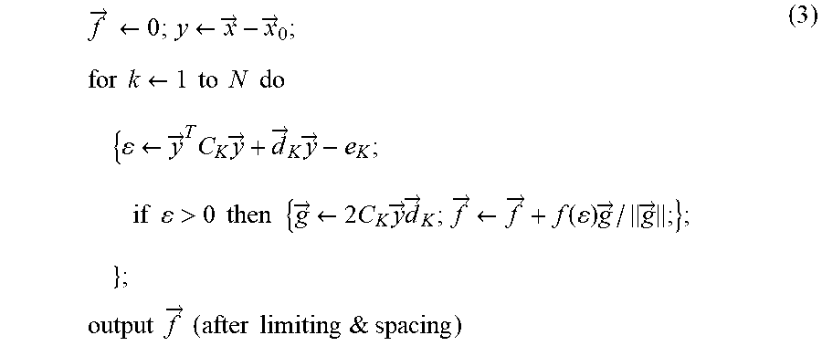
[0091] Similarly, a simple table-driven interface for surgeon interaction forces can be implemented approximately as follows:
f .fwdarw. .rarw. 0 ; y .rarw. x .fwdarw. - x .fwdarw. 0 ; ( 3 ) for k .rarw. 1 to N do { .rarw. y .fwdarw. T C K y .fwdarw. + d .fwdarw. K y .fwdarw. - e K ; if > 0 then { g .fwdarw. .rarw. 2 C K y .fwdarw. d .fwdarw. K ; f .fwdarw. .rarw. f .fwdarw. + f ( ) g .fwdarw. / g .fwdarw. ; } ; } ; output f .fwdarw. ( after limiting & spacing ) ##EQU00001##
[0092] where .epsilon. corresponds, roughly, to a distance from a surface in state space and the function f (.epsilon.) corresponds to a (non-linear) stiffness.
[0093] The above formulation suffices to support a variety of virtual chamfers, virtual springs, detents, etc. It is also easily extended to virtual dampers by adding velocity terms.
[0094] Now, more particularly, in the present case where it is desired to help aim an injection needle at a target in a live ultrasound image, let:
{right arrow over (P)}.sub.TROCAR=position where needle enters patient="RCM" point for needle insertion arm (4)
R.sub.NEEDLE=R.sub.0R({right arrow over (.alpha.)})=orientation of needle arm (5)
{right arrow over (.alpha.)}=vector representation for small rotation (6)
F.sub.LUS=[R.sub.LUS, {right arrow over (P)}.sub.LUS]=pose of LUS sensor (7)
V.sub.TARGET=position of target wrt LUS sensor (8)
[0095] Then the basic constraint is that the needle axis (which is assumed for this example to be the {right arrow over (Z)}axis of the needle driver) should be aimed at the target lesion, which will be given by F.sub.LUS {right arrow over (V)}.sub.TARGET. One metric for the aiming direction error will be:
AIMING ( .alpha. .fwdarw. ) = ( R NEEDLE z .fwdarw. ) .times. ( F LUS v .fwdarw. TARGET - P .fwdarw. TROCAR ) 2 = ( R ( .alpha. .fwdarw. ) z .fwdarw. ) .times. R 0 - 1 ( F LUS v .fwdarw. TARGET - P .fwdarw. TROCAR ) 2 ( 9 ) ##EQU00002##
[0096] which can be approximated as a quadratic form in {right arrow over (.alpha.)} and converted to a virtual fixture using the method described above. Similarly, if the position of the needle tip is {right arrow over (P)}.sub.TIP, the penetration depth beyond the LUS target will be given by:)
.epsilon..sub.BEYOND=(R.sub.0 R({right arrow over (.alpha.)}){right arrow over (z)})(F.sub.LUS {right arrow over (v)}.sub.TARGET-{right arrow over (P)}.sub.TIP) (10)
[0097] which can easily be transcribed into a virtual detent or barrier preventing over-penetration. Alternatively, a simple spherical attractor virtual fixture can be developed to minimize .parallel.F.sub.LUS {right arrow over (v)}.sub.TARGET-{right arrow over (P)}.sub.TIP.parallel..
[0098] In 705, the Processor 102 determines the needle tip position as it moves towards the target lesion, and in 706, the Processor 102 determines the distance between the needle tip position and the target lesion. The needle tip position may be determined from the Slave Arm kinematics and/or through visual tracking in the camera image.
[0099] In 707, the color of the lesion or some other object in the display changes as the needle tip gets closer to the target. For example, the color may start off as blue when the needle tip is still far away from the target, and it may change through color spectrum so that it becomes red as it nears the target. Alternatively, a bar graph or other visual indicator may be used to give a quick sense of the distance.
[0100] In 708, a determination is made whether the distance has reached a threshold distance (usually specified as some distance close to or even at the surface of the target lesion). If the threshold has not been reached, then the method loops back to 705 and continually repeats 705-708 until the threshold is reached. Once the threshold is reached, in 709, a 90 degree view of the cancerous structure and the approaching needle is shown in a picture-in-picture window of the Master Display 104. The method may then go back to 705 and repeat 705-708 as the needle penetrates the cancerous structure or withdraws back to its start position.
[0101] Although the various aspects of the present invention have been described with respect to a preferred embodiment, it will be understood that the invention is entitled to full protection within the full scope of the appended claims.
* * * * *
D00000
D00001
D00002
D00003
D00004
D00005
D00006
D00007
D00008
XML
uspto.report is an independent third-party trademark research tool that is not affiliated, endorsed, or sponsored by the United States Patent and Trademark Office (USPTO) or any other governmental organization. The information provided by uspto.report is based on publicly available data at the time of writing and is intended for informational purposes only.
While we strive to provide accurate and up-to-date information, we do not guarantee the accuracy, completeness, reliability, or suitability of the information displayed on this site. The use of this site is at your own risk. Any reliance you place on such information is therefore strictly at your own risk.
All official trademark data, including owner information, should be verified by visiting the official USPTO website at www.uspto.gov. This site is not intended to replace professional legal advice and should not be used as a substitute for consulting with a legal professional who is knowledgeable about trademark law.