Shoe Disinfecting Device
George; Dillon
U.S. patent application number 16/692040 was filed with the patent office on 2020-05-28 for shoe disinfecting device. The applicant listed for this patent is DG Technologies LLC. Invention is credited to Dillon George.
| Application Number | 20200163532 16/692040 |
| Document ID | / |
| Family ID | 70770079 |
| Filed Date | 2020-05-28 |


| United States Patent Application | 20200163532 |
| Kind Code | A1 |
| George; Dillon | May 28, 2020 |
SHOE DISINFECTING DEVICE
Abstract
A shoe disinfecting device is disclosed having a base which defines a central recess, a right side recess, and a left side recess. The central recess houses a central wiping which is held by a central frame. Side drying pads are also mounted within side recesses. A disinfecting liquid reservoir is removably mounted to the base. A manual liquid pump is coupled to the liquid reservoir and to nozzles positioned to direct a spray of liquid onto the central pad.
| Inventors: | George; Dillon; (Ooltewah, TN) | ||||||||||
| Applicant: |
|
||||||||||
|---|---|---|---|---|---|---|---|---|---|---|---|
| Family ID: | 70770079 | ||||||||||
| Appl. No.: | 16/692040 | ||||||||||
| Filed: | November 22, 2019 |
Related U.S. Patent Documents
| Application Number | Filing Date | Patent Number | ||
|---|---|---|---|---|
| 62771350 | Nov 26, 2018 | |||
| Current U.S. Class: | 1/1 |
| Current CPC Class: | A47L 23/24 20130101; A47L 23/22 20130101; A47L 23/04 20130101; A47L 23/263 20130101 |
| International Class: | A47L 23/26 20060101 A47L023/26; A47L 23/04 20060101 A47L023/04 |
Claims
1. A shoe disinfecting device comprising: a base having a first recess; a shoe wiping pad removably positioned within said first recess; a disinfecting liquid reservoir mounted within said base; a liquid pump in fluid communication with said disinfecting liquid reservoir, and at least one nozzle in fluid communication with said liquid pump and positioned to direct a spray of liquid from said at least one nozzle onto said shoe wiping pad.
2. The shoe disinfecting device of claim 1 wherein said liquid pump is a motorized liquid pump.
3. The shoe disinfecting device of claim 2 wherein said motorized liquid pump includes an activation switch positioned closely adjacent to said first recess.
4. The shoe disinfecting device of claim 1 wherein said liquid pump is a manually actuated pump.
5. The shoe disinfecting device of claim 4 wherein said manually actuated pump includes a pump cylinder, a reciprocating piston coupled to said pump cylinder, and a push button coupled to said reciprocating piston positioned to engage a user's foot stepping upon said push button for forcible movement of said reciprocating piston.
6. The shoe disinfecting device of claim 1 wherein said base further includes a second recess, and a first drying pad positioned within said second recess.
7. The shoe disinfecting device of claim 6 wherein said base further includes a third recess, and a second drying pad positioned within said third recess, wherein said first recess is positioned between said second recess and said third recess.
8. The shoe disinfecting device of claim 1 further comprising holding means for holding said shoe wiping pad securely within said first recess.
9. The shoe disinfecting device of claim 8 wherein said holding means is a frame extending about a periphery of said shoe wiping pad.
10. The shoe disinfecting device of claim 8 wherein said holding means is a mating pair of hook and loop type fasteners.
11. A shoe disinfecting device comprising: a base; a shoe wiping pad removably coupled to said base; a disinfecting liquid reservoir coupled to said base; a liquid pump in fluid communication with said disinfecting liquid reservoir, and at least one nozzle in fluid communication with said liquid pump and positioned to spray liquid onto said shoe wiping pad.
12. The shoe disinfecting device of claim 11 wherein said liquid pump is a motorized liquid pump.
13. The shoe disinfecting device of claim 12 wherein said motorized liquid pump includes an activation switch positioned closely adjacent to said shoe wiping pad.
14. The shoe disinfecting device of claim 11 wherein said liquid pump is a manually actuated pump.
15. The shoe disinfecting device of claim 14 wherein said manually actuated pump includes a pump cylinder, a reciprocating piston coupled to said pump cylinder, and a push button coupled to said reciprocating piston positioned to engage a user's foot stepping upon said push button for forcible movement of said reciprocating piston.
16. The shoe disinfecting device of claim 11 further comprising a first drying pad.
17. The shoe disinfecting device of claim 16 wherein said base further includes a second drying pad, wherein said shoe wiping pad is positioned between said first drying pad and said second drying pad.
18. The shoe disinfecting device of claim 11 further comprising holding means for holding said shoe wiping pad securely to said base.
19. The shoe disinfecting device of claim 18 wherein said holding means is a frame extending about a periphery of said shoe wiping pad.
20. The shoe disinfecting device of claim 8 wherein said holding means is a mating pair of hook and loop type fasteners.
Description
CROSS REFERENCE TO RELATED APPLICATIONS
[0001] This application claims the benefit of U.S. Provisional Patent Application No. 62/771,350 filed Nov. 26, 2018 and entitled "Shoe Disinfecting Device", and is incorporated herein by reference.
STATEMENT REGARDING FEDERALLY SPONSORED RESEARCH OR DEVELOPMENT
[0002] Not applicable.
THE NAMES OF THE PARTIES TO A JOINT RESEARCH AGREEMENT
[0003] Not applicable.
TECHNICAL FIELD
[0004] The present disclosure relates to the field of disinfecting devices. More particularly, the disclosure relates to a disinfecting device which is utilized to disinfect the bottom of a shoe.
BACKGROUND OF THE INVENTION
[0005] The bottoms of shoes come into direct contact with all types of unclean substances commonly found on a floor, street, sidewalk or other walking surface. Many of these substances are riddled with bacteria or unsanitary matter. As a person walks into his or her home, these unclean substances are tracked onto the floor of the home. Any person walking or crawling on the floor now comes into direct contact with these unclean substances, therefore posing a serious health risk to that person.
[0006] Accordingly, a need exists for an easily to use device that provides a manner of sanitizing the shoe in an easy and effective manner.
[0007] This section is intended to introduce various aspects of the art, which may be associated with exemplary embodiments of the present disclosure. This discussion is believed to assist in providing a framework to facilitate a better understanding of particular aspects of the present disclosure. Accordingly, it should be understood that this section should be read in this light, and not necessarily as admissions of prior art.
BRIEF SUMMARY OF THE INVENTION
[0008] A shoe disinfecting device is provided herein. In one embodiment, the shoe disinfecting device includes a base having a first recess, a shoe wiping pad removably positioned within the first recess, a disinfecting liquid reservoir mounted within the base, a liquid pump in fluid communication with the disinfecting liquid reservoir, and at least one nozzle in fluid communication with the liquid pump and positioned to direct a spray of liquid from the at least one nozzle onto the shoe wiping pad.
BRIEF DESCRIPTION OF THE DRAWINGS
[0009] So that the manner in which the present inventions can be better understood, certain illustrations, charts and/or flow charts are appended hereto. It is to be noted, however, that the drawings illustrate only selected embodiments of the inventions and are therefore not to be considered limiting of scope, for the inventions may admit to other equally effective embodiments and applications.
[0010] FIG. 1 is a perspective view of the shoe disinfecting device embodying principles of the invention.
[0011] FIG. 2 is a cross-sectional side view of the shoe disinfecting device of FIG. 1, shown in a first, extended position.
[0012] FIG. 3 is a cross-sectional side view of the shoe disinfecting device of FIG. 1, shown in a second, depressed position.
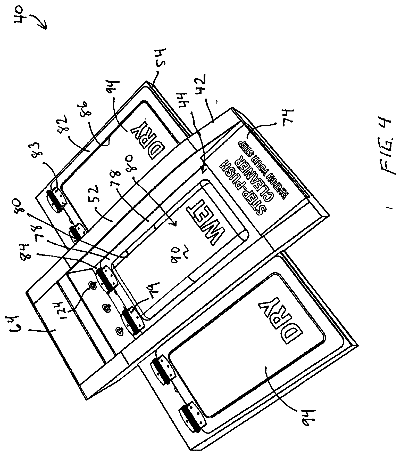
[0013] FIG. 4 is a perspective view of the shoe disinfecting device embodying principles of the invention in another form.
[0014] FIG. 5 is an exploded, perspective view of the shoe disinfecting device of FIG. 4.
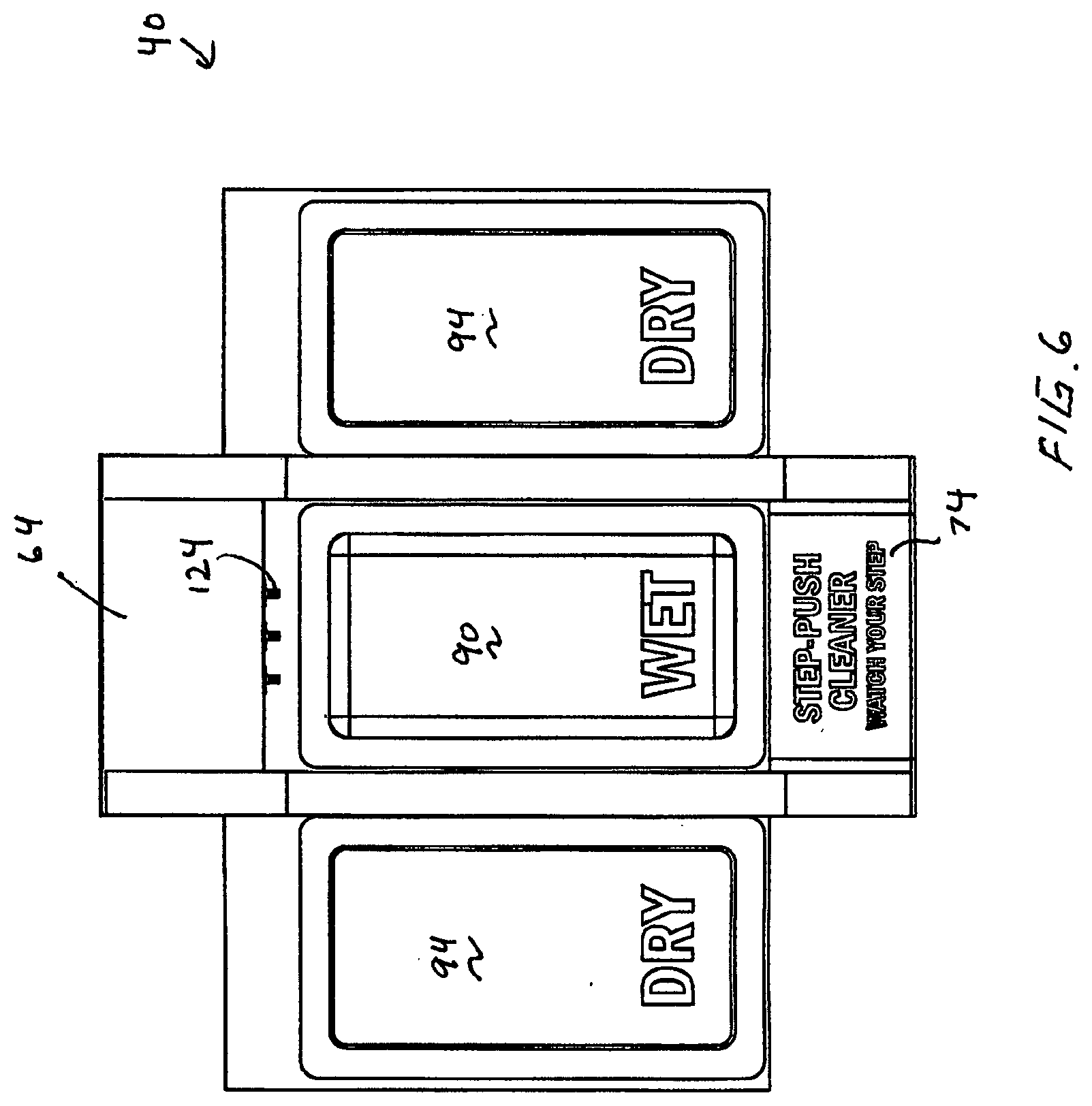
[0015] FIG. 6 is a top view of the shoe disinfecting device of FIG. 4.
[0016] FIG. 7 is a front view of the shoe disinfecting device of FIG. 4.
[0017] FIG. 8 is a right side view of the shoe disinfecting device of FIG. 4.
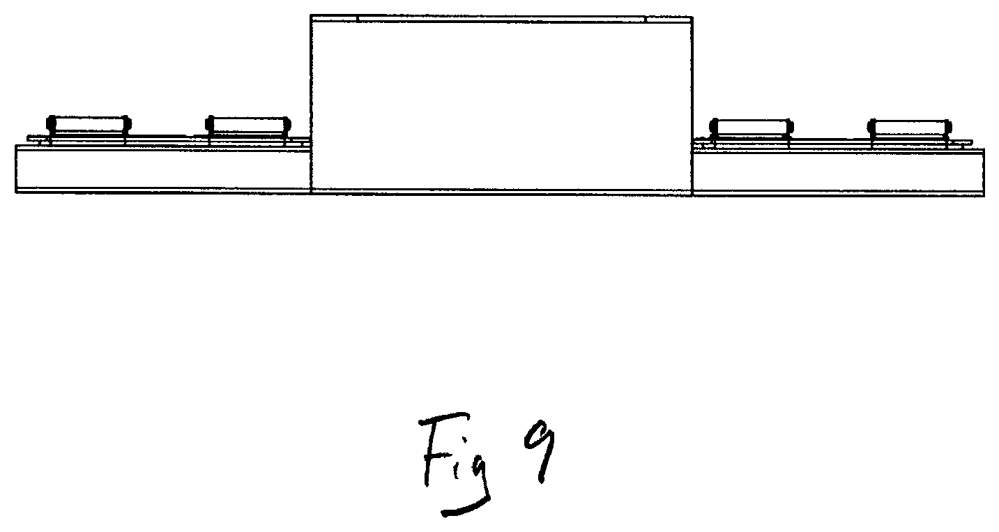
[0018] FIG. 9 is a rear view of the shoe disinfecting device of FIG. 4.
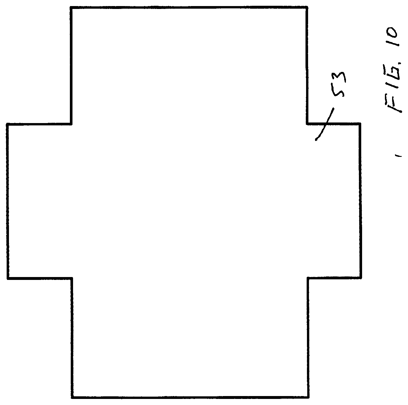
[0019] FIG. 10 is a bottom view of the shoe disinfecting device of FIG. 4.
[0020] FIG. 11 is an exploded, perspective view of the shoe disinfecting device embodying principles of the invention in another form.
DETAILED DESCRIPTION OF CERTAIN EMBODIMENTS
Definitions
[0021] For purposes of the present disclosure, it is noted that spatially relative terms, such as "up," "down," "right," "left," "beneath," "below," "lower," "above," "upper" and the like, may be used herein for ease of description to describe one element or feature's relationship to another element(s) or feature(s) as illustrated in the figures. It will be understood that the spatially relative terms are intended to encompass different orientations of the device in use or operation in addition to the orientation depicted in the figures. For example, if the device in the figures is turned over or rotated, elements described as "below" or "beneath" other elements or features would then be oriented "above" the other elements or features. Thus, the exemplary term "below" can encompass both an orientation of above and below. The device may be otherwise oriented (rotated 90 degrees or at other orientations) and the spatially relative descriptors used herein interpreted accordingly.
DESCRIPTION OF SELECTED SPECIFIC EMBODIMENTS
[0022] FIGS. 1-3 show a shoe disinfecting device, under an embodiment. With reference to the drawings, the shoe disinfecting device 10 has a generally rectangular shaped base 12. The base 12 has peripheral side walls 14 extending upwardly from a floor 16. The base 12 is configured to hold a liquid disinfecting solution S, such as an alcohol, propanol, benzalkonium chloride, triclosan or similar commonly available disinfectants.
[0023] The shoe disinfecting device 10 also includes a lid or platform 20 which is configured to fit within the base 12 for relative vertical movement therebetween. The lid 20 includes a series of liquid holes, nozzles, or passages 22 extending there through. The lid 20 has an upper surface 24 having a rough texture provided by a series of upright bristles, ridges or randomly oriented fibers 26. A liquid storage reservoir or compartment 27 is formed from the combination of the base 12 and lid 20, which also acts as a pump when actuated.
[0024] The lid 20 is spring loaded so that the lid is biased upwardly from a depressed position, shown in FIG. 3, towards an extended position, shown in FIG. 2. The spring loading may be accomplished through any conventional manner, such as with coil springs, flat springs, blocks of resilient rubber, compressible material, or the like, but is shown as a compressible block of material 28 in the drawings. The return motion of the lid may create a vacuum within the base 12 which pulls back any liquid remaining on top of the lid's upper surface 24.
[0025] The shoe disinfecting device 10 also includes a side tray 30 to which is mounted a removable or disposable wiping cloth 32. The side tray 30 may be fixed in position or may be movable so as to retract within the base 12 when stowed or not in use.
[0026] In use, a quantity of disinfecting solution S is placed within the base 12 so that it rises to the appropriate initial level within the base 12. With the disinfecting solution S filled to this level, the lid 20 is then positioned into the base 12 atop the disinfecting solution S.
[0027] When a person places his or her foot upon the upper surface 24 of the lid 20, the force causes the lid 20 to move downwardly from its extended position and towards its depressed position. This downward motion of the lid 20 pressurizes the disinfecting solution S causing the disinfecting solution to be pumped or expelled through the passages 22 in the lid 20. The expelled disinfecting solution preferably covers the bristles 26 of the lid 20. The downward motion of the lid 20 also compresses the spring 28, shown as compressed, resilient material in FIG. 3.
[0028] Any motion of the person's shoe upon the lid 20 causes the disinfecting solution S, and especially the disinfecting solution S upon the bristles 26, to be worked over the bottom surface of the shoe or shoe's sole. The bristles 26 aid in enabling the disinfecting solution S to be worked into any small crevices within the shoe's bottom surface.
[0029] The release of the shoe from the lid 20 causes the lid 20 to move back to its extended position through the biasing force of the spring 28.
[0030] Once the shoe has been treated through placement upon the disinfecting liquid saturated lid 20, the person may then position the bottom surface of the shoe upon the wiping cloth 32 coupled to the side tray 30. This placement of the shoe removes any excess disinfecting solution S present upon the bottom surface of the shoe.
[0031] Once the wiping cloth 32 has become sufficiently soiled, it may be removed and washed, or it may be replaced by another similar wiping cloth 32.
[0032] With reference next to FIGS. 4-10, there is shown a shoe disinfecting device 40 constructed in accordance with another embodiment of the present invention. Here, the shoe disinfecting device 40 includes a base 42 which defines three separate recesses, specifically, a central recess 44, a right side recess 46, and a left side recess 48. The central recess 40 is defined by central side walls 52 and floor 53. The side recesses 46 and 48 are partially defined by central side walls 52, ancillary side walls 54 and floors 55. The floors 53 and 55 are shown incorporated into a generally cross shaped bottom plate 56 which is coupled to the bottom of the base 42.
[0033] The base 42 also includes a rear wall 58 and an interior end wall 60 which in combination with central side walls 52 define a liquid container storage compartment 62. The liquid container storage compartment 62 also includes a pivotal or removable cover or lid 64.
[0034] The base 42 also includes a front wall 68 and a second interior end wall 70 which in combination with the central side walls 52 define a pump storage compartment 72. The pump storage compartment 72 also includes a pivotal or reciprocating push button, cover or lid 74.
[0035] A central frame 78 is pivotally coupled to a lower stepped area 84 of the interior end wall 60 through hinges 79 for pivotal movement between an open configuration and a closed configuration in register with the central recess 44. The central frame 78 is a peripheral frame with a large central opening 80 therethrough, as best shown in FIG. 4. Similarly, the right and left side recesses 46 and 48 have overlying side frames 82 pivotally coupled to the ancillary side walls 54 through hinges 83 for pivotal movement between an open configuration and a closed configuration. The side frames 82 also have central openings 86.
[0036] The shoe disinfecting device 40 includes a central wiping or scrubbing cloth or pad 90 removably positioned upon the floor 53 of the central recess 44. The central pad 90 may be made of any material which is suitable for accepting a cleaning solution and scrubbing or cleaning the bottom of a shoe. The central pad 90 may include bristles, nubs, or projections to aid in removing dirt within the sole of a shoe. The central frame 78 overlays the peripheral margin of the cleaning pad 90 to maintain the position of the cleaning pad 90 during use. Similarly, a side drying pads 94 are removably positioned upon the floor 55 of the right and left side recesses 46 and 48. The side drying pads 94 are made of any material which is suitable for drying the bottom of a shoe upon contact with the drying pad 94.
[0037] A removable disinfecting liquid container or reservoir 98 is removably positioned within the liquid container storage compartment 62. The reservoir 98 includes a removable cap 100 and a liquid dispending stem 102.
[0038] A manual liquid pump 106 is positioned within the pump storage compartment 72. The liquid pump 106 includes a pump base 108, a pair of pump cylinders 110, and a pair of reciprocating pistons 112 having O-ring seals 114. The pump pistons 112 are spring biased from a lower, compressed position to an upper decompressed position by a set of three springs 116 associated with each piston 112.
[0039] A liquid feed tube 120 extends between the reservoir stem 102 and the liquid pump 106 so that liquid disinfectant can flow from the reservoir 98 to the inlet of the pump 106. Three liquid dispensing tubes 122 extend between the outlet of the pump 106 and three corresponding liquid spray nozzles 124 mounted to the interior end wall 60 and positioned to direct a spray of liquid onto the central pad 90.
[0040] In use, a disinfecting liquid or solution is stored within the liquid reservoir 98. Upon a person approaching the location of the shoe disinfecting device 40, the person steps down upon the push button lid 74, which forces the lid 74 to pivot downwardly thereby moving the pump pistons 112 within the pump cylinders 110, i.e., compressing the pump. The compression of the pump 106 causes liquid to be expelled from the pump 106, through the dispensing tubes 122, and through the spray nozzles 124 onto the adjacent central pad 90, so that the central pad 90 is coated, saturated with, or wetted with the disinfecting solution. It should be understood that the number, arrangement, and pattern of spray produced by the nozzles may be different from that shown in the preferred embodiment, for example, there may be one to four nozzles, or the nozzles may be arranged along either one or both sides of the central recess 44.
[0041] The release of the lid 74 causes the pump springs 116 to force the pump pistons 112 upwardly to their initial decompressed positions. This return motion of the pump pistons causes a suction through the pump 106 and feed tube 120 which creates a flow of disinfecting liquid from the reservoir 98 to the pump 106. Alternatively, the disinfecting liquid may gravitationally flow from the reservoir 98 to the pump 106 without the need of negative pressure.
[0042] With the central pad 90 now having the disinfecting liquid upon it, the person then wipes his or her shoes across the top surface of the central pad 90. The person may also wipe his or her shoes across the adjacent side dry pad 94 to dry off the shoe. The bottom or sole of the shoe is now disinfected.
[0043] With reference next to FIG. 11, there is shown a shoe disinfecting device 140 constructed in accordance with another embodiment of the present invention. Here, the shoe disinfecting device 140 includes a base 142 which defines three separate recesses, specifically, a central recess 144, a right side recess 146, and a left side recess 148. The central recess 144 is defined by central side walls 152 and floor 153. The side recesses 146 and 148 are partially defined by central side walls 152, ancillary side walls 154 and floors 155. The floors 153 and 155 are shown incorporated into a generally cross shaped bottom plate 156 which is coupled to the bottom of the base 142.
[0044] The base 142 also includes a rear wall 158 and an interior end wall 160 which in combination with central side walls 152 define a liquid container storage compartment 162. The liquid container storage compartment 162 also includes a pivotal or removable cover or lid 164.
[0045] The base 142 also includes a front wall 168 and a second interior end wall 170 which in combination with the central side walls 152 define a pump storage compartment 172. The pump storage compartment 172 also includes a pivotal or reciprocating push button, cover or lid 174.
[0046] The shoe disinfecting device 140 includes a central wiping cloth or pad 190 removably positioned upon a perforated drain platform 186 positioned over the floor 153 of the central recess 144. The central pad 190 may be made of any material which is suitable for accepting a cleaning solution and scrubbing or cleaning the bottom of a shoe. The central pad 190 may include bristles, nubs, or projections to aid is removing dirt within the sole of a shoe. The frame or hook and loop type fasteners 188 is mounted to the central pad 190 and drain platform 186 to releasably hold the central pad 190 to maintain the position of the cleaning pad 190 during use. Note that the fastener 188 may comprise an adhesive surface for attaching to central pad 190 and/or drain platform 186. Similarly, side drying pads 194 are removably positioned upon a perforated drain platform 195 positioned over the floor 155 of the right and left side recesses 146 and 148. The side drying pads 194 are made of any material which is suitable for drying the bottom of a shoe upon contact with the drying pad 194. Side hook and loop type fasteners 196 are mounted to the side pads 194 and drain platforms 195 to maintain the position of the dry pads 194 during use. Note that the fasteners 196 may comprise an adhesive surface for attaching to side drying pads 194 and/or drain platform 195. The perforated drain platforms 186 and 195 provide for better airflow below the pads 190 and 194 to promote faster drying after use. The drain platforms 186, 195 may comprise perforated metal. The central pad 190 may comprise a series of 0.25'' L.times.0.25'' W.times.0.375'' H Foam Posts. The side drying pads 194 may comprise 0.5'' H pile Microfiber. The foam posts may be square or round, triangular, quadrilateral, hexagonal or octagonal or truncated, extruded polygons or pyramids to a point to help saturate the vertical surfaces of the texture or tread of the shoe.
[0047] A removable disinfecting liquid container or reservoir 198 is removably positioned within the liquid container storage compartment 162. The reservoir 198 includes a removable cap 200 and a liquid dispending stem 202.
[0048] An electric liquid pump 206 is positioned within the pump storage compartment 172. The liquid pump 206 is coupled to a PCB controller 208 which is coupled to a battery pack 210. The controller 208 is coupled to an electronic switch 212 which controls the actuation of the electric pump 206.
[0049] A liquid feed tube 220 extending between the reservoir stem 202 and the liquid pump 206 so that liquid disinfectant can flow from the reservoir 198 to the inlet of the pump 206. Three liquid dispensing tubes 222 extend between the outlet of the pump 206 and three corresponding liquid spray nozzles 224 mounted to the interior end wall 160 and positioned to direct a spray of liquid onto the central pad 190.
[0050] In use, a disinfecting liquid or solution is stored within the liquid reservoir 198. Upon a person approaching the location of the shoe disinfecting device 140, the person steps down upon the push button lid 174, which forces the lid 174 to pivot downwardly thereby actuating the electronic switch 212 to activate the electric pump 206 through controller 208. The activation of the pump 206 causes liquid to be expelled from the pump 206, through the dispensing tubes 222, and through the spray nozzles 224 onto the adjacent central pad 190 so that the central pad 190 is coated, saturated with, or wetted with the disinfecting solution. It should be understood that the number, arrangement, and pattern of spray produced by the nozzles may be different from that shown in the preferred embodiment, for example, there may be one to four nozzles, or the nozzles may be arranged along either one or both sides of the central recess 144. Also, the controller 208 controls the actuation of the pump for a preselected time period to prevent oversaturation. Note that a proximity or motion sensor attached to a shoe disinfecting device may detect proximity of a user and activate the electric pump.
[0051] With the central pad 190 now having the disinfecting liquid upon it, the person then wipes his or her shoes across the top surface of the central pad 190. The person may also wipe his or her shoes across the adjacent side dry pad 194 to dry off the shoe. The bottom or sole of the shoe is now disinfected.
[0052] As shown in FIGS. 5 and 11 the overall wet pad to dry pad configuration may be side to side. However the configuration may be front to back so the user walks on the wet pad and steps forward to the dry pad as to not re-contaminate the already cleaned shoe. Under an embodiment a vertical support (or grip handles) may extend from the base of a shoe disinfecting device up 36-46'' to help user balance while using the device.
[0053] It should be understood that other means for maintaining the positions of the central pad and/or side drying pads, such as with adhesive strips, clamps, pinch bars, etc.
[0054] A shoe disinfecting device is described comprising under an embodiment a base having a first recess, a shoe wiping pad removably positioned within said first recess, a disinfecting liquid reservoir mounted within said base, a liquid pump in fluid communication with said disinfecting liquid reservoir, and at least one nozzle in fluid communication with said liquid pump and positioned to direct a spray of liquid from said at least one nozzle onto said shoe wiping pad.
[0055] The liquid pump of an embodiment is a motorized liquid pump.
[0056] The motorized liquid pump of an embodiment includes an activation switch positioned closely adjacent to said first recess.
[0057] The liquid pump of an embodiment is a manually actuated pump.
[0058] The manually actuated pump of an embodiment includes a pump cylinder, a reciprocating piston coupled to said pump cylinder, and a push button coupled to said reciprocating piston positioned to engage a user's foot stepping upon said push button for forcible movement of said reciprocating piston.
[0059] The base of an embodiment further includes a second recess, and a first drying pad positioned within said second recess.
[0060] The base of an embodiment further includes a third recess, and a second drying pad positioned within said third recess, wherein said first recess is positioned between said second recess and said third recess.
[0061] The shoe disinfecting device of an embodiment comprises holding means for holding said shoe wiping pad securely within said first recess.
[0062] The holding means of an embodiment is a frame extending about a periphery of said shoe wiping pad.
[0063] The holding means of an embodiment is a mating pair of hook and loop type fasteners.
[0064] A shoe disinfecting device is described herein comprising under an embodiment a base, a shoe wiping pad removably coupled to said base, a disinfecting liquid reservoir coupled to said base, a liquid pump in fluid communication with said disinfecting liquid reservoir, and at least one nozzle in fluid communication with said liquid pump and positioned to spray liquid onto said shoe wiping pad.
[0065] The liquid pump of an embodiment is a motorized liquid pump.
[0066] The motorized liquid pump of an embodiment includes an activation switch positioned closely adjacent to said shoe wiping pad.
[0067] The liquid pump of an embodiment is a manually actuated pump.
[0068] The manually actuated pump of an embodiment includes a pump cylinder, a reciprocating piston coupled to said pump cylinder, and a push button coupled to said reciprocating piston positioned to engage a user's foot stepping upon said push button for forcible movement of said reciprocating piston.
[0069] The shoe disinfecting device of an embodiment further comprises a first drying pad.
[0070] The base of an embodiment further includes a second drying pad, wherein said shoe wiping pad is positioned between said first drying pad and said second drying pad.
[0071] The shoe disinfecting device of an embodiment further comprises holding means for holding said shoe wiping pad securely to said base.
[0072] The holding means of an embodiment is a frame extending about a periphery of said shoe wiping pad.
[0073] The holding means of an embodiment is a mating pair of hook and loop type fasteners.
[0074] Variations of the shoe disinfecting device may fall within the spirit of the claims, below. It will be appreciated that the inventions are susceptible to modification, variation, and change without departing from the spirit thereof.
* * * * *
D00000
D00001
D00002
D00003
D00004
D00005
D00006
D00007
D00008
D00009
D00010
XML
uspto.report is an independent third-party trademark research tool that is not affiliated, endorsed, or sponsored by the United States Patent and Trademark Office (USPTO) or any other governmental organization. The information provided by uspto.report is based on publicly available data at the time of writing and is intended for informational purposes only.
While we strive to provide accurate and up-to-date information, we do not guarantee the accuracy, completeness, reliability, or suitability of the information displayed on this site. The use of this site is at your own risk. Any reliance you place on such information is therefore strictly at your own risk.
All official trademark data, including owner information, should be verified by visiting the official USPTO website at www.uspto.gov. This site is not intended to replace professional legal advice and should not be used as a substitute for consulting with a legal professional who is knowledgeable about trademark law.