Rack Assembly
CHEN; Hsin-Yueh
U.S. patent application number 16/203107 was filed with the patent office on 2020-05-28 for rack assembly. This patent application is currently assigned to I JANG INDUSTRIAL CO., LTD.. The applicant listed for this patent is I JANG INDUSTRIAL CO., LTD.. Invention is credited to Hsin-Yueh CHEN.
| Application Number | 20200163470 16/203107 |
| Document ID | / |
| Family ID | 70769825 |
| Filed Date | 2020-05-28 |


| United States Patent Application | 20200163470 |
| Kind Code | A1 |
| CHEN; Hsin-Yueh | May 28, 2020 |
RACK ASSEMBLY
Abstract
A rack assembly has two side racks, two rails, and at least one sub-rack. The rails are mounted between the side racks and include a front rail and a rear rail parallel with each other. Each rail has an opening in a bottom of the rail. The at least one sub-rack is slidable along the rails and each sub-rack has a rack frame, a connection rod, and at least one supporting member. The rack frame has at least one front rod and at least one rear rod. Each front rod has an extension rod mounted retractably on a top of the front rod and having a front wheel.
| Inventors: | CHEN; Hsin-Yueh; (Changhua County, TW) | ||||||||||
| Applicant: |
|
||||||||||
|---|---|---|---|---|---|---|---|---|---|---|---|
| Assignee: | I JANG INDUSTRIAL CO., LTD. Changhua County TW |
||||||||||
| Family ID: | 70769825 | ||||||||||
| Appl. No.: | 16/203107 | ||||||||||
| Filed: | November 28, 2018 |
| Current U.S. Class: | 1/1 |
| Current CPC Class: | A47F 5/0093 20130101; A47B 47/0091 20130101; A47F 5/01 20130101; A47F 5/0018 20130101; A47B 55/02 20130101 |
| International Class: | A47F 5/00 20060101 A47F005/00; A47B 47/00 20060101 A47B047/00; A47B 55/02 20060101 A47B055/02; A47F 5/01 20060101 A47F005/01 |
Claims
1. A rack assembly comprising: two side racks spaced from each other; two rails mounted between and connected with the side racks, being parallel with each other, located at a same height, and including a front rail and a rear rail, and each rail having a U-section to form an opening in a bottom of the rail, wherein each rail comprises a bottom panel, an outer panel, and an inner panel; the outer panel and the inner panel are respectively formed on and extend downwardly from two sides of the bottom panel; the inner panels of the two rails face each other; and the inner panel has a downward extension length larger than a downward extension length of the outer panel; and at least one sub-rack disposed between the side racks, being slidable along the rails, and each one of the at least one sub-rack comprising a rack frame composed of multiple longitudinal rods, which include at least one front rod and at least one rear rod corresponding in position respectively to the front rail and the rear rail, wherein each one of the at least one front rod has an extension rod mounted retractably on a top of the front rod and having a front wheel mounted rotatably on a top of the extension rod; and a spring mounted in the front rod and abutting a bottom of the extension rod to push the extension rod upward and to hold the front wheel on the extension rod in the front rail; a connection rod connected to the extension rod of each one of the at least one front rod; and at least one supporting member mounted on the rack frame.
2. The rack assembly as claimed in claim 1, wherein each side rack comprises a rack frame composed of multiple longitudinal rods and at least one supporting member mounted securely on the rack frame of the side rack.
3. The rack assembly as claimed in claim 2, wherein each one of the at least one sub-rack further comprises a pulling rod mounted on the connection rod of the sub-rack.
4. The rack assembly as claimed in claim 3, wherein each longitudinal rod of each one of the at least one sub-rack has a bottom and a rotating wheel mounted on the bottom of the longitudinal rod of the sub-rack.
5. The rack assembly as claimed in claim 1, wherein each one of the at least one sub-rack further comprises a pulling rod mounted on the each connection rod of the each sub-rack.
6. The rack assembly as claimed in claim 5, wherein each longitudinal rod of each one of the at least one sub-rack has a bottom and a rotating wheel mounted on the bottom of the longitudinal rod of the sub-rack.
7. The rack assembly as claimed in claim 2, wherein each longitudinal rod of each one of the at least one sub-rack has a bottom and a rotating wheel mounted on the bottom of the longitudinal rod of the sub-rack.
8. The rack assembly as claimed in claim 1, wherein each longitudinal rod of each one of the at least one sub-rack has a bottom and a rotating wheel mounted on the bottom of the longitudinal rod of the sub-rack.
Description
BACKGROUND OF THE INVENTION
1. Field of the Invention
[0001] The present invention relates to a rack assembly, and more particularly to a rack assembly having at least one sub-rack that is detachable from the rack assembly.
2. Description of Related Art
[0002] To display goods to customers in a store or a hypermarket, rack assemblies are applied. A conventional rack assembly substantially comprises a rack frame composed of multiple rods and multiple supporting members mounted securely on the rack frame. Accordingly, the goods can be put on and supported by the supporting members for customers to purchase.
[0003] However, the supporting members are securely mounted on the rack frame, so the supporting members cannot be detached from the rack frame or the positions of the supporting members cannot be adjusted relative to the rack frame. In addition, another conventional rack assembly has at least one sub-rack that is adjustable in position and in amount. However, to combine the sub-rack with the conventional rack assembly has to follow a predetermined direction, so the use of the conventional rack assembly is still inconvenient.
[0004] To overcome the shortcomings, the present invention tends to provide a rack assembly to mitigate or obviate the aforementioned problems.
SUMMARY OF THE INVENTION
[0005] The main objective of the invention is to provide a rack assembly having sub-rack(s) being adjustable in amount and position.
[0006] The rack assembly has two side racks, two rails, and at least one sub-rack.
[0007] The side racks are spaced from each other. The rails are mounted between and connected with the side racks, are parallel with each other, are located at a same height, and include a front rail and a rear rail. Each rail has a U-section to form an opening in a bottom of the rail. The at least one sub-rack is disposed between the side racks and is slidable along the rails. Each one of the at least one sub-rack has a rack frame, a connection rod, and at least one supporting member. The rack frame is composed of multiple longitudinal rods including at least one front rod and at least one rear rod corresponding in position respectively to the front rail and the rear rail. Each one of the at least one front rod has an extension rod mounted retractably on a top of the front rod and having a top and a front wheel mounted rotatably on the top of the extension rod. The connection rod is connected to the extension rod of each one of the at least one front rod. The at least one supporting member is mounted on the rack frame.
[0008] Other objects, advantages and novel features of the invention will become more apparent from the following detailed description when taken in conjunction with the accompanying drawings.
BRIEF DESCRIPTION OF THE DRAWINGS
[0009] FIG. 1 is a perspective view of a rack assembly in accordance with the present invention;
[0010] FIG. 2 is an enlarged perspective view of a sub-rack assembly of the rack assembly in FIG. 1;
[0011] FIG. 3 is an enlarged perspective view of the rack assembly in FIG. 1;
[0012] FIG. 4 is an enlarged perspective view in partial section of the rack assembly in FIG. 1;
[0013] FIG. 5 is an enlarged front view in partial section of the rack assembly in FIG. 1;
[0014] FIG. 6 is an enlarged operational front view in partial section of the rack assembly in FIG. 1; and
[0015] FIGS. 7 and 8 show enlarged operational side views in partial section of the rack assembly in FIG. 1.
DETAILED DESCRIPTION OF PREFERRED EMBODIMENT
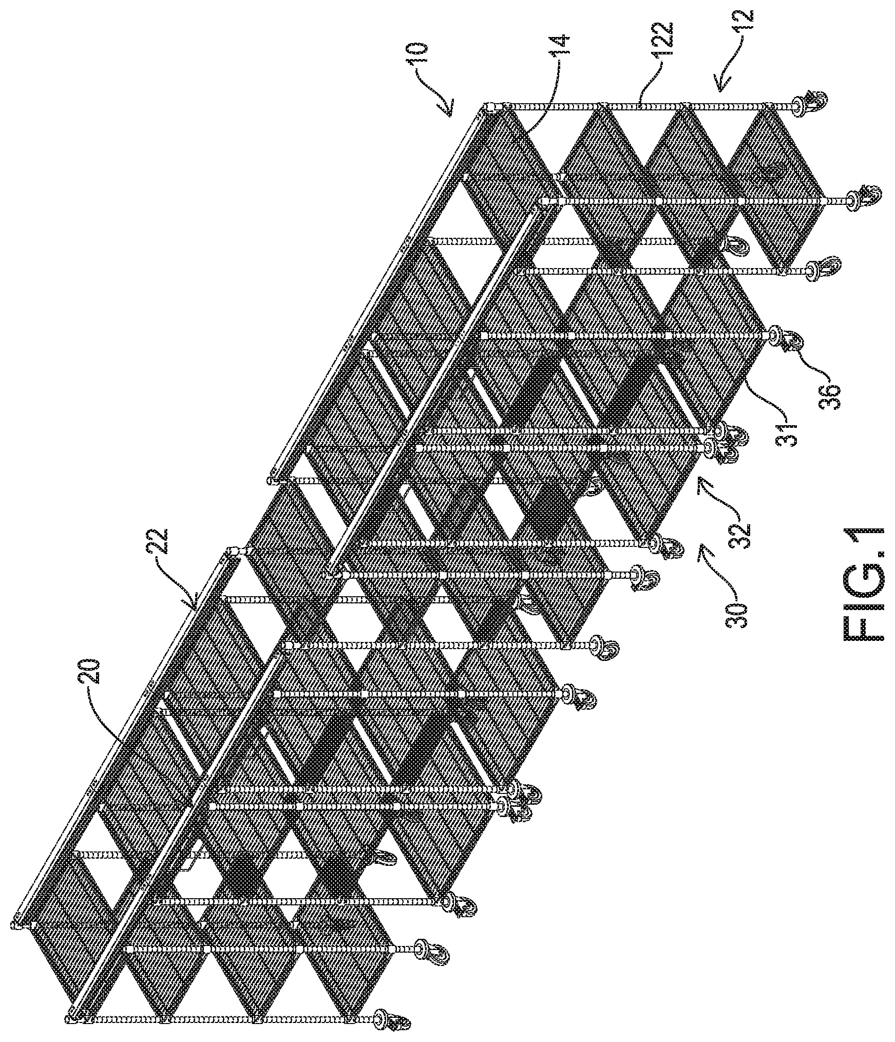
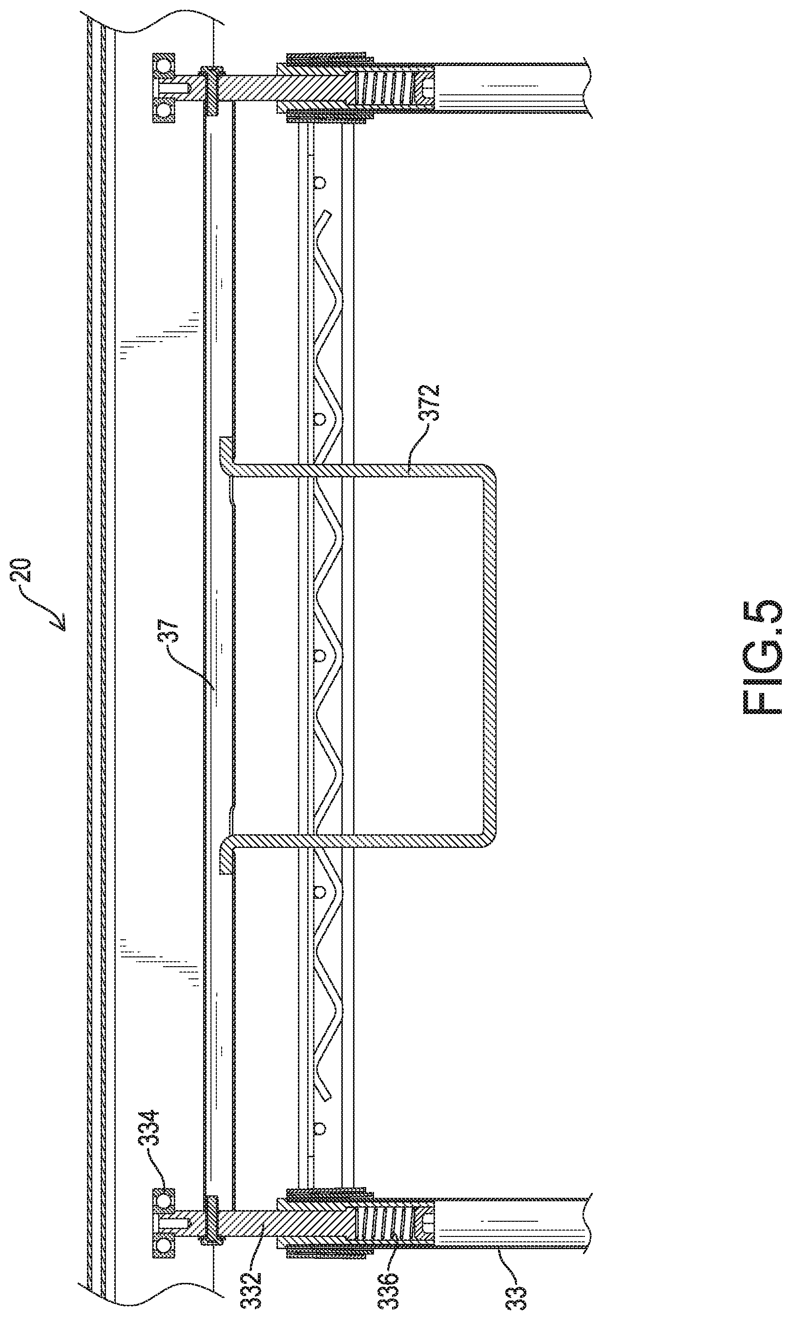
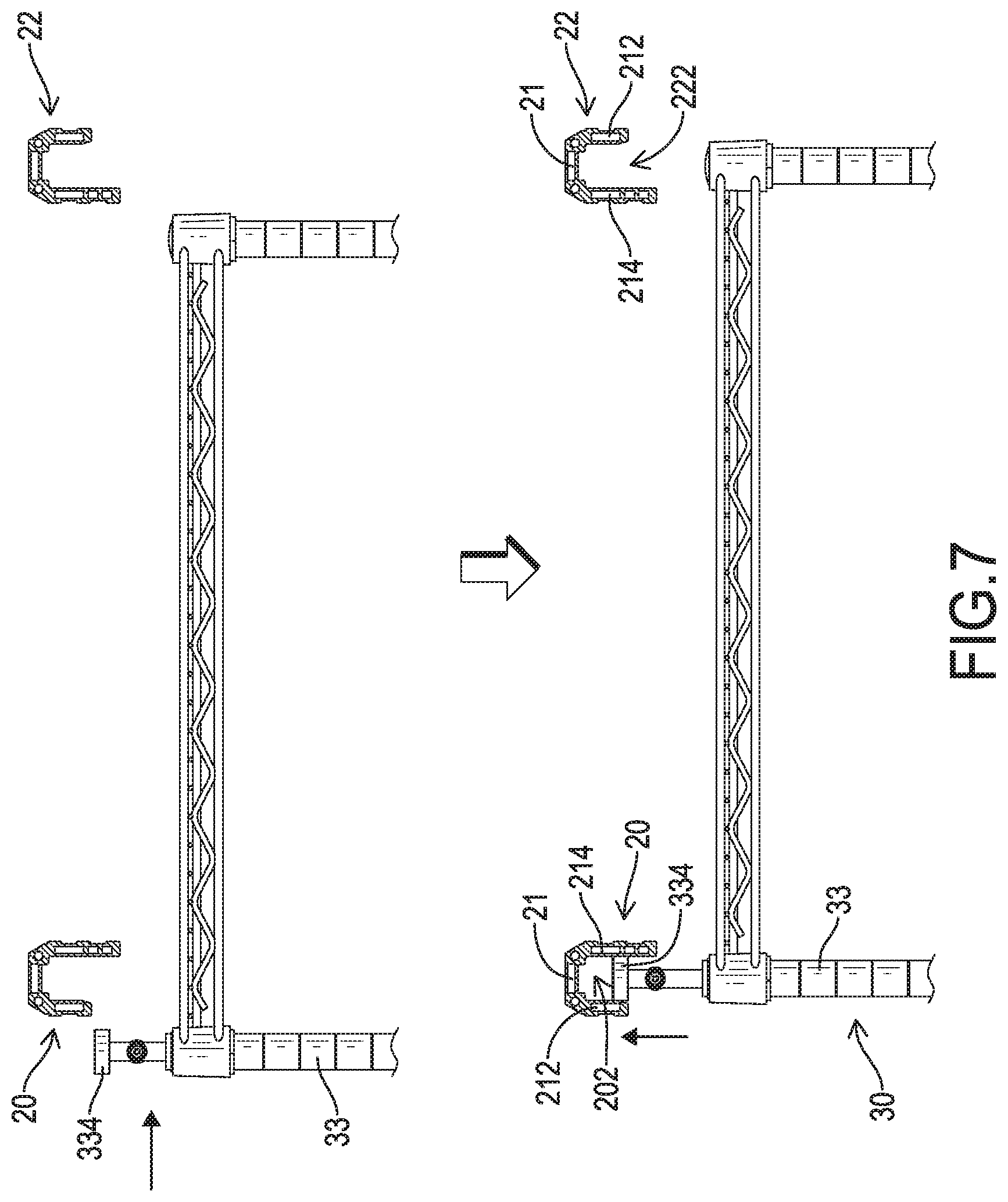
[0016] With reference to FIG. 1, a rack assembly in accordance with the present invention comprises two side racks 10, two rails 20,22 and at least one sub-rack 30. The side racks 10 are spaced from each other. Each side rack 10 comprises a rack frame 12 composed of multiple longitudinal rods 122 and at least one supporting member 14 mounted securely on the rack frame 12. Each supporting member 14 may be a plate or a bracket to support objects on the supporting member 14. The rails 20,22 are mounted between and connected with the side racks 10, are parallel with each other, are located at a same height, and include a front rail 20 and a rear rail 22.With reference further to FIG. 7, each rail 20,22 has a U-section to form an opening 202,222 in a bottom of the rail 20,22. Each rail 20, 22 comprises a bottom panel 21, an outer panel 212, and an inner panel 214. The outer panel 212 and the inner panel 214 are respectively formed on and extend downwardly from two sides of the bottom panel 21. The inner panels 214 of the two rails 20, 22 face each other. The inner panel 214 of each rail 20, 22 has a downward extension length larger than a downward extension length of the outer panel 212 of the rail 20,22.
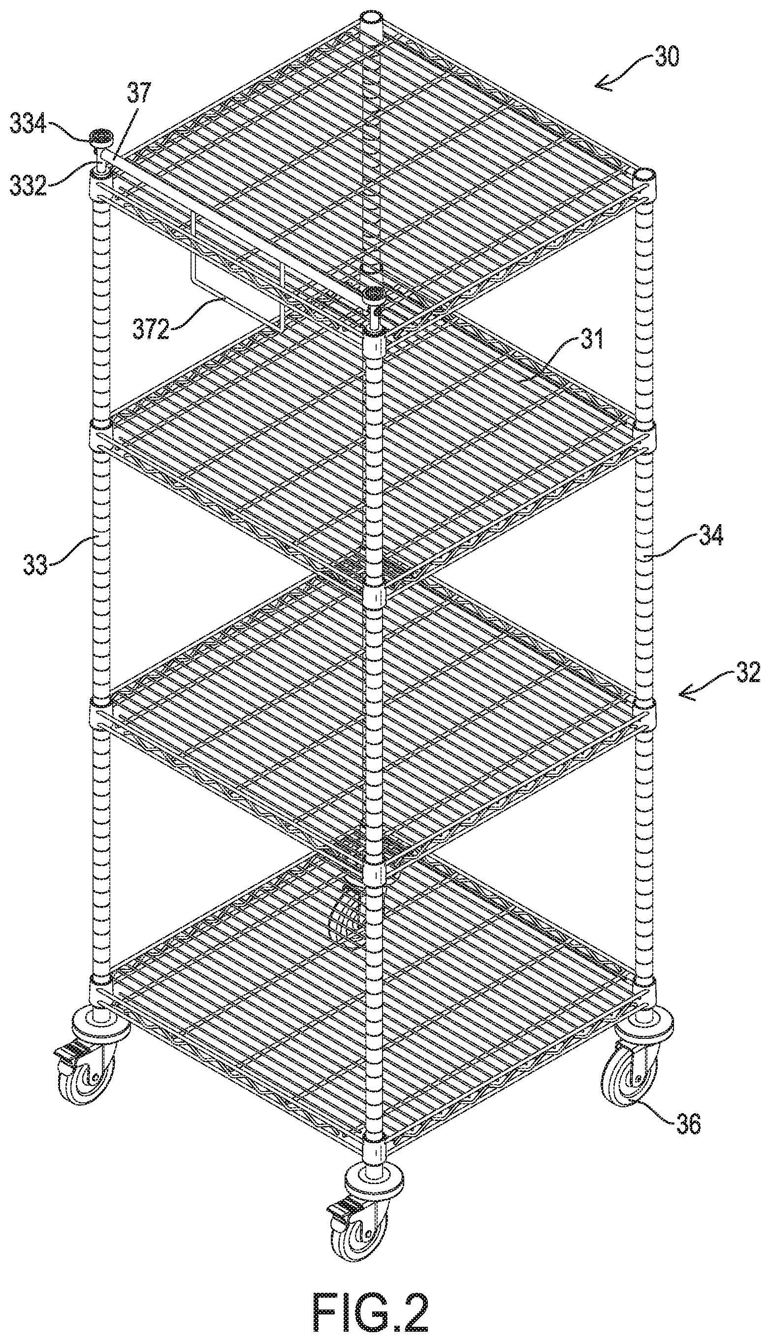
[0017] With reference to FIGS. 2 to 4, the at least one sub-rack 30 is disposed between the side racks 10 and is slidable along the rails 20,22. In the embodiment as shown in FIG. 1, two sub-racks 30 are implemented. Each sub-rack 30 comprises a rack frame 32, a connection rod 37, and at least one supporting member 31. The rack frame 32 is composed of multiple longitudinal rods 33,34. The rods 33,34 include at least one front rod 33 and at least one rear rod 34 corresponding in position respectively to the front rail 20 and the rear rail 22. Preferably, two front rods 33 and two rear rods 34 are implemented. Each front rod 33 has an extension rod 332 mounted retractably on a top of the front rod 33 and having a top and a front wheel 334 mounted rotatably on the top of the extension rod 332. Consequently, each front rod 33 has a total length larger than a total length of each rear rod 34. In addition, each front rod 33 has a spring 336 mounted in the front rod 33 and abutting a bottom of the extension rod 332 to push the extension rod 332 upward and to hold the front wheel 334 in the front rail 20. Furthermore, each rod 33,34 has a bottom and a rotating wheel 36 mounted on the bottom of the rod 33,34.
[0018] The connection rod 37 is connected to the extension rods 332 of the front rods 33. In addition, each sub-rack 30 further comprises a pulling rod 372 mounted on the connection rod 37 of the sub-rack 30. Accordingly, the connection rod 37 can be pulled downward by pulling the pulling rod 372, and the extension rods 332 can be retracted into the front rods 33 and the front wheels 334 will escape from the front rail 20 via the opening 202 in the front rail 20.
[0019] The at least one supporting member 31 is mounted securely on the rack frame 32. Each supporting member 31 may be a plate or a bracket to support objects on the supporting member 31.
[0020] With reference to FIGS. 1, 3, and 4, when in use, front wheels 334 on the front rod 33 of each sub rack 30 are held in a channel defined between the front panel 212 and the rear panel 214 of the front rail 20 and rotatably abut the inner surface of the inner panel 314 of the front rail 20. Accordingly, the sub racks 30 are moveable along the rails 20, 22, and the positions of the sub-racks 30 are adjustable. Therefore, the rack assembly in accordance with the present invention is versatile in use.
[0021] With reference to FIGS. 5 to 7, when the connection rod 37 or the pulling rod 372 of one of the sub-racks 30 is pulled downward, the extension rods 332 of said one of the sub-racks 30 will be retracted into the front rods 33 and the front wheels 334 will escape from the front rail 20 via the opening 202 of the front rail 20. Accordingly, the sub-rack 30 can be pushed to move forward relative to the side racks 10 even to leave the position between the side racks 10. Consequently, the sub-rack 30 can be applied to support objects individually. Therefore, the amounts and the positions of the sub-racks 30 between the side racks 10 can be changed to fit with different user demands, such that the rack assembly is versatile in use.
[0022] Additionally, because the rails 20, 22 are located at the same height, and the total length of the front rods 33 of each sub-rack 30 is larger than the total length of the rear rod 34 of the sub-rack 30, the sub-racks 30 can be put into a position between the side racks 10 from the front rail 20 as shown in FIG. 7. The sub-racks 30 may be put into a position between the side racks 10 from the rear rail 22 as shown in FIG. 8. Therefore, the sub-racks 30 can be combined with the side racks 10 along different directions to fit with different use demands Thus, the rack assembly in accordance with the present invention is versatile in use.
[0023] Even though numerous characteristics and advantages of the present invention have been set forth in the foregoing description, together with details of the structure and function of the invention, the disclosure is illustrative only, and changes may be made in detail, especially in matters of shape, size, and arrangement of parts within the principles of the invention to the full extent indicated by the broad general meaning of the terms in which the appended claims are expressed.
* * * * *
D00000
D00001
D00002
D00003
D00004
D00005
D00006
D00007
D00008
XML
uspto.report is an independent third-party trademark research tool that is not affiliated, endorsed, or sponsored by the United States Patent and Trademark Office (USPTO) or any other governmental organization. The information provided by uspto.report is based on publicly available data at the time of writing and is intended for informational purposes only.
While we strive to provide accurate and up-to-date information, we do not guarantee the accuracy, completeness, reliability, or suitability of the information displayed on this site. The use of this site is at your own risk. Any reliance you place on such information is therefore strictly at your own risk.
All official trademark data, including owner information, should be verified by visiting the official USPTO website at www.uspto.gov. This site is not intended to replace professional legal advice and should not be used as a substitute for consulting with a legal professional who is knowledgeable about trademark law.