Energy diverting football helmet
Baker; Michael ; et al.
U.S. patent application number 16/602597 was filed with the patent office on 2020-05-28 for energy diverting football helmet. The applicant listed for this patent is Michael Baker Baker. Invention is credited to Leonard Samuel Baker, Michael Baker.
| Application Number | 20200163398 16/602597 |
| Document ID | / |
| Family ID | 70771350 |
| Filed Date | 2020-05-28 |


View All Diagrams
| United States Patent Application | 20200163398 |
| Kind Code | A1 |
| Baker; Michael ; et al. | May 28, 2020 |
Energy diverting football helmet
Abstract
An energy diverting football helmet is disclosed. The helmet contains the shell having an inside and an outside, padding positioned against the inside of the shell. There is also a face mask attached to the front of the football helmet, and a chin strap. On the outside of the shell there is a plurality of flexible energy divergent baffles (FEDB) attached to the outside of said shell. The flexible energy divergent baffle comprises a base, a flat top, and an offset baffle connecting the flat top with the base. On top of the base is a wafer, upon which resides an energy transferring bumper.
| Inventors: | Baker; Michael; (Waldorf, MD) ; Baker; Leonard Samuel; (Scottsdale, AZ) | ||||||||||
| Applicant: |
|
||||||||||
|---|---|---|---|---|---|---|---|---|---|---|---|
| Family ID: | 70771350 | ||||||||||
| Appl. No.: | 16/602597 | ||||||||||
| Filed: | November 7, 2019 |
Related U.S. Patent Documents
| Application Number | Filing Date | Patent Number | ||
|---|---|---|---|---|
| 62917127 | Nov 23, 2018 | |||
| Current U.S. Class: | 1/1 |
| Current CPC Class: | A42B 3/062 20130101; A42B 3/069 20130101; A42B 3/064 20130101 |
| International Class: | A42B 3/06 20060101 A42B003/06 |
Claims
1) An energy diverting football helmet, said helmet comprising: a) a shell, said shell having an inside and an outside; b) padding positioned against the inside of the shell; c) a face mask attached to the front of the football helmet; d) a chin strap; and e) a plurality of flexible energy divergent baffles attached to the outside of said shell.
2) The football helmet of claim 1, wherein each said flexible energy divergent baffle comprises: a) a base; b) a flat top; and c) an offset connector system connecting the flat top with the base.
3) The football helmet of claim 2, wherein each said flexible energy divergent baffle has a duro of no greater than 45.
4) The football helmet of claim 3, wherein each said flexible energy divergent baffle has a duro no greater than 35.
5) The football helmet of claim 4, wherein each said flexible energy divergent baffle has a duro no greater than 30.
6) The football helmet of claim 4, wherein each said flexible energy divergent baffle is made of a material selected from the group consisting of rubber, plastic, or silicone.
7) The football helmet of claim 2, further comprising a wafer, said wafer affixed to said top of said flexible energy divergent baffle.
8) The football helmet of claim 7, further comprising a bumper, said bumper affixed to said wafer positioned on to of said flexible energy divergent baffle.
9) The football helmet of claim 8, wherein said bumper is comprised of a material consisting of rubber, plastic, or silicone.
10) The football helmet of claim 2, further comprising a bumper, wherein said bumper is affixed to said flexible energy divergent baffle.
11) The football helmet of claim 8, wherein said bumpers have a dur of between about 70 to about 100.
12) The football helmet of claim 10 wherein said bumper has a dur of between about 70 to about 100.
13) The football helmet of claim 9, further comprising a soft plastic layer covering the bumpers, said soft plastic layer having a dur of no greater than about 50.
Description
[0001] This application claims benefit to U.S. provisional application 62/917,127, filed Nov. 23, 2019.
[0002] A helmet is disclosed which diverts and absorbs the energy of an impact.
BRIEF DESCRIPTION OF THE DRAWINGS
[0003] FIG. 1 is a cross section of a football helmet;
[0004] FIG. 2A is a perspective of a flexible energy divergent baffle;
[0005] FIG. 2B is a side view of the flexible energy divergent baffle;
[0006] FIG. 3 is a perspective view of another embodiment of the flexible energy divergent baffle;
[0007] FIG. 4 is a perspective view of a plurality of the flexible energy divergent baffles on the football helmet;
[0008] FIG. 5 is a front view of a bumper;
[0009] FIG. 5 is a side view of a flexible energy divergent baffle with a wafer positioned on top.
[0010] FIG. 6 is a side view of a flexible energy divergent baffle with a wafer position on top and a bumper positioned on top of the wafer;
[0011] FIG. 7 is a front view of bumper assemblies covering the helmet;
[0012] FIG. 8 is the right side view of the bumper assemblies covering the helmet;
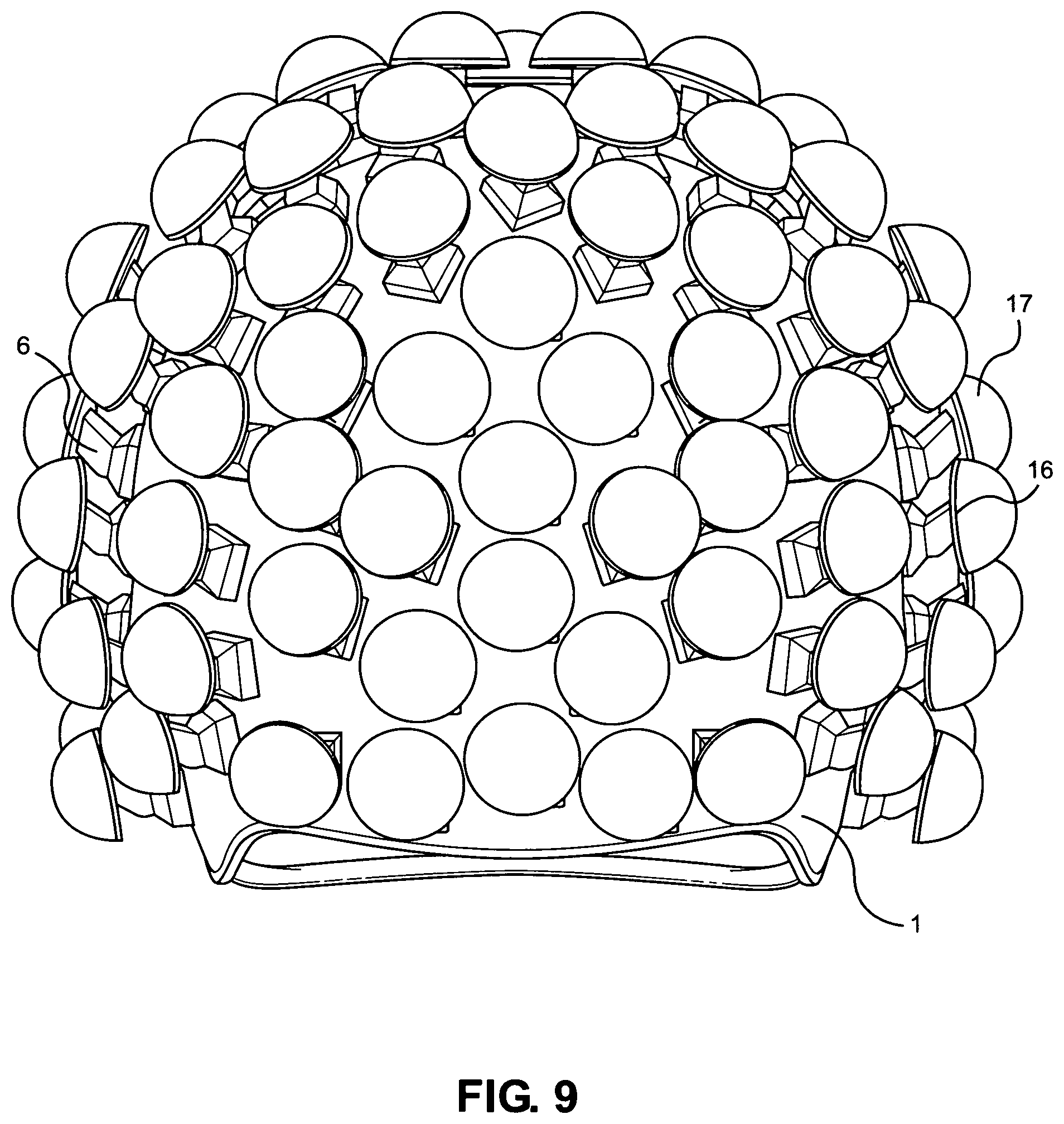
[0013] FIG. 9 is a back view of the bumper assemblies covering the helmet;
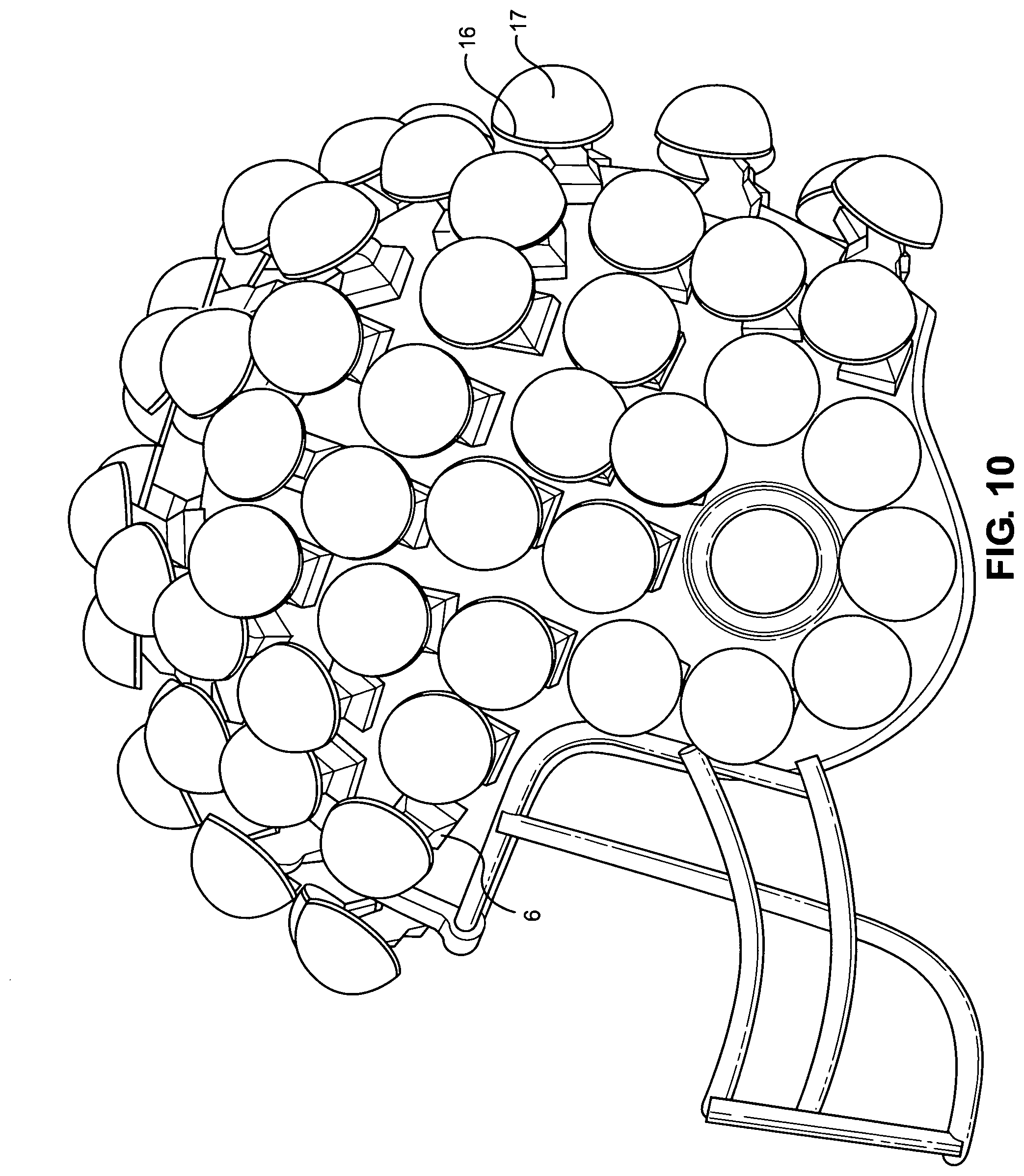
[0014] FIG. 10 is a left side view of the bumper assemblies covering the helmet;
[0015] FIG. 11 is a cross view of an outer soft covering over the bumper assemblies on the helmet;
[0016] FIG. 12 is perspective view of a helmet cover removed from one side;
[0017] FIG. 13A is a side view showing the head position and orientation for impact site F;
[0018] FIG. 13B is an overhead view showing the head position and orientation for impact site F;
[0019] FIG. 14A is a side view showing the head position and orientation for impact site C;
[0020] FIG. 14B is an overhead view showing the head position and orientation for impact site C;
[0021] FIG. 15A is a side view showing the head position and orientation for impact site D;
[0022] FIG. 15B is an overhead view showing the head position and orientation for impact site D;
[0023] FIG. 16A is a side view showing the head position and orientation for impact site R;
[0024] FIG. 16B is an overhead view showing the head position and orientation for impact site R;
[0025] FIG. 17A is a side view showing the head position and orientation for impact site A;
[0026] FIG. 17B is an overhead view showing the head position and orientation for impact site A;
[0027] FIG. 18A is a side view showing the head position and orientation for impact site A';
[0028] FIG. 19A is a side view showing the head position and orientation for impact site B;
[0029] FIG. 19B is an overhead view showing the head position and orientation for impact site B;
[0030] FIG. 20A is a side view showing the head position and orientation for impact site UT;
[0031] FIG. 20B is an overhead view showing the head position and orientation for impact site UT;
[0032] FIG. 21A-21C graphs the acceleration vs Serverity Index versus the HIC 15.
[0033] FIG. 22 is a chart showing the comparisons of the protection offered by the helmets taught in the disclosure compared to a standard helmet under ambient conditioned impacts;
[0034] FIG. 23 is a chart showing the comparisons of the protection offered by the helmets taught in the disclosure compared to a standard helmet under hot conditioned impacts;
[0035] FIG. 24 is a chart showing the results of linear acceleration testing of the helmets;
[0036] FIG. 25 is a chart showing the results of HIC15 testing of the helmets; and
[0037] FIG. 26 is a chart showing the results of Severity Index testing of the helmets.
[0038] The figures depict various embodiments of the described methods and kit and are for purposes of illustration only. One skilled in the art will readily recognize from the following discussion that alternative embodiments of the methods and kits illustrated herein may be employed without departing from the principles of the methods and kits described herein.
DETAILED DESCRIPTION OF THE EMBODIMENT
[0039] The football helmet 1 disclosed herein is designed to better protect the wearer from a head injury. More specifically, the football helmet 1 is designed to reduce the risk of head and brain injuries during the playing of the game. The embodiments taught can be used for other helmets, including safety (construction) helmets.
[0040] The typical football helmet 1 is made of a hard plastic. More specifically, the football helmet is a hard shell 2 with thick padding 3 on the inside and underneath the hard shell 2, a face mask 4 made of one or more plastic-coated metal bars, and a chinstrap 5 The plastic shell 2 is normally made out of polycarbonate and can have a duro rating greater than about 100.
[0041] In one embodiment of the present disclosure, a plurality of flexible energy divergent baffles (FEDBs) 6 are attached to the outer surface 21 of the shell 2 of the helmet 1. The energy divergent baffles 6 each comprise a base 7, a foot or support 9, and an off center flat top 10 positioned and integral with said foot or support 9. In one embodiment, a rectangular or square base 7 is positioned on top of an upturned pentagonal foot 9 which is positioned on top of a flat topped pyramidal platform 8 positioned on top and integral with the square base 7, with the off center flat top 10 extending beyond one of the perimeter walls 11, 12, 13, 14 of the base. In another embodiment, the base 7 is not square or rectangular, but any shape that gives the FEDB 6 enough balance. Similarly, the flat top can be of any shape as long as it is flat.
[0042] The height of the FEDB 6 can range from about a 1/4'' high to about 1'' high. These ranges are not limited and the FEDB 6 can be larger or smaller than indicated. To give some perspective, the 1'' high FED 6 has a base measuring about 1'' by about 1'' and the flat top is about 7/8'' long and about 1/2'' wide. It should be noted that the base of the FEDB 6 can range up to about 2'' or more, if so desired, and the flat top can be proportionately larger as well. These numbers may also vary. The FEDB 6 have a duro value in one embodiment of no greater than about 35 to about 40. The duro can be as lower or lower than about 30. In yet another embodiment, the duro can be between about 40 to about 50. In one embodiment, the FEDB 6 are made out of a flexible rubber such that they can angularly bend when an item strikes them. In another embodiment, the FEDB 6 is made out of plastic or silicone or any other material that allows for the traits described therein. It should also be noted that the material used should have memory.
[0043] In another embodiment, the FEDB can be in the general shape of a "Z" 20. The base 29 of the "Z" 20 is attached to the outer surface 21 of the shell 2 of the helmet 1. A thickened diagonal section 22 supports a flat top 23. In yet another embodiment, the FEDB can be in the shape of a staple 24. The staple shaped FEDB 24 has a base 25, a vertical support 26, and a flat top 27. For clarity purposes, the proximal end of the of the vertical support 26 is positioned at one end of the base, and the distal end of the vertical support 26 is attached to the flat top 27. The parts of the FEDB are integrally attached, and in one embodiment are molded in one piece.
[0044] Fundamentally, in another embodiment, the FEDB can be of any shape, as long as the flat top is off center from a vertical support 26.
[0045] The FEDB 6 is secured to the outside of the football shell 2. Any method can be used to secure the FEDB 6 to the outside of the football shell 2, including the use of rubber cement, rubber paint, and mixtures thereof, as well as other types of glues. There may also be other means of attachment known in the art, including small screws. In one embodiment, the FEDB 6 cover the entire outer surface of the shell 2. When the FEDB are about one inch tall, it takes about 70 FEDBs to cover the entire outer surface of the shell 2.
[0046] It should be noted that the FEDB 6 can be solid, or it can be hollow. A hollow FEDB 6 will lighten the weight of the helmet.
[0047] On the top of the off-center/offset flat top 10 of each of the FEDB 6 is rigid flat wafer 16. In one embodiment, the wafer 16 is made out of carbonate, of which football helmets are usually made In other embodiments, the wafer 16 is made out of aluminum, a steel alloy, any metals or metal alloys stronger or lighter than steel, and any plastics stronger and lighter than steel. The wafer can also be made out of Kevlar. Depending on the material used, the width of the wafer 16 can range from about 1/16'' to about 1/4''. In one embodiment, the wafer has the same outer dimensions as the perimeter of the flat top 10. In another embodiment, the wafer 16 extends beyond the perimeter of the flat top 10. The amount of overlap of the wafer 16 on the flat top 10 may vary.
[0048] On top of the wafer 16 is attached a bumper 17. In one embodiment, the wafer 16 is first attached to the bumper 17 before being attached to the flat top 10 of the FEDB 6. In another embodiment, the wafer is first attached to the to the flat top 10 before the bumper 17 is attached. In yet another embodiment, everything is assembled before the FEDB 6 is attached to the shell.
[0049] The bumper 17 has a duro hardness ranging from about 70 to about 100 duro. The bumper 17 is in the shape of a semicircle or more correctly, is in the shape of half of a hollow ball, and is made out of either rubber or plastic. While the phrase "half a hollow ball" is used, the shape is somewhat more or less than half a hollow ball, such that there can be a ball that was cut on about the 30% mark to about the 60% mark. The outside width of the bumper can range in size from 1'' to about 2'' with some sizes smaller or larger. In one embodiment, the outside width of the bumper is about 1.5 inches. In another embodiment, the outside width of the bumper is two inches. Where the outside width of the of the bumper is at least 1'' to about 2'', the width 28 of the rubber or plastic is about 1/4''. The bumper 17 is attached to the wafer 16 by any effective means known in the art, including rubber glue or any other effective glue. In one embodiment, the bumper 17 is larger than the wafer 16, and yet in another embodiment, the bumper 17 is smaller than the wafer 16. Given that the bumper 17 is round, some parts of the bumper may extend beyond the wafer 16. In another embodiment, the shape and width of the base 36 is about equivalent to the width and shape of the wafer 161t should also be noted that the duro hardness of the bumper 17 may fall outside of the range given, and may be softer or harder than indicated.
[0050] The bumpers 17, and the FEDBs 6 can be made out of rubber, plastic, or other materials that have elasticity. The wafer 16 can be made out of rubber, plastic, metal or other materials.
[0051] In yet another embodiment, the bumper 17 resides directly on top of the FED 6, without the need of a wafer 16 interface.
[0052] In football, when a player is hit in the head, the impact can be in excess of 150g forces. When the wearer of the present helmet is hit in the head, instead of the energy being directly transmitted to the player's head, thereby risking a concussion, the bumpers 17 absorb and transfer the energy angularly away from the point of impact. The FEDBs 6 further absorb and transfer the energy angularly away from the point of impact. This lessens the risk of concussion as the inertia energy is dispersed and distributed away from the point of impact. Much of the energy is spent by the movement of the bumper and the FEDB 6, while much of the impact energy is distributed over the entire helmet.
[0053] Other embodiments can further lessen the effects of an impact. In embodiment, the shell 2 of the football helmet 1 is made of a material giving the shell a hardness rating less than about 100. In another embodiment, this shell 2 could be soft enough so as to indent upon impact. In one embodiment, this soft shell 2 is made of a soft plastic or a rubber having a duro at or under about 80 duros, and in one embodiment in about the 70 to about 80 duro range. In yet another embodiment, the duro range of the shell 2 can be in the about 30 to about 80 range, and in yet another embodiment the shell 2 has a range of from about 30 to about 50. In yet n another embodiment, only selected parts of the shell 2 have a selected duro in the range of about 30-50, in order to reduce impact-force transfer to the athlete's head. In another embodiment, flex is engineered into the helmet's shell, facemask, and attachment system.
[0054] In one of the embodiments, the largest section of helmet padding is stiff polypropylene foam that nearly covers the entire internal surface of the helmet. Its main role is to absorb impacts and provide general protection. In another embodiment, the helmet padding is a gel pad. In another embodiment, the helmet pad is is water filled pad. This further allows for energy absorption from an impact. In another embodiment EVA foam, a closed cell foam made from ethylene Vinyl Acetate and blended co-polymers is used for the inner pad.
[0055] In yet another embodiment, the seat of the chin strap, or the part where the chin fits, has a gel cushion insert.
[0056] In yet another embodiment, there is a soft plastic outer layer 30 covering the semi-circular bumpers 17. This soft plastic outer layer 30, having a dur value of about 30 to about 50, will provide additional protection both for the wearer of the helmet and for any opposing player. In yet another embodiment, the soft plastic outer covering has the same appearance as the shell 2, and is unrippled on the outside surface 33 of the shell. There are a number of ways known in the art to attach the outer covering. In one embodiment, FIG. 12 shows one embodiment in which the plastic cover 30, only partially covering the bumpers 17, have hooks 40 which attach to the helmet between the hard shell 2 and the thick padding 3. In another embodiment, a hook and loop arrangement is used. In other embodiments, other means of attachment, including loops, can be used.
Testing
[0057] Several different impact sites on the helmet proposed by this disclosure and compared to football helmets currently being sold in the market place. The tests were performed by corner Chesapeake Testing, a NTS company, which is itself is an accredited independent helmet testing company. The actual tests performed correspond to the standards and tests agreed upon by the NFLPA (The NFL Players Association).
[0058] Three football helmets were tested, with two of the helmets being those taught in the disclosure. One of the proposed helmets tested has a bumper having a diameter of 1.5 inches, and the other proposed helmets has a diameter of 2'' The other helmet is a commonly sold helmet.
[0059] There are four terms used in the charts.
[0060] The Severity Index (SI) is a threshold value for a general category of head injuries based on scientific research and published data. SI is a method for measuring a helmet's ability to reduce impact forces to the head, integrating acceleration over time. SI provides an accurate way to assess head injury risk that can be replicated across laboratories and under different impact scenarios. The NOCSAE standards are performance based and are design neutral so that manufacturers are not restricted in design or engineering, allowing innovation in design.
[0061] Linear Acceleration is the acceleration of the head in the direction of the impact. This is recorded in G's which is an acceleration value related to free-fall acceleration.
[0062] Average Acceleration is the maximum linear acceleration experienced at the center of gravity (center) of the head.
[0063] HIC 15 is a unit-less value that is closely related to SI, capturing the most aggressive 15-milliseconds of the impact event. The Acceleration vs. SI vs. HIC graph is shown in FIGS. 21A-21C. The ambient conditioned impacts testing results are found in FIG. 22, the Hot Conditioned Impact results are found in FIG. 23. FIGS. 24, 25, and 26 show the Linear Acceleration test results, the HIC15 test results, and the Severity Index test results. The codes in the Impact Site column correspond to the impact on the helmets shown in FIGS. 13 through 20. The Baker helmets correspond to the helmets in the disclosure and the tests are using the 1.5 and 2.0 inch bumpers for the Baker helmets.
[0064] As the charts show, the Baker helmets cushion is a great improvement over the standard football helmet. blows from those one could expect in a football game. Such an improvement will greatly reduce head injuries when playing football.
[0065] It should be noted that the embodiments described herein can be used in combination with each other or with other embodiments. Additionally, the safety features described herein may be used with other helmets other than a football helmet. The safety features could be used in construction helmets, for example.
[0066] While various embodiments of the present disclosure have been described above, it should be understood that they have been presented by way of example only, and not limitation. It will be apparent to persons skilled in the relevant art that various changes in form and detail can be made therein without departing from the spirit and scope of the disclosure. Thus, the breadth and scope of the present disclosure should not be limited by any of the above-described exemplary embodiments, but should be defined only in accordance with the following claims and their equivalents.
* * * * *
D00000
D00001
D00002
D00003
D00004
D00005
D00006
D00007
D00008
D00009
D00010
D00011
D00012

D00013

D00014

D00015

D00016

D00017

D00018

D00019

D00020

D00021

D00022

D00023

XML
uspto.report is an independent third-party trademark research tool that is not affiliated, endorsed, or sponsored by the United States Patent and Trademark Office (USPTO) or any other governmental organization. The information provided by uspto.report is based on publicly available data at the time of writing and is intended for informational purposes only.
While we strive to provide accurate and up-to-date information, we do not guarantee the accuracy, completeness, reliability, or suitability of the information displayed on this site. The use of this site is at your own risk. Any reliance you place on such information is therefore strictly at your own risk.
All official trademark data, including owner information, should be verified by visiting the official USPTO website at www.uspto.gov. This site is not intended to replace professional legal advice and should not be used as a substitute for consulting with a legal professional who is knowledgeable about trademark law.