Dual Heating Chamber Vaporization Device
Trzecieski; Michael
U.S. patent application number 16/692999 was filed with the patent office on 2020-05-28 for dual heating chamber vaporization device. The applicant listed for this patent is Michael Trzecieski. Invention is credited to Michael Trzecieski.
| Application Number | 20200163382 16/692999 |
| Document ID | / |
| Family ID | 70771340 |
| Filed Date | 2020-05-28 |


View All Diagrams
| United States Patent Application | 20200163382 |
| Kind Code | A1 |
| Trzecieski; Michael | May 28, 2020 |
Dual Heating Chamber Vaporization Device
Abstract
A dual heating chamber vaporization device is disclosed having a device body with at least an air inlet and a heating unit. The heating unit includes a first heating chamber for accommodating a first material for vaporization the material for generating a first aerosol when subjected to a first heat from a first heating element assembly and for generating a second aerosol when subjected to a second heat from a second heating element assembly and for generating at least one of a first and second aerosol as a first vapor. A second heating chamber is included with a second heating element assembly for heating a second material for vaporization doe generating a second aerosol when subjected to second heat. A detachable mouthpiece lid is for receiving of the at least one of the first and second vapor for providing this vapor to a user through an inhalation aperture.
| Inventors: | Trzecieski; Michael; (Toronto, CA) | ||||||||||
| Applicant: |
|
||||||||||
|---|---|---|---|---|---|---|---|---|---|---|---|
| Family ID: | 70771340 | ||||||||||
| Appl. No.: | 16/692999 | ||||||||||
| Filed: | November 22, 2019 |
Related U.S. Patent Documents
| Application Number | Filing Date | Patent Number | ||
|---|---|---|---|---|
| 62770987 | Nov 23, 2018 | |||
| 62845328 | May 9, 2019 | |||
| Current U.S. Class: | 1/1 |
| Current CPC Class: | A24F 40/50 20200101; A24F 40/46 20200101; A24F 40/57 20200101; A24F 40/30 20200101 |
| International Class: | A24F 40/46 20060101 A24F040/46 |
Claims
1. A dual heating chamber vaporization device comprising: a device body comprising a heating unit, the heating unit comprising: a first heating chamber having a first end and a second end opposite the first end and one or more first chamber sidewalls extending from the first end to the second end with a first chamber third sidewall capping the first heating chamber proximate the second end, the one or more first chamber sidewalls together with the first chamber third sidewall defining a first chamber cavity having a first open end proximate the first end and the first chamber third sidewall comprising first chamber pores 106p, where air flows into the first chamber cavity through the first chamber pores and where phyto material may be loaded into the first chamber cavity through this first open end; a first heating element assembly for heating the phyto material within the first chamber cavity through a conduction heating process; a second heating chamber having a first end and a second end opposite the first end and one or more second chamber sidewalls extending from the first end to the second end with a second chamber third sidewall capping the second heating chamber proximate the second end, the one or more second chamber sidewalls together with the second chamber third sidewall defining a second chamber cavity having a second open end proximate the first end and the second chamber third sidewall comprising second chamber pores 206p, where air flows into the second chamber cavity through the second chamber pores and phyto material extracts may be loaded into the second chamber cavity through this second open end; NB This is for bottom flow and we need to have side flow a second heating element assembly for heating phyto material extract within the second chamber cavity through a conduction heating process; a heating unit airflow path that extends from an air inlet to the first and second chamber cavities via the first and second chamber pores; a control circuit electrically coupled to the first and second heating element assemblies; an energy storage module electrically coupled to the control circuit; and, a mouthpiece lid movably mounted to the device body, the mouthpiece lid movable between an open position and a closed position, the mouthpiece lid comprising: an outer wall; a lid floor having a perforated floor section and; an inner lid space defined between the outer wall and the lid floor; an inhalation aperture defined in the outer wall, the inhalation aperture fluidly coupled to the inner lid space and downstream from the lid floor, in the open position, the chamber cavity is open to the external environment and the phyto material is loadable within one of the first and second chamber cavities, in the closed position, the lid and the first and second heating chambers enclose the first and second chamber cavities, and at least a portion of the perforated floor section overlies the first and second chamber cavities proximate the first ends, whereby the first and second chamber cavities and the inner lid space are fluidly connected; where in the closed position, at least one of the first and second heating element assemblies are energizable to heat phyto material disposed within the chamber cavities to a predetermined first and second vaporization temperatures for creating a first vapor and a second vapor; and to define a vapor flow path from the first and second chamber cavities through the perforated floor to the inner lid space and the inhalation aperture for the first vapor and second vapor to propagate through the inhalation aperture and wherein the second heating element assembly is for operating at a higher temperature than the first heating element assembly.
2. A dual heating chamber vaporization device according to claim 1 comprising: an air cooling assembly positioned within the inner lid space at least partially overlying the perforated floor section, the air cooling assembly for receiving of the first vapor and second vapor and for mixing the first and second vapor prior to having mixed vapor to propagate through the inhalation aperture.
3. A dual heating chamber vaporization device according to claim 1 comprising: a separator rib disposed between first open end and the second open end of the first and second heating chamber cavities the separator rib for extending outwards from the device body towards the mouthpiece lid which comprises a separator rib cavity for receiving of the separator rib when the mouthpiece lid is in the closed position.
4. A dual heating chamber vaporization device according to claim 1 wherein the lid floor having a perforated floor section comprises a first perforated floor section and a second perforated floor section, wherein the in the closed position, the lid and the first perforated floor section and the second perforated floor section enclose the first and second chamber cavity, and at least a portion of the first perforated floor section overlies the first chamber cavity and at least a portion of the second perforated floor section overlies the second chamber cavity where the first and second chamber cavities and the inner lid space are fluidly connected through the first and second perforated floor sections.
5. A dual heating chamber vaporization device according to claim 1 wherein the lid floor having a perforated floor section comprises a first perforated floor section and a second perforated floor section, wherein the in the closed position, the lid and the second perforated floor section and the first perforated floor section enclose the first and second chamber cavity, and at least a portion of the second perforated floor section overlies the first chamber cavity and at least a portion of the first perforated floor section overlies the second chamber cavity where the first and second chamber cavities and the inner lid space are fluidly connected through the second and first perforated floor sections.
6. A dual heating chamber vaporization device according to claim 2 wherein: the lid floor having a perforated floor section comprises a first perforated floor section and a second perforated floor section, wherein the in the closed position, the lid and the first perforated floor section and the second perforated floor section enclose the first and second chamber cavity, and at least a portion of the first perforated floor section overlies the first chamber cavity and at least a portion of the second perforated floor section overlies the second chamber cavity where the first and second chamber cavities and the inner lid space are fluidly connected through the first and second perforated floor sections comprising a first air cooling path length formed between the first perforated floor section and the inhalation aperture is shorter than a second air cooling path length formed between the second perforated floor section and the inhalation aperture.
7. A dual heating chamber vaporization device according to claim 1 wherein the heating unit airflow path comprises a first airpath and a second air path, the first and second airpaths extending from the air inlet to the first and second chamber cavities respectively via the first and second chamber pores wherein the first and second airpaths are substantially parallel and, in the closed position, the lid and the first and second heating chambers enclose the first and second chamber cavity where the first and second airpaths and the inner lid space are fluidly connected.
8. A dual heating chamber vaporization device according to claim 1 comprising: a first airpath and a second airpaths both meet at the inner lid space when the mouthpiece lid is in the closed position; a first ambient air input port for allowing of air to flow along the first airpath for propagating through the first heating chamber; a second ambient air input port disposed proximate the first end of the second heating chamber proximate the first end for skimming second vapor proximate the first end that are emitted by the second heating unit when heating of the phyto material extract.
9. A dual heating chamber vaporization device according to claim 8, wherein the second ambient air input port include a selectable airflow restrictor where the selectable airflow restrictor 399 is controllably movable into various positions to approximately restrict incoming ambient airflow into the second airpath 268 and to allow airflow into the second airpath in dependence upon a position thereof.
10. A dual heating chamber vaporization device according to claim 1 comprising: a thermal radiator include a third heating element assembly electrically coupled with the control circuit, the thermal radiator disposed upstream of first heating chamber and proximate the first chamber third sidewall, where the thermal radiator is substantially disposed for other than being conductively coupled with the first chamber third sidewall and for heating air propagating along a first airpath that extends from the air inlet to the first chamber cavity and the respectively via the first chamber pores, where this air is convectively heated by the thermal radiator prior to entering the first heating chamber through first chamber pores, the thermal radiator for substantially convectively heating the phyto material in addition to the first heating element assembly for heating the phyto material within the first chamber cavity through the conduction heating process wherein a thermal inertia of the thermal radiator is such that it heats up at a faster rate than the first heating element assembly.
11. A dual heating chamber vaporization device comprising: a device body comprising an air inlet and a heating unit, the heating unit comprising: a first heating chamber having a first end and a second end opposite the first end and one or more first chamber sidewalls extending from the first end to the second end with a first chamber third sidewall capping the first heating chamber proximate the second end, the one or more first chamber sidewalls together with the first chamber third sidewall defining a first chamber cavity having a first open end proximate the first end and the first chamber third sidewall comprising first chamber pores 106p, where air flows into the first chamber cavity through the first chamber pores and where phyto material may be loaded into the first chamber cavity through this first open end; a first heating element assembly for heating the phyto material within the first chamber cavity through a conduction heating process; a third heating element assembly electrically coupled with the control circuit and thermally coupled with a thermal radiator, the thermal radiator disposed upstream of first heating chamber and proximate the first chamber third sidewall, where the thermal radiator is substantially disposed for other than being conductively coupled with the first chamber third sidewall and for heating air propagating along a first airpath that extends from the air inlet to the first chamber cavity and the respectively via the first chamber pores, where this air is convectively heated by the thermal radiator prior to entering the first heating chamber through first chamber pores, the thermal radiator for substantially convectively heating the phyto material in addition to the first heating element assembly for heating the phyto material within the first chamber cavity through the conduction heating process, a second heating chamber having a first end and a second end opposite the first end and one or more second chamber sidewalls extending from the first end to the second end with a second chamber third sidewall capping the second heating chamber proximate the second end, the one or more second chamber sidewalls together with the second chamber third sidewall defining a second chamber cavity having a second open end proximate the first end and the second chamber third sidewall comprising second chamber pores 206p, where air flows into the second chamber cavity through the second chamber pores and phyto material extracts may be loaded into the second chamber cavity through this second open end; NB This is for bottom flow and we need to have side flow a second heating element assembly for heating phyto material extract within the second chamber cavity through a conduction heating process; a heating unit airflow path that extends from the air inlet to the first and second chamber cavities via the first and second chamber pores; a control circuit electrically coupled to the first and second heating element assemblies; an energy storage module electrically coupled to the control circuit; and a mouthpiece lid movably mounted to the device body, the mouthpiece lid movable between an open position and a closed position, the mouthpiece lid comprising: an outer wall; a lid floor having a perforated floor section and; an inner lid space defined between the outer wall and the lid floor; an inhalation aperture defined in the outer wall, the inhalation aperture fluidly coupled to the inner lid space and downstream from the lid floor; in the open position, the chamber cavity is open to the external environment and the phyto material is loadable within one of the first and second chamber cavities; in the closed position, the lid and the first and second heating chambers enclose the first and second chamber cavities, and at least a portion of the perforated floor section overlies the first and second chamber cavities proximate the first ends, whereby the first and second chamber cavities and the inner lid space are fluidly connected; in the closed position, at least one of the first and second heating element assemblies are energizable to heat phyto material disposed within the chamber cavities to a predetermined first and second vaporization temperatures for creating a first vapor and a second vapor; and to define a vapor flow path from the first and second chamber cavities through the perforated floor to the inner lid space and the inhalation aperture for the first vapor and second vapor to propagate through the inhalation aperture and wherein the second heating element assembly is for operating at a higher temperature than the first heating element assembly wherein the third heating element assembly is separately engageable from the first heating element assembly by the control circuit.
12. A dual heating chamber vaporization device comprising: a device body comprising at least an air inlet and a heating unit, the heating unit comprising: a detachable mouthpiece lid having an outer wall and a floor with a perforated floor section, an inner lid space and an inner lid space defined between the outer wall and the lid floor; an inhalation aperture defined in the outer wall, the inhalation aperture fluidly coupled to the inner lid space and downstream from the lid floor; a first heating chamber for accommodating comprising a first heating element assembly in thermal conduction coupling with the heating chamber for applying a source of a first heat through a thermal conduction process to the first material for vaporization for generating a first aerosol; a second heating chamber coupled with the at least an air inlet for accommodating a second material for vaporization and comprising a second heating element assembly disposed within the second heating chamber for applying a source of the second heat through a thermal conduction process to the second material for vaporization for generating a second aerosol when subjected to a second heat; a thermal radiator comprising a third heating element in thermal conduction with the thermal radiator for providing a source of third heat; the thermal radiator is in a thermally convective coupling with the first heating chamber comprising at least one airflow channel, the thermal radiator for generating for generating a hot airflow originating at the least an air inlet as the third heat when the third heating element is heated for generating a third aerosol, where the first material for vaporization is subjected to at least one of the third heat and the first heat from the first and third heating element assembly, the first heating chamber comprising an airflow passages and a porous floor for allowing the third heat to pass through the heating chamber and the material for vaporization disposed therein, at least one of the first aerosol generated and second aerosol generated and third aerosol generated for being inhaled from the inhalation aperture when the mouthpiece is coupled with the device body.
Description
CROSS-REFERENCE TO RELATED APPLICATIONS
[0001] This application claims the benefit of U.S. Provisional Application No. 62/770,987 filed Nov. 23, 2018, the entirety of which is incorporated herein by reference, and U.S. Provisional Application No. 62/845,328 filed on May 9, 2019, the entirety of which is incorporated herein by reference.
FIELD OF THE INVENTION
[0002] This application relates generally to vaporization of phyto materials, and more specifically to devices for vaporizing phyto materials.
INTRODUCTION
[0003] The following is intended to introduce the reader to the detailed description that follows and not to define or limit the claimed subject matter.
[0004] Aromatherapy generally uses plant matter, phyto materials, and essential oils, phyto material extracts, for therapeutic benefits. Essential oils can be extracted from phyto materials, such as the leaves of plants. In some cases, essential oils may be massaged into the skin to provide therapeutic benefits. In other cases, essential oils may be ingested or inhaled for therapeutic purposes.
[0005] In some cases, phyto materials may be heated in order to release the essential oils or aerosols therefrom. By heating phyto materials at predetermined temperatures, essential oils and extracts can be boiled off. Depending on the temperature at which the phyto materials are heated, an aroma or vapor may be given off. This vapor may be inhaled by a user for its
[0006] therapeutic benefits.
[0007] Various methods of vaporizing phyto materials are known. Devices that vaporize phyto materials are generally known as vaporizers and may heat through conduction, direct contact with phyto material, or may heat through convection, hot air or combinations of both.
SUMMARY
[0008] The following introduction is provided to introduce the reader to the more detailed description to follow and not to limit or define any claimed or as yet unclaimed invention. One or more inventions may reside in any combination or sub-combination of the elements or process steps disclosed in any part of this document including its claims and figures.
[0009] In accordance with an aspect of this disclosure, there is provided a dual heating chamber vaporization device comprising: a device body comprising a heating unit, the heating unit comprising: a first heating chamber having a first end and a second end opposite the first end and one or more first chamber sidewalls extending from the first end to the second end with a first chamber third sidewall capping the first heating chamber proximate the second end, the one or more first chamber sidewalls together with the first chamber third sidewall defining a first chamber cavity having a first open end proximate the first end and the first chamber third sidewall comprising first chamber pores 106p, where air flows into the first chamber cavity through the first chamber pores and where phyto material may be loaded into the first chamber cavity through this first open end; a first heating element assembly for heating the phyto material within the first chamber cavity through a conduction heating process; a second heating chamber having a first end and a second end opposite the first end and one or more second chamber sidewalls extending from the first end to the second end with a second chamber third sidewall capping the second heating chamber proximate the second end, the one or more second chamber sidewalls together with the second chamber third sidewall defining a second chamber cavity having a second open end proximate the first end and the second chamber third sidewall comprising second chamber pores 206p, where air flows into the second chamber cavity through the second chamber pores and phyto material extracts may be loaded into the second chamber cavity through this second open end; NB This is for bottom flow and we need to have side flow, a second heating element assembly for heating phyto material extract within the second chamber cavity through a conduction heating process; a heating unit airflow path that extends from an air inlet to the first and second chamber cavities via the first and second chamber pores; a control circuit electrically coupled to the first and second heating element assemblies; an energy storage module electrically coupled to the control circuit; and, a mouthpiece lid movably mounted to the device body, the mouthpiece lid movable between an open position and a closed position, the mouthpiece lid comprising:
[0010] an outer wall; a lid floor having a perforated floor section and; an inner lid space defined between the outer wall and the lid floor; an inhalation aperture defined in the outer wall, the inhalation aperture fluidly coupled to the inner lid space and downstream from the lid floor, in the open position, the chamber cavity is open to the external environment and the phyto material is loadable within one of the first and second chamber cavities, in the closed position, the lid and the first and second heating chambers enclose the first and second chamber cavities, and at least a portion of the perforated floor section overlies the first and second chamber cavities proximate the first ends, whereby the first and second chamber cavities and the inner lid space are fluidly connected; in the closed position, at least one of the first and second heating element assemblies are energizable to heat phyto material disposed within the chamber cavities to a predetermined first and second vaporization temperatures for creating a first vapor and a second vapor; and to define a vapor flow path from the first and second chamber cavities through the perforated floor to the inner lid space and the inhalation aperture for the first vapor and second vapor to propagate through the inhalation aperture and wherein the second heating element assembly is for operating at a higher temperature than the first heating element assembly.
[0011] In some embodiments an air cooling assembly is positioned within the inner lid space at least partially overlying the perforated floor section, the air cooling assembly for receiving of the first vapor and second vapor and for mixing the first and second vapor prior to having mixed vapor to propagate through the inhalation aperture.
[0012] In some embodiments a separator rib disposed between first open end and the second open end of the first and second heating chamber cavities the separator rib for extending outwards from the device body towards the mouthpiece lid which comprises a separator rib cavity for receiving of the separator rib when the mouthpiece lid is in the closed position.
[0013] In some embodiments the lid floor having a perforated floor section comprises a first perforated floor section and a second perforated floor section, wherein the in the closed position, the lid and the first perforated floor section and the second perforated floor section enclose the first and second chamber cavity, and at least a portion of the first perforated floor section overlies the first chamber cavity and at least a portion of the second perforated floor section overlies the second chamber cavity where the first and second chamber cavities and the inner lid space are fluidly connected through the first and second perforated floor sections.
[0014] In some embodiments the lid floor having a perforated floor section comprises a first perforated floor section and a second perforated floor section, wherein the in the closed position, the lid and the second perforated floor section and the first perforated floor section enclose the first and second chamber cavity, and at least a portion of the second perforated floor section overlies the first chamber cavity and at least a portion of the first perforated floor section overlies the second chamber cavity where the first and second chamber cavities and the inner lid space are fluidly connected through the second and first perforated floor sections.
[0015] In some embodiments the lid floor having a perforated floor section comprises a first perforated floor section and a second perforated floor section, wherein the in the closed position, the lid and the first perforated floor section and the second perforated floor section enclose the first and second chamber cavity, and at least a portion of the first perforated floor section overlies the first chamber cavity and at least a portion of the second perforated floor section overlies the second chamber cavity where the first and second chamber cavities and the inner lid space are fluidly connected through the first and second perforated floor sections comprising a first air cooling path length formed between the first perforated floor section and the inhalation aperture is shorter than a second air cooling path length formed between the second perforated floor section and the inhalation aperture.
[0016] In some embodiments the heating unit airflow path comprises a first airpath and a second air path, the first and second airpaths extending from the air inlet to the first and second chamber cavities respectively via the first and second chamber pores wherein the first and second airpaths are substantially parallel and, in the closed position, the lid and the first and second heating chambers enclose the first and second chamber cavity where the first and second airpaths and the inner lid space are fluidly connected.
[0017] In some embodiments a first airpath and a second airpaths both meet at the inner lid space when the mouthpiece lid is in the closed position; a first ambient air input port for allowing of air to flow along the first airpath for propagating through the first heating chamber; a second ambient air input port disposed proximate the first end of the second heating chamber proximate the first end for skimming second vapor proximate the first end that are emitted by the second heating unit when heating of the phyto material extract.
[0018] In some embodiments the second ambient air input port include a selectable airflow restrictor where the selectable airflow restrictor 399 is controllably movable into various positions to approximately restrict incoming ambient airflow into the second airpath 268 and to allow airflow into the second airpath in dependence upon a position thereof.
[0019] In some embodiments a thermal radiator include a third heating element assembly electrically coupled with the control circuit, the thermal radiator disposed upstream of first heating chamber and proximate the first chamber third sidewall, where the thermal radiator is substantially disposed for other than being conductively coupled with the first chamber third sidewall and for heating air propagating along a first airpath that extends from the air inlet to the first chamber cavity and the respectively via the first chamber pores, where this air is convectively heated by the thermal radiator prior to entering the first heating chamber through first chamber pores, the thermal radiator for substantially convectively heating the phyto material in addition to the first heating element assembly for heating the phyto material within the first chamber cavity through the conduction heating process wherein a thermal inertia of the thermal radiator is such that it heats up at a faster rate than the first heating element assembly.
[0020] In accordance with an aspect of this disclosure there is provided, a dual heating chamber vaporization device comprising: a device body comprising an air inlet and a heating unit, the heating unit comprising: a first heating chamber having a first end and a second end opposite the first end and one or more first chamber sidewalls extending from the first end to the second end with a first chamber third sidewall capping the first heating chamber proximate the second end, the one or more first chamber sidewalls together with the first chamber third sidewall defining a first chamber cavity having a first open end proximate the first end and the first chamber third sidewall comprising first chamber pores 106p, where air flows into the first chamber cavity through the first chamber pores and where phyto material may be loaded into the first chamber cavity through this first open end; a first heating element assembly for heating the phyto material within the first chamber cavity through a conduction heating process; a third heating element assembly electrically coupled with the control circuit and thermally coupled with a thermal radiator, the thermal radiator disposed upstream of first heating chamber and proximate the first chamber third sidewall, where the thermal radiator is substantially disposed for other than being conductively coupled with the first chamber third sidewall and for heating air propagating along a first airpath that extends from the air inlet to the first chamber cavity and the respectively via the first chamber pores, where this air is convectively heated by the thermal radiator prior to entering the first heating chamber through first chamber pores, the thermal radiator for substantially convectively heating the phyto material in addition to the first heating element assembly for heating the phyto material within the first chamber cavity through the conduction heating process, a second heating chamber having a first end and a second end opposite the first end and one or more second chamber sidewalls extending from the first end to the second end with a second chamber third sidewall capping the second heating chamber proximate the second end, the one or more second chamber sidewalls together with the second chamber third sidewall defining a second chamber cavity having a second open end proximate the first end and the second chamber third sidewall comprising second chamber pores, where air flows into the second chamber cavity through the second chamber pores and phyto material extracts may be loaded into the second chamber cavity through this second open end; a second heating element assembly for heating phyto material extract within the second chamber cavity through a conduction heating process; a heating unit airflow path that extends from the air inlet to the first and second chamber cavities via the first and second chamber pores; a control circuit electrically coupled to the first and second heating element assemblies; an energy storage module electrically coupled to the control circuit; and a mouthpiece lid movably mounted to the device body, the mouthpiece lid movable between an open position and a closed position, the mouthpiece lid comprising: an outer wall; a lid floor having a perforated floor section and; an inner lid space defined between the outer wall and the lid floor; an inhalation aperture defined in the outer wall, the inhalation aperture fluidly coupled to the inner lid space and downstream from the lid floor; in the open position, the chamber cavity is open to the external environment and the phyto material is loadable within one of the first and second chamber cavities; in the closed position, the lid and the first and second heating chambers enclose the first and second chamber cavities, and at least a portion of the perforated floor section overlies the first and second chamber cavities proximate the first ends, whereby the first and second chamber cavities and the inner lid space are fluidly connected; in the closed position, at least one of the first and second heating element assemblies are energizable to heat phyto material disposed within the chamber cavities to a predetermined first and second vaporization temperatures for creating a first vapor and a second vapor; and to define a vapor flow path from the first and second chamber cavities through the perforated floor to the inner lid space and the inhalation aperture for the first vapor and second vapor to propagate through the inhalation aperture and wherein the second heating element assembly is for operating at a higher temperature than the first heating element assembly wherein the third heating element assembly is separately engageable from the first heating element assembly by the control circuit.
[0021] In accordance with an aspect of this disclosure there is provided dual heating chamber vaporization device comprising: a device body comprising at least an air inlet and a heating unit, the heating unit comprising: a detachable mouthpiece lid having an outer wall and a floor with a perforated floor section, an inner lid space and an inner lid space defined between the outer wall and the lid floor; an inhalation aperture defined in the outer wall, the inhalation aperture fluidly coupled to the inner lid space and downstream from the lid floor; a first heating chamber for accommodating comprising a first heating element assembly in thermal conduction coupling with the heating chamber for applying a source of a first heat through a thermal conduction process to the first material for vaporization for generating a first aerosol; a second heating chamber coupled with the at least an air inlet for accommodating a second material for vaporization and comprising a second heating element assembly disposed within the second heating chamber for applying a source of the second heat through a thermal conduction process to the second material for vaporization for generating a second aerosol when subjected to a second heat; a thermal radiator comprising a third heating element in thermal conduction with the thermal radiator for providing a source of third heat; the thermal radiator is in a thermally convective coupling with the first heating chamber comprising at least one airflow channel, the thermal radiator for generating for generating a hot airflow originating at the least an air inlet as the third heat when the third heating element is heated for generating a third aerosol, where the first material for vaporization is subjected to at least one of the third heat and the first heat from the first and third heating element assembly, the first heating chamber comprising an airflow passages and a porous floor for allowing the third heat to pass through the heating chamber and the material for vaporization disposed therein, at least one of the first aerosol generated and second aerosol generated and third aerosol generated for being inhaled from the inhalation aperture when the mouthpiece is coupled with the device body.
[0022] In accordance with an aspect of this disclosure there is provided a dual heating chamber vaporization device comprising: a device body comprising at least an air inlet and a heating unit, the heating unit comprising: a detachable mouthpiece lid having an outer wall and a floor with a perforated floor section, an inner lid space and an inner lid space defined between the outer wall and the lid floor; an inhalation aperture defined in the outer wall, the inhalation aperture fluidly coupled to the inner lid space and downstream from the lid floor; a first heating chamber for accommodating a first material for vaporization the material for generating a first aerosol when subjected to heat; a first heating element assembly in thermal conduction coupling with the heating chamber for applying a source of a first heat through a thermal conduction process to the first material for vaporization; a second heating chamber coupled with the at least an air inlet for accommodating a second material for vaporization the second material for generating second aerosol when subjected to a second heat, a second heating element assembly disposed within the second heating chamber for applying a source of the second heat through a thermal conduction process to the second material for vaporization; a thermal radiator comprising a third heating element in thermal conduction with the thermal radiator for providing a source of third heat; the thermal radiator is in a thermally convective coupling with the first heating chamber comprising at least one airflow channel, the thermal radiator for generating for generating a hot airflow originating at the least an air inlet as the third heat when the third heating element is heated, where the first material for vaporization is subjected to at least one of the third heat and the first heat from the first heating element assembly, the first heating chamber comprising an airflow passages and a porous floor for allowing the third heat to pass through the heating chamber and the material for vaporization disposed therein, at least one of the first aerosol generated and second aerosol generated for being inhaled from the inhalation aperture when the mouthpiece is coupled with the device body.
BRIEF DESCRIPTION OF THE DRAWINGS
[0023] FIG. 1A illustrates a dual chamber vaporization device in accordance with a first embodiment of the invention an embodiment of the invention with a mouthpiece lid shown in a first orientation;
[0024] FIG. 1B illustrates a dual chamber vaporization device in accordance with a first embodiment of the invention an embodiment of the invention with a mouthpiece lid shown in a second orientation;
[0025] FIG. 1C illustrates a dual chamber vaporization device in accordance with a second embodiment of the invention an embodiment of the invention with a selective mouthpiece lid shown in a first orientation;
[0026] FIG. 1D illustrates a dual chamber vaporization device in accordance with a second embodiment of the invention an embodiment of the invention with a selective mouthpiece lid shown in a second orientation;
[0027] FIG. 1E illustrates a dual chamber vaporization device in accordance with a second embodiment of the invention an embodiment of the invention and in a cutaway view with a selective mouthpiece lid shown in a first orientation;
[0028] FIG. 1F illustrates a dual chamber vaporization device in accordance with a first embodiment of the invention an embodiment of the invention and in a cutaway view line drawing without a mouthpiece lid coupled with the device body;
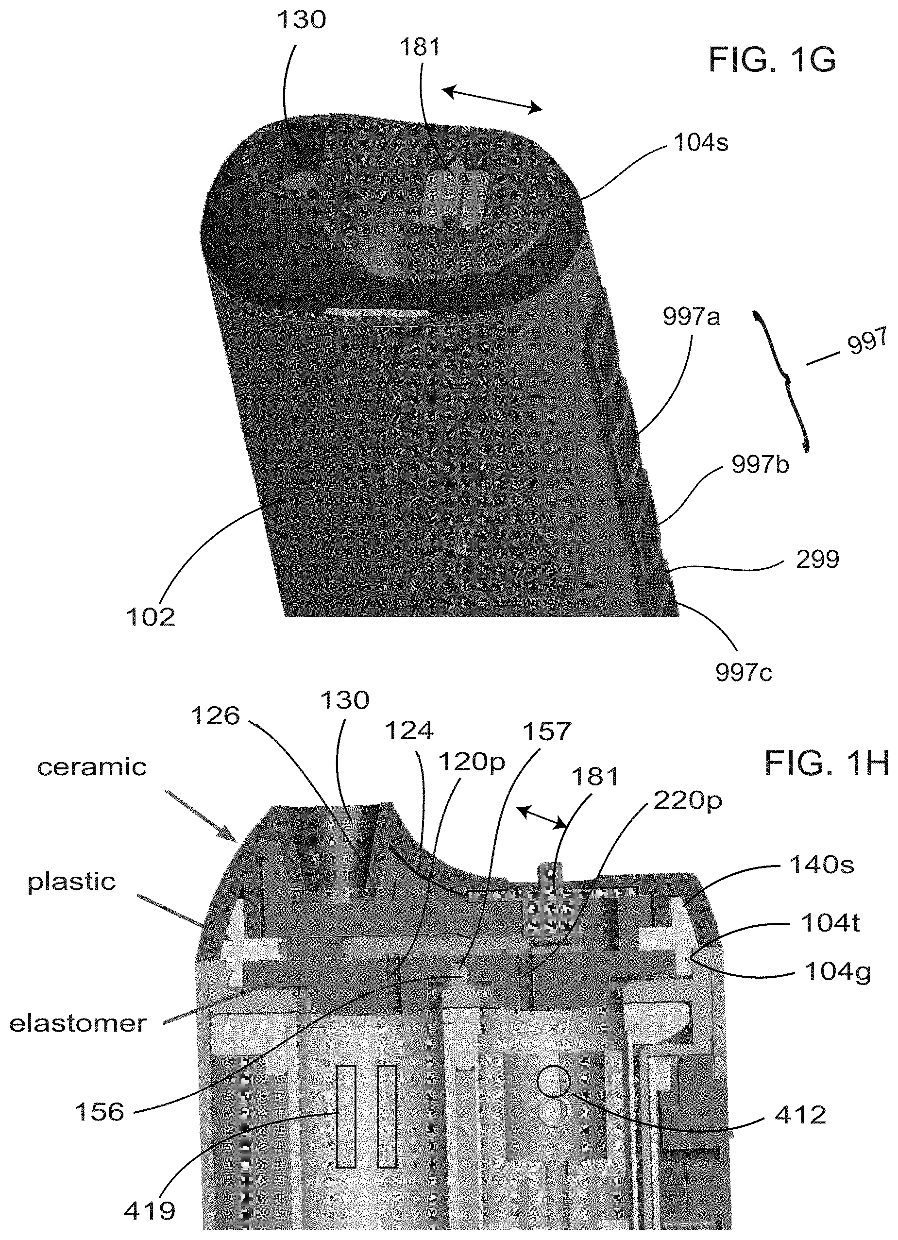
[0029] FIG. 1G illustrates a dual chamber vaporization device in accordance with a second embodiment of the invention an embodiment of the invention with a selective mouthpiece lid shown in a first orientation from a perspective view;
[0030] FIG. 1H illustrates a dual chamber vaporization device in accordance with a second embodiment of the invention an embodiment of the invention and in a cutaway view with a selective mouthpiece lid shown in a first orientation;
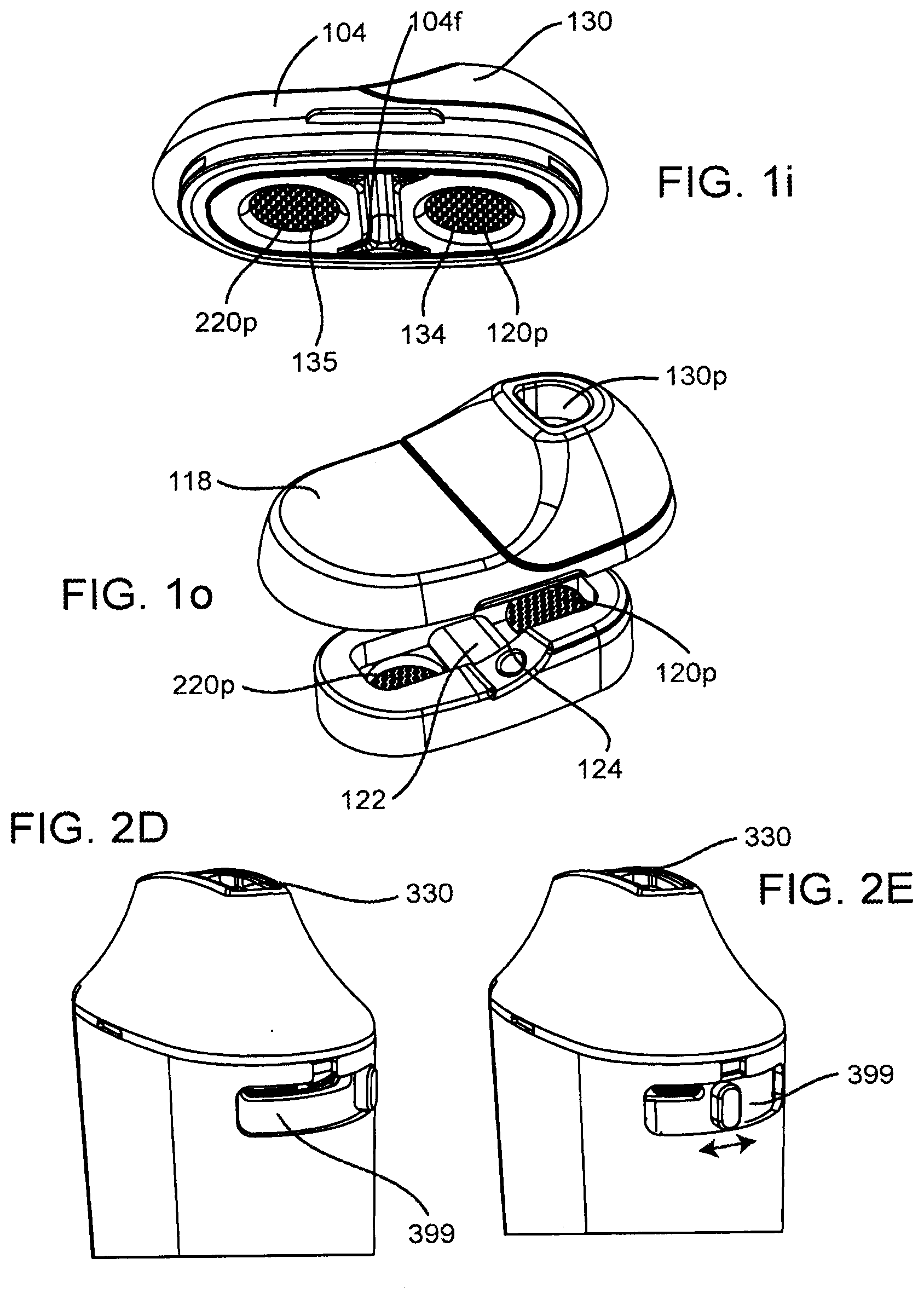
[0031] FIG. 1i illustrates a mouthpiece lid having a lid floor having a perforated floor section;
[0032] FIG. 1J illustrates a mouthpiece lid having a selector switch that is operate by pressing down from an user;
[0033] FIG. 1K illustrates an exploded view of a selective mouthpiece with an inner lid space shown;
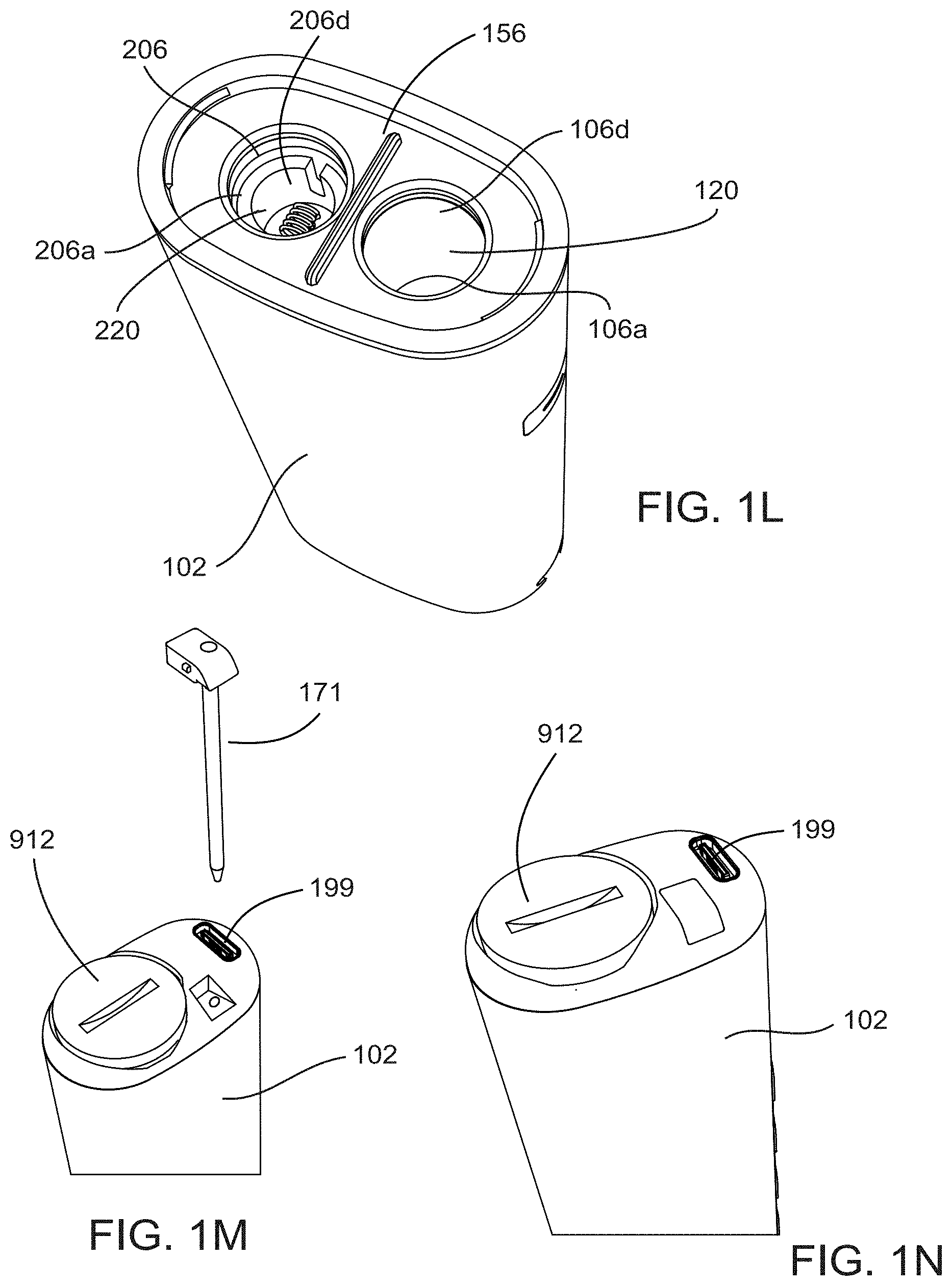
[0034] FIG. 1L illustrates a separator rib formed between a first heating chamber and a second heating chamber;
[0035] FIG. 1M illustrates a stir and load tool as a removable part of the dual chamber vaporization device;
[0036] FIG. 1N illustrates a door for removing of an energy storage module from the dual chamber vaporization device;
[0037] FIG. 1o illustrates a mouthpiece lid including a lid floor having a perforated floor section;
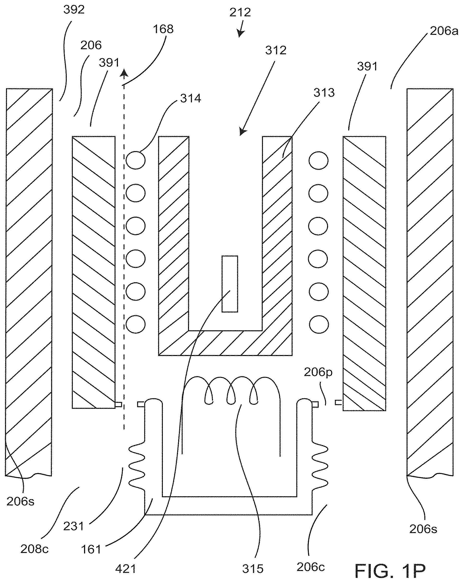
[0038] FIG. 1P illustrates a cutaway view of a second heating element assembly;
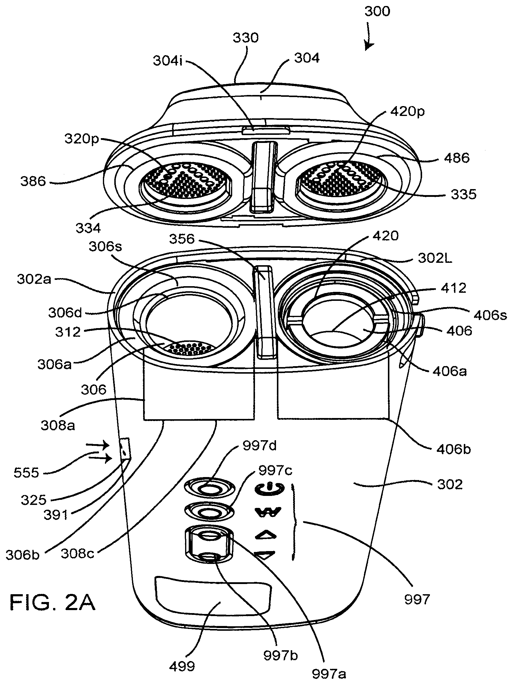
[0039] FIG. 2A illustrates a dual chamber vaporization device in accordance with a third embodiment of the invention;
[0040] FIG. 2B illustrates a dual chamber vaporization device in accordance with a third embodiment of the invention with an exploded view of the mouthpiece lid;
[0041] FIG. 2C illustrates an exploded of the mouthpiece lid with an air cooling assembly shown;
[0042] FIG. 2D illustrates a selectable airflow restrictor in an open orientation;
[0043] FIG. 2E illustrates a selectable airflow restrictor in a half open orientation;
[0044] FIG. 2F illustrates, a dual chamber vaporization device in accordance with a fourth embodiment is shown;
[0045] FIG. 3A illustrates a vaporization device in accordance with a fifth embodiment of the invention;
[0046] FIG. 3B illustrates a first conduction convection heating unit the CCHU that may be provided in accordance with an embodiment of the invention;
[0047] FIG. 3C illustrates a cutaway view a first conduction convection heating unit;
[0048] FIG. 3D illustrates a cutaway view of a conduction convection heating unit where a thermal radiator is in the form of a metal tube;
[0049] FIG. 3E illustrates a cutaway view of a first heating chamber with a thermal radiator visible therein;
[0050] FIG. 3F illustrates an example of a sketch of a potential temperature profile of the first and third sources of heat;
[0051] FIG. 3G illustrates a cutaway view of a conduction convection heating unit where a thermal radiator is in the form of a metal tube;
[0052] FIG. 3H illustrates a cutaway view of a conduction convection heating unit where a thermal radiator is in the form of a metal tube with third heat lines shown;
[0053] FIG. 3i illustrates an alternate thermal radiator where the third heating element for radiating heat;
[0054] FIG. 3J illustrates a conduction convection heating unit where a thermal radiator is in the form of a metal sponge;
[0055] FIG. 3K illustrates a conduction convection heating unit where a thermal radiator is in the form of a metal sponge in closeup;
[0056] FIG. 3L illustrates a thermal radiator in the form of the heatsink with metal fins uncoupled from a third heating element assembly;
[0057] FIG. 3M illustrates a thermal radiator in the form of the heatsink with metal fins coupled with a third heating element assembly;
[0058] FIG. 3N illustrates a thermal radiator in the form of a metal tube where the metal tube may be flared at an end proximate a base of a first heating chamber and in an exploded view;
[0059] FIG. 3o illustrates a thermal radiator in the form of a metal tube where the metal tube may be flared at an end proximate a base of a first heating chamber; and
[0060] FIG. 3P shows a partial cutaway of an air intake manifold and a manifold fluid flow channel; and,
[0061] FIG. 4A illustrates exemplary heating profiles for a first heating element assembly and a third heating element assembly.
DETAILED DESCRIPTION
[0062] Various apparatuses, methods and compositions are described below to provide an example of an embodiment of each claimed invention. No embodiment described below limits any claimed invention and any claimed invention may cover apparatuses and methods that differ from those described below. The claimed inventions are not limited to apparatuses, methods and compositions having all of the features of any one apparatus, method or composition described below or to features common to multiple or all of the apparatuses, methods or compositions described below. It is possible that an apparatus, method or composition described below is not an embodiment of any claimed invention. Any invention disclosed in an apparatus, method or composition described below that is not claimed in this document may be the subject matter of another protective instrument, for example, a continuing patent application, and the applicant(s), inventor(s) and/or owner(s) do not intend to abandon, disclaim, or dedicate to the public any such invention by its disclosure in this document.
[0063] Furthermore, it will be appreciated that for simplicity and clarity of illustration, where considered appropriate, reference numerals may be repeated among the figures to indicate corresponding or analogous elements. In addition, numerous specific details are set forth in order to provide a thorough understanding of the example embodiments described herein. However, it will be understood by those of ordinary skill in the art that the example embodiments described herein may be practiced without these specific details. In other instances, well-known methods, procedures, and components have not been described in detail so as not to obscure the example embodiments described herein. Also, the description is not to be considered as limiting the scope of the example embodiments described herein.
[0064] The terms "an embodiment," "embodiment," "embodiments," "the embodiment," "the embodiments," "one or more embodiments," "some embodiments," and "one embodiment" mean "one or more (but not all) embodiments of the present invention(s)," unless expressly specified otherwise.
[0065] The terms "including," "comprising," and variations thereof mean "including but not limited to," unless expressly specified otherwise. A listing of items does not imply that any or all of the items are mutually exclusive, unless expressly specified otherwise. The terms "a," "an," and "the" mean "one or more," unless expressly specified otherwise.
[0066] Embodiments described herein relate generally to vaporization of vaporizable material, such as phyto materials and phyto material products. Although embodiments are described herein in relation to vaporization of phyto material and phyto material products, it will be understood that other vaporizable materials, such as vaporizable nicotine products and/or synthesized vaporizable compounds, or combinations of vaporizable components may be used. For instance, various vaporizable products containing nicotine or plant derived extracts or oils, such as cannabis extract, CBD or terpene extracts and/or synthesized compounds may be used. Phyto material products may be derived from phyto materials such as the leaves or buds of cannabis plants.
[0067] Various methods of vaporizing phyto materials and phyto material products, such as cannabis products, are known. Phyto material is often vaporized by heating the phyto material to a predetermined vaporization temperature. The emitted phyto material vapor can then be inhaled by a user for therapeutic purposes.
[0068] Devices that vaporize phyto materials are generally known as vaporizers. In some cases, oils or extracts derived or extracted from the phyto materials may also be vaporized. For cannabis oils or extracts, temperatures in the range of about 500 to 700 degrees Fahrenheit may be applied to vaporize these phyto material products can generate phyto material vapor.
[0069] The phyto material vapor may be emitted at a temperature that is uncomfortable for a user to inhale. Accordingly, it may be desirable to cool the vapor prior to inhalation.
[0070] Referring to FIGS. 1A and 1B, a dual chamber vaporization device DCVD 100 in accordance with a first embodiment of the invention is shown and may include a device body 102 and a mouthpiece lid 104 may be moveably mounted to device body 102 (hinged or friction fit or slid on). Referring to FIGS. 1C and 1D, the DCVD 200 in accordance with a second embodiment of the invention may include a device body 102 and a selective mouthpiece lid 104s may be moveably mounted to device body 102 (hinged or friction fit or slid on).
[0071] The mouthpiece lid 104 or selective mouthpiece lid 104 may be movably mounted to the device body 102 by a friction fit connection (FIG. 1A), such as a snap fit connection formed by a tongue 104t and a groove 104g that mates to form a frictional fit connection). In other embodiments, the mouthpiece lid 104 may be movably mounted to the device body 102 by a hinged connection, or a slide-in groove connection (not shown) or a magnetic connection. For example, the mouthpiece lid 104 may be snapped on and off the body device 102 via the tongue 104t and groove 104g on the body device 102. For example, the body may have a lip around an outer edge. The mouthpiece lid 104 may be sized to fit within the lip and may be held in place by friction along the lip's edge. The mouthpiece lid 104 may contain an indent 104i or a tab to enable the user to remove the lid 104. A plurality of tongue and groove assemblies may be disposed for coupling of the mouthpiece 104, 104s with the de vice body 102. An elastomeric material seal may be provided as part of the mouthpiece lid 104 or selective mouthpiece lid 104 to provide for an approximately air tight seal for sealing of the mouthpiece lid 104 or selective mouthpiece lid 104 when engaged with the device body 102 in the first or second orientation. When a vacuum is created from the inhalation aperture 130 by the user, the elastomeric material seal facilitates of vapor transfer from the first and second heating chambers, 106 and 206, into the air-cooling assembly 124 or air missing assembly or air and vapor mixing assembly.
[0072] Referring to FIGS. 1A and 1B, the DCVD 100 and to FIGS. 1C and 1D, the DCVD 200 may include a device body 102 that may include a heating unit that includes a first heating chamber 106 and a first heating element assembly 112 (FIG. 1E) thermally coupled with the first heating chamber 106. A second heating chamber 206 and second heating element assembly 212 disposed within the second heating chamber 206. The first heating element assembly 112 may be positioned adjacent to the first heating chamber 106 and may be positioned about the first heating chamber for a conduction based vaporization device. The first heating element assembly 112 may be used to heat regions of the first heating chamber 106.
[0073] The device body 102 may have the heating unit that may include the second heating chamber 206 and the second heating element assembly 212 (FIG. 1E) may be found within the second heating chamber 206. The second heating element assembly 212 may be for heating of phyto material extract such as a wax or resin and may be a conduction style heating. The second heating element assembly 212 may include a resistive coil heating element 215 and may be disposed within a bowl or a bucket and the second heating chamber may be manufactured from a ceramic or glass or metal material or a plastic material with resistive heating proximate a floor of the second heating chamber 206. An exemplary second heating element assembly is shown in FIG. 2A.
[0074] Preferably the second heating chamber 206 and the second heating element assembly 212 is may be for operating at a higher temperature than the first heating element assembly 112. The first heating chamber 106 may be for use with ground phyto material and the second heating chamber 206 may be for use with phyto material extract. Optionally the first and second heating chambers are for a same type of phyto material, where both are for use with phyto material extract or both are for use with leaf phyto material.
[0075] Referring to FIG. 1E and FIG. 1N, the DCVD 100 and the DCVD 200 may include an energy storage module 116 such as a battery electrically coupled to the first heating element assembly 112 and to the second heating element assembly, 212. Energy storage module 116 may be used to energize the first heating element assembly 112 to heat the phyto material 419 within the first chamber cavity 120 through a conduction heating process and to energize the second heating element assembly 212 to heat the phyto material extract 421 within the second chamber cavity 220 using a conduction heating process.
[0076] The DCVD 100 and the DCVD 200 may include a control circuit 114 electrically coupled to the first heating element assembly 112 and the second heating element assembly 212 and energy storage module 116. The control circuit 114 may control the operation of the heating element assembly 112 and 212. The control circuit 114 may be used to activate/deactivate the heating element assembly 112 and 212 or to apply a pulse width modulated (PWM) signal to at least one of the heating element assemblies 112 and 212.
[0077] The control circuit 114 may also be used to adjust the settings of the DCVD 100 and DCVD 200, such as a first and second predetermined vaporization temperature. The control circuit 114 may control the flow of current through the heating element assembly 112 and 212 in accordance with a selected first and second predetermined vaporization temperature. For example the control circuit is used to set the first predetermined temperature using a temperature sensor or a PWM signal of to set the temperature within approximately about 350 Fahrenheit and 450 Fahrenheit and to set the second predetermined temperature to within approximately 450 Fahrenheit and 750 Fahrenheit.
[0078] As is shown in FIG. 1G and FIG. 1E, the control circuit 114 may also manage the operation of other components of DCVD 100 and DCVD 200 such as user input controls 997, such as buttons, such as a temperature up button 997a and a temperature down button 997b and a second heater button 997c to control power applied to the. Second heating element assembly 212.
[0079] Energy storage module 116 may be a rechargeable energy storage module, such as a battery or lithium battery or super capacitor. DCVD 100 and 200 may include a power supply port 199 (e.g. a USB-port or magnetic charging port) that allows the energy storage module 116 to be recharged. The energy storage module 116 may optionally be removable to allow it to be replaced through a battery removal port 912 or removable cap, as is shown in FIG. 1N. For instance, DCVD 100 may include one or more output components 299 (such as an LED display) that provide visual or audible signals to a user regarding the configuration and settings of DCVD 100. In some cases, DCVD 100 may include wireless communication modules 999 to allow the DCVD 100 to communicate with another wireless device such as a smartphone 998 or tablet. Referring to FIG. 1M, the a stir and load tool 171 is provided as a removable part of the DCVD to load and stir material 419, 421 into the heating chambers.
[0080] Referring to FIG. 1E, the first heating chamber 106 may include a first end 106a, a second end 106b. The first heating chamber 106 may also include one or more first chamber sidewalls 106s extending from the first end to the second end 106b with a first chamber third sidewall 108c capping the first heating chamber 106 proximate the second end 106b. The first chamber sidewalls 106s together with the first chamber third sidewall 108c may define a first chamber cavity 120 of the first heating chamber 106. Ground leaf phyto material may be loaded to the first chamber cavity 120 in preparation for vaporization. Referring to FIGS. 1A, 1B and 1E, the first heating chamber 106 may be cylindrical. The first heating chamber 106 includes a cylindrical sidewall 108a extending from the first end 106a to the second end 106b. The first heating chamber 106 may also include a first chamber third sidewall 108c capping the cylindrical heating chamber at the second end 106b that may also be referred to as a base or floor. This may allow air to flow into the first chamber cavity 120 of first heating chamber 106. First heating chamber 106 may also have an open upper end or side 106d proximate the first end 106a. The first chamber cavity 120 generally defines a volume within which a user may add ground leaf phyto material. For example, a user may add loose leaf phyto material 419 within the chamber cavity through the open upper end or side 106d proximate the first end 106a.
[0081] Referring to FIGS. 1A, 1B and 1E, the second heating chamber 206 may include a first end 206a, a second end 206b. The second heating chamber 206 may also include one or more second chamber sidewalls 206s extending from the first end to the second end 206b with a second chamber third sidewall 208c capping the second heating chamber 206 proximate the second end 206b. The second chamber sidewalls 206s together with the second chamber third sidewall 208c may define a second chamber cavity 220 of the second heating chamber 206. Where the second chamber third sidewall 208c may also be referred to as a base or floor. The second heating chamber 206 may be cylindrical and may be parallel with the first heating chamber 106. The second heating chamber 206 may include a cylindrical sidewalls 208a extending from the first end 206a to the second end 206b. The second chamber third sidewall 208c may be perforated. Second heating chamber 206 also has an open upper end 206d or side. Phyto material extract may be loaded into the second chamber cavity 220 through this open upper end 206d. In some embodiments the second heating chamber 206 also second chamber third sidewall 208c and the first heating chamber 106 also includes a first chamber third sidewall 108c are coupled to a common air intake manifold 191. The second chamber cavity 220 generally defines a volume within which a user may add phyto material extract for contacting the second heating element assembly 212.
[0082] FIGS. 1A, through 1D and FIG. 1L illustrates a separator rib 156 formed between the first heating chamber 106 first end 106a and the first end 206a of the second heating chamber 206 where the separator rib 156 may be for creating a raised protrusion between the first and second cavities, 120 and 220. This separator rib 156 may assist a user in loading of phyto material into either one of the chambers so that for example the loose leaf phyto material does be dispensed into second cavity 220. The separator rib 156 may also protrude into a separator rib cavity 157 (FIG. 1H, 1E) formed in the mouthpiece lid so that material from one chamber may have less of a likelihood of flow between chambers when the DCVD 100 and DCVD 200 is inverted.
[0083] The mouthpiece lid 104 may be moved between an open position (shown in FIGS. 1A, 1B) and a closed position (FIG. 1G, 1H, 1E, 1K) showing the selective mouthpiece lid 104s). In the open position, the upper end of the first chamber cavity 120 may be exposed. This may allow a user to load phyto material 419 into the first heating chamber 106 and phyto material extract 421 into the second heating chamber 206 for vaporization and/or dispose of vaporized phyto material therefrom. The mouthpiece lid 104 may also be rotated about a vertical axis/central axis 512 where the mouthpiece portion proximate the first and second cavities, 120 and 220 may have a symmetry and may snap or frictionally engage with the body 102 in either one of two orientations. FIG. 1A shows a first orientation and FIG. 1B shows a second orientation.
[0084] Referring to FIG. 1A, in the first orientation the mouthpiece lid 104 may include a first perforated floor section 120p to be aligned with the first end 106a of the first heating chamber 106 and a second perforated floor section 220p may be aligned with the first end 206a of the second heating chamber 206. Referring to FIG. 1B, in the second orientation the mouthpiece lid 104 may include the first perforated floor section 220p to be aligned with the first end 106a of the first heating chamber 106 and a first perforated floor section 120p may be aligned with the first end 206a of the second heating chamber 206. When the mouthpiece lid 104 is moved to the closed position and in the first orientation, the mouthpiece lid 104 and the first heating chamber 106 and the second heating chamber 206 may enclose the first and second chamber cavities 120, 220. When the mouthpiece lid 104 is moved to the closed position and in the second orientation, the mouthpiece lid 104 and the first heating chamber 106 and the second heating chamber 206 may enclose the first and second chamber cavities 120, 220.
[0085] Referring to an exploded view of the mouthpiece lid as shown in FIG. 1K and FIG. 1o and FIG. 1i, the mouthpiece lid 104 may also include a lid floor 104f having a perforated floor section 104p with an inner lid space 122 defined between the outer wall 104w and the lid floor 104f with an inhalation aperture defined 130 in the outer wall 104w, the inhalation aperture 130 fluidly coupled to the inner lid space 122 and downstream from the lid floor 104f. In the closed position, the lid 104 and the first and second heating chambers, 106 and 206 enclose the first and second chamber cavities, and at least a portion of the perforated floor section 104p overlies the first and second chamber cavities 120, 220 proximate the first ends 106a and 206a, whereby the first and second chamber cavities 120, 220 and the inner lid space 122 are fluidly connected. In the closed position, at least one of the first and second heating element assemblies 112 and 212 are energizable to heat phyto material disposed within the chamber cavities to a predetermined first and second vaporization temperatures for creating a first vapor and a second vapor; and to define a vapor flow path from the first and second chamber cavities through the perforated floor 104f to the inner lid space and the inhalation aperture for the first vapor and second vapor to propagate through the inhalation aperture 130.
[0086] Referring to FIGS. 1i and 1o, the first perforated floor section 120p of mouthpiece lid 104 may also include apertures or first pores 134 throughout its surface and the second perforated floor section 220p of mouthpiece lid 104 may also includes apertures or second pores 135 throughout its surface. When in the first orientation and when the mouthpiece 104 is in the closed position the pores 134 may permit first vapor to pass from the first chamber cavity 120 to the inner lid space 122 through the first perforated floor section 120p and for second vapor to pass from the second chamber cavity 220 to the inner lid space 122 through the second perforated floor section 220p. When in the second orientation and when the mouthpiece 104 is in the closed position the pores 134 may permit a second vapor to pass from the second chamber cavity 220 to an inner lid space 122 through the first perforated floor section 120p and for first vapor to pass from the first chamber cavity 120 to the inner lid space 122 through the second perforated floor section 220p.
[0087] The size of first and second pores 134, 135 may be selected to inhibit non-vaporized pieces or flakes of the phyto material from passing into the air cooling assembly 124 and out the inhalation aperture 130 into the user's mouth. Thus, the pores 134 may also provide a filtering action. The pores 134, 135 in conjunction with the air cooling assembly 124 may also provide a filtering action through a shape of the air cooling assembly 124 that uses a curved air path or non linear air path. In some embodiments a first air cooling path length formed between the first perforated floor section 120p and the inhalation aperture 130 may be shorter than a second air cooling path length formed between the second perforated floor section 220p and the inhalation aperture 130. As such the user may be able to adjust between the first orientation of the mouthpiece lid 104 and the second orientation of the mouthpiece lid 104 in order to select from which cavity additional vapor cooling is preferred. The first air cooling path length may provide for a reduced amount of vapor cooling as compared with the second air cooling path length.
[0088] An additional air cooling assembly may comprise a porous mesh that may be inserted proximate the mouthpiece for receiving of the vapors emitted from either of the chambers for providing of additional vapor cooling to at least one of the first air cooling path length and second air cooling path length. The size of pores 134. 135 may depend on the form of the phyto material being used. In some embodiments, the pores 134, 135 may be between 0.1 and 0.6 mm. For example, the pores 134, 135 may be between 0.025 and 0.3 mm. In some embodiments, the pores 134 may be between 0.05 and 0.2 mm. In some embodiments the first perforated floor section 120p and the second perforated floor section 220p may have pores of varying sizes. The size of pores 134, 135 may be selected to inhibit non-vaporized pieces or flakes of the phyto material from passing into the air cooling assembly 124 and out the inhalation aperture 130 into the user's mouth. Thus, the pores 134, 135 may also provide a filtering action. The pores 134 in conjunction with the air cooling assembly 124 may also provide a filtering action through a shape of the air cooling assembly 124 that uses a curved air path or a tortuous air path.
[0089] First vapor from the first chamber cavity 120 may enter the air inlet of the air cooling assembly 124 at a first temperature T1 and exit through the mouthpiece 130 at a second temperature T2 that is lower than the first temperature T1. This may provide a user with a more comfortable, and safer, temperature of vapor for inhalation. Second vapor from the second chamber cavity 220 may enter the air cooling assembly 124 at a third temperature T3 and exit through the mouthpiece 130 at a fourth temperature T4 that is lower than the third temperature T3. This may provide a user with a more comfortable, and safer, temperature of at least one of first and second vapor for inhalation.
[0090] In the open position (shown in FIGS. 1A to 1D), the chamber cavities 120, 22 are open to the external environment 144 and the phyto material 419, 421 may be loaded into the first chamber cavity 120 and the second chamber cavity 220 of the first heating chamber 106. As discussed above, loose leaf phyto material 419 may be distributed within the first chamber cavity 120 and phyto material extract is placed in proximity of the second heating element assembly.
[0091] In the closed position the mouthpiece lid 104 (FIG. 1A, 1B) or the selective mouthpiece lid 104s (FIG. 1C, 1D) and device body 102 may enclose the first chamber cavity 120 and the second chamber cavity 220. In the closed position, at least a portion of the perforated floor 120p covers the first chamber cavity 120 and at least a portion of the second perforated floor 220p covers the second chamber cavity 220. In this position, the first chamber cavity 120, 220 and the inner lid space 122 are in fluid communication via the pores 134, 135 and the first and second perforated floor 120p, 220p.
[0092] Further, when in the closed position, the heating element assemblies 112, 212 may be selectively energized to heat the phyto material 419 in the first chamber cavity 120 to the first predetermined temperature to vaporize the phyto material 419 and selectively heat the heat the phyto material 421 in the second chamber cavity 220 to a second predetermined temperature to vaporize the phyto material extract 421.
[0093] When the user inhales from the inhalation aperture 104, ambient air 125 may be drawn from the external environment 555 into the first chamber cavity 120 through the first chamber third sidewall 108c via the first chamber pores 106p in fluid communication with the air intake manifold 191. While in the first chamber cavity 120, ambient air is mixed with the vaporized phyto material and is the first vapor drawn by the inhalation through the air cooling assembly and out the inhalation aperture 130 and ambient air 555 may be drawn from the external environment 144 in fluid communication with the air intake manifold 191 into the second chamber cavity 220 through the second chamber third sidewall 208c via the second chamber pores 206p. While in the second chamber cavity 220, ambient air is mixed with the vaporized phyto material extract and is the second vapor then drawn by the inhalation through the air cooling assembly and out the inhalation aperture 130.
[0094] Referring to FIGS. 1K and 1G and 1H, where FIG. 1H shows a cutaway side view of the selective mouthpiece lid 104s and the heating unit and FIG. 1H shows the selective mouthpiece coupled with the device body and FIG. 1K shows an exploded proportional view of the selective mouthpiece lid. A selective mouthpiece lid 104s in an exploded view where a selector switch 181 is shown as well as a selector slider valve 182, the selector slide valve for selectively closing second pores 135, when the second pores 135 are selectively closed then inhalation from the inhalation aperture through the second perforated floor section 220p is substantially blocked. The selector switch 181 protrudes past the selective mouthpiece lid 104s so that it allows for easy actuation by the user. In some embodiments (FIG. 1J) the selector switch 181 is only operated when it is depressed by the end user (second pores 135 are selectively closed during applied pressure and working against a spring force or a material deforming force) and when released second pores 135 are selectively open. In some embodiments the selector switch 181 rests in its current state, so when it is selected to close second pores 135, the second pores 135 are selectively closed then and the switching action remains in position until altered from this state. The selective mouthpiece lid 104s may be coupled with the device body 102 in either of the first or second orientations as determined by the user. With the selective mouthpiece 104s either both or one of the chambers may be selected for having vapor drawn therefrom.
[0095] Referring to FIGS. 1F and 1E, in some embodiments, such as shows for the DCVD 100 and DCVD 200, the common air intake manifold 191 receives ambient air 555 through an ambient air input port 125 and this ambient air is split by the air intake manifold 191 into a first airpath 167 that that may be for propagating through the first heating chamber 106 through the a first chamber third sidewall 108c via first chamber pores 106p a and a second airpath 168 may be for propagating into the second heating chamber 206 through the third sidewall 208c via second chamber pores 206p.
[0096] Referring to FIGS. 1O and 1K. the first and second airpaths 167 and 168 both meet at the air cooling assembly 124 when the mouthpiece lid 104 or selective mouthpiece lid 104s is in the closed position in either the first or second orientation. In some embodiments the common air intake manifold 191 receives ambient air 555 and is split by the air intake manifold 191 into the first airpath 167 that is for propagating through the first heating chamber 106 and the second airpath 168 for propagating through the second heating chamber 206 where the first and second airpaths selectively meet at the air cooling assembly 124 when the selective mouthpiece lid 104s is in the closed position, unless the selective mouthpiece lid 104s has the selector switch 181 oriented for selectively closing second pores 220p from having air flow through the pores to the air cooling assembly 124.
[0097] Referring to FIG. 1E, a size of the first chamber pores 106p and size of the second chamber pores 206p may vary depending on the form of the phyto material to be vaporized. An optimal pore size may depend on the fineness of the phyto material loaded into the first chamber cavity 120 (i.e. the finer the grind, the smaller the pores 132). Smaller pores 106p may inhibit non-vaporized pieces of the phyto material from falling through first chamber third sidewall 108c via the first chamber pores 106p and into the common air intake manifold. For the second heating chamber 206 the second chamber pores 206p may also be of a smaller or larger size than the first chamber pores 106p.
[0098] In some embodiments a removable drawer 278 may be provided for collecting phyto material that falls through the first chamber pores 106p, where in some cases there is a tradeoff between the pore size as well as airflow. The smaller the pore size the more the airflow is restricted. As such having a removable drawer 278 facilitates cleaning of crumbs or phyto material that has fallen out of the heating chamber through the first chamber pores 106p. When the removable drawer is removed is also facilitates cleaning of any residue or wax building that may have propagated from the second heating chamber through the second chamber pores 206p into the common air intake manifold 191. In some embodiments, the pores 106p and pores 206p may be between 0.1 and 0.6 mm. For example, the pores 106p and pores 206p may be between 0.025 and 0.3 mm. In some embodiments, the pores 106p and pores 206p may be between 0.3 and 0.9 mm. In some embodiments, such as for the second heating chamber, a porous ceramic or porous metal is envisaged for creating of the second chamber pores 206p.
[0099] Referring to FIG. 1E, in some embodiments, the first heating chamber may include a conduction heating system, the first heating element assembly 112 may be positioned to at least partially surrounding the exterior of the first heating chamber 106. The first heating element assembly 112 may be energized to emit heat. The heat from the first heating element assembly 112 may heat the first chamber cavity 120, and in turn the phyto material positioned in the first chamber cavity 120. In some embodiments, the first heating element assembly 112 may include one or more resistive heating elements sintered with the ceramic heating chamber. In some embodiments the heating element assembly 112 includes a coil heating element 115. The coil heating element 115 may be activated by directing current through the coil 115. The coil 115 may then emit heat. Heat from the first heating element assembly 112 may radiate into the first heating chamber 106 to heat phyto material 419 in the first chamber cavity 120 to a first predetermined vaporization temperature. Phyto material vapor may then be emitted from the heated material. In some embodiments an insulating layer is provided between the two heating chambers.
[0100] The first heating element assembly 112 may be formed from a silk screen resistive film heating whereby a heating element is formed from a resistive ink that is integrated and sintered with the heating chamber being manufactured from ceramic or where it's a resistive wire wrapped about an outside of the heating chamber or the heating chamber is manufactured from deep drawn or stamped or cast metal and the first heating element assembly 112 is printed onto the heating chamber and integrated therewith where in the case where the first heating chamber 106 is tubular in shape, a Thick Film Tubular Heater (TFH) is printed on stainless steel substrate by using a thick-film screen printing process to print insulating materials, heating resistors, conductors and then a glass protective glaze. In the case of a rectangular heating chamber or a heating chamber with flat walls, a Thick Film Flat Heater (FTH) process may be used. The FTH may be printed on stainless steel substrate by using a thick-film screen printing process to print insulating materials, heating resistors, conductors, glass protective glazes. A capton heater may also be envisaged with a capton resistive heating element wrapped about the first heating chamber 106.
[0101] For a convection heating system being utilized within the DCVD 100, 200, a third heating element assembly may be provided in the form of a thermal radiator 1806 (FIG. 3B) for receiving of incoming air and for heating the incoming air through a convective heat transfer process where the thermal radiator 1806 may be energized to emit heat and the heat from the thermal radiator 1806 may heat the phyto material positioned in the first chamber cavity 120 through a convective heating process. The thermal radiator 1806 may or may not be utilized in conjunction with the first heating element assembly 112. Embodiments of convection heating system are further described in FIGS. 3A, 3B, 3C.
[0102] Referring to FIG. 1P, in some embodiments, the second heating element assembly 212 may include one or more resistive heating elements as the second heating element assembly 215 removably (using releasable electrical coupling 161 (FIG. 1P, 1E)) or fixed mounted within the second heating chamber 220. In some embodiments the second heating element assembly 212 includes a resistive coil heating element 315, which may be in the form of a pancake resistive coil or a spiral coil or a printed coil. The resistive coil heating element 315 may be activated by directing current through the coil 315. The coil 315 may then emit heat. Heat from the heating element assembly 212 may radiate into the second heating chamber 206 to heat phyto material extract 421 in the second chamber cavity 220 to a second predetermined vaporization temperature through direct contact (shown more clearly in FIG. 1H) with the phyto material extract. Phyto material extract vapor as the second vapor may then be emitted.
[0103] The second heating element assembly 212 may be removable from the second heating chamber with electrical contacts that are pin or screw or magnetic based so that in the case it fails or gets dirty it may be removed. The resistive coil heating element 215 may be directly in contact with the phyto material extract or as shown in FIG. 1H in a cutaway side view. Referring to FIG. 1P, the resistive coil heating element 315 may be in thermal contact with a glass or ceramic or quartz dish or bucket, generally referred to as a bucket 313 having an inner volume 312, that may be surrounded by porous ceramic or porous metal 314 material or an air gap or a combination of an insulating material and air channel formed between an outside surface of the bucket 313 or dish and an inside surface of a shroud assembly 391 and an air gap between the that generally allows for air to propagate about an outside diameter or outside shape of the bucket 313 and an inside surface of the shroud assembly 391 that faces the bucket 313. The heating element assembly and the 215 the bucket 313 are held in place and preferably somehow thermally insulated from the shroud assembly 391. The electrical contacts that are pin or screw or magnetic base are mechanically coupled with the shroud assembly 391.
[0104] The second airpath 168 may be for propagating into the second heating chamber 206 to the first end 206a through second chamber third sidewall 208c via the second chamber pores 206p and at least one of a gap 392 between walls of the second chamber cavity 220 and an outside surface of the shroud assembly 391 and through the porous ceramic or porous metal 314 material or an air gap or a combination of an insulating material and air channel formed between an outside surface of the bucket 313 and an inside surface of a shroud assembly 391. Air propagating through the second heating chamber 206 in accordance with either of the above means may provide for thermally insulating of the glass bucket from the shroud assembly as well as may assist in thermally insulating (at least partially) of the shroud assembly from inner walls of the second heating chamber. This may facilitate a quicker heating of the glass bucket. Advantageously the glass bucket may provide for a cleaner vaporization of the phyto material extracts as the second vapor as opposed to the phyto material extracts being paced directly onto the coil heater 212.
[0105] A releasable electrical coupling 161 (FIG. 1P, 1E) may be provided for the removably mounting of the second heating element assembly 221 from the device body 102. This facilitates removing of the second heating element assembly 221 when it may need replacement. Preferably the resistive wire is insulated from sidewalls of the second heating chamber 206. so that a larger amount of thermal energy from the resistive wire is transferred to the phyto material extract that is disposed within the bucket rather than to sidewalls of the second heating chamber 206 and also potentially into the shroud assembly. For an extract conduction heating system, the second heating element assembly 212 may be positioned to heat an interior of the second heating chamber 206. In some embodiments the shroud assembly and the bucket may be cylindrical in shape and coaxial with one another.
[0106] Referring now to FIGS. 2A-2E, a DCVD 300 in accordance with a third embodiment shown. The DCVD 300 300 is another example of a vaporization device usable to vaporize vaporizable material. Vaporization device 300 having similar structure and/or performing similar function as those in the example vaporizer device 100 of FIGS. 1A through 1P are numbered similarly, with the reference numerals incremented by 200.
[0107] Referring to FIG. 2A the DCVD 300 may include a device body 302 that may include a heating unit that includes a first heating chamber 306 and a first heating element assembly 312 thermally coupled with the first heating chamber 306 and second heating element assembly 412 disposed within the second heating chamber 406. The first heating element assembly 312 may be positioned adjacent to the first heating chamber 306 and may be positioned about the first heating chamber for a conduction based vaporization device. The first heating element assembly 312 may be used to heat regions of the first heating chamber 306 for heating of a first material for vaporization disposed therein with a first source of heat.
[0108] The device body 302 may have a heating unit that includes the second heating chamber 406 and the second heating element assembly 412. The second heating element assembly 412 may be for heating of phyto material extract, or a second material for vaporization, such as a wax or resin and may be a conduction style heating for directly conducting of heat to the phyto material extract from the second heating element assembly 412. The second heating element assembly 412 may include a resistive coil heating element 415 thermally coupled with a bowl or a bucket for containing of the phyto material extract and sidewalls of the second heating chamber may be manufactured from a ceramic or glass or metal. The bowl or a bucket for containing of the phyto material extract may be manufactured from a ceramic or glass or metal with a resistive heating from a floor of the ceramic or glass or metal bucket. The second heating chamber 406 may include a first end 406a, a second end 406b. The second heating chamber 406 may also include one or more second chamber sidewalls 406s extending from the first end 406a to second end 406. The sidewalls may define a second chamber cavity 420 of the second heating chamber 406. Phyto material extract may be loaded to the second heating element 412 of the second chamber cavity 420 in preparation for vaporization. The second heating element assembly may be disposed within the second heating chamber for applying a source of a second heat through a thermal conduction process to the second material for vaporization.
[0109] The first heating chamber 306 may be cylindrical. The first heating chamber 306 may include first chamber sidewalls 306s, extending from the first end 306a to the second end 306b, which may be a cylindrical sidewall 308a extending from the first end 306a to the second end 306b. The first heating chamber 306 may also include a first chamber third sidewall 308c capping first heating chamber 306 at the second end 306b that may also be referred to as a base or floor. This may allow air to flow into the first chamber cavity 320 of first heating chamber 306. First heating chamber 306 may also have an open upper end or side 306d. Phyto material may be loaded into the first chamber cavity 320 through this open upper end 306d.
[0110] In some embodiments the second heating chamber 406 and the second heating element assembly 412 is may be for operating at a higher temperature than the first heating element assembly 312. The first heating chamber 306 may be for use with ground phyto material and the second heating chamber 406 may be for use with phyto material extract.
[0111] The mouthpiece lid 304 may be moved between an open position (shown in FIG. 2A) and a closed position (FIG. 2D). In the open position, the upper end of the first chamber cavity 320 may be exposed. This may allow a user to load phyto material 419 into the first heating chamber 306 and phyto material extract 421 into the second heating chamber 406 for vaporization and/or dispose of vaporized phyto material therefrom. The mouthpiece lid 404 may also be rotated about a vertical axis/central axis 512 where the mouthpiece portion proximate the first and second cavities, 320 and 420 may have a symmetry and may magnetically or frictionally engage with the body 302 in either one of two orientations. In this third embodiment the mouthpiece lid 304 may be substantially symmetric about the vertical axis or central axis 512.
[0112] Referring to FIG. 2A, in the first orientation the mouthpiece lid 304 may include a first perforated floor section 320p to be aligned with the first end 306a of the first heating chamber 306 and a second perforated floor section 420p may be aligned with the first end 406a of the second heating chamber 406. Referring to FIG. 2B, in the second orientation the mouthpiece lid 304 may include the first perforated floor section 420p to be aligned with the first end 306a of the first heating chamber 306 and a first perforated floor section 320p may be aligned with the first end 406a of the second heating chamber 406. When the mouthpiece lid 304 is moved to the closed position and in the first orientation, the mouthpiece lid 304 and the first heating chamber 306 and the second heating chamber 406 may enclose the first and second chamber cavities 320, 420. When the mouthpiece lid 304 is moved to the closed position and in the second orientation, the mouthpiece lid 304 and the first heating chamber 306 and the second heating chamber 406 may enclose the first and second chamber cavities 320, 420.
[0113] FIG. 2N illustrates the mouthpiece lid 304 in an exploded perspective view and FIG. 2C from an exploded side view. Referring to FIG. 2A, the first perforated floor section 320p of mouthpiece lid 304 may also include apertures or first pores 334 throughout its surface and the second perforated floor section 420p of mouthpiece lid 304 may also include apertures or second pores 335 throughout its surface. When in the first orientation and when the mouthpiece 304 is in the closed position the first pores 334 may permit first vapor or first aerosol to pass from the first chamber cavity 320 to an inner lid space 322 (FIG. 2B) through the first perforated floor section 320p and for second vapor or second aerosol to pass from the second chamber cavity 420 to an inner lid space 322 through the second perforated floor section 420p having second pores 335. When in the second orientation and when the mouthpiece 304 is in the closed position the first pores 334 may permit second vapor to pass from the second chamber cavity 420 to an inner lid space 322 through the first perforated floor section 320p and for the first vapor to pass from the first chamber cavity 320 to the inner lid space 322 through the second perforated floor section 420p. The first heating element assembly may result in the first material for vaporization to generate a first aerosol and the third heating element assembly may result in the first material for vaporization to generate a third aerosol where at least one of the second and third aerosol form the first vapor.
[0114] The size of first pores 334 and second pores 335 may be selected to inhibit non-vaporized pieces or flakes of the phyto material from passing into the air cooling assembly 324 and out the inhalation aperture 330 into the user's mouth. Thus, the first pores 334 may also provide a filtering action. The first pores 334 in conjunction with optionally the air cooling assembly 324 may also provide a filtering action through a shape of the air cooling assembly 324 may provide for a mixing air path or a cascade mixing air path or a tortuous air path. In some embodiments a first air cooling path length formed between the first perforated floor section 320p and the inhalation aperture 330 may be shorter than a second air cooling path length formed between the second perforated floor section 420p and the inhalation aperture 330 and in some embodiments the first and second cooling path lengths combine towards the mouthpiece to mix vapors emitted from both heating chambers as part of a mixing air path. The air cooling assembly 324 may be manufactured from an elastomeric material or a combination of an elastomeric material and a metal material where in conduction with the inner lid space 322, vapors propagating from each of the perforated floor sections, 320p, 420p, may be cooled. In some embodiments the mouthpiece 304 may be manufactured from a metal or aluminum material. First and second vapors may lose heat to the air cooling assembly 324 as well as the mouthpiece 304.
[0115] The user may be able to adjust between the first orientation (FIG. 2A) of the mouthpiece lid 304 and the second orientation (FIG. 2B) of the mouthpiece lid 304 in order to select from which cavity 320, 420 additional vapor cooling is preferred. The size of first pores 334 and 335 may depend on the form of the phyto material being used and may not be equal in all cases. In some embodiments, the first pores 334 may be between 0.1 and 0.6 mm. For example, the first pores 334 may be between 0.025 and 0.3 mm. In some embodiments, the first pores 334 may be between 0.05 and 0.2 mm and in other cases 0.8 mm. In some embodiments the first perforated floor section 320p and the second perforated floor section 420p may have first pores 334, 335 of varying sizes. The size of first pores 334 may be selected to inhibit non-vaporized pieces or flakes of the phyto material from passing into the air cooling assembly 324 and out the inhalation aperture 330 into the user's mouth. Thus, the pores 134 may also provide a filtering action as well as somewhat cooling action. The first pores 334 in conjunction with the air cooling assembly 324 may also provide a filtering action through a shape of the air cooling assembly 324 that uses the mixing air path. A combined length of the airpath long which air and vapor travels is greater than a distance between the inhalation aperture 330 and a mouthpiece base or height 304h of the mouthpiece 304.
[0116] Referring to FIG. 2A. a first airpath 267 and a second airpaths 268 both meet at the air cooling assembly 324 when the mouthpiece lid 304 is in either the first or second orientation. In some embodiments an air intake manifold 391 receives ambient air 555 through a first ambient air input port 325 and air flows through the first airpath 267 for propagating through the first heating chamber 306. Ambient air 555 may originate to the second airpath 268 via a second ambient air input port 326 for propagating across the second heating chamber 406 proximate the first end 406a and approximately radially with respect to the heating unit 412 for skimming vapors proximate the first end 406a that are emitted by the second heating unit 412 with the where the first and second airpaths 267 and 268 meet at the air cooling assembly 324 when the mouthpiece lid 304 is in the closed position. In some embodiments the second airpath 268 other than originates from the air intake manifold 391. The second ambient air input port 326 may include a selectable airflow restrictor 399 (FIGS. 2B, 2D and 2E) where in some embodiments the selectable airflow restrictor 399 is movable to approximately restrict incoming ambient airflow into the second airpath 268 or to allow approximately maximal airflow into the second airpath 268. The selectable airflow restrictor 399 may operate from an opening of approximately 0.1 mm{circumflex over ( )}2 in area to an opening of approximately 5 mm{circumflex over ( )}2 in area for the second ambient air input port 326. The selectable airflow restrictor 399 may be a rotating collar about sidewalls 406s of the second heating chamber 406 or in some embodiments it may be a slider for varying an aperture through which the second airpath 268 originates for controlling an area of the second ambient air input port 326.
[0117] The user may be able to selectively control the airflow incoming into the second heating chamber 406 through the selectable airflow restrictor 399 and to control the airflow incoming into the first heating chamber 306 using the first ambient air input port 325. Through blocking of the first ambient air input port 325, for example by using a finger, substantially little airflow flows into the first heating chamber 306. Through blocking of the second ambient air input port 326 for example by using the selectable airflow restrictor 399 such that it may be oriented so that little airflow flows into the second heating chamber 406. The user may then able to control amounts of vapor being emitted from each of the first and second heating chambers.
[0118] The mouthpiece lid 304 may be movably mounted to the device body 302 by a friction fit connection such as that described for the first and second embodiments. In other embodiments, the body 302 may have a protruding lip 302L around an outer edge 302a. The mouthpiece lid 304 may be sized to fit within the protruding lip 302L and outer edge and may be held in place by friction along the protruding lip edge, in other embodiments a magnetic coupling may be realized between the mouthpiece lid 304 and the device body 302. In some embodiments a first ring magnet may be disposed about the mouthpiece lid 304 may about the first perforated floor section 320p to be aligned with the first end 306a of the first heating chamber 306 and a second ring magnet may be disposed second about the second perforated floor section 420p to be aligned with the first end 406a of the second heating chamber 406. The ring magnets may engage the first end 306a of the first heating chamber 306 and may engage the first end 406a of the second heating chamber 406 where these surfaces may include a metallic surface for engaging with the ring magnets. First and second elastomeric seals 386 and 486 may be formed about the first and second perforated sections 320p and 420p of the mouthpiece lid 304 for sealing the mouthpiece lid 304 against the device body 302 when the mouthpiece lid 304 is frictionally or magnetically engaged with the device body 302 for allowing a user to create a vacuum at the inhalation aperture 330 for sucking of vapors originating from at least one of the first and second heating chambers 306 and 406. The elastomeric material seals 386 and 486 may facilitates of vapor transfer from the first and second heating chambers, 306 and 406, into the air cooling assembly 324. The mouthpiece lid 304 may contain an indent 304i or a tab to enable the user to remove the mouthpiece lid 304.
[0119] Referring to FIG. 2B, a separator rib 356 formed between the first heating chamber cavity 320 first end 306a and the first end 406a of the second heating chamber cavity 420 where the separator rib 356 may be for creating a raised protrusion between the first and second cavities, 320 and 420. This separator rib 356 may assist a user in loading of phyto material into either one of the chambers so that for example the loose leaf phyto material does not go into an undesired heating chamber cavity. The separator rib 356 may also protrude into a separator rib cavity 357 that may be formed as a cavity in the mouthpiece lid 304 so that material from one chamber may have less of a likelihood of flow between chambers when the DCVD 300 is inverted. In some embodiments the separator rib 356, 156 may be raised about 3 mm in height and have a length of about 10 mm and a width of about 3 mm. In some embodiments the separator rib 356 may be made from a magnetic metal and there may be magnets inside the mouthpiece lid that engage the separator rib 356 when inserted into the separator rib cavity 357.
[0120] The DCVD 300 may also include a control circuit similar to the control circuit 114 may also manage the operation of other components of DCVD 300 such as user input controls 997, such as buttons, such as a temperature up button 997a and a temperature down button 997b and a second heater button 997c to control power applied to the second heating element assembly 412 as well as a power ON/OFF button 997d. The DCVD 300 may include one or more output components 499 (such as an OLED display) that provide visual signals to a user regarding the configuration and settings of DCVD 300. The second heating element assembly 412 may be similar to the second heating element assembly 212.
[0121] In some embodiments, the heating element assembly may be configured to heat the phyto material to a first predetermined vaporization temperature. The first predetermined vaporization temperature may vary depending on user preference and/or the form of the phyto material. For example, loose leaf phyto material may be vaporized at a predetermined vaporization temperature in a range between about 320 degrees Fahrenheit and about 450 degrees Fahrenheit. The user may be able to adjust the first predetermined vaporization temperature using input controls. The control circuit 114 may then control the current through the first heating element to adjust the first vaporization temperature.
[0122] In some embodiments, the heating element assembly may be configured to heat the phyto material extract to a second predetermined vaporization temperature. The second predetermined vaporization temperature may vary depending on user preference and/or the form of the phyto material extract. For example, phyto material extract may be vaporized at a second predetermined vaporization temperature in a range between about 450 degrees Fahrenheit and about 750 degrees Fahrenheit. The user may be able to adjust the second predetermined vaporization temperature using input controls. The control circuit 114 may then control the current through the second heating element to adjust the second vaporization temperature. In some embodiments the battery 116 may have the heating chambers extend along its length and may share a common central axis and the heating chambers may be oriented parallel with each other and inline with the battery. In some embodiments the heating chambers may be oriented perpendicular with a long axis of the battery and a mouthpiece extending across the battery along its length and proximate a battery removal port 912.
[0123] Referring now to FIG. 2F, a DCVD 500 in accordance with a fourth embodiment is shown. The DCVD 500 is another example of a vaporization device usable to vaporize vaporizable material. Vaporization device 500 having similar structure and/or performing similar function as those in the example vaporizer device 300 shown in FIGS. 2A to 2E, similar figure numbers from the third embodiment are incremented by 200. The DCVD 500 may include a device body 502 that may include a heating unit that includes a first heating chamber 506 and a first heating element assembly (not visible) thermally coupled with the first heating chamber 506 and second heating element assembly (not visible) disposed within the second heating chamber 606. The first heating element assembly 312 may be positioned adjacent to the first heating chamber and may be positioned about the first heating chamber for a conduction based vaporization device. The first heating element assembly 312 may be used to heat regions of the first heating chamber 306.
[0124] The device body 502 may have a heating unit that includes the second heating chamber 606 and the second heating element assembly. The second heating element assembly may be for heating of phyto material extract such as a wax or resin and may be a conduction style heating for directly conducting of heat to the phyto material extract from the second heating element assembly. The second heating element assembly (such as that shown in FIG. 1P) include a resistive coil heating element thermally coupled with a bowl or a bucket for containing of the phyto material extract and sidewalls of the second heating chamber may be manufactured from a ceramic or glass or metal. The bowl or a bucket for containing of the phyto material extract may be manufactured from a ceramic or glass or metal with a resistive heating from a floor of the ceramic or glass or metal bucket. The second heating chamber 606 may include a first end 606a, a second end (not shown). The second heating chamber 606 may also include one or more second chamber sidewalls 606s extending from the first end 606a to the second end (not shown) with a second chamber third sidewall (not shown) capping the second heating chamber 606 proximate the second end. The first heating chamber 506 may also include one or more first chamber sidewalls 506s extending from the first end 506a to the second end (not shown) with a first chamber third sidewall (not shown) capping the first heating chamber 506 proximate the second end. The first heating chamber 506 may be cylindrical. The first heating chamber 506 may include a cylindrical sidewall extending from the first end 506a to the second end. The first heating chamber 506 may also include a first chamber third sidewall 308c capping the heating chamber at the second end that may also be referred to as a base or floor. This may allow air to flow into the first chamber cavity 520 of first heating chamber 506. First heating chamber 306 may also have an open upper end or side 306d. Phyto material may be loaded into the first chamber cavity 320 through this open upper end 306d.
[0125] An air cooling chamber lid 504 may be moved between an open position (shown in FIG. 2A) and a closed position (not shown). It would be evident to the reader that FIG. 2A shows an open position and in a closed position the first and second heating chambers, 506 and 606, are covered by the air cooling chamber lid 504. In the open position, the user may load ground phyto material into the first heating chamber 506 and phyto material extract into the second heating chamber 606 for vaporization and/or dispose of vaporized phyto material therefrom. The air cooling chamber lid 504 may also be magnetically coupled with the device body 502 or it may be hinged with the device body or in some embodiments in may frictionally engage with the device body 502.
[0126] The air cooling chamber lid 504 may include a first perforated floor section 520p to be aligned with the first end 506a of the first heating chamber 506 and a second perforated floor section 620p may be aligned with the first end 606a of the second heating chamber 606. When air cooling chamber lid 504 is moved to the closed position and in the first orientation, air cooling chamber lid 504 and the first heating chamber 506 and the second heating chamber 606 may enclose the first and second chamber cavities 520, 620. When air cooling chamber lid 504 is moved to the closed position, the air cooling chamber lid 504 and the first heating chamber 506 and the second heating chamber 606 may enclose the first and second chamber cavities 520, 620.
[0127] The first perforated floor section 520p of air cooling chamber lid 504 may also includes apertures or first pores 534 throughout its surface and the second perforated floor section 620p of air cooling chamber lid 504 may also includes apertures or second pores 535 throughout its surface. When the air cooling chamber lid 504 is in the closed position the pores 534 may permit vapor to pass from the first chamber cavity 520 to an inner lid space 522 through the first perforated floor section 520p and for the vapor to pass from the second chamber cavity 620 to an inner lid space 522 through the second perforated floor section 620p having pores 535.
[0128] A size of pores 534 and 535 may be selected to inhibit non-vaporized pieces or flakes of the phyto material from passing into the air cooling assembly 524 and out an inhalation aperture 530 into the user's mouth. Thus, the pores 534 may also provide a filtering action. The pores 534 in conjunction with an optionally utilized air cooling assembly (not shown) may also provide a filtering action through a shape of the air cooling assembly may provide for a mixing air path. The inner lid space 522 is fluidly coupled with the inhalation aperture 530 when the air cooling chamber lid 504 is approximately fluidly sealed against the first and second heating chambers where the first heating chamber 506 and the second heating chamber 606 may enclose the first and second chamber cavities 520, 620. Vapor emitted from the first heating chamber 506 and the second heating chamber 606 may propagate approximately parallel with a battery container therein and out from the mouthpiece 530 proximate a battery removal port 912.
[0129] In some embodiments a first air cooling path length formed between the first perforated floor section 520p and an inhalation aperture 530 may be shorter than a second air cooling path length formed between the second perforated floor section 620p and the inhalation aperture 530 and in some embodiments the first and second cooling path lengths combine towards the mouthpiece 530 along the inner lid space 522 to mix vapors emitted from one of or both heating chambers as part of a mixing air path. Vapors may lose heat as they propagate within the inner lid space 522 and in some embodiments through the air cooling assembly as well as the mouthpiece 504. Ambient air flowing into either of the heating chambers may be similar to that shown in the first, second or third embodiments. The inner lid space 522 may include an air and vapor outlet 526 that is fluidly connected to the inhalation aperture 530 when in the closed position (not shown) and other than fluidly connected to the inhalation aperture 530 when in the open position (as shown).
[0130] In some embodiments, as shown in FIG. 1F, a partial cutaway of the vaporization device 100 is shown with the mass airflow sensor (MAF) 888 or a puff sensor, or a barometric pressure sensor may be coupled to the air intake manifold 191, when the user draws then ambient air 555 may be drawn from the external environment 144 and propagated past ports of the mass airflow sensor 888. With calibration, the MAF 888 is able to determine a mass of air that is drawn into one or both of the heating chambers and this may be useful for determining dosing. Where data generated by the MAF may then be wirelessly transmitted to a smartphone device 998 or a data server. This MAF 888 is also applicable to the other embodiments.
[0131] Referring now to FIG. 3A there is shown a vaporization device (VD) 600 in accordance with a fifth embodiment of the invention. The VD 600 may include a device body 1102 and a mouthpiece lid 1104 can be moveably mounted to device body 1102 (hinged or friction fit or slid on) as described in other embodiments. The device body 1102 may include a convection and conduction heating unit (CCHU) 1103 that includes a first heating chamber 1106 for receiving of ground phyto material 419. When the mouthpiece may be removed from the device body 1102, then the first heating chamber 1106 may be accessible for loading and unloading of ground phyto material 419. The mouthpiece lid 1104 may include an inhalation aperture 1130 and an inner lid space 1222 for receiving of first and second vapors and a may include an air cooling assembly 1224 therein where vapor passes into the inner lid space 1222 via a perforated floor section of mouthpiece lid (not visible in this figure, however its shown in the other embodiments) may also includes apertures or pores (not shown in this figure) throughout its surface. The pores may permit vapor to pass from the chamber cavity 1120 to the inner lid space 1222. The size of pores may be selected to inhibit non-vaporized pieces or flakes of the phyto material from passing into an air cooling assembly 1224 and out the inhalation aperture 1130 into the user's mouth. Thus, the pores may also provide a filtering action. The pores in conjunction with the air cooling assembly 1124 may also provide a filtering action through a shape of the air cooling assembly as well as vapor and air travel pathlength. It will be appreciated by the reader that the VD 600 may also include the second heating chamber and associated components as explained in the aforementioned disclosure. Similarly the CCHU 1103 as outlined hereinbelow may include the first heating chamber as explained in the embodiments hereinabove.
[0132] Referring to FIG. 3B, a first conduction convection heating unit the CCHU 1103 may be provided in accordance with an embodiment of the invention and may be used with the VD 600 in accordance with a fifth embodiment of the invention as shown in FIG. 3A. The CCHU 1103 may include a first heating chamber 1106 can include a first end 1106a, a second end 1106b. The first heating chamber 1106 may also include one or more sidewalls 1106c extending from the first end 1106a to the second end 1106b. The sidewalls as well as a base or floor 1108c or first chamber third sidewall 1108c or base may define a chamber cavity 1120 of the first heating chamber 1106. Ground phyto material may be loaded to the chamber cavity 1120 in preparation for vaporization. A floor of the chamber cavity 1120 may be perforated and include first chamber third sidewall pores 1134. This may allow heated air to flow into the chamber cavity 1120 of first heating chamber 1106.
[0133] In the example shown in FIGS. 3A and 3B, 3C and 3E, the chamber cavity 1120 and the first heating chamber 1106 may be cylindrical in shape. First heating chamber 1106 may include a cylindrical sidewall 1108a extending from the first end to the second end. First heating chamber 1106 may also include a third sidewall 1108c capping the cylindrical heating chamber at the second end that may also be referred to as a base or floor. The base sidewall 1108c may be perforated with first chamber third sidewall pores 1134. First chamber third sidewall 1108c may have an open upper end or side 1106d. Phyto material that is ground may be loaded into the chamber cavity 1120 through this open upper end. The base sidewall 1108c may be perforated with first chamber third sidewall pores 1134, the size of first chamber third sidewall pores 1134 may depend on the form of the phyto material being used. In some embodiments, the first chamber third sidewall pores 1134 may be between 0.1 and 0.6 mm. For example, the first chamber third sidewall pores 1134 may be between 0.025 and 0.3 mm. In some embodiments, the first chamber third sidewall pores 1134 may be between 0.05 and 0.2 mm.
[0134] The CCHU 1103 may includes a first heating element assembly 1112 in thermal conduction coupled with the first heating chamber 1106 between the first and second ends thereof 1106a and 1106b. The first heating element assembly 1112 (FIG. 3C) may be formed about the first heating chamber 1106 on an outside thereof, opposite a side that contacts the ground phyto material. The first heating chamber 1106 may be manufactured from ceramic and the heating element assembly 1112 may be formed from a silk screen resistive film heating whereby a heating element is formed from a resistive ink that is integrated and sintered about the outside of the first heating chamber 1106 and with the heating chamber being manufactured from ceramic. In a variation, a resistive wire may be wrapped about an outside the first heating chamber 1106. In the case the first heating chamber 1106 may be manufactured from ceramic the third sidewall 1108c may be manufactured from ceramic or metal.
[0135] The heating chamber may be manufactured from a metal, such as stainless steel, and manufactured from deep drawn or stamped or cast metal and the heating element assembly 1112 is printed onto the heating chamber and integrated therewith where in the case where the first heating chamber 1106 is tubular in shape, a Thick Film Tubular Heater (TFH) may be printed on stainless steel substrate by using a thick-film screen printing process to print insulating materials, heating resistors, conductors and then a glass protective glaze. In the case of a rectangular heating chamber or a heating chamber with flat walls, a Thick Film Flat Heater (FTH) process may be used. The FTH may be printed on stainless steel substrate by using a thick-film screen printing process to print insulating materials, heating resistors, conductors, glass protective glazes.
[0136] Optionally the first heating element assembly 1112 may be formed using a capton heater about a phyto material contact surface 1196 as part of the first heating chamber 1106 that may be disposed inside of the first heating chamber 1106. FIG. 3B illustrates an exploded view that includes the heating element assembly 1112 and the phyto material contact surface 1196 where in FIG. 3C the CCHU 1103 is shown in a non exploded view. The first heating element assembly 1112 in conjunction with the phyto material contact surface 1196 heating chamber may provide a first source of heat upon converting of electrical energy to thermal energy to the receiving ground phyto material 419 when subjected to first source of heat at a predetermined first temperature range, when the ground phyto material 419 may be disposed within the first heating chamber 1106. The first source of heat may be provided by conductive heating of the ground phyto material 419 through direct contact with cylindrical sidewalls of the heating chamber as well as radiation heating from the cylindrical sidewalls. Optionally a temperature sensor is provided to sense a temperature of the heating element assembly 1112 for stabilizing a temperature thereof in a PID control loop. The phyto material contact surface 1196 provides for forming of the chamber cavity 1120 with the one or more sidewalls 1106s that extend from the first end to the second end and include a third sidewall 1108c capping the first heating chamber 1106 at the second end 1106b.
[0137] A second source of heat is provided by a thermal radiator 1806 may be provided upstream of first heating chamber 1106 and proximate the base sidewall 1108c. The thermal radiator 1806 may include a third heating element assembly 1816 centrally disposed within a first insulating sheath 1170 for converting of electrical energy to thermal energy for being conductively thermally coupled with the thermal radiator 1806 for heating of the thermal radiator 806 for the thermal radiator to radiate heat therefrom as the second source of heat through the first chamber third sidewall pores 1134.
[0138] The first insulating sheath 1170 may be provided about an outer circumference or about an outside of the thermal radiator 1806 and may not be in a conductive thermal coupling with the thermal radiator 1806. The first insulating sheath may include a first end 1170a that may be coupled with the first heating chamber 1106 proximate the base sidewall 1108c and it may include an inner surface. The thermal radiator 1806 may be centrally located within the first insulating sheath 1171 and at a separation from the inner surface of the first insulating sheath 1171. As well the thermal radiator 1806 may be separated from the base sidewall 1108c and a gap may exist between the thermal radiator 1806 and the base sidewall 1108c. The thermal radiator may include a first end 1806a that may be proximate to the base sidewall 1108c and a second end 1806b opposite the first end 1806a. A second end cap 1182 may be provided for maintaining the thermal radiator in being separated from the base sidewall 1108c and the inner surface of the first insulating sheath 1171. The thermal radiator may radiate heat towards the inner surface of the first insulating sheath 1171 as well as towards the base sidewall 1108c for the radiated heat to be applied to the ground phyto material as the second source of heat through the first chamber third sidewall pores 1134. The first insulating sheath 1170 may be formed from a PAI (polyamide-imide) or a high temperature thermoplastic material. The first insulating sheath 1171 may include a first end 1171a for coupling with the first heating chamber 1106 proximate the second end 1106b and a second end 1171a opposite the first end 1171b. The thermal radiator 1806 may be disposed between the first end 1171a and the second end 1171b. The thermal radiator 1806 is for providing a source or third heat.
[0139] A first thermal insulating layer 1161 (shown in FIG. 3E) may be wrapped about the first insulating sheath 1171 and the first heating chamber 1106 where the first thermal insulating layer 1161 may extend proximate the first end 1106a to proximate the first insulating sheath 1170 second end 1171a. The first thermal insulating layer 1161 may be for reducing a transfer of thermal energy between objects of differing temperatures. A heating unit wall assembly 1199 may be provided for surrounding the first thermal insulating layer 1161 and disposed between the proximate the first end 1106a of the first heating chamber 1106 to proximate the first insulating sheath 1170 second end 1171a. A first end cap 1181 may be couple with the heating chamber first end 106a and to thermally insulate the first heating chamber 1106 from a first end 1199a of a heating unit wall assembly 1199 which has a second end 1199b disposed proximate the first insulating sheath 1170 second end 1171a. A second end cap 1182 may be provided proximate the heating unit wall assembly second end 1199b. An air intake manifold 1191 may be provided upstream of the second end cap 1182. The first thermal insulating layer 1161 and the heating chamber and the first insulating sheath 1171 may be disposed between the first and second end caps 1181, 1182. The CCHU 1103 may be formed from the components disposed between and, including, the first and second end caps 181, 182 where an airflow channel may be formed from the upstream air intake manifold 1191 to the downstream open upper end or side 1106d of the first heating chamber 1106. A first end cap spacer 1183 may be provide to coupled proximate the first end cap 1181 and outside walls of the first heating chamber 1106. This first end cap spacer 1183 may be disposed to coupled with the outside walls of the first heating chamber 1106 and may be made from a high temperature polymer, such as PAI for contacting the first heating chamber 1106.
[0140] The CCHU 1103 may include the first heating element assembly 1112 that is capable of heating phyto material disposed within the first heating chamber 1106 through conductive heating and the thermal radiator 1806 for generating of a hot airflow as the second source of heat that may be guided through the contents of the heat the chamber cavity 1120. The thermal radiator 1806 may be thermally conductively insulated from the floor of the heating chamber and the floor of the heating chamber may be thermally convectively coupled with the thermal radiator 1806. Heat radiating from the thermal radiator 1806 may heat the base of the heating chamber. The thermal radiator 1806 may provide of radiant heat to the heat the downstream chamber cavity 1120 for aerosol generated from the material for vaporization to be emitted from the mouthpiece 1104 which is downstream that includes an air cooling assembly (not shown) and out through an inhalation aperture 1130 when the mouthpiece 1104 is coupled with the device body 1102. The thermal radiator 1806 may include a plurality of air channels 1806c and may include a plurality of fins 1806d that may create an increased surface area that facilitates transfer of thermal energy from the thermal radiator to surrounding air flowing past the thermal radiator 1806 from the air intake manifold 1191 through pores in the third sidewall 1108c.
[0141] In accordance with this embodiment, the chamber cavity 1120 and the material for vaporization 419 is heated in two means. It may be first heated by the first heating element assembly 1112 and this increases a temperature of the material for vaporization 419 through conduction heating as well as some radiation heating from the first heating element assembly 1112. This heating process may serve to dry some of the material for vaporization to evaporate at least some moisture from the material for vaporization 419. The thermal radiator 1806 is subsequently enabled to provide of a hot air stream to pass through material for vaporization 419 to heat it through convection heating. As shown in FIG. 3B, for example a first portion of the material for vaporization 419a may be heated through convective heating using the thermal radiator 806 from the second source of heat and with hot air propagating through the material and a second portion of the material for vaporization 419b proximate inner walls of the heating chamber may be heated through conduction and radiation heating as the first source of heat.
[0142] The heating chamber may have a diameter or a width approximately equal to its height and for example has a diameter of about 11.5 mm and a height of about 12 mm and has a volume of about 1.5 cubic centimeters. The thermal radiator may be fabricated from a metal, such as aluminum or copper. The first insulating sheath 1171 may be made from a ceramic or a high temperature plastic, such as Torlon.RTM. or PEEK.RTM.. The heating unit wall assembly 1199 may be made from a lower temperature thermoplastic, such as ABS or polypropylene or polycarbonate. The first and second end caps 181 and 182 may be made from a high temperature silicone. The thermal radiator 1806 may include a ceramic heater that provides heat to the plurality of fins 1806d.
[0143] Referring to FIGS. 3C, 3E, a cutaway view of the CCHU 1103 is shown where then the thermal radiator 1806 is in the form of a heatsink type structure with metal fins 1826 and the second heating element assembly 1816 is in the form of a ceramic rod heater 836 such as a MCH heating rod that may have at least two pins for electrical current as well as may have a third electrical pin for having an integrated temperature sensor integrated therewith. Air coming from the air intake manifold may propagate past the heatsink with metal fins 1826 and the air becomes convectively heater as heat radiates from the fins int
D00000
D00001
D00002
D00003
D00004
D00005
D00006
D00007
D00008
D00009
D00010
D00011
D00012

D00013

D00014

D00015

D00016

D00017

D00018

D00019
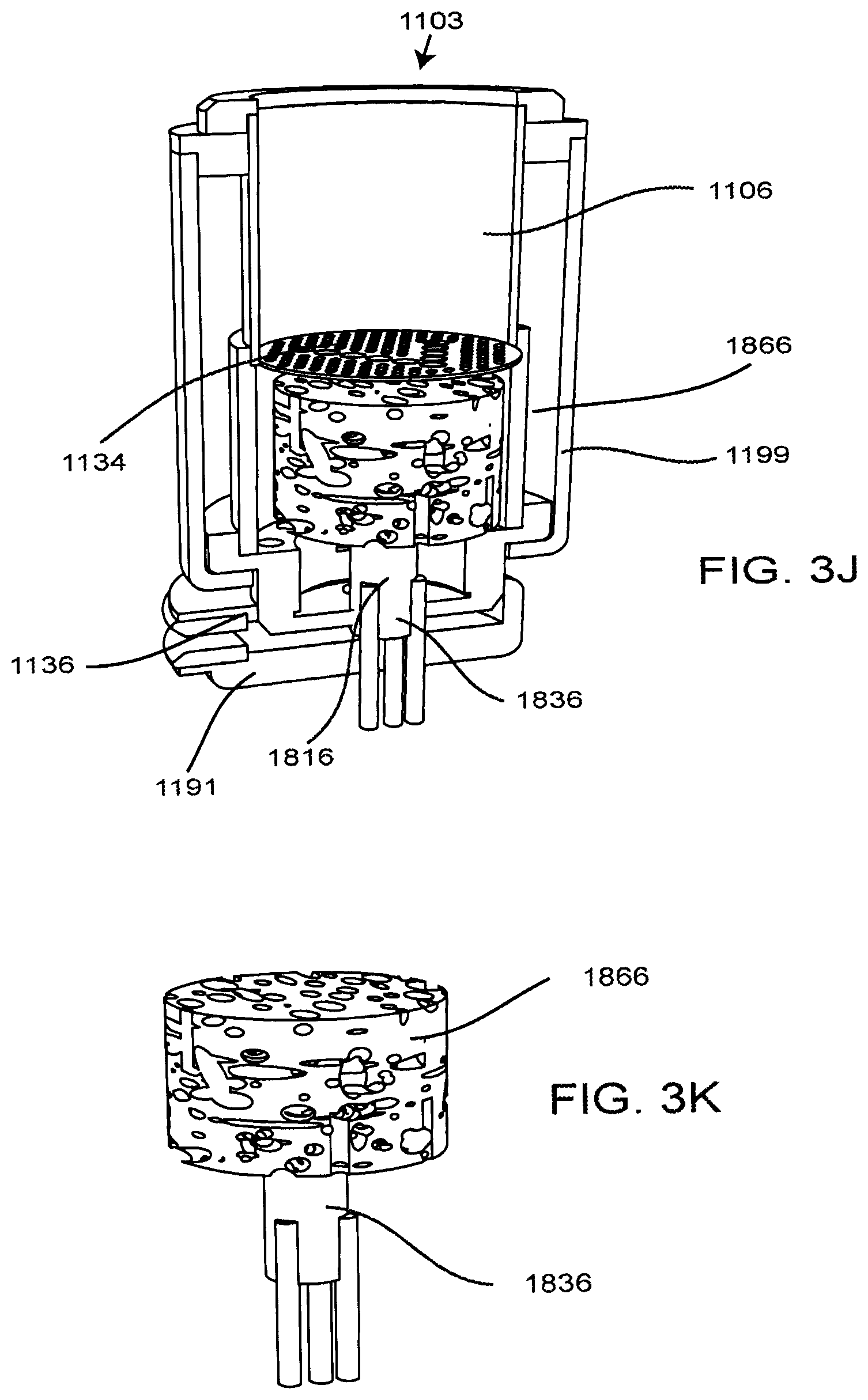
D00020

XML
uspto.report is an independent third-party trademark research tool that is not affiliated, endorsed, or sponsored by the United States Patent and Trademark Office (USPTO) or any other governmental organization. The information provided by uspto.report is based on publicly available data at the time of writing and is intended for informational purposes only.
While we strive to provide accurate and up-to-date information, we do not guarantee the accuracy, completeness, reliability, or suitability of the information displayed on this site. The use of this site is at your own risk. Any reliance you place on such information is therefore strictly at your own risk.
All official trademark data, including owner information, should be verified by visiting the official USPTO website at www.uspto.gov. This site is not intended to replace professional legal advice and should not be used as a substitute for consulting with a legal professional who is knowledgeable about trademark law.