Multi-metallic Electro-catalyst For Alkaline Exchange Membrane Fuel Cells And Method Of Making Same
PASKA; Yair ; et al.
U.S. patent application number 16/636064 was filed with the patent office on 2020-05-21 for multi-metallic electro-catalyst for alkaline exchange membrane fuel cells and method of making same. This patent application is currently assigned to POCELL TECH LTD.. The applicant listed for this patent is POCELL TECH LTD.. Invention is credited to Ben ACHRAI, Charly David AZRA, Anna KITAYEV, Miles PAGE, Yair PASKA.
| Application Number | 20200161686 16/636064 |
| Document ID | / |
| Family ID | 61866866 |
| Filed Date | 2020-05-21 |


| United States Patent Application | 20200161686 |
| Kind Code | A1 |
| PASKA; Yair ; et al. | May 21, 2020 |
MULTI-METALLIC ELECTRO-CATALYST FOR ALKALINE EXCHANGE MEMBRANE FUEL CELLS AND METHOD OF MAKING SAME
Abstract
Some aspects of the invention may be directed to a catalyst layer for anodes of Alkaline Exchange Membrane Fuel Cells (AEMFC). Such catalyst layer may include catalyst nanoparticles and an ionomer. Each catalyst nanoparticle may include one or more nanoparticles of catalytically active metal supported on at least one nanoparticle of crystalline RuO.sub.2. The diameter of the at least one nanoparticle of the crystalline RuO.sub.2 may be about order of magnitude larger than the diameter of the one or more nanoparticles of catalytically active metal.
| Inventors: | PASKA; Yair; (Kiryat Ata, IL) ; PAGE; Miles; (Hod Hasharon, IL) ; AZRA; Charly David; (Netanya, IL) ; ACHRAI; Ben; (Pardes Hanna, IL) ; KITAYEV; Anna; (Rosh Ha Ayin, IL) | ||||||||||
| Applicant: |
|
||||||||||
|---|---|---|---|---|---|---|---|---|---|---|---|
| Assignee: | POCELL TECH LTD. Caesarea IL |
||||||||||
| Family ID: | 61866866 | ||||||||||
| Appl. No.: | 16/636064 | ||||||||||
| Filed: | July 30, 2018 | ||||||||||
| PCT Filed: | July 30, 2018 | ||||||||||
| PCT NO: | PCT/IL2018/050845 | ||||||||||
| 371 Date: | February 3, 2020 |
| Current U.S. Class: | 1/1 |
| Current CPC Class: | H01M 4/92 20130101; H01M 4/921 20130101; H01M 4/9016 20130101; H01M 4/925 20130101; H01M 8/083 20130101; H01M 4/926 20130101; H01M 2008/1095 20130101; H01M 4/8892 20130101; H01M 8/1004 20130101 |
| International Class: | H01M 8/1004 20060101 H01M008/1004; H01M 8/083 20060101 H01M008/083; H01M 4/92 20060101 H01M004/92; H01M 4/90 20060101 H01M004/90; H01M 4/88 20060101 H01M004/88 |
Foreign Application Data
| Date | Code | Application Number |
|---|---|---|
| Aug 3, 2017 | IL | 253814 |
Claims
1. A catalyst layer for anodes of Alkaline Exchange Membrane Fuel Cells (AEMFC), comprising: catalyst nanoparticles, wherein each catalyst nanoparticle comprises: one or more nanoparticles of catalytically active metal supported on at least one nanoparticle of crystalline RuO.sub.2; and an ionomer.
2. A catalyst layer according to claim 1, wherein the diameter of the at least one nanoparticle of a conductive compound is at least one order of magnitude larger than the diameter of the one or more nanoparticles of catalytically active metal.
3. A catalyst layer according to claim 1, wherein the catalytically active metal is selected from a group consisting of: Pt, Pd, Ir, Ru and their alloys.
4. A catalyst layer according to claim 1, wherein each catalyst nanoparticle further comprises one or more catalytically non-active metallic nanoparticles.
5. A catalyst layer according to claim 4, wherein the one or more catalytically non-active metallic nanoparticles is selected from a group consisting of: Ag, Ni, Fe
6. A catalyst layer according to claim 1, wherein the catalyst nanoparticles comprise between 2 wt. % to at most 20 wt. % of the catalytically active metal.
7. A catalyst layer according to claim 1, wherein the size of the catalytically active metal nanoparticles is between 2-10 nm.
8. A catalyst layer according to claim 1, having at thickness of at most 25 micrometer.
9. A catalyst layer according to claim 1, comprising between 5-35 wt. % ionomer.
10. A catalyst layer for anodes of Alkaline Exchange Membrane Fuel (Cells (AEMFC), comprising: catalyst nanoparticles, wherein each catalyst nanoparticle comprises: one or more nanoparticles of catalytically active metal supported on at least one Ru nanoparticle; and an ionomer.
11. A catalyst layer according to claim 10, wherein the catalytically active metal is selected from a group consisting of: Pt, Pd, Ir, and their alloys.
12. A catalyst layer according to claim 10, wherein each catalyst nanoparticle further comprises at least one nanoparticle of a conductive compound.
13. A catalyst layer according to claim 12, wherein the conductive compound is selected from a group consisting of: crystalline RuO.sub.2, crystalline doped TiO.sub.2, crystalline WC and crystalline NbOx.
14. A catalyst layer according to claim 10, wherein the diameter of the at least one Ru nanoparticle is at least one order of magnitude larger than the diameter of the one or more nanoparticles of catalytically active metal.
15. A catalyst layer according to claim 10, wherein the size of the catalytically active metal nanoparticles is between 2-10 nm.
16. A catalyst layer according to claim 10, having at thickness of at most 25 micrometer.
17. A catalyst layer according to claim 10, comprising between 5-35 wt. % ionomer.
18. A catalyst layer for anodes of Alkaline Exchange Membrane Fuel Cells (AEMFC), comprising: catalyst nanoparticles, wherein each catalyst nanoparticle comprises: one or more nanoparticles of catalytically active metal supported on at least one nanoparticle of crystalline TiO.sub.2 or NbOx; and an ionomer.
19. An Alkaline Exchange Membrane Fuel Cell, comprising: an Alkaline Exchange Membrane, a cathode catalyst coated on a first side of the Alkaline Exchange Membrane; and an anode catalyst according to claim 1 coated on a second side of the Alkaline Exchange Membrane.
Description
TECHNICAL FIELD OF THE INVENTION
[0001] The invention is generally related to the field of alkaline exchange membrane fuel cells and more precisely to catalysts for alkaline exchange membrane fuel cells.
BACKGROUND OF THE INVENTION
[0002] Alkaline exchange membrane fuel cells (AEMFC) are usually operated with hydrogen containing fuels having the lowest possible content of CO.sub.2. Research has proved that as little as 5 ppm of CO.sub.2 can harm the performance of the fuel cell. In order to reduce the amount of CO.sub.2 in the cell, complicated and sometime expensive CO.sub.2 filtering systems are added before the fuel entrance to the fuel cell.
[0003] Currently used anode catalysts for AEMFC include mostly Platinum (Pt) nanoparticles which are becoming inefficient when operating with CO.sub.2-containing fuel. The anode H.sub.2 oxidation reaction (HOR) at Pt surfaces using bi-carbonate ions (as explained below in reactions (4) and (5)) is slower (and thus less favored) in comparison to the HOR using pure H.sub.2 (reaction (1)). The concentration of carbonate and/or bi-carbonate ions in the anode therefore increases with time relative to [OH--], and overall cell performance is therefore reduced. This reduces the ability to use cheaper fuels containing CO.sub.2 (such as, reformed Methanol, Ethanol, etc.). The HOR in AEMFC in the presence of pure H.sub.2 is given in reaction (1)
H.sub.2+2OH.sup.-.fwdarw.2H.sub.2O+2e.sup.- (1)
In the presence of CO.sub.2 some of the hydroxide ions (OH.sup.-), coming to the anode through the membrane from the AEMFC cathode reaction, may transform to bi-carbonates ions according to reaction (2) and/or carbonates ions according to reaction (3):
CO.sub.2+OH.sup.-.fwdarw.HCO.sub.3.sup.- (2)
HCO.sub.3.sup.-+OH.sup.-.fwdarw.H.sub.2O+CO.sub.3.sup.2- (3)
[0004] Bi-carbonate and carbonate ions have lower diffusivity than OH.sup.- ion and therefore may travel inside the AEMFC at lower velocity than OH.sup.-, reducing the cell conductivity. Furthermore, bi-carbonate and carbonate ions accumulate at the AEMFC anode, at the expense of OH ions that are required for reaction. (1).
[0005] At such high CO.sub.2 concentration at the anode, in addition to reaction. (1), two additional, alternative and parallel HOR reactions are available using the bi-carbonate and carbonate ions:
H.sub.2+CO.sub.3.sup.2-.fwdarw.H.sub.2O+CO.sub.2+2e.sup.- (4)
H.sub.2+2HCO.sub.3.sup.-.fwdarw.2H.sub.2O+2CO.sub.2+2e.sup.- (5)
[0006] Therefore, electric current may be obtained using the bi-carbonate and carbonate ions according to reactions (4) and (5). However, catalyzing these reactions is more challenging and thus the overall efficiency of the HOR process of reactions (4) and (5) is significantly reduced.
[0007] Therefore, in order to use cheaper fuels and/or reduce the use of filtering there is a need to develop a catalyst that may activate and speed reactions (4) and (5).
SUMMARY OF THE INVENTION
[0008] Some aspects of the invention may be directed to a catalyst layer for anodes of Alkaline Exchange Membrane Fuel Cells (AEMFC). Such catalyst layer may include catalyst nanoparticles and an ionomer. In some embodiments, each catalyst nanoparticle may include one or more nanoparticles of catalytically active metal supported on at least one nanoparticle of a conductive compound, for example, crystalline RuO.sub.2. In some embodiments, the diameter of the at least one nanoparticle of a conductive compound may be about order of magnitude larger than the diameter of the one or more nanoparticles of catalytically active metal.
[0009] In some embodiments, the catalytically active metal may be selected from a group consisting of: Pt, Pd, Ir, Ru and their alloys. In some embodiments, the conductive compound may be selected from a group consisting of: crystalline metal oxides, crystalline RuO.sub.2, crystalline doped TiO.sub.2. In some embodiments, each catalyst nanoparticle further comprises one or more catalytically non-active metallic nanoparticles. In some embodiments, the one or more catalytically non-active metallic nanoparticles may be selected from a group consisting of: Ru, Ag, Ni, Fe.
[0010] In some embodiments, the catalyst nanoparticles may include between 2 wt. % to at most 20 wt. % of the catalytically active metal. In some embodiments, the size of the catalytically active metal nanoparticles is between 2-10 nm. In some embodiments, the catalyst layer may have at thickness of at most 25 micrometer. In some embodiments, the catalyst layer may include between 5-35 wt. % ionomer.
[0011] Some additional aspects of the invention may be directed to a catalyst layer for anodes of Alkaline Exchange Membrane Fuel Cells (AEMFC). This catalyst layer may include catalyst nanoparticles having one or more nanoparticles of catalytically active metal supported on at least one Ru nanoparticle and an ionomer. In some embodiments, the catalytically active metal may be selected from a group consisting of: Pt, Pd, Ir, Ru and their alloys.
[0012] In some embodiments, each catalyst nanoparticle may further include at least one nanoparticle of a conductive compound. In some embodiments, the conductive compound may be selected from a group consisting of: metal oxides, crystalline RuO.sub.2, crystalline doped TiO.sub.2. In some embodiments, the at least one Ru nanoparticle may have a diameter about one order of magnitude larger than the diameter of the one or more nanoparticles of catalytically active metal. In some embodiments, the size of the catalytically active metal nanoparticles may be between 2-10 nm.
[0013] In some embodiments, the size of the catalytically active metal nanoparticles is between 2-10 nm. In some embodiments, the catalyst layer may have at thickness of at most 25 micrometer. In some embodiments, the catalyst layer may include between 5-35 wt. % ionomer.
[0014] Some aspects of the invention may be directed to an Alkaline Exchange Membrane Fuel Cell. The Alkaline Exchange Membrane Fuel Cell may include an Alkaline Exchange Membrane, a cathode catalyst coated on a first side of the Alkaline Exchange Membrane; and an anode catalyst according to some embodiments of the invention.
BRIEF DESCRIPTION OF THE DRAWINGS
[0015] The subject matter regarded as the invention is particularly pointed out and distinctly claimed in the concluding portion of the specification. The invention, however, both as to organization and method of operation, together with objects, features, and advantages thereof, may best be understood by reference to the following detailed description when read with the accompanying drawings in which:
[0016] FIG. 1 is an illustration of an alkaline exchange membrane fuel cell according to some embodiments of the invention;
[0017] FIG. 2 is an illustration of an anode catalyst layer for an alkaline exchange membrane fuel cell according to some embodiments of the invention;
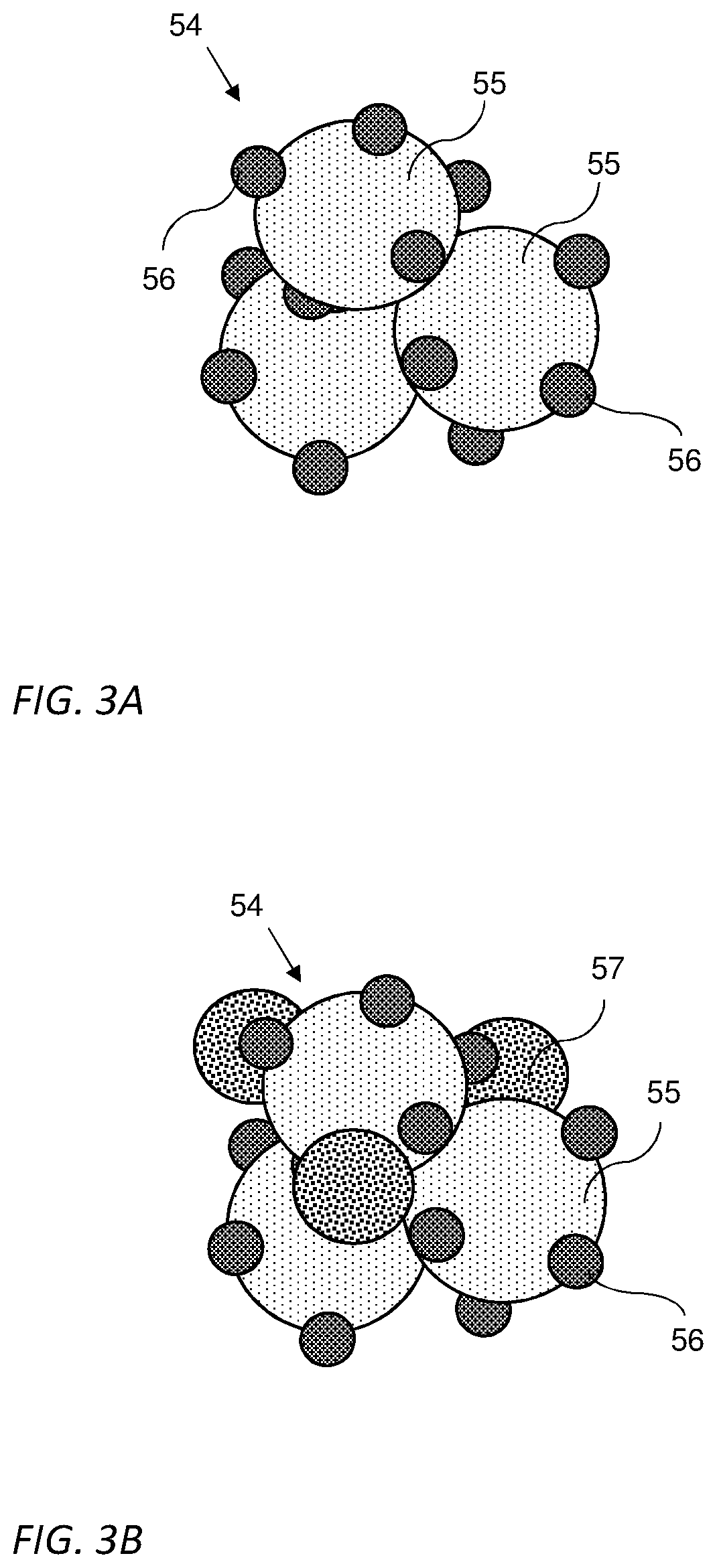
[0018] FIGS. 3A and 3B are illustration of nanoparticles of an anode catalyst for an alkaline exchange membrane fuel cell according to some embodiments of the invention;
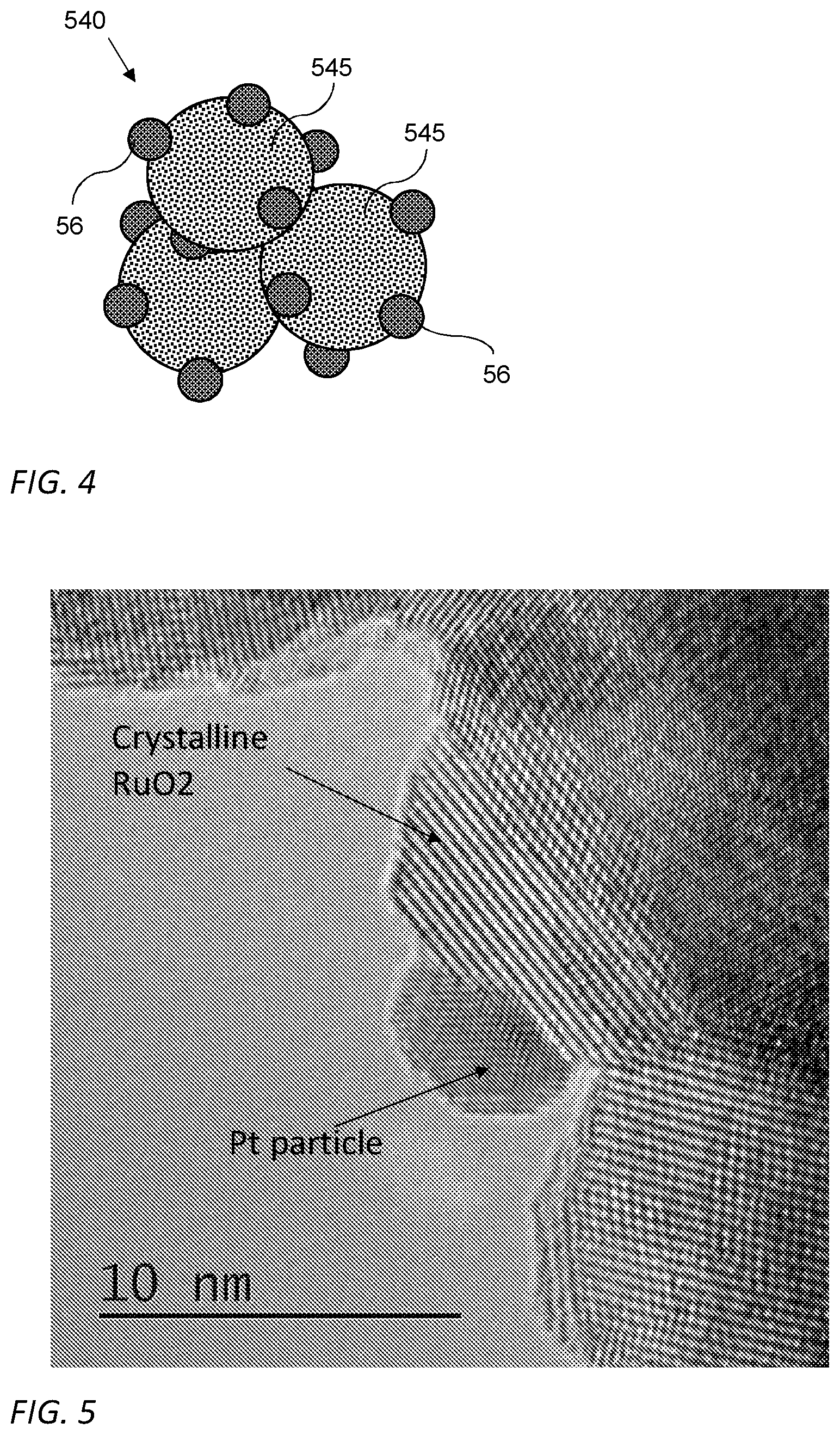
[0019] FIG. 4 is an illustration of a nanoparticle of an anode catalyst for an alkaline exchange membrane fuel cell according to some embodiments of the invention;
[0020] FIG. 5 is a high resolution transmission electron micrograph (lattice image) of a nanoparticle according to some embodiments of the invention;
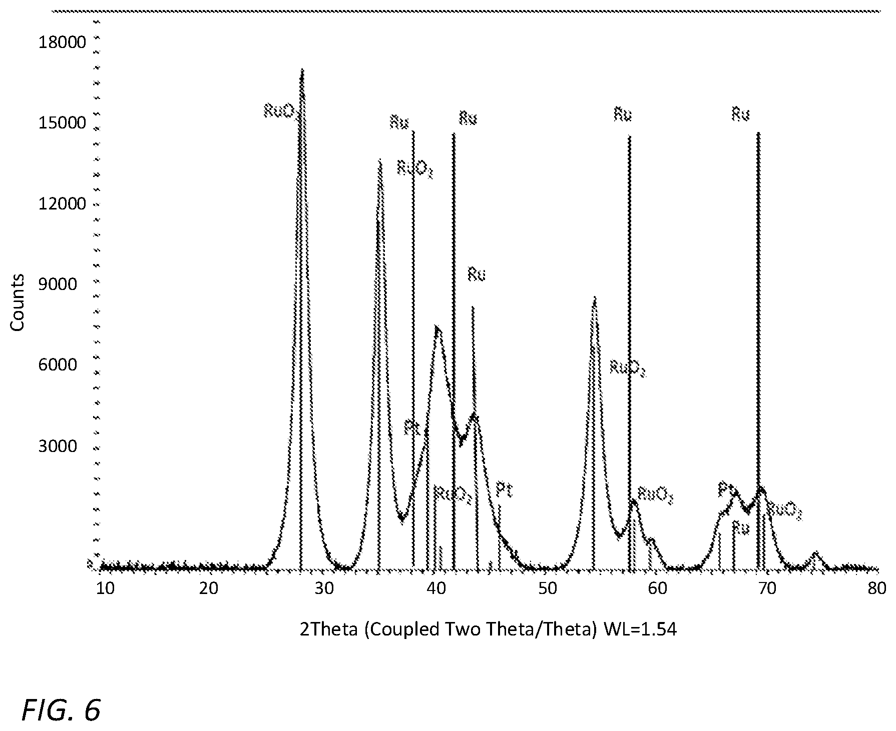
[0021] FIG. 6 is an X-Ray diffraction of a catalyst for an alkaline exchange membrane fuel cell according to some embodiments of the invention;
[0022] FIGS. 7A-7C are graphs of Voltage vs. Current Density of alkaline exchange membrane fuel cells with Pt based anode catalyst and anode catalysts according to some embodiments of the invention;
[0023] FIG. 8 is a graph of the performance over time of alkaline exchange membrane fuel cells having an anode catalyst according to some embodiments of the invention; and
[0024] FIG. 9 is a graph of Voltage vs. Current Density of alkaline exchange membrane fuel cells with Ir based anode catalyst according to some embodiments of the invention.
[0025] It will be appreciated that for simplicity and clarity of illustration, elements shown in the figures have not necessarily been drawn to scale. For example, the dimensions of some of the elements may be exaggerated relative to other elements for clarity. Further, where considered appropriate, reference numerals may be repeated among the figures to indicate corresponding or analogous elements.
DETAILED DESCRIPTION OF THE PRESENT INVENTION
[0026] In the following detailed description, numerous specific details are set forth in order to provide a thorough understanding of the invention. However, it will be understood by those skilled in the art that the present invention may be practiced without these specific details. In other instances, well-known methods, procedures, and components have not been described in detail so as not to obscure the present invention.
[0027] Some aspects of the invention may be related to increasing the ability to use cheaper fuels containing CO.sub.2 (such as reformed Methanol, Ethanol, etc.) in Alkaline Exchange Membrane Fuel Cells (AEMFC). In order to do so, special catalysts have been developed. Such catalysts may enable to produce electrical current using reactions (4) and (5) disclosed above. In some embodiments, the newly developed catalysts may further enhance reaction (1), thus improving the overall performance of the AEMFC.
[0028] A catalytic layer for AEMFC may have to exhibit the following properties and performances. For a commercial cost-effective catalytic layer, one may like to minimize the amount of platinum group metals (PGM) due to their high costs. Furthermore, the catalyst layer may have to create electronic percolation using high electrical conducting material. In some embodiments the catalytic layer thickness may be selected as to avoid mass transport issues and keep low overall resistance. Materials selected to be included in the catalyst layer may be as little hydrophobic as possible in order to allow proper water transport. The catalytic layer may further include a sufficient amount of ionomer to allow ion and water transport and a sufficient amount of porosity to allow gas penetration. Accordingly, such catalyst layer may include a conductive hydrophilic support particles to support the minimal amount of costly active material (e.g., PGM) required.
[0029] The commonly used carbon particles support is highly hydrophobic and has low tap density that may make the catalyst layer too thick.
[0030] A catalyst according to some embodiments of the invention may include catalyst nanoparticles, in which each catalyst nanoparticle may include at least two different types of nanocrystals: catalytically active metallic nanocrystals supported, attached and/or carried on larger electrically conducting compound nanocrystals. As used herein catalytically active metallic nanocrystals may include metallic nanocrystals that catalytically activate the chemical reactions taking place on the surface of the anode and the cathode of the AEMFC, for example, reactions (1)-(5) disclosed herein above. In some embodiments, the electrically conducting nanocrystals may be configured to increase the surface area of the catalytically active metallic nanocrystals. In some embodiments, the catalyst may further include an ionomer holding the catalyst nanoparticle as a layer. The ionomer may be crosslinked or may not be crosslinked to the anion conducting membrane.
[0031] Reference is now made to FIG. 1 which is an illustration of an AEMFC according to some embodiments of the invention. An AEMFC 10 may include an anion conducting membrane 20 a cathode catalyst layer 30 coated on the cathode side of membrane 20, a cathode gas diffusion layer (GDL) 40, an anode catalyst layer 50 coated or attached to the anode side of membrane 20 and anode GDL 60. Anion conducting membrane 20 may be any membrane configured to conduct anions such as OH.sup.-, CO.sub.3.sup.2- and HCO.sub.3.sup.-. In some embodiments, membrane 20 may include anions conducting solid polymer electrolyte that includes hydrocarbon backbone polymer, for example, Tokuyama AS4.TM., Fumatech FAA-3.TM., or aminated Poly Chloromethyl Styrene (also known as Poly Vinyl Benzyl Chloride) and the like.
[0032] Cathode catalyst layer 30 may include any suitable cathode catalyst metal, such as Ag with any suitable additives such as carbon, ionomer, etc.
[0033] GDLs 40 and 60 may include porous material made from a dense array of carbon fibers (base e.g., on carbon paper, carbon cloth, carbon fiber or the like, with or without a micro porous layer (MPL). These GDLs may also provide an electrically conductive pathway for current collection. In some embodiments, GDLs 40 and 60 may allow passage for reactant transport and heat/water removal. GDLs 40 and 60 may further provide mechanical support to membrane 20 and protection of catalyst layers 30 and 50 from corrosion or erosion caused by flows or other factors.
[0034] Reference is now made to FIG. 2 which is an illustration of anode catalyst layer 50 according to some embodiments of the invention. Anode catalyst layer 50 may include catalyst nanoparticles 54 and an ionomer 58. Ionomer 58 may include any ionomer suitable for carrying a catalyst in an AEMFC. For example, ionomer 58 may include Tokuyama AS4, Fumatech FAA-3, or aminated Poly Chloromethyl Styrene (also known as Poly Vinyl Benzyl Chloride) and the like. Materials selected to be included in catalyst layer 50 may be as little hydrophobic as possible in order to allow proper water transport. Catalytic layer 50 may include a sufficient amount of ionomer 85 to allow ion and water transport and a sufficient amount of porosity to allow gas penetration. In some embodiments, catalyst layer 50 may include between 5-35 wt. % ionomer. In some embodiments, catalyst layer 50 may have a thickness of at most 25 micrometer.
[0035] Reference is now made to FIGS. 3A and 3B which are illustrations of a catalyst nanoparticle 54 according to some embodiments of the invention. Catalyst nanoparticle 54 may include one or more nanoparticles 56 of catalytically active metal supported, carried and/or attached to at least one nanoparticle 55 of a conductive compound, as illustrated in FIG. 3A. In some embodiments, catalytically active metal nanoparticles 56 may have a diameter of at least one order of magnitude smaller than conductive compound nanoparticle 55 diameter. In some embodiments, each one of conductive compound nanoparticle 55 and catalytically active metal nanoparticles 56 may be either crystalline of non-crystalline. For example, the size (e.g., average diameter) of catalytically active metal nanoparticles 55 may be between 2-10 nm and the size (e.g., average diameter) of conductive compound nanoparticles 56 may be between 20-100 nm.
[0036] In some embodiments, the catalytically active metal may be selected from a group consisting of: PGM, such as, Pt, Pd, Ir and their alloys. In some embodiments, catalytically active metal nanoparticles 55 may include a nanocrystal of the catalytically active metal. In some embodiments, the conductive compound may be selected to be as little hydrophobic as possible, as explained above. In some embodiments, the conductive compound may be selected from a group consisting of: crystalline metal oxides such as, crystalline RuO.sub.2, crystalline doped TiO, Nb.sub.xO.sub.y, crystalline metal carbides, such as WC and the like. As used herein crystalline RuO.sub.2 may include nano crystals of RuO.sub.2 that may or may not include doping. In some embodiments, conductive compound nanoparticles 56 may include a nanocrystal of the conductive compound.
[0037] In some embodiments, the catalyst nanoparticle 54 may further include one or more catalytically non-active metallic nanoparticles 57, as illustrated in FIG. 3B. In some embodiments, one or more catalytically non-active metallic nanoparticles 57 may be selected from a group consisting of: Ru, Ag, Ni, Fe nanoparticles. In some embodiments, one or more of catalytically non-active metallic nanoparticles 57 may be a nanocrystal. In some embodiments, the size of catalytically non-active metallic nanoparticle 57 may be between 10-50 nm, between 10-100 nm or more than 100 nm.
[0038] Some aspects of the invention may be related to a catalyst layer for anodes of Alkaline Exchange Membrane Fuel Cells (AEMFC), such as layer 50, that include catalyst nanoparticles 540 (illustrated in FIG. 4) and an ionomer, such as the ionomer 58 illustrated and discussed with respect to FIG. 2. Reference is now made to FIG. 4 which is an illustration of catalyst nanoparticle 540 that may include one or more nanoparticles 56 of catalytically active metal supported, carried and/or attached on at least one Ru nanoparticle 545. Catalytically active nanoparticles 56 included in nanoparticles 540 may be substantially the same as nanoparticles 56 included in catalyst nanoparticles 54. In some embodiments, Ru nanoparticle 545 may be crystalline. In some embodiments, the size (e.g., average diameter) of Ru nanoparticle 545 may be at least one order of magnitude larger than catalytically active nanoparticles 56.
Experimental Results
[0039] Catalysts nanoparticles were prepared using any known method. For example, the catalyst nanoparticles may be prepared by reduction of a salt of the required metal(s), e.g. RuCl.sub.3.xH.sub.2O or similar, by the use of a suitable reducing agent such as sodium acetate, sodium or other borohydride, hydrazine, or any number of other available known reducing agents. For example, the precursor materials may be held in aqueous solution and heated under reflux conditions or hydrothermal conditions, or by heating by microwave or other direct radiation. In these examples, depending on the process chosen, the metal salt and the reducing agent can be pre-mixed or mixed after heating to a desired temperature. Blending of the reducing agent with the metal salt, possibly with additional treatment such as heating, may lead to the formation of nucleated metal clusters that develop with time into nanoparticles in the reaction mixture. The growth of these particles may be controlled by reaction time, temperature, and in some cases the presence of surface-active agents (surfactants) or other additives to moderate growth of the particles.
[0040] Once the reaction have been proceeded to completion (yielding nanoparticles of the desired size, morphology etc.), the reaction mixture may be removed from the reaction conditions (e.g., cooled to room temperature and/or pressure) and the supernatant then separated from the particles. Additives and remaining reactants may be subsequently washed and/or burned away. Exposure to oxygen during the process may lead to the formation of metal oxide(s) together with or in place of, or as a part of, the metal particles. This can also typically be controlled to a certain degree.
[0041] Another example for a method of preparing catalyst nanoparticles may include: depositing catalytic nanoparticles on the support particles by following a similar procedure but using a salt of the catalytic metal(s), with the same or different combinations of reducing agent(s) and surfactant(s), in the presence of pre-formed support particles.
[0042] In yet another example, the catalytic particles may be prepared separately and later mixed mechanically by various means known in the art such as stirring, sonication and/or other homogenizing techniques applied to a co-dispersion, and/or by ball milling or other processing techniques. Alternatively, the two types of particles may be prepared in a single step where salts of both metals are present in the reaction mixture. Such a one-step process (mixing the salts of different metals together) could lead either to alloys of the various particles, separate particles of one species and another, or a mixture of those.
[0043] The catalyst nanoparticles included: 15 weight (wt.)% Pt, 42.5 wt. % RuO2 and 42.5 wt. % Ru or 9 wt. % Pt, 45.5 wt. % RuO2 and 45.5 wt. % Ru. The catalysts nanoparticles were analyzed using HRTEM and XRD and added to an ionomer to form a catalytic layer of a solid electrolyte membrane. The performance of the new catalytic layer were tested during the operation of an AEMFC.
[0044] Reference is now made to FIG. 5 which is a lattice image taken by a high resolution transmission electron microscope of a catalyst nanoparticle according to some embodiments of the invention. The image shows a small Pt crystal having a diameter of approximately 5 nm attached to a larger RuO.sub.2 crystal having a dimeter of approximately 10 nm.
[0045] Reference is now made to FIG. 6 which is an XRD spectrum taken from the catalyst according to some embodiments of the invention. The XRD maxima were identified as the typical maxima of crystalline Pt, Ru and RuO.sub.2.
[0046] The performance of the new catalyst was tested and compared to known catalyst made from Pt nanoparticles. FIG. 7A shows graphs showing the voltage vs. the current density taken from an AEMFC that included the Pt anode catalyst when supplied with two types of fuels: a clean H.sub.2 having less than 1 ppm CO.sub.2 and H.sub.2 with 100 ppm CO.sub.2. As can clearly be seen, there is a loss of more than 10% in the voltage at high current densities (above 0.6 A/cm.sup.3) when operating the cell with H.sub.2 with 100 ppm CO.sub.2.
[0047] FIG. 7B shows graphs showing the voltage vs. the current density taken from an AEMFC that included an anode catalyst according to some embodiments of the invention. The catalyst of FIG. 7B included 15 wt. % Pt, 42.5 wt. % RuO.sub.2 and 42.5 wt. % Ru. As can clearly be seen less than 10% (approximately 7%) loss in the voltage at high current densities (above 0.6 A/cm.sup.3) when operating the cell with H.sub.2 with 100 ppm CO.sub.2 has been achieved.
[0048] FIG. 7C shows graphs showing the voltage vs. the current density taken from an AEMFC that included an anode catalyst according to some embodiments of the invention. The catalyst of FIG. 7C included 9 wt. % Pt, 45.5 wt. % RuO.sub.2 and 45.5 wt. % Ru. As can clearly be seen there is no losses at all when operating the cell with the new catalysts. Furthermore, the overall drop in voltage at higher current densities of the cell operating in both types of fuels is 20% less than the drop in the fuel cell of FIG. 7A operating with pure H.sub.2. Accordingly, a catalysts made according to embodiments of the invention may improve the performance of the fuel cell operating which any type of fuel in comparison to fuel cells known in the art.
[0049] FIG. 8 shows the performance (in percentage; voltage, current or power) over time of a cell with a catalyst according to embodiments of the invention (the catalyst of FIG. 7B) operating with fuels having 100 ppm and 1 ppm levels of CO.sub.2 at the anode fuel stream. As can clearly be seen the performance drops by approximately 9% over time when operating the fuel cell with fuel having 100 ppm of CO.sub.2.
[0050] FIG. 9 shows graphs showing the voltage vs. the current density taken from an AEMFC that included an anode catalyst according to some embodiments of the invention. The catalyst of FIG. 9 included Ir, RuO.sub.2 and Ru. As can clearly be seen there is no loses at all when operating the cell with the new catalysts with both fuel types having 1 and 100 ppm of CO.sub.2. Accordingly, an Ir based catalyst made according to embodiments of the invention may improve the performance of the fuel cell operating which any type of fuel in comparison to fuel cells known in the art.
[0051] While certain features of the invention have been illustrated and described herein, many modifications, substitutions, changes, and equivalents will now occur to those of ordinary skill in the art. It is, therefore, to be understood that the appended claims are intended to cover all such modifications and changes as fall within the true spirit of the invention.
* * * * *
D00000
D00001
D00002
D00003
D00004
D00005
D00006
D00007
XML
uspto.report is an independent third-party trademark research tool that is not affiliated, endorsed, or sponsored by the United States Patent and Trademark Office (USPTO) or any other governmental organization. The information provided by uspto.report is based on publicly available data at the time of writing and is intended for informational purposes only.
While we strive to provide accurate and up-to-date information, we do not guarantee the accuracy, completeness, reliability, or suitability of the information displayed on this site. The use of this site is at your own risk. Any reliance you place on such information is therefore strictly at your own risk.
All official trademark data, including owner information, should be verified by visiting the official USPTO website at www.uspto.gov. This site is not intended to replace professional legal advice and should not be used as a substitute for consulting with a legal professional who is knowledgeable about trademark law.