System And Method For Processing Multi-directional Ultra Wide Band Wireless Backscattered Signals
JOSHI; Kiran R. ; et al.
U.S. patent application number 16/194155 was filed with the patent office on 2020-05-21 for system and method for processing multi-directional ultra wide band wireless backscattered signals. The applicant listed for this patent is Totemic Labs, Inc.. Invention is credited to Kiran R. JOSHI, Lenin PATRA.
| Application Number | 20200158819 16/194155 |
| Document ID | / |
| Family ID | 70727697 |
| Filed Date | 2020-05-21 |


View All Diagrams
| United States Patent Application | 20200158819 |
| Kind Code | A1 |
| JOSHI; Kiran R. ; et al. | May 21, 2020 |
SYSTEM AND METHOD FOR PROCESSING MULTI-DIRECTIONAL ULTRA WIDE BAND WIRELESS BACKSCATTERED SIGNALS
Abstract
An ultra-wide band rf sensing apparatus or module. In an example, the apparatus has at least three antenna arrays configured to sense a back scatter of electromagnetic energy from spatial location of a zero degree location in relation to a mid point of the device through a 360 degrees range where each antenna array is configured to sense a 120 degree range. As shown, each of the three antenna arrays comprises a support member, a plurality of transmitting antenna spatially configured on a first portion of the support member. The support member also has a transmitting integrated circuit coupled to each of the plurality of transmitting antenna and configured to transmit an outgoing UWC signal. Each of the antenna array also has a plurality of receiving antenna spatially configured on second portion of the support member. The support member also has a receiving integrated circuit coupled to each of the plurality of receiving antenna and configured to receive an incoming UWB signal and configured to convert the UWC signal into a base band.
| Inventors: | JOSHI; Kiran R.; (Palo Alto, CA) ; PATRA; Lenin; (Palo Alto, CA) | ||||||||||
| Applicant: |
|
||||||||||
|---|---|---|---|---|---|---|---|---|---|---|---|
| Family ID: | 70727697 | ||||||||||
| Appl. No.: | 16/194155 | ||||||||||
| Filed: | November 16, 2018 |
| Current U.S. Class: | 1/1 |
| Current CPC Class: | G06N 3/04 20130101; G01S 13/0209 20130101; G01S 13/42 20130101; G01S 13/886 20130101; G06N 3/08 20130101; G01P 13/00 20130101; G01S 13/583 20130101; G01S 7/352 20130101 |
| International Class: | G01S 7/35 20060101 G01S007/35; G01S 13/58 20060101 G01S013/58; G01P 13/00 20060101 G01P013/00; G01S 13/02 20060101 G01S013/02; G06N 3/04 20060101 G06N003/04 |
Claims
1. An ultra-wide band rf sensing apparatus comprising: at least three antenna arrays configured to sense a back scatter of electromagnetic energy from spatial location of a zero degree location in relation to a mid point of the device through a 360 degrees range where each antenna array is configured to sense a 120 degree range; each of the three antenna arrays comprising: a support member; a plurality of transmitting antenna spatially configured on a first portion of the support member; a transmitting integrated circuit coupled to each of the plurality of transmitting antenna and configured to transmit an outgoing UWC signal; a plurality of receiving antenna spatially configured on second portion of the support member; a receiving integrated circuit coupled to each of the plurality of receiving antenna and configured to receive an incoming UWB signal and configured to convert the UWC signal into a base band; a triangular configuration comprising a first antenna array, a second antenna array, and a third antenna array included in the at least three antenna arrays to provide a 360 degree visibility range as measured from a horizontal plane, and a 80 degree visibility range as measured from a vertical plane normal to the horizontal plane; and a housing enclosing the at least three antenna array.
2. The apparatus of claim 1 wherein the UWC module comprises a switch configured between a plurality of UWC transceivers, such that the switch is configured to select one of the three antenna arrays to sense the back scatters while the other two antenna arrays are turned off.
3. The apparatus of claim 2 further comprising a controller configured to control the switch and the three antenna array, the controller cycles through a predetermined process to decide which one of the three antenna array to activate while the other two antenna arrays are turned off.
4. The apparatus of claim 2 wherein the at least three antenna array are configured to sense electromagnetic energy ranging from 6 to 8 GHz in frequency.
5. The apparatus of claim 2 wherein the sensing apparatus is spatially positioned within a center of a geographic location of a room to detect movement of human user.
6. The apparatus of claim 1 wherein each of the sensor arrays is provided on a substrate member to be configured in the triangular configuration, the substrate member having a face arranged in a normal manner in a direction to each of the support members.
7. The apparatus of claim 1 wherein the housing is characterized by a mechanical structure to enclose the ultra-wide band sensing apparatus.
8. The apparatus of claim 1 further comprising: a housing having a maximum length of six to twenty four inches and width of no longer than six inches, the housing having sufficient structural strength to stand upright and protect an interior region within the housing; a height characterizing the housing from a bottom region to a top region; a plurality of levels within the housing numbered from 1 to N, wherein N is an integer greater than two; a speaker device configured within the housing and over the bottom region; a compute module comprising a processing device over the speaker device; an artificial intelligence module configured over the compute module; an ultra-wide band ("UWB") module configured overlying the artificial intelligence module, the UWB module comprising the three antenna arrays and the triangular configuration; a frequency modulated continuous wave ("FMCW") module with an antenna array configured over the UWC module, the FMCW module being configured to process electromagnetic radiation in a frequency range of 24 GHz to 24.25 GHz; an audio module configured over the FMWC module; and an inertial measurement unit ("IMU") module configured over the FMCW module.
9. The device of claim 8 wherein the speaker device, the compute module, the artificial intelligence module, the UWB module, the FMCW module, the audio module, and the IMU module are arranged in a stacked configuration and configured, respectively, in the plurality of levels numbered from 1 to N; and wherein the speaker device comprises an audio output configured to be included in the housing, the speaker device being configured to output energy within a 360 degree range from a midpoint of the device; and wherein the compute module comprises a microprocessor based unit coupled to a bus, the compute module comprises a signal processing core, a micro processor core for an operating system, a synchronizing processing core configured to time stamp, and synchronize incoming information from each of the FMCW module, IMU module, and UWB module.
10. The device of claim 8 further comprising: a real time processing unit configured to control the FMCW switch or the UWB switch or other switch requiring a real time switching operation of less than 1/2 milliseconds of receiving feedback from a plurality of sensors; a graphical processing unit configured to process information from the artificial intelligence module. wherein the artificial intelligence module comprises an artificial intelligence inference accelerator configured to apply a trained module using a neural net based process, the neural net based process comprising a plurality of nodes numbered form 1 through N; wherein the audio module comprises a micro phone array for detecting energy in a frequency range of sound for communication and for detecting a sound energy; wherein the IMU module comprises at least one motion detection sensor consisting of one of an a gyroscope, an accelerometer, a magnetic sensor, or other motion sensor.
11. A wireless processing apparatus for detecting activities, the device comprising: a housing having a maximum length of six to twenty four inches and width of no longer than ten inches, the housing having sufficient structural strength to stand upright and protect an interior region within the housing; a height characterizing the housing from a bottom region to a top region; a plurality of levels within the housing numbered from 1 to N, where N is an integer greater than 2; a speaker device configured within the housing and overlying the bottom region; a compute module comprising a processing device overlying the speaker device; an audio module coupled to the compute module, the audio module having a micro phone to receive an audio signal from a human user within a vicinity of the apparatus; a ultra-wide band ("UWB") module comprising an antenna array coupled to the compute module, the antenna array configured to sense a back scatter of electromagnetic energy from spatial location of a zero degree location in relation to a mid point of the device through a predetermined angle range, the back scatter of electromagnetic energy being caused by the human user within a vicinity of the apparatus, the antenna array comprising; a support member; a plurality of transmitting antenna spatially configured on a first portion of the support member to transmit an outgoing UWB signal; a transmitting integrated circuit coupled to each of the plurality of transmitting antenna and configured to generate the outgoing UWB signal; a plurality of receiving antenna spatially configured on second portion of the support member to receive the back scattered of the electro magnetic signal derived from the outgoing UWB signal; a receiving integrated circuit coupled to each of the plurality of receiving antenna and configured to receive an incoming UWB signal from the back scattered electro magnetic signal and configured to convert the UWB signal into a base band signal; and an artificial intelligence module configured over the compute module to process information from the incoming UWB signal to provide an output to detect an activity of a human entity.
12. The apparatus of claim 11 wherein the UWB module comprises a micro controller unit coupled to a memory resource, and a clock circuit, the micro controller unit being configured with a universal serial bus interface coupled to the compute module; wherein the compute module is configured with the artificial intelligence module to process information from the back scattered electro magnetic signal from the base band signal to detect the activity of the human entity.
13. The apparatus of claim 11 wherein the support member comprises a major plane positioned normal to a direction of gravity.
14. The apparatus of claim 11 wherein the antenna array comprises at least three antenna array spatially arranged in a triangular configuration comprising a first antenna array, a second antenna array, and a third antenna array included in the at least three antenna arrays to provide a 360 degree visibility range as measured from a horizontal plane, and a 80 degree visibility range as measured from a vertical plane normal to the horizontal plane.
15. The apparatus of claim 11 wherein the antenna array comprises at least three antenna array spatially arranged in a triangular configuration comprising a first antenna array, a second antenna array, and a third antenna array included in the at least three antenna arrays to provide a 360 degree visibility range as measured from a horizontal plane, and a 80 degree visibility range as measured from a vertical plane normal to the horizontal plane, and further comprising a controller configured to control a switch coupled with each of the three antenna array, the controller cycles through a predetermined process to decide which one of the three antenna array to activate while the other two antenna arrays are turned off.
16. The apparatus of claim 11 wherein each antenna array comprises 1-TX and 4-RX.
17. The apparatus of claim 11 further comprising a switch device coupled between each of the antenna array and four receive lanes each of which is coupled to the receiving integrated circuit device; and one transmit lane coupled to a transmitting integrated circuit device.
18. The apparatus of claim 11 further comprising a switch device coupled between each of the antenna array and four receive lanes each of which is coupled to the receiving integrated circuit device; and one transmit lane coupled to a transmitting integrated circuit device; and a micro controller unit coupled to a bus coupled to the receiving integrated circuit device and the transmitting integrated circuit device, the micro controller unit coupled to a memory resource configured with the micro controller to store raw data from information derived from four receive lanes, the micro controller unit being coupled to a clock.
19. The apparatus of claim 11 wherein each antenna array comprises 1 TX and four RX; and further comprising a switch device coupled between each of the three antenna arrays and four receive lanes each of which is coupled to the receiving integrated circuit device; and one transmit lane coupled to a transmitting integrated circuit device; and a micro controller unit coupled to a bus coupled to the receiving integrated circuit device and the transmitting integrated circuit device, the micro controller unit coupled to a memory resource configured with the micro controller to store raw data from information derived from four receive lanes, the micro controller unit being coupled to a clock.
20. A method processing an electromagnetic signal generated from an ultra wide band rf signal to detect an activity of a human user, the method comprising: generating a base band outgoing UWC signal; receiving the base band outgoing UWC signal at a switch device and directing the outgoing UWC signal using the switch device to one of three antenna arrays configured in a triangular configuration to transmit the outgoing UWC signal from spatial location of a zero degree location in relation to a mid point of the device through a 360 degrees visibility range where each antenna array is configured to sense a 120 degree range in a horizontal plane, and each of the antenna array configured to sense and transmit at least an 80 degree visibility range as measured from a vertical plane that is normal to the horizontal plane; each of the three antenna arrays comprising: a support member; a plurality of transmitting antenna spatially configured on a first portion of the support member; a transmitting integrated circuit coupled to each of the plurality of transmitting antenna and configured to transmit the outgoing UWC signal; a plurality of receiving antenna spatially configured on second portion of the support member; a receiving integrated circuit coupled to each of the plurality of receiving antenna and configured to receive an incoming UWB signal and configured to convert the UWC signal into a base band; receiving a back scattered electromagnetic signal caused by an activity of a human user redirecting the outgoing UWB signal.
Description
CROSS-REFERENCE TO RELATED APPLICATIONS
[0001] The present application is related to U.S. Ser. No. 16/103,829, filed on Aug. 14, 2018, which is hereby incorporated by reference in its entirety.
BACKGROUND
[0002] The present invention relates to techniques, including a method, and system, for processing ultra-wide band signals using a plurality of antenna array. In an example, the plurality of antenna array, including a receiving antenna array and a transmitting antenna array configured to capture and transmit signals in an omni-directional manner. Merely by way of examples, various applications can include daily life, and others.
[0003] Various conventional techniques exist for monitoring people within a home or building environment. Such techniques include use of cameras to view a person. Other techniques include a pendant or other sensing device that is placed on the person to monitor his/her movement. Examples include Personal Emergency Response Systems (PERS) devices such as LifeAlert.RTM. and Philips.RTM. LifeLine--each of which are just panic buttons for seniors to press in case of an emergency. Unfortunately, all of these techniques have limitations. That is, each of these techniques fails to provide a reliable and high quality signal to accurately detect a fall or other life activity of the person being monitored. Many people often forget to wear the pendant or a power source for the pendant runs out. Also, elderly people do not want to look like they are old so often times, elderly people do not wear the pendant.
[0004] From the above, it is seen that techniques for identifying and monitoring a person is highly desirable.
SUMMARY
[0005] According to the present invention, techniques related to a method, and system, for processing ultra-wide band signals using a plurality of antenna array are provided. In an example, the plurality of antenna array, including a receiving antenna array and a transmitting antenna array configured to capture and transmit signals in an omni-directional manner. Merely by way of examples, various applications can include daily life, and others.
[0006] The present invention provides a ultra-wide band rf sensing apparatus or module. In an example, the apparatus has at least three antenna arrays configured to sense a back scatter of electromagnetic energy from spatial location of a zero degree location in relation to a mid point of the device through a 360 degrees range where each antenna array is configured to sense a 120 degree range. As shown, each of the three antenna arrays comprises a support member, a plurality of transmitting antenna spatially configured on a first portion of the support member. The support member also has a transmitting integrated circuit coupled to each of the plurality of transmitting antenna and configured to transmit an outgoing UWC signal. Each of the antenna array also has a plurality of receiving antenna spatially configured on second portion of the support member. The support member also has a receiving integrated circuit coupled to each of the plurality of receiving antenna and configured to receive an incoming UWB signal and configured to convert the UWC signal into a base band.
[0007] In an example, the device has a triangular configuration comprising a first antenna array, a second antenna array, and a third antenna array included in the at least three antenna arrays. The three arrays provide a 360 degree visibility range as measured from a horizontal plane, and a 80 degree visibility range as measured from a vertical plane normal to the horizontal plane. As previously noted, the three arrays are enclosed in a housing that provides mechanical support. In an example, each of the sensor arrays is provided on a substrate member to be configured in the triangular configuration. The substrate member has a face arranged in a normal manner in a direction to each of the support members.
[0008] The above examples and implementations are not necessarily inclusive or exclusive of each other and may be combined in any manner that is non-conflicting and otherwise possible, whether they be presented in association with a same, or a different, embodiment or example or implementation. The description of one embodiment or implementation is not intended to be limiting with respect to other embodiments and/or implementations. Also, any one or more function, step, operation, or technique described elsewhere in this specification may, in alternative implementations, be combined with any one or more function, step, operation, or technique described in the summary. Thus, the above examples implementations are illustrative, rather than limiting.
BRIEF DESCRIPTION OF THE DRAWINGS
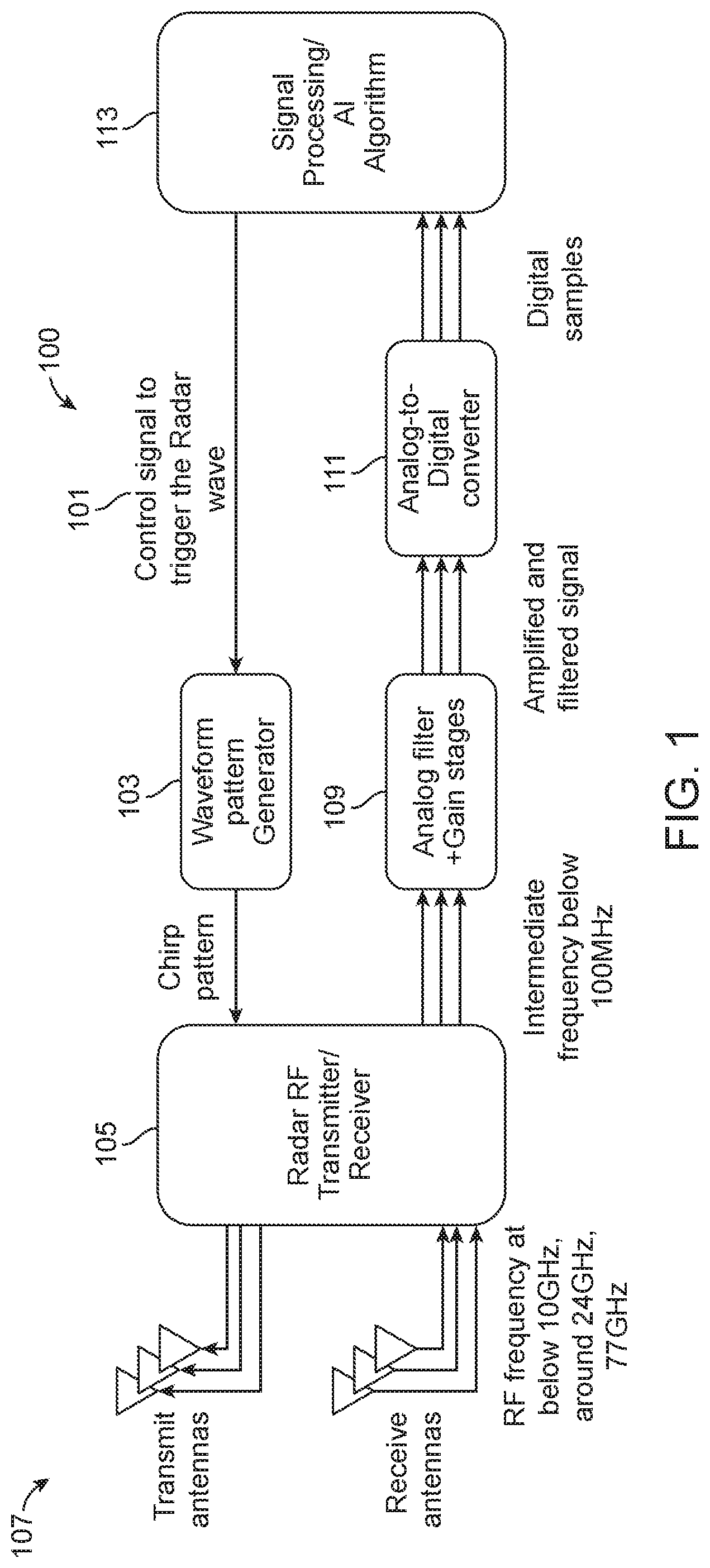
[0009] FIG. 1 is a simplified diagram of a radar/wireless backscattering sensor system according to an example of the present invention.
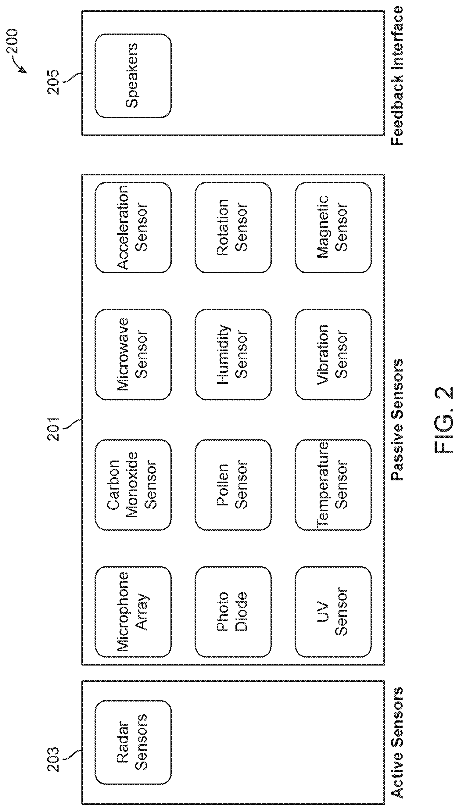
[0010] FIG. 2 is a simplified diagram of a sensor array according to an example of the present invention.
[0011] FIG. 3 is a simplified diagram of a system according to an example of the present invention.
[0012] FIG. 4 is a detailed diagram of hardware apparatus according to an example of the present invention.
[0013] FIG. 5 is a simplified diagram of a hub in a spatial region according to an example of the present invention.
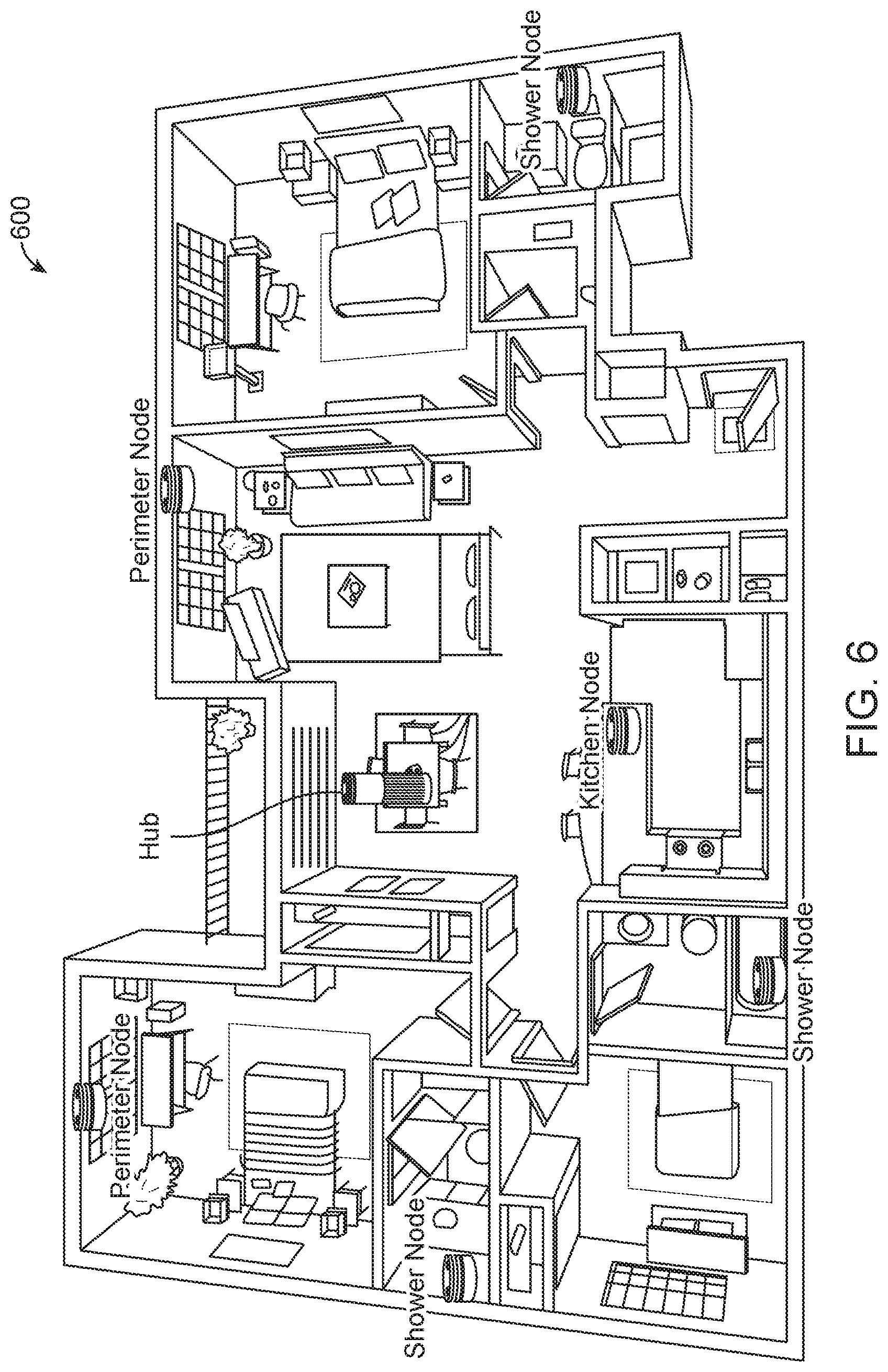
[0014] FIG. 6 is a simplified diagram of a mini mode in a spatial region according to an example of the present invention.
[0015] FIG. 7 is a simplified diagram of a mobile mode in a spatial region according to an example of the present invention.
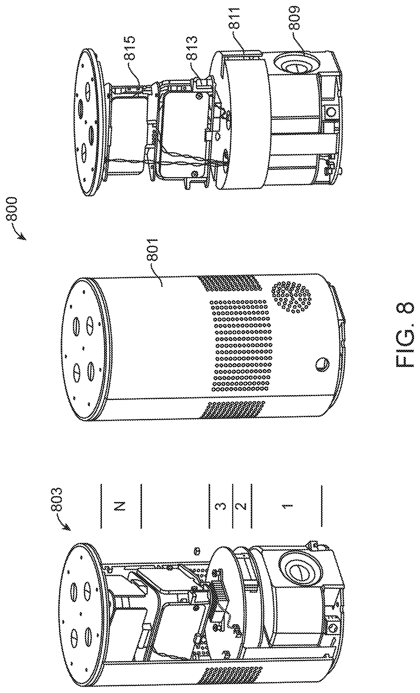
[0016] FIG. 8 is a simplified diagram of a hub device according to an example.
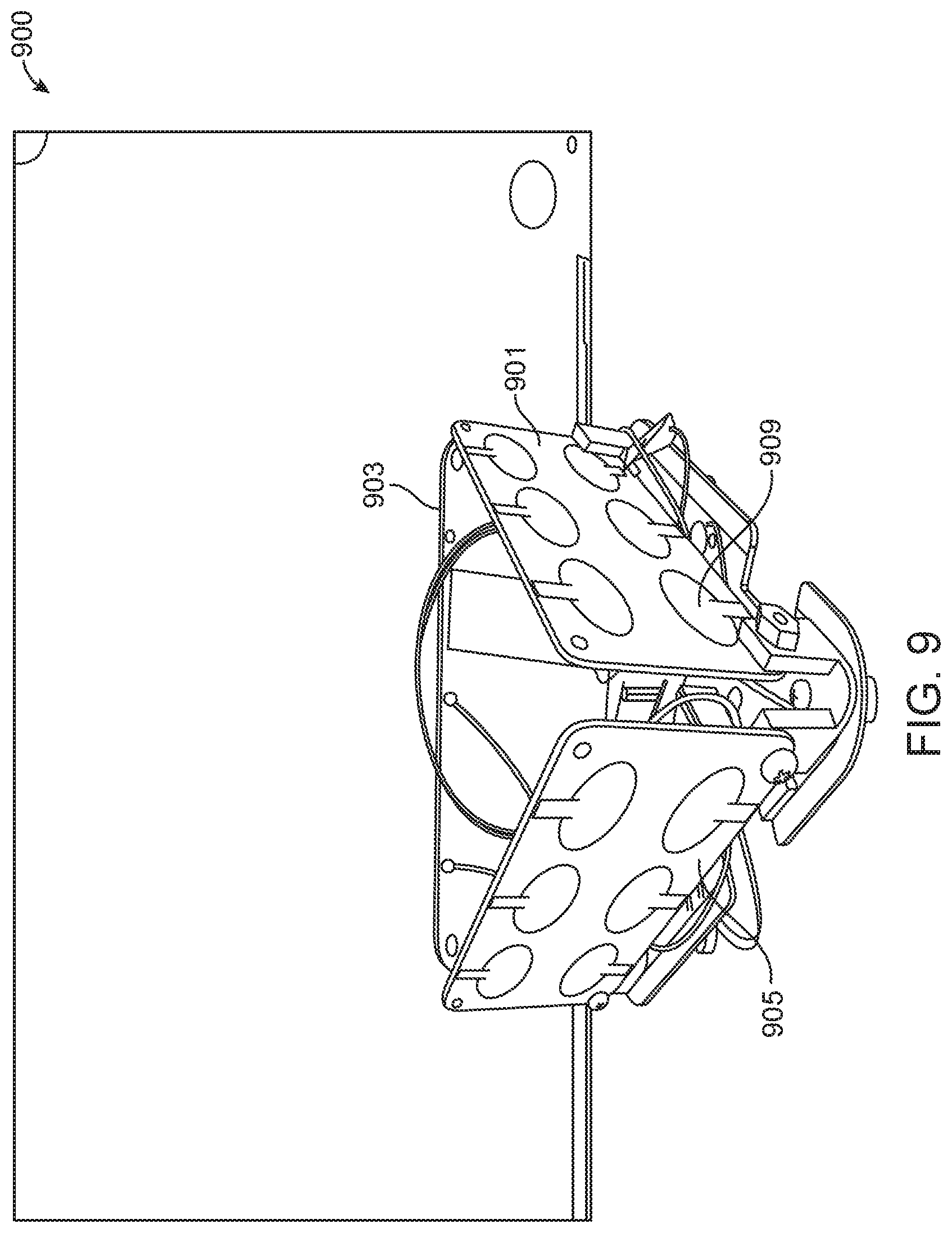
[0017] FIG. 9 is a simplified diagram of an ultra-wide band module for the hub according to an example of the present invention.
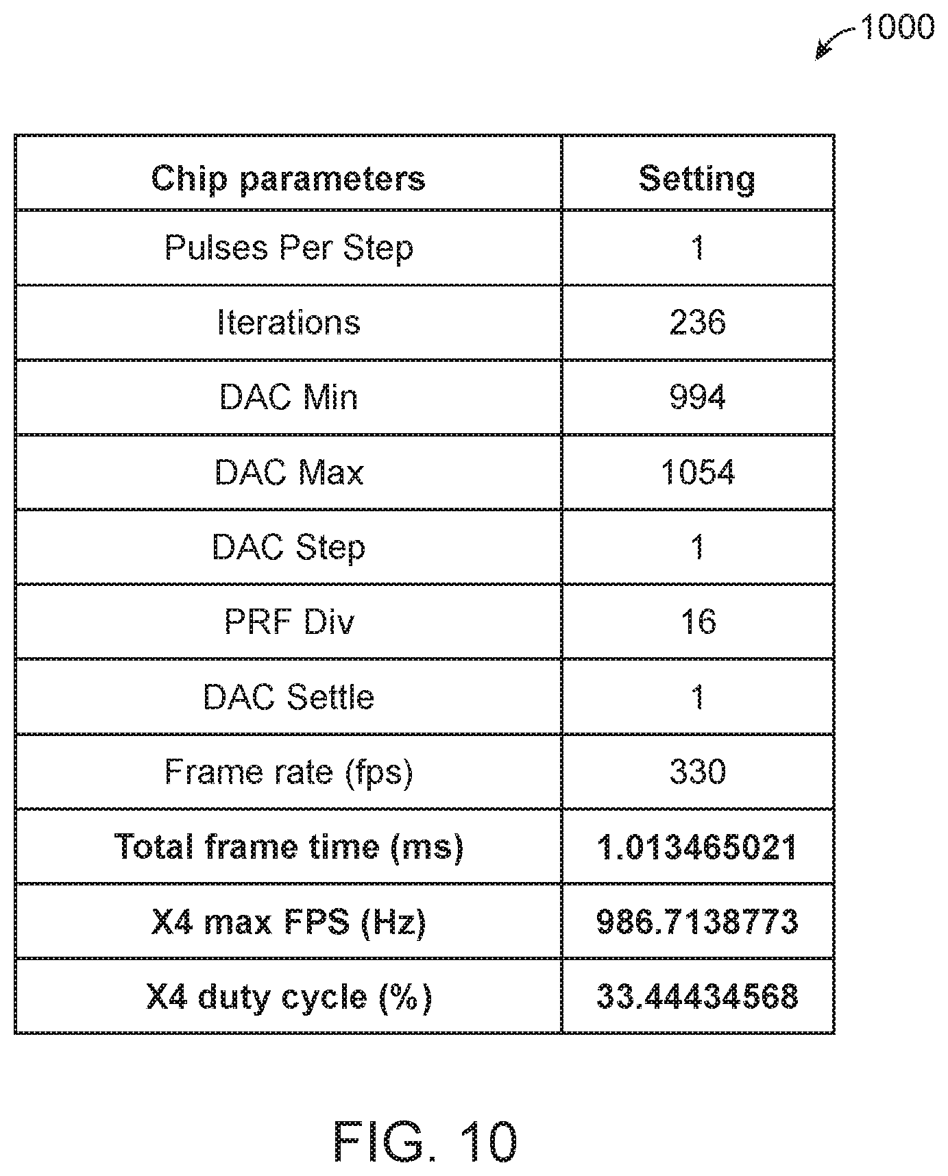
[0018] FIG. 10 is a simplified diagram of electrical parameters according to an example for the ultra-wide band module in the present invention.
[0019] FIG. 11 is a simplified system diagram of the ultra-wide band module according to an example of the present invention.
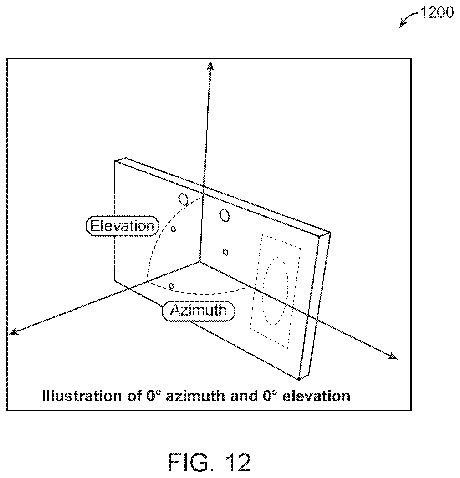
[0020] FIG. 12 is an example of antenna array parameters for the ultra-wide band module according to the present invention.
[0021] FIG. 13 is an example of antenna array configuration for the ultra-wide band module according to the present invention.
DETAILED DESCRIPTION OF THE EXAMPLES
[0022] According to the present invention, techniques related to a method, and system, for processing ultra-wide band signals using a plurality of antenna array are provided. In an example, the plurality of antenna array, including a receiving antenna array and a transmitting antenna array configured to capture and transmit signals in an omni-directional manner. Merely by way of examples, various applications can include daily life, and others.
[0023] FIG. 1 is a simplified diagram of a radar/wireless backscattering sensor system 100 according to an example of the present invention. This diagram is merely an example, which should not unduly limit the scope of the claims herein. In an example, the system is a wireless backscattering detection system. The system has a control line 101 coupled to a processing device. The control line is configured with a switch to trigger an initiation of a wireless signal. In an example, the system has a waveform pattern generator 103 coupled to the control line. The system has an rf transmitter 105 coupled to the waveform pattern generator. The system has transmitting and receiving antenna 107. In an example, the system has a transmitting antenna coupled to the rf transmitter and an rf receiver 105, which is coupled to an rf receiving antenna. In an example, the system has an analog front end comprising a filter 109. An analog to digital converter 111 coupled to the analog front end. The system has a signal-processing device 113 coupled to the analog to digital converter. In a preferred example, the system has an artificial intelligence module 113 coupled to the signal-processing device. The module is configured to process information associated with a backscattered signal captured from the rf receiving antenna. Further details of the present system can be found through out the specification and more particularly below.
[0024] Antenna
[0025] In an example, multiple aspects of antenna design can improve the performance of the activities of daily life ("ADL") system. For example in scanning mode the present technique continuously looks for moving human targets (or user) to extract ADL or fall. Since these can happen anywhere in the spatial region of a home, the present system has antennas that have wide field of view. Once the human target is identified, the technique focuses signals coming only from that particular target and attenuate returns from all other targets. This can be done by first estimating location of the target from our technique using wide field of view antennas and then focusing RF energy on the specific target of interest once it has been identified. In an example, the technique can either electronically switch a different antenna that has narrow field of view or could use beam forming techniques to simultaneously transmit waves from multiple transmit antenna and control their phase such that the RF energy constructively builds around the target of interest where as it destructively cancels everywhere else. This return will be much cleaner and can boost the performance of our ADL+fall+vital sign sensors.
[0026] In another example considers the layout of the antennas itself. In an example, the technique places transmit and receive antennas in various different physical configurations (ULA, circular, square, etc.), that can help us establish the direction from which the radar signal returns, by comparing phases of the same radar signal at different receiving antennas. The configurations can play a role because different configurations enable direction of arrival measurement from different dimensions. For example, when the human target falls the vertical angle of arrival changes from top to bottom, therefore a vertical ULA is better suited to capture that information. Likewise during walking horizontal angle of arrival of the signal varies more therefore it makes sense to use horizontal ULA is more sensitive and therefor can provide additional information for our algorithm. Of course, there can be other variations, modifications, and alternatives.
[0027] RF Unit
[0028] In an example, the wireless RF unit can be either pulsed doppler radar or frequency modulated continuous wave (FMCW) or continuous wave doppler (CW). In an example, on the transmit side it will have standard RF units like VCO, PLL, among others. On the receive side it can have matched filter, LNA, mixer, and other elements. The multiple antennas can be either driven by a single transmit/receive chain by sharing it in time or have one each chain for each of the antennas.
[0029] Waveform Unit
[0030] In an example, waveform pattern generator generates control signals that define the type of radar signal that is generated by the radar RF unit. For example for FMCW, it can generate triangular wave of specific slope and period, which will linearly sweep the frequency of the RF unit according to this parameter. For a pulsed doppler radar, the technique will hold generate pulse of specific width and period, which will modulate the RF output accordingly.
[0031] Baseband Unit
[0032] In an example, the gain and filter stage filters the radar returns to remove any unwanted signals and then amplifies the remaining signal with different techniques. For example, the present artificial intelligence or AI technique can determine what target is desirably tracked and provide feedback to the AI technique, that will filter out radar return from any and all other signals except for the signal that is desirably tracked. If human target is moving the return signal will be fluctuating, in that case, the technique applies automatic gain control (AGC) to find the optimal gain, so that entire dynamic range of ADC in the subsequent stage is satisfied. In an example, the return signal is converted to digital samples by analog-to-digital converters (ADC), among other front-end elements.
[0033] FIG. 2 is a simplified diagram of a sensor array 200 according to an example of the present invention. This diagram is merely an example, which should not unduly limit the scope of the claims herein. Shown is a sensor array. The sensor array includes a plurality of passive sensors 201. In an example, the plurality of passive sensors are spatially disposed in spatial region of a living area. The sensor array has active sensors, such as one or more radar sensors 203. Additionally, the array has a feedback interface 205, such as a speaker for calling out to a human target in the spatial region of the living area.
[0034] In an example, the present technique is provided to identify various activities in home using non-wearable. In an example, the technique is at least privacy intrusive as possible, and will use sensors that are less intrusive. Examples of sensors can include, without limitation, a wireless backscatter (e.g., radar, WiFi.), audio (e.g., microphone array, speaker array), video (e.g., PTZ mounted, stereo), pressure mats, infrared, temperature, ultraviolet, humidity, pressure, smoke, any combination thereof, and others.
[0035] Active Sensor for RADAR
[0036] In an example, the technique can use wireless backscattering to measure motion of human, a location, and an environmental state, such as door opening/closing, or other environmental condition. In an example, the wireless backscattering can also be used to measure a vital sign, such as a heart rate and respiration rate, among others. In an example, the wireless techniques can work in non-line of sight, and is non intrusive compared to camera or microphone, or others. In an example, the technique can use radar\backscatter sensor for two purposes (1) to find the location of an action; and (2) sense different activities associated with the action. Of course, there can be other variations, modifications, and alternatives.
[0037] In an example, the present technique and system includes a radar system that operates on multiple frequency bands, such as below 10 GHz, around 24 GHz, 60 GHz, 77-81 GHz, among others. In an example, different frequency interacts differently with various objects in our environment. In an example, available signal bandwidth and permissible signal power are also regulated differently at different frequency bands. In an example, the present techniques optimally combine reflections coming from a reflector from multiple frequency bands to achieve large coverage, and/or improve accuracy. Of course, there can be other variations, modifications, and alternatives.
[0038] In an example, each radar is working at a particular frequency band will be using multiple transmit and receive antennas, as shown. In an example, using these multiple transmitters, the technique can perform transmit beam forming to concentrate radar signal on a particular target. In an example, the technique uses multiple receivers to collect reflected signals coming from various reflectors (e.g., human body, walls). After further processing this will allow us to find the direction of the reflector with respect to the radar. In an example, the technique also uses multiple transmitter and receiver to form virtual array, this will allow emulate the radar array with large element by using small number of transmitter and receiver chains. The main benefit is to improve the angle resolution without using a large array, saving space and component cost. In an example, different antenna array configurations to improve coverage (using beam forming) or add 3D localization capability (using 2-D array) are included.
[0039] In an example using standard radar signal modulation techniques, such as FMCW/UWB, on MIMO radar, the technique will first separate signals coming from different range and angle. The technique will then identify static reflectors, such as chairs, walls, or other features, from moving ones, such as human targets, pets, or the like. For moving objects that are tracked, the technique will further process signals for each of the reflectors. As an example, the technique will use different techniques to extract raw motion data (e.g., like spectrogram). In an example, the technique will apply various filtering process to extract periodic signals generated by vital signs, such as heart rate, respiration rate, among others. In an example, both the raw motion data and extracted vital signs will be passed to a downstream process, where they are combined with data from other sensors, such as radar outputs operating at different frequency or completely different sensors to extract higher insights about the environment. Of course, there can be other variations, modifications, and alternatives.
[0040] Audio Sensor
[0041] In an example, the present technique uses a sensor array that has a multiple microphone array. In an example, these microphones will be use to ascertain the direction of arrival of any audio signal in the environment. In an example, the microphone in conjunction with other sensors, such as radar, will be vital in performing two tasks: 1st it will augment radar signal to identify various activities (walking produces a different sound than sitting), if the target is watching TV it is much easier to ascertain it with audio signal; and 2nd in case of emergency like fall, the technique can use the radar signal to identify the location of the fall and then beam form microphone array towards that location, so that any audio signal produced by the target can be captured. Of course, there can be other variations, modifications, and alternatives.
[0042] Sensor Fusion and Soft Sensors
[0043] In addition to a radar sensor, which is consider as active sensors the present sensor system (e.g., box, boxes) will also have additional passive sensors that captures the sound, chemical signature, environmental conditions. Each of these of the sensors captures different context about the home that the human being tracking is living in or occupying. In an example, the UV sensor can monitor how often the sunlight comes in the room. In an example, light sensors determine a lighting condition of the human's home or living area.
[0044] In an example, a microphone array can have many functions, such as use to sense sound in the room, to figure out how long the human has spent watching TV, or how many time they went to bathroom by listening to the sound of toilet flushing or other audio signature. In an example, the present technique can use creative solutions where it can use the active sensor to find the location of the person and then tune the microphone array to enhance the sound coming from that location only, among other features. In an example, the technique can call the sensors that are derived from the hardware sensors using specific algorithms as software sensors or soft sensors. So the same hardware sensors can be used for many different applications by creating different software sensors. Here the software sensors can combine signals from one or more sensors and then apply sensor fusion and AI techniques to generate the desired output. Of course, there can be other variations, modifications, and alternatives.
[0045] Soft Sensor for Detecting Cooking and Eating Habits
[0046] In example, radar sensors can determine information about a human's location within a home, like if they are in kitchen area, or other. In an example, when the human target turns on the microphone oven, it generates specific RF signature that can be tracked. In an example, the technique can combine this information to infer if the human target walked to the kitchen and turned on the microphone. Likewise, when the human target prepares food in kitchen he/she can make lot of specific noise like utensils clattering, chopping, or other audio signature. So if a human target goes to kitchen spends sometime time in the kitchen, and the present microphone pick these sounds, the technique can infer that food is cooking or other activity.
[0047] Soft Sensor for Detecting Bathroom Habits
[0048] In an example, toileting frequency can be a very valuable indication of ones wellness. The present technique can track if a human went to the bathroom using the radar or other sensing techniques. In an example, additionally, the technique can pick sound signature of toilet flushing. In an example, the technique combines these two pieces of information, which can be correlated to toileting frequency. In an example, similarly, bathing is a unique activity that requires 4-5 minutes of specific movements. By learning those patterns, the technique can figure out ones bathing routines.
[0049] Soft Sensor for Detecting Mobile Habits
[0050] In an example, different sensors are triggered by different motion of a human target. In an example, radar can detect human fall by looking at micro doppler patterns generating by different part of the target during falls. In an example, the technique can also simultaneously hear a fall from microphone arrays and vibration sensors. In an example, the technique can also detect how pace of movement changes for an individual over a long duration by monitoring the location information provided by radar or other sensing technique. In an example, likewise, the technique can gather unstable transfers by analyzing the gait of the target. In an example, the technique can find front door loitering by analyzing the radar signal pattern. In an example, the technique can figure out immobility by analyzing the radar return. In this case, the technique can figure out the target's presence by analyzing the target's vital signs, such as respiration rate or heart rate or by keeping track of the bread crumb of the target's location trace.
[0051] In any and all of the above cases, the technique can also learn about the exact environmental condition that triggered a particular state. For example, the technique can figure out whether a human target was immobile because the target was watching TV or a video for long duration or the target was simply spending a lot of time in their bed. And these can be used to devise incentives to change the target's behavioral pattern for better living.
[0052] Soft Sensor for Detecting Vital Signs
[0053] In an example, the technique can estimate vital signs of a person by sensing the vibration of the target's body in response to the breathing or heart beat, each of the actions results in tiny phase change in the radar return signals, which can be detected. In an example, the technique will use several signal processing techniques to extract them. Of course, there can be other variations, modifications, and alternatives.
[0054] In an example, different frequency radio wave interact with environment differently. Also phase change due to vital signs (HR,RR) differs by frequency, for example phase change for a 77 GHz radar is much higher than for a 10 GHz radar. Thus 77 GHz is more appropriate for estimating heart-beat more accurately. But higher frequency typically attenuates much more rapidly with distance. Therefore, lower frequency radar can have much larger range. By using multi-frequency radar in the present technique can perform these vital trade-offs.
[0055] Soft Sensor for Detecting Sleeping Habits
[0056] In an example, the present radar sensors can detect motions that are generated during sleep, such as tossing and turning. In an example, radar sensors can also sense vital signs like respiration rate and heart rate as described earlier. In an example, now combining the pattern of toss and turn and different breathing and heart beat pattern, the technique can effectively monitor the target's sleep. Additionally, the technique can now combine results from passive sensors, such as a thermometer, UV, photo diode, among others, to find correlation between certain sleep pattern and the environmental conditions. In an example, the technique can also use the sleep monitor soft sensor to learn about day/night reversal of sleep, and the associated environmental condition by looking at different passive sensors. In an example, the techniques can be valuable in providing feedback to improve the human target's sleep. For example, the technique can determine or learn that certain environmental condition results in better sleep and prescribe that to improve future sleep.
[0057] Soft Sensor for Security Applications
[0058] In an example, the technique can repurpose many of the sensors described before for security applications. For a security application, the technique determines where one or more person is located, which can be detected using a presence detection sensor that is build on top of radar signals. In an example, the technique can eliminate one or many false positive triggered by traditional security systems. For example, is a window is suddenly opened by a wind the technique (and system) will look at presence of human in the vicinity before triggering the alarm. Likewise, combination of vital signs, movement patterns, among others, can be used a biometric to identify any human target. If an unknown human target is detected in the vicinity at certain time of the day, the technique can trigger an alarm or alert.
[0059] In an example, any one of the above sensing techniques can be combined, separated, or integrated. In an example, n addition to radar and audio sensors, other sensors can be provided in the sensor array. Of course, there can be other variations, modifications, and alternatives.
[0060] FIG. 3 is a simplified diagram of a system 300 according to an example of the present invention. This diagram is merely an example, which should not unduly limit the scope of the claims herein. As shown, the system has hardware and method (e.g., algorithm), cloud computing, personalized analytics, customer engagement, and an API to various partners, such as police, medical, and others. Further details of the present system can be found throughout the present specification and more particularly below.
[0061] FIG. 4 is a detailed diagram 400 of hardware apparatus according to an example of the present invention. This diagram is merely an example, which should not unduly limit the scope of the claims herein. As shown, the hardware units include at least a hub device 401, node 403, and mobile node 405, each of which will be described in more detail below.
[0062] In an example, the hub includes various sensing devices. The sensing devices, include, among others, a radar, a WiFi, a Bluetooth, a Zigbee sniffer, a microphone and speakers, a smoke detector, a temperature detector, a humidity detector, a UV detector, a pressure detector, MEMS (e.g., accelerometer, gyroscope, and compass), a UWB sensors (for finding locations of all the deployed elements relative to each other), among others. In an example, the hub is a gateway to internet via WiFi, GSM, Ethernet, landline, or other technique. The hub also connects to other units (Mini Node/Mobile Node) via Bluetooth, WiFi, Zigbee, UWB and coordinates them with each other. In an example, certain data processing, such as noise removal, feature extraction to reduce amount of data uploaded to cloud is included. In an example, the hub alone can be sufficient to cover a small living space. In an example, the hub is deployed as a single device somewhere in a desirable location (e.g., middle of the living space) so that it has good connectivity to all other units. An example of such deployment is provided in the Figure below.
[0063] FIG. 5 is a simplified diagram 500 of a hub in a spatial region according to an example of the present invention. This diagram is merely an example, which should not unduly limit the scope of the claims herein. As shown, the hub is deployed in the middle of the living space in a house.
[0064] In an example, as shown in FIG. 6, the system 600 has sensors, which is a subset of sensors in the hub. The sensors are configured to in various spatial locations to improve coverage area and improve accuracy for detection of critical events (e.g., fall, someone calling for help). The sensors also communicate with the hub via WiFi, Bluetototh, ZigBee or UWB, or other technique. Additionally, the sensors or each mini node is deployed in a bathrooms, where chances of fall is high, a kitchen, where we can learn about eating habits by listening to sounds, RF waves, vibrations, or a perimeter of the living space, that will allow us to learn approximate map of the space under consideration, among other locations. Additionally, each of the mini nodes can save power and costs by adding more complexity on the hub. This can even enable us to operate on battery for extended periods. For example, each of the nodes can have only single antenna WiFi and hub could have multiple antennas, for WiFi based sensing. Additionally, each of the nodes use simpler radar (e.g., single antenna doppler) vs MIMO FMCW in the HUB. Additionally, each node can be configured with a single microphone whereas the hub can have array of microphone. Of course, there can be other variations, modifications, and alternatives. As shown, each node is configured in a kitchen, shower, perimeter, or other location.
[0065] FIG. 7 is a simplified diagram 700 of a mobile node according to an example of the present invention. This diagram is merely an example, which should not unduly limit the scope of the claims herein. In an example, each mobile node is a subset of sensors in the hub. The mobile node sensors include a camera such as RGB or IR. In an example, each of the nodes and hub collaboratively figure out interesting events, and pass that information to the mobile node. The technique then goes to the location and probes further. In an example, the camera can be useful to visually find what is going on in the location. In an example, freewill patrolling can be use to detect anything unusual or to refine details of the map created based on perimeter nodes. In an example, onboard UWB can enable precise localization of the mobile node, which can also enable wireless tomography, where the precise RGB and wireless map of the living space is determined. As shown, the mobile node, such as a mobile phone or smart phone or other movable device, can physically move throughout the spatial location. The mobile node can also be a drone or other device. Of course, there can be other variations, modifications, and alternatives. Further details of an example of a hub device can be found throughout the present specification and more particularly below.
[0066] FIG. 8 is a simplified diagram of a hub device 800 according to an example of the present invention. As shown, the hub device has a cylindrical housing 801 having a length and a diameter. The housing has an upper top region and a lower bottom region in parallel arrangement to each other. In an example, the housing has a maximum length of six to twenty four inches and width of no longer than six inches, although there can be other lengths and widths, e.g., diameters. In an example, the housing has sufficient structural strength to stand upright and protect an interior region within the housing.
[0067] In an example, the housing has a height characterizing the housing from a bottom region to a top region. In an example, a plurality of levels 803 are within the housing numbered from 1 to N, wherein N is an integer greater than two, but can be three, four, five, six, seven, and others.
[0068] As shown, various elements are included. A speaker device 809 configured within the housing and over the bottom region, as shown. The hub device also has a compute module 811 comprising a processing device (e.g., microprocessor) over the speaker device. The device has an artificial intelligence module configured over the compute module, a ultra-wide band ("UWB") module 813 comprising an antenna array configured over the artificial intelligence module, and a frequency modulated continuous wave ("FMCW") module 815 with an antenna array configured over the UWC module. In an example, the FMCW module being configured to process electromagnetic radiation in a frequency range of 24 GHz to 24.25 GHz. In an example, the FMCW module outputs an FMCW signal using a transmitter, and receives back scattered signals using a receiver, such as a receiver antenna. The device has an audio module configured over the FMWC module and an inertial measurement unit ("IMU") module configured over the FMCW module. In an example, the audio module comprises a microphone array for detecting energy in a frequency range of sound for communication and for detecting a sound energy. In an example, the IMU module comprises at least one motion detection sensor consisting of one of a gyroscope, an accelerometer, a magnetic sensor, or other motion sensor, and combinations thereof.
[0069] As shown, the speaker device, the compute module, the artificial intelligence module, the UWB module, the FMCW module, the audio module, and the IMU module are arranged in a stacked configuration and configured, respectively, in the plurality of levels numbered from 1 to N. In an example, the speaker device comprises an audio output configured to be included in the housing. As shown, the speaker device is spatially configured to output energy within a 360 degree range from a midpoint of the device.
[0070] In an example, the compute module comprises a microprocessor based unit coupled to a bus. In an example, the compute module comprises a signal processing core, a micro processor core for an operating system, a synchronizing processing core configured to time stamp, and synchronize incoming information from each of the FMCW module, IMU module, and UWB module.
[0071] In an example, the device further comprises a real time processing unit configured to control the FMCW switch or the UWB switch or other switch requiring a real time switching operation of less than 1/2 milliseconds of receiving feedback from a plurality of sensors.
[0072] In an example, the device has a graphical processing unit configured to process information from the artificial intelligence module. In an example, the artificial intelligence module comprises an artificial intelligence inference accelerator configured to apply a trained module using a neural net based process. In an example, the neural net based process comprises a plurality of nodes numbered form 1 through N. Further details of the UWB module can be found throughout the specification and more particularly below.
[0073] FIG. 9 is a simplified diagram of an ultra-wide band module 900 for the hub according to an example of the present invention. As shown is ultra-wide band rf sensing apparatus or module. In an example, the apparatus has at least three antenna arrays 901, 903, 905 configured to sense a back scatter of electromagnetic energy from spatial location of a zero degree location in relation to a mid point of the device through a 360 degrees range where each antenna array is configured to sense a 120 degree range. As shown, each of the three antenna arrays comprises a support member, a plurality of transmitting antenna 909 spatially configured on a first portion of the support member. The support member also has a transmitting integrated circuit coupled to each of the plurality of transmitting antenna and configured to transmit an outgoing UWC signal. Each of the antenna array also has a plurality of receiving antenna spatially configured on second portion of the support member. The support member also has a receiving integrated circuit coupled to each of the plurality of receiving antenna and configured to receive an incoming UWB signal and configured to convert the UWC signal into a base band.
[0074] In an example, the device has a triangular configuration comprising a first antenna array, a second antenna array, and a third antenna array included in the at least three antenna arrays. The three arrays provide a 360 degree visibility range as measured from a horizontal plane, and a 80 degree visibility range as measured from a vertical plane normal to the horizontal plane. As previously noted, the three arrays are enclosed in a housing that provides mechanical support. In an example, each of the sensor arrays is provided on a substrate member to be configured in the triangular configuration. The substrate member has a face arranged in a normal manner in a direction to each of the support members.
[0075] In an example, the UWB module can operate at a center frequency of 7.29 GHz and a bandwidth of .about.1.5 GHz with multiple antenna arrays to achieve the FCC/ETSI compliance standard. In an example, the module has a combined horizontal field-of-view of 360 degrees about a center point of the module. In an example, the module has a range greater than 10 meters, but can be shorter and longer. In an example, the module is configured to achieve a transmission and a receive rate of frames per second (FPS) equal to or greater than 330 per Tx-Rx. In an example, the module has a combined horizontal field of view of 360 degrees achieved using three (3) antenna arrays, each of which covering 120 degrees. In an example, each antenna array comprises of 1-TX and 4-RX. Each antenna array is configured to complete the acquisition of a frame within 1 millisecond or less. Accordingly, a total of three (3) milliseconds covers all three (3) sectors, achieving a frame rate of 330 fps per sector (per Tx-Rx) in an example. In an example, the module has programmability of various parameters similar to Novelda X4M03 module. In an example, the module is a hybrid architecture that has four by four radar integrated circuit devices in MIMO configuration that switches between the three antenna arrays. The configuration is capable of simultaneous capturing of all four Rx frames in an antenna array. Further details of the present UWB module is provided throughout the present specification and more particularly below.
[0076] FIG. 10 is a simplified diagram 1000 of electrical parameters according to an example for the ultra-wide band module. In an example, various parameters are as listed in the table. Each of the parameters listed are suggested and can be adjusted to minimize cost and complexity, while still achieving performance. In an example, the module has a data transfer of 3.2 MBps (e.g., 330 fps.times.200 frame length.times.2 bytes.times.2.times.4 receivers.times.3 modules. In an example, the module can include a micro controller unit to communicate with X4 SoC through an SPI interface. In an example, a central processing unit communicates with a compute module through a serial interface such as a universal serial bus, i.e., USB. The micro controller is configured on a board with sufficient memory to store raw data. In an example, the memory has a capacity of greater than 128 MB such as a 128 MB SDRAM. Further details of the electrical parameters configured within a system diagram are provided below.
[0077] FIG. 11 is a simplified system diagram 1100 of the ultra-wide band module according to an example of the present invention. As shown, the system has a micro controller 1101, such as an integrated circuit sold under ATSAM4E16E by Microchip Technology Inc. of 2355 West Chandler Blvd., Chandler, Ariz., USA 85224-6199. The micro controller has a serial interface, such as the universal serial interface, USB. The controller is coupled to random access memory 1105 for storing raw data, and a clock and other miscellaneous circuits 1103. In an example, the output of the controller communicates 1107 with four XETHRU X4 SoCs manufactured by Novelda AS of Norway.
[0078] In an example, the basic components of the X4 SoC are a transmitter, a receiver, and related control circuits. The system is controlled by a system controller and is configurable through a 4(6)-wire serial peripheral interface (SPI). In an example, the X4 receive path (RX) consists of a low noise amplifier (LNA), a digital-to-analog converter (DAC), 1536 parallel digital integrators as well as an output memory buffer, accessible through the SPI. The RX is tightly integrated with the transmitter (TX) and is designed for coherent integration of the received energy. The X4 transmit path (TX) consists of a pulse generator capable of generating pulses at a rate of up to 60.75 MHz. The output frequency and bandwidth are designed to fit worldwide regulatory requirements. The radar transceiver is able to operate completely autonomously and can be programmed to capture data at predefined intervals and then alert or wake up a host MCU or DSP through dedicated interrupt pins. A power management unit controls the on-chip voltage regulators and enables low-power applications to use efficient duty cycling by powering down parts of the circuit when they are not needed. The system can be configured to consume less than 1 mW in idle mode when all analog front end components are turned off. As shown, each of the four X4 SoCs is coupled in parallel to a switch.
[0079] In an example, the switch 1109 is coupled to each antenna array as shown. In an example, the switch can be one listed under HMC241/HMC7992/ADRF5040 SP4T RF Switches of Analog Devices, Inc. The switches are non-reflective RF switches from DC to 12 GHz for 4G cellular, milcom, and radio applications. Examples of HMC241, HMC7992, and ADF5040 are radio frequency (RF) nonreflective/absorptive single pull, quad throw (SP4T) switches that can interface with 3.3 V, TTL, LVTTL, CMOS, and LVCMOS logic. The switches operate from DC to 12 GHz frequency range. The HMC241 is a GaAs MMIC RF switch that operates in the DC to 4 GHz range. The switch takes a single supply at +5 V. The HMC7992 has a 100 MHz to 6 GHz frequency range. The ESD rating is for this switch 2 kV (HBM) class 2. The HMC7992 takes a single voltage supply from .+-.3.3 V to +5 V. The ADRF5040 comes in a small 4 mm.times.4 mm LFCSP package and requires a dual .+-.3.3 V supply. The switch operates in the 9 kHz to 12 GHz range. The ADRF5040 has the added benefit of being 4 kV (HBM) ESD rating. HMC241, HMC7992, and ADF5040 are ideal for 4G cellular infrastructure such as base stations and repeaters as well as military communications and industrial test and measurement applications. Of course, there can be other variations, modifications, and alternatives.
[0080] In an example, the UWC module comprises a switch configured between a plurality of UWC transceivers. The switch is configured to select one of the three antenna arrays to sense the back scatters while the other two antenna arrays are turned off. In an example, the switch is an rf switch such as the one listed under part number ADRF-5040 manufactured by Analog Devices, Inc. In an example, the UWC module also has a controller configured to control the switch and the three antenna array. In an example, the controller cycles through a predetermined process to decide which one of the three antenna array to activate while the other two antenna arrays are turned off.
[0081] In an example, the at least three antenna array are configured to sense electromagnetic energy ranging from 6 to 8 GHz in frequency. As noted, the sensing apparatus is spatially positioned within a center of a geographic location of a room to detect movement of human user.
[0082] In an example, the present invention provides a method processing an electromagnetic signal generated from an ultra wide band rf signal to detect an activity of a human user. Referring to FIG. 11, the method includes generating a base band outgoing UWC signal from a transmitting integrated circuit, which is coupled to a micro controller device. The method includes transferring and then receiving the base band outgoing UWC signal at a switch device, which is coupled to the micro controller. The switch is configured to direct the outgoing UWC signal using the switch device to one of three antenna arrays. In an example, the three antenna array have been configured in a triangular configuration to transmit the outgoing UWC signal from spatial location of a zero degree location in relation to a mid point of the device through a 360 degrees visibility range where each antenna array is configured to sense a 120 degree range in a horizontal plane. Each of the antenna array is configured to sense and transmit at least an 80 degree visibility range as measured from a vertical plane that is normal to the horizontal plane. In an example, each of the three antenna arrays comprise a support member, a plurality of transmitting antenna spatially configured on a first portion of the support member, a transmitting integrated circuit coupled to each of the plurality of transmitting antenna and configured to transmit the outgoing UWC signal. Each of the antenna array also has a plurality of receiving antenna spatially configured on second portion of the support member. The antenna array also has a receiving integrated circuit coupled to each of the plurality of receiving antenna and configured to receive an incoming UWB signal and configured to convert the UWC signal into a base band. In an example, the method also receives a back scattered electromagnetic signal caused by an activity of a human user redirecting the outgoing UWB signal. In an example, the received signals are processed, using the artificial intelligence module to form an output. Of course, there can be other variations, modifications, and alternatives.
[0083] FIG. 12 is an example 1200 of antenna array parameters for the ultra-wide band module according to the present invention. As shown, each antenna array has one 1-Tx and four 4-Rx. Each Tx/Rx is designed to cover 120 degree azimuth field of view and maximize elevation field of view as desirable. In an example, serial fed patch antennas can be used. In an example, the antennas are fabrication using material such as a Rogers 4350 substrate. In an example, the antennas can be an integrated WiFi filter, if desired, optimized for frequencies between 6.0 and 8.5 GHz. In an example, the antenna is designed for FCC/ETSI Compliant for TX Center frequency. Of course, there can be other variations, modifications, and alternatives.
[0084] FIG. 13 is an example of antenna array configuration 1300 for the ultra-wide band module according to the present invention. As shown, the antenna array is spatially provided on a support member, such as a board. The antenna array comprises four (4) Rx in an antenna array that are in a two-dimensional (2D) configuration as shown. The Rx4 is aligned with Rx1, Rx2 or Rx3, and separated by lambda over two, as shown. Each of the antennas is separated by lambda over two, as shown. Of course, there can be other variations, modifications, and alternatives.
[0085] In an example, the present invention provides a method processing an electromagnetic signal generated from an ultra wide band rf signal to detect an activity of a human user. In an example, the method includes generating a base band outgoing UWC signal. The method also includes receiving the base band outgoing UWC signal at a switch device and directing the outgoing UWC signal using the switch device to one of three antenna arrays configured in a triangular configuration to transmit the outgoing UWC signal from spatial location of a zero degree location in relation to a mid point of the device through a 360 degrees visibility range where each antenna array is configured to sense a 120 degree range in a horizontal plane. Each of the antenna array is configured to sense and transmit at least an 80 degree visibility range as measured from a vertical plane that is normal to the horizontal plane.
[0086] In an example, each of the three antenna arrays has a support member, e.g., board, printed circuit board. In an example, each array has a plurality of transmitting antenna spatially configured on a first portion of the support member, a transmitting integrated circuit coupled to each of the plurality of transmitting antenna and configured to transmit the outgoing UWC signal, a plurality of receiving antenna spatially configured on second portion of the support member, and a receiving integrated circuit coupled to each of the plurality of receiving antenna and configured to receive an incoming UWB signal and configured to convert the UWC signal into a base band signal. In an example, the method includes receiving a back scattered electromagnetic signal caused by an activity of a human user redirecting the outgoing UWB signal.
[0087] The apparatus of claim 11 wherein the UWB module comprises a micro controller unit coupled to a memory resource, and a clock circuit, the micro controller unit being configured with a universal serial bus interface coupled to the compute module; wherein the compute module is configured with the artificial intelligence module to process information from the back scattered electro magnetic signal from the base band signal to detect the activity of the human entity.
[0088] In an example, the support member comprises a major plane positioned normal to a direction of gravity.
[0089] In an example, the antenna array comprises at least three antenna array spatially arranged in a triangular configuration comprising a first antenna array, a second antenna array, and a third antenna array included in the at least three antenna arrays to provide a 360 degree visibility range as measured from a horizontal plane, and a 80 degree visibility range as measured from a vertical plane normal to the horizontal plane. In an example, the antenna array comprises at least three antenna array spatially arranged in a triangular configuration comprising a first antenna array, a second antenna array, and a third antenna array included in the at least three antenna arrays to provide a 360 degree visibility range as measured from a horizontal plane, and a 80 degree visibility range as measured from a vertical plane normal to the horizontal plane, and further comprising a controller configured to control a switch coupled with each of the three antenna array, the controller cycles through a predetermined process to decide which one of the three antenna array to activate while the other two antenna arrays are turned off.
[0090] In an example, each antenna array comprises 1-TX and 4-RX.
[0091] In an example, the system has a switch device coupled between each of the antenna array and four receive lanes each of which is coupled to the receiving integrated circuit device, one transmit lane coupled to a transmitting integrated circuit device, and a micro controller unit coupled to a bus coupled to the receiving integrated circuit device and the transmitting integrated circuit device, the micro controller unit coupled to a memory resource configured with the micro controller to store raw data from information derived from four receive lanes, the micro controller unit being coupled to a clock.
[0092] In an example, each antenna array comprises 1 TX and four RX. In an example, the system has a switch device coupled between each of the three antenna arrays and four receive lanes each of which is coupled to the receiving integrated circuit device, one transmit lane coupled to a transmitting integrated circuit device, and a micro controller unit coupled to a bus coupled to the receiving integrated circuit device and the transmitting integrated circuit device, the micro controller unit coupled to a memory resource configured with the micro controller to store raw data from information derived from four receive lanes, the micro controller unit being coupled to a clock.
[0093] In an example, the technique transfers learned information and activity information to third parties. The technique teaches itself to learn high level behavior that are indicative of a persons welfare using artificial intelligence techniques. In an example, the present technique will then generate summary of such activities and send it out to the human's loved ones, caretaker or even emergency response team depending on the urgency of the situation. For example for regular days, the technique can simply send short summary like "your mom had a routine activity today", or "She was much less active today." In an example, where the human has a care taker visiting few times a week, the technique can send a notification to them, "It seems she struggles more on yesterday", so that the care taker can pay a visit to make sure everything is fine. Alternatively, the technique can be more acute events like fall, shortness of breathing, or others, that needs quick attention. In these scenarios, the technique can notify medical response team to provide immediate help. Of course, there can be other variations, modifications, and alternatives.
[0094] In an example, the present technique can categorize a human target with the listed ADLs, among others. Examples of ADLs including among others, bathing, brushing teeth, dressing, using toilet, eating and drinking, and sleeping. Other ADLs include preparing meals, preparing drinks, resting, housekeeping, using a telephone, taking medicine, and others. Ambulatory activities including among others walking, doing exercise (e.g., running, cycling), transitional activities (e.g., sit-to-stand, sit-to-lie, stand-to-sit, lie-to-sit in and out of bed or chair), and stationary activities (e.g., sits in sofa, stand for a while, lie in bed or sofa). Of course, there can be other variations, modifications, and alternatives.
[0095] In an alternative example, the present technique can determine activities of a human target with any one of the activities listed. The listed activities, including among others, and combinations of going out, preparing breakfast, having breakfast, preparing lunch, having lunch, preparing dinner, having dinner, washing dishes, having snack, sleeping, watching TV, studying, having a shower, toileting, having a nap, using the Internet, reading a book, shaving, brushing teeth, telephone, listening to music, doing house cleaning, having a conversation, entertain guest, among others.
[0096] In an example, the present technique can also identify a rare event. In an example, the technique identifies when a senior human falls inside a home with no one around. In an example, the technique is robust, without any false negatives. In an example, the technique uses looking at sequence of events that are before to the potential fall and after a potential fall. In an example, the technique combines the contextual information to robustly determine if a fall has occurred. Of course, there can be other variations, modifications, and alternatives.
[0097] In an example, the technique also detects and measures vital signs of each human target by continuous, non-intrusive method. In an example, the vital signs of interest include a heart rate and a respiratory rate, which can provide valuable information about the human's wellness. Additionally, the heart rate and respiratory rate can also be used to identify a particular person, if more than two target humans living in a home. Of course, there can be other variations, modifications, and alternatives.
[0098] By understanding the context of how the target human (e.g., elderly) is doing, the technique can also provide valuable feedback directly to the elderly using a voice interface. For example, the technique can sense a mood of the human based on sequence of activities and vital signs of the human and then ask, "Hi do you want me to call your son". Based upon the feedback from the human, the technique can help connect to a third party (or loved one) if their answer is positive. Of course, there can be other alternatives, variations, and modifications.
[0099] Having described various embodiments, examples, and implementations, it should be apparent to those skilled in the relevant art that the foregoing is illustrative only and not limiting, having been presented by way of example only. Many other schemes for distributing functions among the various functional elements of the illustrated embodiment or example are possible. The functions of any element may be carried out in various ways in alternative embodiments or examples.
[0100] Also, the functions of several elements may, in alternative embodiments or examples, be carried out by fewer, or a single, element. Similarly, in some embodiments, any functional element may perform fewer, or different, operations than those described with respect to the illustrated embodiment or example. Also, functional elements shown as distinct for purposes of illustration may be incorporated within other functional elements in a particular implementation. Also, the sequencing of functions or portions of functions generally may be altered. Certain functional elements, files, data structures, and so one may be described in the illustrated embodiments as located in system memory of a particular or hub. In other embodiments, however, they may be located on, or distributed across, systems or other platforms that are co-located and/or remote from each other. For example, any one or more of data files or data structures described as co-located on and "local" to a server or other computer may be located in a computer system or systems remote from the server. In addition, it will be understood by those skilled in the relevant art that control and data flows between and among functional elements and various data structures may vary in many ways from the control and data flows described above or in documents incorporated by reference herein. More particularly, intermediary functional elements may direct control or data flows, and the functions of various elements may be combined, divided, or otherwise rearranged to allow parallel processing or for other reasons. Also, intermediate data structures of files may be used and various described data structures of files may be combined or otherwise arranged.
[0101] In other examples, combinations or sub-combinations of the above disclosed invention can be advantageously made. The block diagrams of the architecture and flow charts are grouped for ease of understanding. However it should be understood that combinations of blocks, additions of new blocks, re-arrangement of blocks, and the like are contemplated in alternative embodiments of the present invention.
[0102] The specification and drawings are, accordingly, to be regarded in an illustrative rather than a restrictive sense. It will, however, be evident that various modifications and changes may be made thereunto without departing from the broader spirit and scope of the invention as set forth in the claims.
* * * * *
D00000
D00001
D00002
D00003
D00004
D00005
D00006
D00007
D00008
D00009
D00010
D00011
D00012
D00013

XML
uspto.report is an independent third-party trademark research tool that is not affiliated, endorsed, or sponsored by the United States Patent and Trademark Office (USPTO) or any other governmental organization. The information provided by uspto.report is based on publicly available data at the time of writing and is intended for informational purposes only.
While we strive to provide accurate and up-to-date information, we do not guarantee the accuracy, completeness, reliability, or suitability of the information displayed on this site. The use of this site is at your own risk. Any reliance you place on such information is therefore strictly at your own risk.
All official trademark data, including owner information, should be verified by visiting the official USPTO website at www.uspto.gov. This site is not intended to replace professional legal advice and should not be used as a substitute for consulting with a legal professional who is knowledgeable about trademark law.