Bolt Gas Ports
Spangler; Julian James ; et al.
U.S. patent application number 16/670485 was filed with the patent office on 2020-05-21 for bolt gas ports. This patent application is currently assigned to Daniel Defense, Inc.. The applicant listed for this patent is Daniel Defense, Inc.. Invention is credited to Marvin C. Daniel, Julian James Spangler.
| Application Number | 20200158452 16/670485 |
| Document ID | / |
| Family ID | 70727466 |
| Filed Date | 2020-05-21 |


| United States Patent Application | 20200158452 |
| Kind Code | A1 |
| Spangler; Julian James ; et al. | May 21, 2020 |
Bolt Gas Ports
Abstract
A bolt may be provided for a bolt carrier. The bolt carrier may comprise a gas inlet, a gas expansion chamber, a bolt bore, and the bolt. The gas expansion chamber that may receive a pressurized gas from the gas inlet. The bolt may be disposed in the bolt bore in the bolt carrier. The bolt may comprise a gas ring groove, a gas ring assembly disposed in the gas ring groove, and at least one gas port. The gas ring assembly may be adjacent to the bolt bore. The at least one gas port may provide a pathway for the pressurized gas from the gas expansion chamber to a volume underneath the gas ring assembly to increase a radial sealing force between the gas ring assembly and the bolt bore.
| Inventors: | Spangler; Julian James; (Savannah, GA) ; Daniel; Marvin C.; (Pooler, GA) | ||||||||||
| Applicant: |
|
||||||||||
|---|---|---|---|---|---|---|---|---|---|---|---|
| Assignee: | Daniel Defense, Inc. Black Creek GA |
||||||||||
| Family ID: | 70727466 | ||||||||||
| Appl. No.: | 16/670485 | ||||||||||
| Filed: | October 31, 2019 |
Related U.S. Patent Documents
| Application Number | Filing Date | Patent Number | ||
|---|---|---|---|---|
| 62770600 | Nov 21, 2018 | |||
| Current U.S. Class: | 1/1 |
| Current CPC Class: | F41A 3/26 20130101; F41A 5/24 20130101 |
| International Class: | F41A 5/24 20060101 F41A005/24; F41A 3/26 20060101 F41A003/26 |
Claims
1. A bolt carrier comprising: a gas inlet; a gas expansion chamber that receives a pressurized gas from the gas inlet; a bolt bore; and a bolt disposed in the bolt bore, the bolt comprising, a gas ring groove, a gas ring assembly disposed in the gas ring groove wherein the gas ring assembly is adjacent the bolt bore, and at least one gas port that provides a pathway for the pressurized gas from the gas expansion chamber to a volume underneath the gas ring assembly to increase a radial sealing force between the gas ring assembly and the bolt bore.
2. The bolt carrier of claim 1, wherein the gas ring assembly comprises one ring.
3. The bolt carrier of claim 2, wherein the one ring comprises a gap.
4. The bolt carrier of claim 1, wherein the gas ring assembly comprises a plurality of rings.
5. The bolt carrier of claim 4, wherein each of the plurality rings comprises a gap.
6. The bolt carrier of claim 1, wherein the at least one gas port is vertical.
7. The bolt carrier of claim 1, wherein the at least one gas port is lateral.
8. The bolt carrier of claim 1, wherein the bolt carrier is disposed within a firearm.
9. A bolt comprising: a gas ring groove; a gas ring assembly disposed in the gas ring groove; and at least one vertical gas port that provides a pathway to a volume underneath the gas ring assembly.
10. The bolt of claim 9, wherein the gas ring assembly comprises one ring.
11. The bolt of claim 10, wherein the one ring comprises a gap.
12. The bolt of claim 9, wherein the gas ring assembly comprises a plurality of rings.
13. The bolt of claim 12, wherein each of the plurality rings comprises a gap.
14. The bolt of claim 9, wherein the bolt is disposed in a bolt carrier.
15. A bolt comprising: a gas ring groove; a gas ring assembly disposed in the gas ring groove; and at least one lateral gas port that provides a pathway to a volume underneath the gas ring assembly.
16. The bolt of claim 15, wherein the gas ring assembly comprises one ring.
17. The bolt of claim 16, wherein the one ring comprises a gap.
18. The bolt of claim 15, wherein the gas ring assembly comprises a plurality of rings.
19. The bolt of claim 18, wherein each of the plurality rings comprises a gap.
20. The bolt of claim 15, wherein the bolt is disposed in a bolt carrier.
Description
RELATED APPLICATION
[0001] Under provisions of 35 U.S.C. .sctn. 119(e), Applicant claims the benefit of U.S. Provisional Application No. 62/770,600 filed Nov. 21, 2018, which is incorporated herein by reference.
BACKGROUND
[0002] A semi-automatic rifle may comprise a self-loading firearm whose action automatically cycles (i.e., ejects and rechambers) a new cartridge after each shot, but needs the operator to manually reset a hammer. The hammer needs to reset by relaxing the trigger before the next shot may be fired. Accordingly, only a single round may be discharged each time the trigger is depressed. In contrast, a fully-automatic (i.e., full-auto) rifle both cycles cartridges automatically and cycles (i.e., resets and releases) the hammer automatically as opposed to semi-auto firearms, which do only the former when the trigger is pulled. Consequently, for the duration of the trigger-pull, the full-auto rifle will fire multiple cartridges continuously until the full-auto rifle's magazine is depleted.
BRIEF DESCRIPTION OF THE FIGURES
[0003] The accompanying drawings, which are incorporated in and constitute a part of this disclosure, illustrate various embodiments of the present disclosure. In the drawings:
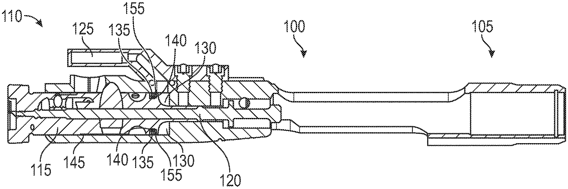
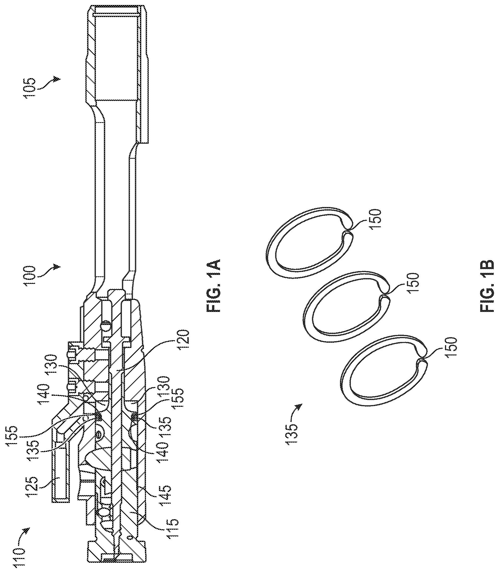
[0004] FIG. 1A shows a bolt carrier;
[0005] FIG. 1B shows a gas ring assembly;
[0006] FIG. 2A and 2B show a bolt having at least one vertical gas port with the gas ring assembly included;
[0007] FIG. 3A and 3B show a bolt having at least one vertical gas port with the gas ring assembly removed;
[0008] FIG. 4A, FIG. 4B, and FIG. 4C show a bolt having lateral gas ports; and
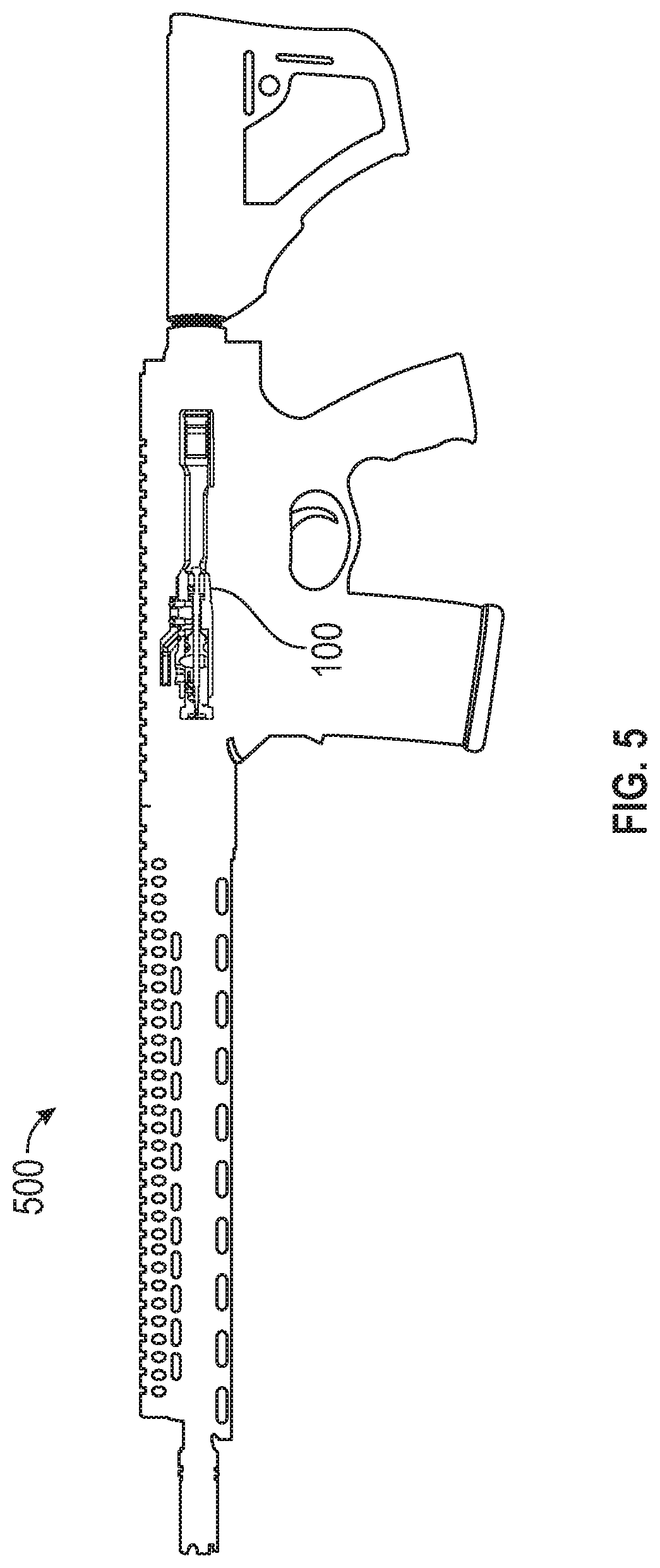
[0009] FIG. 5 shows a bolt carrier disposed in a rifle.
DETAILED DESCRIPTION
Overview
[0010] A bolt may be provided for a bolt carrier. The bolt carrier may comprise a gas inlet, a gas expansion chamber, a bolt bore, and the bolt. The gas expansion chamber that may receive a pressurized gas from the gas inlet. The bolt may be disposed in a bore in the bolt carrier. The bolt may comprise a gas ring groove, a gas ring assembly disposed in the gas ring groove, and at least one gas port. The gas ring assembly may be adjacent to the bolt bore. The at least one gas port may provide a pathway for the pressurized gas from the gas expansion chamber to a volume underneath the gas ring assembly to increase a radial sealing force between the gas ring assembly and the bolt bore.
[0011] Both the foregoing overview and the following example embodiments are examples and explanatory only, and should not be considered to restrict the disclosure's scope, as described and claimed. Further, features and/or variations may be provided in addition to those set forth herein. For example, embodiments of the disclosure may be directed to various feature combinations and sub-combinations described in the example embodiments.
EXAMPLE EMBODIMENTS
[0012] The following detailed description refers to the accompanying drawings. Wherever possible, the same reference numbers are used in the drawings and the following description to refer to the same or similar elements. While embodiments of the disclosure may be described, modifications, adaptations, and other implementations are possible. For example, substitutions, additions, or modifications may be made to the elements illustrated in the drawings, and the methods described herein may be modified by substituting, reordering, or adding stages to the disclosed methods. Accordingly, the following detailed description does not limit the disclosure. Instead, the proper scope of the disclosure is defined by the appended claims.
[0013] Embodiments of the disclosure may provide gas ports that may be used in conjunction with a bolt carrier of a semi-automatic, gas operated rifle for example. The gas ports may be lateral or vertical. Embodiments of the disclosure may include a bolt with gas ports that may allow propellant gas pressure to flow underneath a gas ring assembly to increase a radial sealing force by utilizing the propellant gas pressure. The radial sealing force may be produced due to gas ring assembly tension and an axial force on the gas ring assembly by the propellant gas pressure. Accordingly, consistent with embodiments of the disclosure, overall gas leakage may be reduced due to the increased seal thus increasing efficiency by allowing more force to be transferred axially. Due to this gas leakage reduction, the required gas may be reduced and or the initial tension of the gas ring assembly may be relaxed.
[0014] Lateral gas ports or vertical gas ports may be applied to gain the aforementioned advantage to provide a channel to the back side (i.e., underneath) of the gas ring assembly. Gas ports to allow gas to the backside of the gas ring assembly may take many shapes such as grooves or channels to allow the gas propellant flow. The gas ports may also comprise openings or cutouts of various shapes creating a path or a channel.
[0015] Consistent with embodiments of the disclosure, gas ports, both lateral and vertical, may be applied to any firearm operating system utilizing gas pressure that may come in contact with a gas ring (i.e., a gas ring assembly). Included are both a smaller rifle and a larger shotgun gas piston, both which employ gas rings for improved sealing to operate the firearm.
[0016] FIG. 1A shows a bolt carrier 100 consistent with embodiments of the disclosure. As shown in FIG. 1A, bolt carrier 100 may comprise a rear 105, a front 110, a bolt 115, a firing pin 120, a gas inlet 125, and a gas expansion chamber 130. Bolt 115 may comprise a gas ring assembly 135 and a gas ring groove 140. Bolt 115 may be disposed within a bolt bore 145 of bolt carrier 100. Consistent with embodiments of the disclosure, bolt 115 may include a gas port 155 described in greater detail below. During operation, pressurized propellant gas may enter gas inlet 125 and continue to gas expansion chamber 130. This may cause a firearm in which bolt carrier 100 is disposed to cycle (i.e., bolt carrier 100 extracts a spent casing and put a new round into the firearm's chamber).
[0017] FIG. 1B shows gas ring assembly 135 in more detail. As shown in FIG. 1B, gas ring assembly 135 may comprise one of more rings that may be disposed in gas ring groove 140. Consistent with embodiments of the disclosure, each of the one or more rings may include a gap 150. While FIG. 1B shows gas ring assembly 135 having three rings, embodiments of the disclosure are not so limited and may include any number of rings.
[0018] FIG. 2A and 2B show bolt 115 having at least one vertical gas port 155 with gas ring assembly 135 included in gas ring groove 140. FIG. 3A and 3B show bolt 115 having at least one vertical gas port 155 with gas ring assembly 135 removed. While FIG. 2A, FIG. 2B, FIG. 3A, and FIG. 3B show one vertical gas port 155, embodiments of the disclosure may include any number of gas ports 155 and are not limited to one.
[0019] Consistent with embodiments of the disclosure, gas port 155 may allow gas pressure from gas expansion chamber 130 to flow underneath gas ring assembly 135 to increase a radial sealing force against bolt bore 145 by utilizing the propellant gas pressure. The radial sealing force against bolt bore 145 may be produced due to tension of gas ring assembly 135 and an axial force on gas ring assembly 135 by propellant gas pressure. Accordingly, consistent with embodiments of the disclosure, overall gas leakage may be reduced due to the increased seal against bolt bore 145 thus increasing efficiency by allowing more force to be transferred axially. Due to this gas leakage reduction, the required gas may be reduced and or the initial tension of gas ring assembly 135 may be relaxed.
[0020] FIG. 4A, FIG. 4B, and FIG. 4C show bolt 115 having lateral gas ports 405. FIG. 4A shows an axial view of the rear of bolt 115. FIG. 4A shows four lateral gas ports 405, however, bolt 115 may have any number of lateral gas ports 405 and is not limited to four. FIG. 4B shows bolt 115 having lateral gas ports 405 with gas ring assembly 135 included in gas ring groove 140. FIG. 4C shows bolt 115 having lateral gas ports 405 with gas ring assembly 135 removed. Lateral gas ports 405 may be applied to gain the same advantage as vertical gas ports 155 as described above and may provide a more direct route to the back side (i.e., underneath) of gas ring assembly 135.
[0021] FIG. 5 shows a gas operated rifle 500. As shown in FIG. 5, bolt carrier 100 may be disposed in gas operated rifle 500. Gas operated rifle 500 may comprise a self-loading firearm that may comprise, for example, a semi-automatic rifle or a fully-automatic rifle. Consistent with embodiments of the disclosure, gas ports, both lateral and vertical, may be applied to any firearm operating system utilizing gas pressure that may come in contact with a gas ring (i.e., gas ring assembly 135). Included are both a smaller caliber rifle and a larger caliber shotgun with a gas piston system, both which employ gas rings for improved sealing to operate the firearm.
[0022] Embodiments of the present disclosure, for example, are described above with reference to block diagrams and/or operational illustrations of methods and systems, according to embodiments of the disclosure. The functions/acts noted in the blocks may occur out of the order as shown in any flowchart. For example, two blocks shown in succession may in fact be executed substantially concurrently or the blocks may sometimes be executed in the reverse order, depending upon the functionality/acts involved.
[0023] While the specification includes examples, the disclosure's scope is indicated by the following claims. Furthermore, while the specification has been described in language specific to structural features and/or methodological acts, the claims are not limited to the features or acts described above. Rather, the specific features and acts described above are disclosed as example for embodiments of the disclosure.
* * * * *
D00000
D00001
D00002
D00003
D00004
D00005
XML
uspto.report is an independent third-party trademark research tool that is not affiliated, endorsed, or sponsored by the United States Patent and Trademark Office (USPTO) or any other governmental organization. The information provided by uspto.report is based on publicly available data at the time of writing and is intended for informational purposes only.
While we strive to provide accurate and up-to-date information, we do not guarantee the accuracy, completeness, reliability, or suitability of the information displayed on this site. The use of this site is at your own risk. Any reliance you place on such information is therefore strictly at your own risk.
All official trademark data, including owner information, should be verified by visiting the official USPTO website at www.uspto.gov. This site is not intended to replace professional legal advice and should not be used as a substitute for consulting with a legal professional who is knowledgeable about trademark law.