Air-conditioning Outdoor Unit
NAKAGAWA; Hidetomo ; et al.
U.S. patent application number 16/620250 was filed with the patent office on 2020-05-21 for air-conditioning outdoor unit. The applicant listed for this patent is Mitsubishi Electric Corporation. Invention is credited to Hiroyuki JINNAI, Toshiyuk KUBONO, Hidetomo NAKAGAWA, Akinori SAKABE.
| Application Number | 20200158353 16/620250 |
| Document ID | / |
| Family ID | 65272163 |
| Filed Date | 2020-05-21 |


| United States Patent Application | 20200158353 |
| Kind Code | A1 |
| NAKAGAWA; Hidetomo ; et al. | May 21, 2020 |
AIR-CONDITIONING OUTDOOR UNIT
Abstract
An air-conditioning outdoor unit includes a compressor having a plurality of terminals each including a plurality of conductive pins. The outdoor unit includes a plurality of lead wire groups provided for the respective terminals and each including a plurality of lead wires connecting a control board to the plurality of conductive pins, and a plurality of different end connectors provided for the respective lead wire groups and each attached to an end portion of the lead wire group adjacent to the plurality of conductive pins. The lead wire groups are each connected by the end connector to the plurality of conductive pins and cut into two parts at a given point in a longitudinal direction. The two parts of the lead wire group are detachably coupled together at the given point by a pair of relay connectors. A length from the control board to the given point and a length from the given point to the end connector differ from one lead wire group to another.
| Inventors: | NAKAGAWA; Hidetomo; (Tokyo, JP) ; SAKABE; Akinori; (Tokyo, JP) ; KUBONO; Toshiyuk; (Tokyo, JP) ; JINNAI; Hiroyuki; (Tokyo, JP) | ||||||||||
| Applicant: |
|
||||||||||
|---|---|---|---|---|---|---|---|---|---|---|---|
| Family ID: | 65272163 | ||||||||||
| Appl. No.: | 16/620250 | ||||||||||
| Filed: | February 13, 2018 | ||||||||||
| PCT Filed: | February 13, 2018 | ||||||||||
| PCT NO: | PCT/JP2018/004829 | ||||||||||
| 371 Date: | December 6, 2019 |
| Current U.S. Class: | 1/1 |
| Current CPC Class: | F24F 13/20 20130101; F24F 1/08 20130101; F24F 11/89 20180101; F24F 11/88 20180101; F24F 1/20 20130101; F24F 1/22 20130101; F24F 2013/202 20130101 |
| International Class: | F24F 1/22 20060101 F24F001/22; F24F 11/89 20060101 F24F011/89; F24F 11/88 20060101 F24F011/88; F24F 1/08 20060101 F24F001/08 |
Foreign Application Data
| Date | Code | Application Number |
|---|---|---|
| Aug 8, 2017 | JP | PCT/JP2017/028712 |
Claims
1. An air-conditioning outdoor unit including a compressor having a plurality of terminals each including a plurality of conductive pins, the air-conditioning outdoor unit comprising: a plurality of lead wire groups provided for the respective terminals, the lead wire groups each including a plurality of lead wires connecting a control board to the plurality of conductive pins; and a plurality of different end connectors provided for the respective lead wire groups, the end connectors each being attached to an end portion of the lead wire group adjacent to the plurality of conductive pins, wherein the lead wire groups are each connected by the end connector to the plurality of conductive pins and cut into two parts at a given point in a longitudinal direction, the two parts of the lead wire group are detachably coupled together at the given point by a pair of relay connectors, and a length from the control board to the given point and a length from the given point to the end connector differ from one lead wire group to another.
2. The air-conditioning outdoor unit of claim 1, wherein the pair of relay connectors includes a male connector and a female connector, and placement of the male connector and the female connector differs from one lead wire group to another.
3. An air-conditioning outdoor unit including a compressor having a plurality of terminals each including a plurality of conductive pins, the air-conditioning outdoor unit comprising: a plurality of lead wire groups provided for the respective terminals, the lead wire groups each including a plurality of lead wires connecting a control board to the plurality of conductive pins; and a plurality of different end connectors provided for the respective lead wire groups, the end connectors each being attached to an end portion of the lead wire group adjacent to the plurality of conductive pins, wherein the lead wire groups are each connected by the end connector to the plurality of conductive pins and cut into two parts at a given point in a longitudinal direction, the two parts of the lead wire group are detachably coupled together at the given point by a pair of relay connectors; and the pair of relay connectors includes a male connector and a female connector, and placement of the male connector and the female connector differs from one lead wire group to another.
4. The air-conditioning outdoor unit of claim 1, wherein a combination of colors of the plurality of lead wires differs from one lead wire group to another, or a color of the plurality of lead wires all having a same color differs from one lead wire group to another.
Description
TECHNICAL FIELD
[0001] The present invention relates to an outdoor unit of an air-conditioning apparatus (hereinafter referred to as "air-conditioning outdoor unit") that prevents wiring mistakes in the assembly process.
BACKGROUND ART
[0002] A compressor included in an air-conditioning outdoor unit has a configuration where a container of the compressor contains an electric motor including a stator and a rotor, a compression mechanism configured to compress refrigerant, and a main shaft configured to transmit torque of the electric motor to the compression mechanism. The compressor of this type has a glass terminal that is disposed to pass through the container. The glass terminal is for supplying power from outside the container to the rotor of the electric motor (see, e.g., Patent Literature 1). In the technique disclosed in Patent Literature 1, a plurality of lead wires connected to the glass terminal are connected through a cluster block to respective conductive pins in the glass terminal. Cluster blocks of different colors are used here to prevent wiring mistakes.
CITATION LIST
Patent Literature
[0003] Patent Literature 1: Japanese Unexamined Patent Application Publication No. 2011-229221
SUMMARY OF INVENTION
Technical Problem
[0004] Even though the cluster blocks of different colors are used, it is still possible to connect the cluster blocks to any conductive pins. That is, the technique described above requires improvement because it is not good enough to reliably prevent wiring mistakes.
[0005] The present invention has been made to address the issue described above. An object of the present invention is to provide an air-conditioning outdoor unit that can physically prevent wiring mistakes.
Solution to Problem
[0006] An air-conditioning outdoor unit according to an embodiment of the present invention is an air-conditioning outdoor unit that includes a compressor having a plurality of terminals each including a plurality of conductive pins. The air-conditioning outdoor unit includes a plurality of lead wire groups provided for the respective terminals and each including a plurality of lead wires connecting a control board to the plurality of conductive pins, and a plurality of different end connectors provided for the respective lead wire groups and each attached to an end portion of the lead wire group adjacent to the plurality of conductive pins. The lead wire groups are each connected by the end connector to the plurality of conductive pins and cut into two parts at a given point in a longitudinal direction. The two parts of the lead wire group are detachably coupled together at the given point by a pair of relay connectors. A length from the control board to the given point and a length from the given point to the end connector differ from one lead wire group to another.
Advantageous Effects of Invention
[0007] The present invention makes it possible to physically prevent wiring mistakes.
BRIEF DESCRIPTION OF DRAWINGS
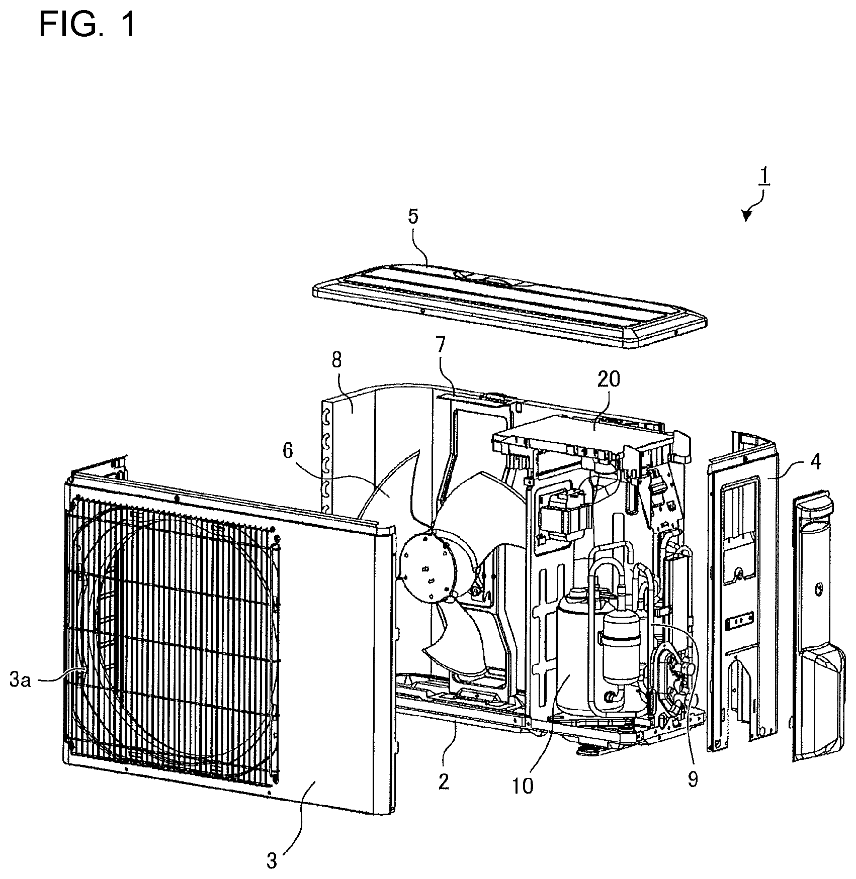
[0008] FIG. 1 is an exploded perspective view of an air-conditioning outdoor unit according to Embodiment 1 of the present invention.
[0009] FIG. 2 is a perspective view of an upper part of a compressor included in the air-conditioning outdoor unit according to Embodiment 1 of the present invention.
[0010] FIG. 3 is an explanatory diagram illustrating how the compressor and a control board included in the air-conditioning outdoor unit according to Embodiment 1 of the present invention are connected to each other.
[0011] FIG. 4 is an enlarged perspective view of the compressor illustrated in FIG. 3.
[0012] FIG. 5 is a diagram illustrating a modification example of the air-conditioning outdoor unit according to Embodiment 1 of the present invention.
[0013] FIG. 6 is an explanatory diagram illustrating how the compressor and the control board included in an air-conditioning outdoor unit according to Embodiment 2 of the present invention are connected to each other.
DESCRIPTION OF EMBODIMENTS
Embodiment 1
[0014] FIG. 1 is an exploded perspective view of an air-conditioning outdoor unit according to Embodiment 1 of the present invention.
[0015] As illustrated in FIG. 1, a housing of an air-conditioning outdoor unit 1 is composed of a bottom 2, a front shell 3 having an L-shape in plan view and extending from the front to the left side, an upper shell 5 forming a top face, and a side shell 4 forming the right side. The front shell 3 has an air outlet 3a opening at the front and an air inlet (not shown) opening on the left side. The housing contains, in the internal space above the bottom 2, a heat exchanger 8, a compressor 10, and a fan 6 that sends air into the heat exchanger 8. The heat exchanger 8 is disposed on the bottom 2 in such a manner as to cover substantially the entire back-side opening of the housing. The housing also contains a motor (not shown) that drives the fan 6, a motor mount 7 that secures the motor in place, and a connecting pipe 9. The connecting pipe 9 is configured to connect the heat exchanger 8 to the compressor 10. A control board 20 that controls the overall operation of the outdoor unit 1 is disposed above the compressor 10.
[0016] FIG. 2 is a perspective view of an upper part of the compressor included in the air-conditioning outdoor unit according to Embodiment 1 of the present invention.
[0017] The compressor 10 includes therein a compressor motor (not shown). The compressor motor is a three-phase motor that includes windings of three phases, U-phase, V-phase, and W-phase. The upper part of a container 10a of the compressor 10 has, at two points, a glass terminal 11a and a glass terminal 11b that pass through the container 10a of the compressor 10. Hereinafter, the glass terminal 11a and the glass terminal 11b may be collectively referred to as glass terminals 11. The glass terminals 11 are for supplying power from the control board 20 outside the container 10a to a stator of the compressor motor.
[0018] The glass terminal 11a includes three conductive pins 12. The three conductive pins 12 are each connected to one end portion of a corresponding one of the windings of U-phase, V-phase, and W-phase of the compressor motor in the container 10a. The glass terminal 11a thus includes a total of three conductive pins 12 for the respective U-phase, V-phase, and W-phase as a set. The glass terminal 11b similarly includes three conductive pins 13, and the three conductive pins 13 are each connected to one end portion of a corresponding one of the windings of U-phase, V-phase, and W-phase of the compressor motor in the container 10a. The glass terminal 11b thus includes a total of three conductive pins 13 for the respective U-phase, V-phase, and W-phase as a set. This configuration enables supply of power to the compressor motor.
[0019] The conductive pins 12 of the glass terminal 11a have a cylindrical pin shape. The conductive pins 13 of the glass terminal 11b are each composed of a cylindrical pin and a terminal connecting plate 13a attached to the cylindrical pin.
[0020] FIG. 3 is an explanatory diagram illustrating how the compressor and the control board included in the air-conditioning outdoor unit according to Embodiment 1 of the present invention are connected to each other. FIG. 4 is an enlarged perspective view of the compressor illustrated in FIG. 3.
[0021] A lead wire group 31 and a lead wire group 32, each including three lead wires, are each connected at one end portion thereof to the control board 20. A cluster block 14 serving as an end connector is attached to the other end portion of the lead wire group 31. The cluster block 14 is detachably connected to the conductive pins 12 of the glass terminal 11a. Flag-shaped terminals 15, serving as an end connector, are attached to the respective other end portions of the lead wires of the lead wire group 32. The flag-shaped terminals 15 are detachably connected to the respective conductive pins 13 of the glass terminal 11b. The configuration described above enables electrical connection between the control board 20 and the compressor 10. While not illustrated in detail in FIG. 3 and FIG. 4, the flag-shaped terminals 15 each have an insertion portion into which the terminal connecting plate 13a is inserted. Inserting the terminal connecting plate 13a into the insertion portion enables connection between the flag-shaped terminal 15 and the conductive pin 13.
[0022] The cluster block 14 is made of resin, and the flag-shaped terminals 15 are made of metal. As illustrated in FIG. 4, a terminal sleeve 16 is mounted on the flag-shaped terminal 15. To prevent fires caused by spark discharge resulting from poor contact between the conductive pin 13 and the flag-shaped terminal 15, a flame-resistant material is used to form the terminal sleeve 16. Although FIG. 4 only shows the terminal sleeve 16 mounted on one of the flag-shaped terminals 15, every flag-shaped terminal 15 has the terminal sleeve 16 mounted thereon.
[0023] The air-conditioning outdoor unit of Embodiment 1 is configured such that by a winding switching unit (not shown) on the control board 20, the connection of the compressor motor can be switched between a Y-connection and a A-connection. The Y-connection is a connection structure that provides better efficiency when the rotation speed of the compressor motor is low, whereas the A-connection is a connection structure that provides better efficiency when the rotation speed of the compressor motor is high. Specifically, the winding switching unit is formed by a relay. With the winding switching unit that switches the connection of the compressor motor in accordance with the operating condition as described above, the outdoor unit of Embodiment 1 can improve energy saving performance. The technique that allows the connection of the compressor motor to be switched between the Y-connection and the A-connection is a known technique, and the winding switching unit can be configured using this known technique.
[0024] In the type of compressors where no switching of the connection mode takes place, a total of three conductive pins that are connected to the respective windings of U-phase, V-phase, and W-phase of the compressor motor are arranged together in a single glass terminal. In the type of compressors where the connection mode is switched as in Embodiment 1, however, the windings of U-phase, V-phase, and W-phase of the compressor motor each need to be connected at both end portions of the winding to the winding switching unit of the control board 20. Since this requires a total of six conductive pins, two glass terminals, each having a set of three conductive pins connected to the U-phase, V-phase, and W-phase as described above, are arranged in the upper part of the container 10a.
[0025] The lead wire group 31 is determined, in the circuit configuration, to be connected to the glass terminal 11a. Similarly, the lead wire group 32 is determined, in the circuit configuration, to be connected to the glass terminal 11b. The lead wire group 31 is connected, on one side thereof adjacent to the control board 20, to the U-phase, V-phase, and W-phase through the winding switching unit, and is connected, on the other side thereof adjacent to the compressor 10, to the glass terminal 11a using the cluster block 14. The lead wire group 32 is connected, on one side thereof adjacent to the control board 20, to the U-phase, V-phase, and W-phase through the winding switching unit, and is connected, on the other side thereof adjacent to the compressor 10, to the glass terminal 11b using the flag-shaped terminals 15.
[0026] If the lead wire group 31 and the lead wire group 32 are too long, it is difficult to assemble them. Therefore, as illustrated in FIG. 3, the lead wire group 31 and the lead wire group 32 are each cut into two parts at a given point in the longitudinal direction. The lead wire group 31 has, at the given point, a pair of relay connectors 33 detachable from each other, and the two parts of the lead wire group 31 can be detachably coupled together by the pair of relay connectors 33. The pair of relay connectors 33 is composed of a male connector 33a and a female connector 33b.
[0027] The lead wire group 32 is similarly cut into two parts at a given point in the longitudinal direction. The lead wire group 32 has, at the given point, a pair of relay connectors 34 detachable from each other, and the two parts of the lead wire group 32 can be detachably coupled together by the pair of relay connectors 34. The pair of relay connectors 34 is composed of a male connector 34a and a female connector 34b.
[0028] If the lead wire group 31 and the lead wire group 32 are mistakenly connected to the glass terminal 11b and the glass terminal 11a, respectively, the switching between the Y-connection and the A-connection is not properly made. Embodiment 1 provides the following configuration to prevent such a wiring mistake. Of the two parts into which the lead wire group 31 is cut, one adjacent to the control board 20 is referred to as a lead wire group 31a, and the other adjacent to the compressor 10 is referred to as a lead wire group 31b. Similarly, of the two parts into which the lead wire group 32 is cut, one adjacent to the control board 20 is referred to as a lead wire group 32a, and the other adjacent to the compressor 10 is referred to as a lead wire group 32b.
[0029] The lead wire group 31 and the lead wire group 32 are now compared. Of the lead wire groups adjacent to the control board 20, the lead wire group 31a is longer in length than the lead wire group 32a. Of the lead wire groups adjacent to the compressor 10, the lead wire group 31b is shorter in length than the lead wire group 32b. That is, the lead wires on both sides of the pair of relay connectors 33 for one lead wire group differ in length from the lead wires on both sides of the pair of relay connectors 34 for the other lead wire group.
[0030] With this configuration, it is physically impossible to make wiring mistakes. That is, assume that the lead wire group 31b and the lead wire group 32b, which are adjacent to the compressor 10, are connected to the glass terminal 11a and the glass terminal 11b, respectively, and also assume that the coupling at the pair of relay connectors 33 and the coupling at the pair of relay connectors 34 are not yet made. The glass terminal 11a and the glass terminal 11b differ in the shape of the conductive pins 12 and the conductive pins 13. Therefore, when connecting the lead wire group 31b and the lead wire group 32b, which are adjacent to the compressor 10, to the glass terminals, the assembly worker can uniquely identify, at a glance, which of the cluster block 14 and the flag-shaped terminals 15 should be connected to which of the glass terminals. That is, as illustrated in FIG. 4, the cluster block 14 for the lead wire group 31b is connected to the glass terminal 11a, and the flag-shaped terminals 15 for the lead wire group 32b are connected to the glass terminal 11b.
[0031] Then assume, in this state, that the lead wire group 31a and the lead wire group 32a adjacent to the control board 20 are coupled, at the respective pairs of relay connectors, to the lead wire group 31b and the lead wire group 32b adjacent to the compressor 10. In this case, the male connector 33a for the lead wire group 31a can be coupled to the female connector 34b for the lead wire group 32b. However, the lead wire group 32a is too short to allow the male connector 34a to be coupled to the female connector 33b for the lead wire group 31a. Thus, a wiring mistake is prevented here.
[0032] As described above, in Embodiment 1, the lead wire groups are each cut into two parts at a given point in the longitudinal direction, and the two parts of the lead wire group are detachably coupled together at the given point. Then, the length from the control board 20 to the given point and the length from the given point to the end connector in one lead wire group differ from those in the other lead wire group. This makes it possible to physically prevent wiring mistakes.
[0033] Also, one lead wire group has the cluster block 14 as an end connector, whereas the other lead wire group has the flag-shaped terminals 15 as an end connector. Accordingly, the glass terminal 11a and the glass terminal 11b differ in the shape of the conductive pins. This can prevent the cluster block 14 and the flag-shaped terminals 15 from being connected to wrong glass terminals. Also, it is possible to uniquely identify at a glance which of the cluster block 14 and the flag-shaped terminals 15 should be connected to which of the glass terminals 11. This is effective in reducing the assembly time.
[0034] The terminal sleeves 16, which are used to prevent fires as described above, also serve the function of facilitating attaching and detaching of the flag-shaped terminals 15 to and from the conductive pins 13. That is, by varying at least the color or shape of the terminal sleeve 16 for each of the flag-shaped terminals 15, it is possible to prevent wiring mistakes in connecting the flag-shaped terminals 15 to the conductive pins 13.
[0035] The air-conditioning outdoor unit according to the present invention is not limited to the structure illustrated in the drawings mentioned above, and can be variously modified without departing from the scope of the present invention. For example, the lead wire group 31 and the lead wire group 32 may differ in the color of the lead wires, or may differ in the color of the pair of relay connectors. With reference to FIG. 5, a configuration will be described in which the colors of the lead wires differ from one lead wire group to another.
[0036] FIG. 5 is a diagram illustrating a modification example of the air-conditioning outdoor unit according to Embodiment 1 of the present invention. In FIG. 5, the lead wires of different colors are represented by lines of different thicknesses and types. In this modification example, each lead wire group has a different color combination of lead wires. That is, for example, the lead wire group 31 is formed by a combination of a black lead wire (thick solid line) 31A, a blue lead wire (thin solid line) 31B, and a red lead wire (thick dotted line) 31C, whereas the lead wire group 32 is formed by a combination of a black lead wire (thick solid line) 32A, a white lead wire (thin dot-and-dash line) 32B, and a red lead wire (thick dotted line) 32C.
[0037] Thus, by varying the color combination of lead wires for each lead wire group, it is possible to more visually identify a connection destination and prevent wiring mistakes. In this example, the color combination of lead wires is varied for each lead wire group. Alternatively, for example, the color of all the lead wires of the lead wire group 31 may be black and the color of all the lead wires of the lead wire group 32 may be red; that is, the color of lead wires all having the same color may be varied for each lead wire group.
Embodiment 2
[0038] Embodiment 2 differs from Embodiment 1 in wiring-mistake preventing structure provided at the pair of relay connectors. Differences between Embodiment 2 and Embodiment 1 will be primarily described here. Configurations not described in Embodiment 2 are the same as those in Embodiment 1.
[0039] FIG. 6 is an explanatory diagram illustrating how the compressor and the control board included in an air-conditioning outdoor unit according to Embodiment 2 of the present invention are connected to each other.
[0040] In Embodiment 1 described above, the lead wire group 31 and the lead wire group 32 have the pair of relay connectors 33 and the pair of relay connectors 34, respectively, that have the same placement of the male connector and the female connector. In Embodiment 2, on the other hand, the lead wire group 31 and the lead wire group 32 differ in the placement of the male connector and the female connector. That is, as illustrated in FIG. 6, the lead wire group 31 has the male connector and the female connector placed adjacent to the control board 20 and the compressor 10, respectively, whereas the lead wire group 32 has the male connector and the female connector placed adjacent to the compressor 10 and the control board 20, respectively.
[0041] With this configuration, it is impossible to make such a wiring mistake as connecting the lead wire group 31a to the lead wire group 32b connected to the glass terminal 11b, because their connectors are both male connectors. Also, by checking whether the relay connector is of the male or female type, it is easy to identify which of the lead wire group 31a and the lead wire group 32a should be connected to which of the lead wire group 31b and the lead wire group 32b. This can reduce assembly time and improve assembly performance.
[0042] As described above, in Embodiment 2, the lead wire group 31 and the lead wire group 32 differ in the placement of the male type and the female type in the pair of relay connectors. With this configuration, it is physically impossible to make a wrong connection in the pair of relay connectors, and it is possible to prevent wiring mistakes. Also, the connection destination can be visually identified easily, and improved assembly performance is achieved.
[0043] The configuration illustrated in FIG. 6 employs the technique of Embodiment 1, where the lengths on both sides of the pair of relay connectors 33 in one lead wire group differ from the lengths on both sides of the pair of relay connectors 34 in the other lead wire group. However, the feature of Embodiment 2 is basically that the lead wire group 31 and the lead wire group 32 differ in the placement of the male type and the female type in the relay connectors, and Embodiment 2 does not necessarily need to employ the technique of Embodiment 1. That is, the length from the control board 20 to a given point (where the lead wire group is cut) and the length from the given point to the end connector in one lead wire group may be the same as those in the other lead wire group. Even in this case, it is still possible, with the technique of Embodiment 2, to prevent wiring mistakes. The configuration of varying the color combination of three lead wires for each lead wire group, or the configuration of varying the color of three lead wires of the same color for each lead wire group, as described in the modification example of Embodiment 1, may be applied to Embodiment 2.
REFERENCE SIGNS LIST
[0044] 1 outdoor unit, 2 bottom, 3 front shell, 3a air outlet, 4 side shell, 5 upper shell, 6 fan, 7 motor mount, 8 heat exchanger, 9 connecting pipe, 10 compressor, 10a container, 11 glass terminal, 11a glass terminal, 11b glass terminal, 12 conductive pin, 13 conductive pin, 13a terminal connecting plate, 14 cluster block, 15 flag-shaped terminal, 16 terminal sleeve, 20 control board, 31 lead wire group, 31a lead wire group, 31b lead wire group, 32 lead wire group, 32a lead wire group, 32b lead wire group, 33 relay connector, 33a male connector, 33b female connector, 34 relay connector, 34a male connector, 34b female connector
* * * * *
D00000
D00001
D00002
D00003
D00004
D00005
D00006
XML
uspto.report is an independent third-party trademark research tool that is not affiliated, endorsed, or sponsored by the United States Patent and Trademark Office (USPTO) or any other governmental organization. The information provided by uspto.report is based on publicly available data at the time of writing and is intended for informational purposes only.
While we strive to provide accurate and up-to-date information, we do not guarantee the accuracy, completeness, reliability, or suitability of the information displayed on this site. The use of this site is at your own risk. Any reliance you place on such information is therefore strictly at your own risk.
All official trademark data, including owner information, should be verified by visiting the official USPTO website at www.uspto.gov. This site is not intended to replace professional legal advice and should not be used as a substitute for consulting with a legal professional who is knowledgeable about trademark law.