Exhaust Valve Device
INOUE; Katsufumi ; et al.
U.S. patent application number 16/631930 was filed with the patent office on 2020-05-21 for exhaust valve device. The applicant listed for this patent is Marelli Corporation. Invention is credited to Mizuki HAYASHIDA, Katsufumi INOUE, Yasunori KOZUKA, Youhei MAEZONO, Hiroaki MASUBUCHI, Shou UCHIDA.
| Application Number | 20200157988 16/631930 |
| Document ID | / |
| Family ID | 65015198 |
| Filed Date | 2020-05-21 |


View All Diagrams
| United States Patent Application | 20200157988 |
| Kind Code | A1 |
| INOUE; Katsufumi ; et al. | May 21, 2020 |
EXHAUST VALVE DEVICE
Abstract
An exhaust valve device includes a valve body, a valve seat, a support shaft, a coil spring, and a cushion member. The valve body is placed in an exhaust passage in a silencer, and configured to open and close the exhaust passage. The valve body abuts against the valve seat when the valve body is closed. The support shaft is fixed to the valve seat, and supports the valve body to be able to swing freely. The support shaft is inserted in the coil spring. The coil spring biases the valve body. The cushion member is interposed between the coil spring and the support shaft. The cushion member is rotatable relative to the support shaft.
| Inventors: | INOUE; Katsufumi; (Saitama-shi, Saitama, JP) ; MASUBUCHI; Hiroaki; (Saitama-shi, Saitama, JP) ; KOZUKA; Yasunori; (Saitama-shi, Saitama, JP) ; UCHIDA; Shou; (Saitama-shi, Saitama, JP) ; MAEZONO; Youhei; (Saitama-shi, Saitama, JP) ; HAYASHIDA; Mizuki; (Saitama-shi, Saitama, JP) | ||||||||||
| Applicant: |
|
||||||||||
|---|---|---|---|---|---|---|---|---|---|---|---|
| Family ID: | 65015198 | ||||||||||
| Appl. No.: | 16/631930 | ||||||||||
| Filed: | July 19, 2018 | ||||||||||
| PCT Filed: | July 19, 2018 | ||||||||||
| PCT NO: | PCT/JP2018/027128 | ||||||||||
| 371 Date: | January 17, 2020 |
| Current U.S. Class: | 1/1 |
| Current CPC Class: | F01N 13/00 20130101; F01N 1/163 20130101; F01N 2240/36 20130101; F01N 1/165 20130101; F01N 13/007 20130101 |
| International Class: | F01N 1/16 20060101 F01N001/16; F01N 13/00 20060101 F01N013/00 |
Foreign Application Data
| Date | Code | Application Number |
|---|---|---|
| Jul 20, 2017 | JP | 2017-140506 |
| Sep 12, 2017 | JP | 2017-174582 |
Claims
1. An exhaust valve device comprising: a valve body placed in an exhaust passage in a silencer, and configured to open and close the exhaust passage; a valve seat against which the valve body abuts when the valve body is closed; a support shaft fixed to the valve seat, and supporting the valve body to be able to swing freely; a coil spring in which the support shaft is inserted, the coil spring biasing the valve body; and a cushion member interposed between the coil spring and the support shaft, the cushion member being rotatable relative to the support shaft.
2. The exhaust valve device of claim 1, wherein the cushion member is shorter than the support shaft, and interposed between the coil spring and the support shaft at one end part in an axial direction of the coil spring, at which the coil spring abuts the valve body.
3. The exhaust valve device of claim 1, wherein the cushion member is placed between a part of the coil spring that biases the valve body, and the support shaft, and is provided integrally with the valve body, and when opening and closing the valve body, the cushion member swings together with the valve body.
4. The exhaust valve device of claim 3, wherein the cushion member is spaced apart from the support shaft by a prescribed clearance.
5. The exhaust valve device of claim 3, wherein the cushion member is integrated with the valve body.
6. The exhaust valve device of claim 5, wherein the cushion member includes a cylindrical part in which the support shaft is inserted, and a flange part that is welded to the valve body.
7. The exhaust valve device of claim 5, wherein the cushion member includes a semi-cylindrical part in which the support shaft is inserted, and a flange part that is welded to the valve body.
8. The exhaust valve device of claim 3, wherein the cushion member is formed integrally with the valve body.
9. The exhaust valve device of claim 1, further comprising an additional cushion member interposed between the coil spring and the support shaft, the additional cushion member being rotatable relative to the support shaft, wherein each of the cushion member and the additional cushion member is cylindrical.
10. The exhaust valve device of claim 9, wherein one of the cushion member and the additional cushion member is provided between a part at which the coil spring biases the valve body, and the support shaft.
11. The exhaust valve device of claim 9, wherein each of the cushion member and the additional cushion member is spaced apart from the support shaft by a prescribed clearance.
Description
CROSS-REFERENCE TO RELATED APPLICATIONS
[0001] This is a U.S. national phase application of PCT/JP2018/027128, filed on Jul. 19, 2018, which claims priority to Japanese Patent Application No. 2017-140506, filed on Jul. 20, 2017, and Japanese Patent Application No. 2017-174582, filed on Sep. 12, 2017. The entire disclosures of Japanese Patent Application Nos. 2017-140506 and 2017-174582, are hereby incorporated herein by reference.
TECHNICAL FIELD
[0002] The present invention relates to an exhaust valve device (exhaust control valve) that opens and closes an exhaust passage in a silencer according to the exhaust pressure of exhaust gas from an engine.
BACKGROUND ART
[0003] For example, for an intake control valve for which swirl is generated within a fuel chamber to improve the combustion state of a mixed gas in a multi-cylinder engine for an automobile, a rattle prevention device of a rotating shaft disclosed in Japanese Patent No. 4180760 is adopted. The rattle prevention device of a rotating shaft for an intake control valve disclosed in this reference comprises: a cushion member that can be expanded by a kerf provided in the center axis line direction and that is fitted to be rotatable on a small diameter part of the rotating shaft; and a spring member that pressure welds on the outer circumference surface of this cushion member, and presses the rotating shaft in the direction perpendicular to the center axis line. Also, with this rattle prevention device of a rotating shaft for an intake control valve a protrusion that extends in the center axis line direction is provided projecting outward on the cushion member, and the kerf is formed on the protrusion.
[0004] Also, when the spring member is set by pressure welding on the cushion member and the spring member contacts the protrusion, the cushion member rotates with a slight imbalance of the spring load that acts on the protrusion, and the kerf moves to a position that does not contact the spring member. Also, when the cushion member rotates according to the rotation of the rotating shaft, the protrusion contacts the spring member, inhibiting further rotation, and preventing contact of the kerf and the spring member. As a result of these, the cushion member is expanded by the spring member, and wear due to direct contact of the rotating shaft and the spring member is prevented.
SUMMARY
[0005] However, with the conventional control valve, since the cushion member is fitted to be rotatable on the small diameter part of the rotating shaft, with the cushion member, relative movement occurs with respect to the spring member, and friction occurs with the spring member, so it was difficult to sufficiently suppress wear of the spring member.
[0006] In light of that, the purpose of the present invention is to address the problems noted above.
[0007] An exhaust valve device of one mode of the present invention comprises: a valve body that is placed in an exhaust passage in a silencer, and that opens and closes the exhaust passage; a valve seat that the valve body abuts when the valve body is closed; a support shaft that is fixed to the valve seat, and that supports the valve body to be able to swing freely; a coil spring in which the support shaft is inserted, that biases the valve body; and a cushion member that is interposed between the coil spring and the support shaft. The cushion member is rotatable relative to the support shaft.
[0008] With the exhaust valve device of one mode of the invention of the present application, it is possible to more reliably suppress wear of the coil spring.
BRIEF DESCRIPTION OF THE DRAWINGS
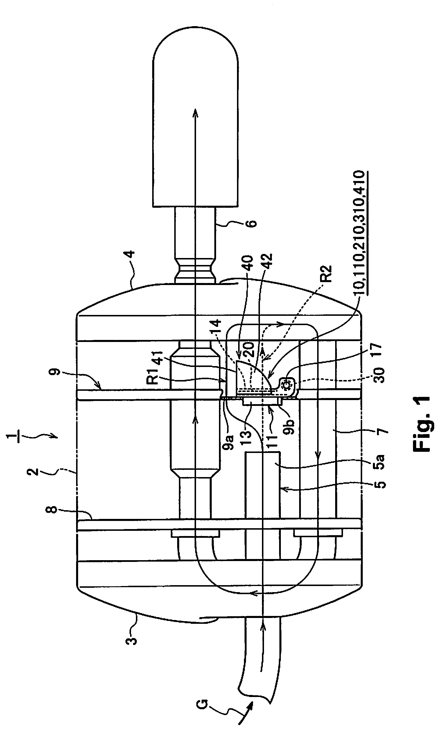
[0009] FIG. 1 is a schematic block diagram of a silencer built into an exhaust valve device of a first embodiment of the present invention.
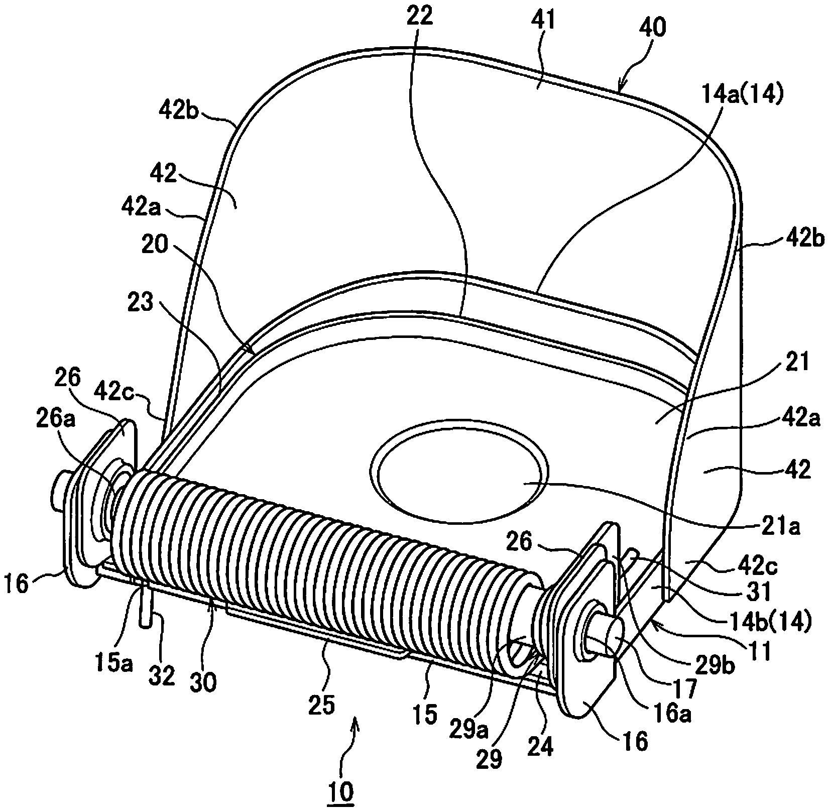
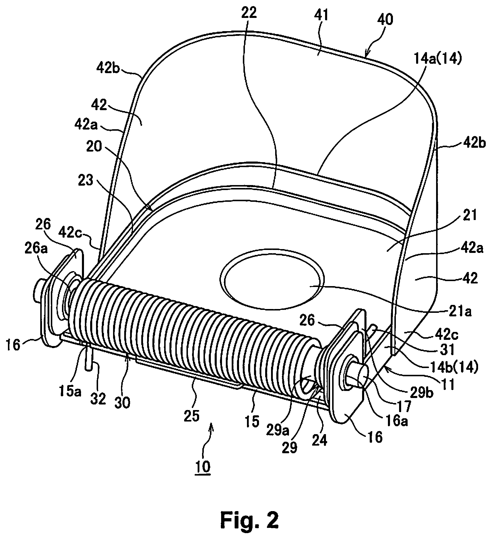
[0010] FIG. 2 is a perspective view of the exhaust valve device of the first embodiment seen from the valve body side.
[0011] FIG. 3 is an exploded perspective view of the exhaust valve device of the first embodiment.
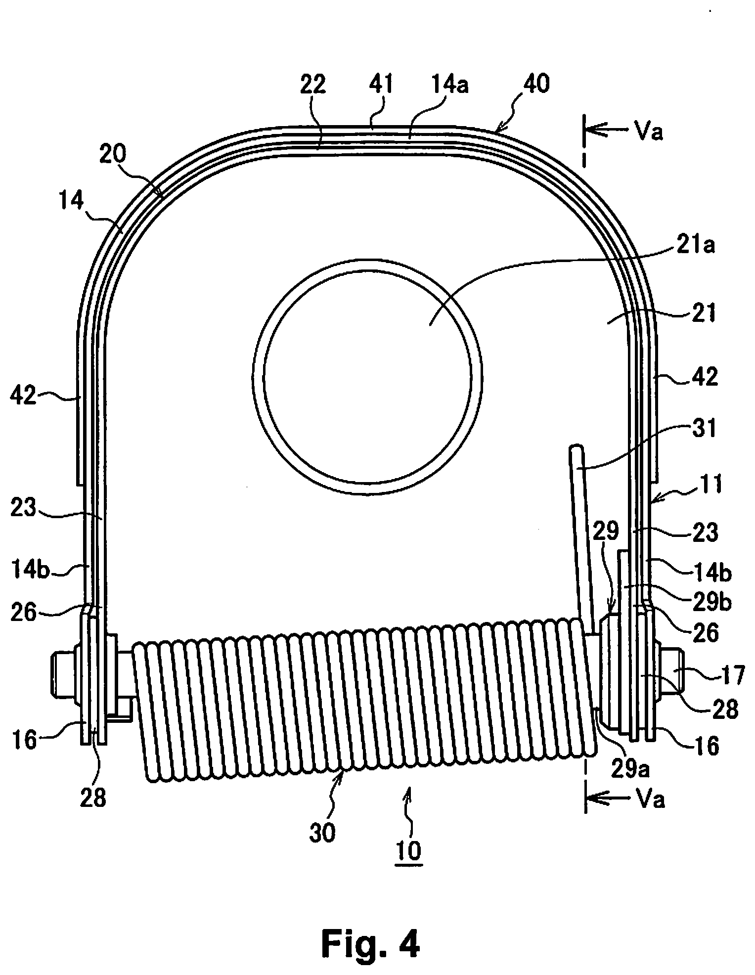
[0012] FIG. 4 is a rear view of the exhaust valve device of the first embodiment.
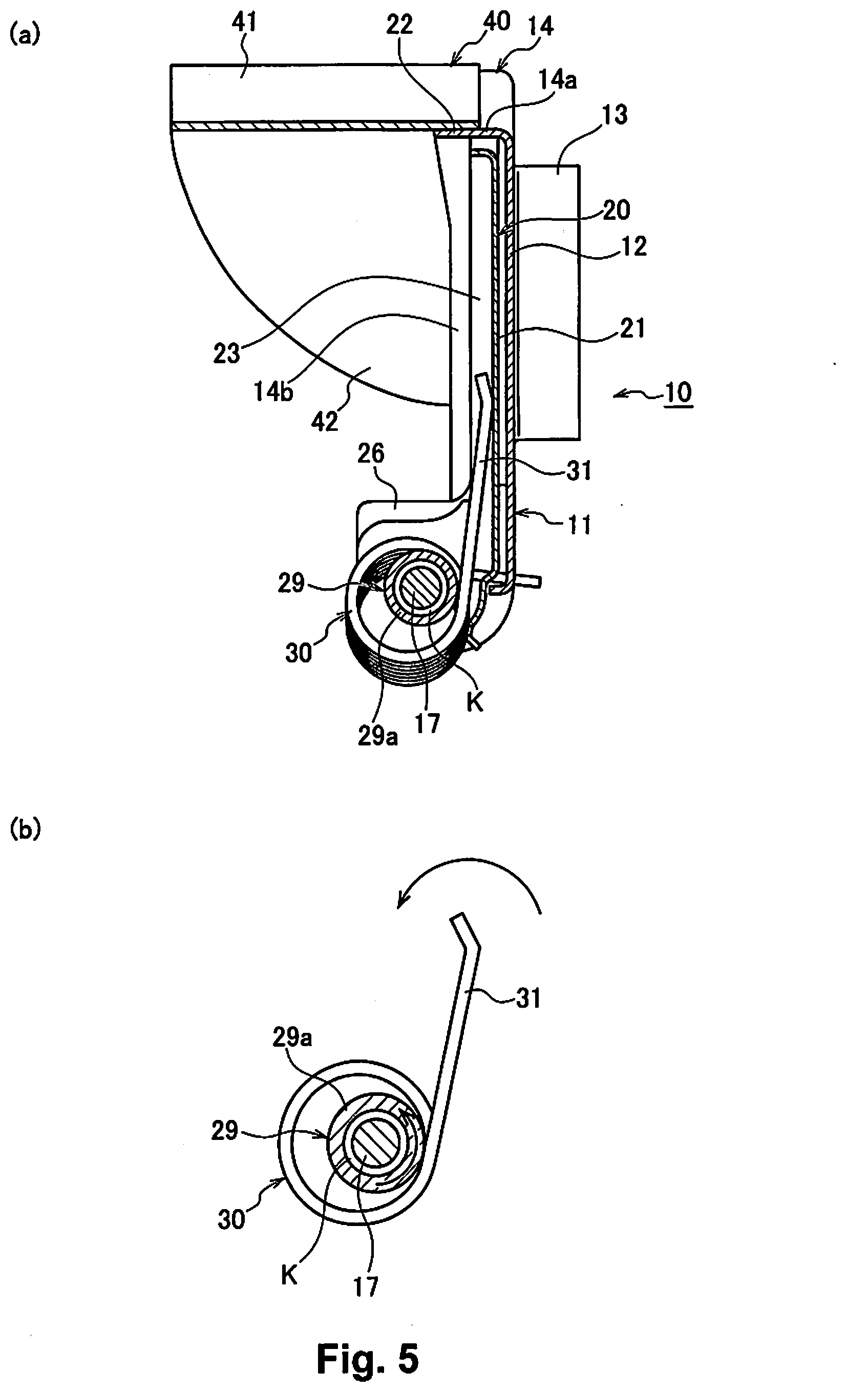
[0013] FIG. 5 includes a diagram (a), which is a cross section view along line Va-Va in FIG. 4, and a diagram (b), which is an explanatory drawing showing the relationship between a support shaft that swings the valve body, a coil spring, and a collar member.
[0014] FIG. 6 is a perspective view of the exhaust valve device of a second embodiment of the present invention seen from the valve body side.
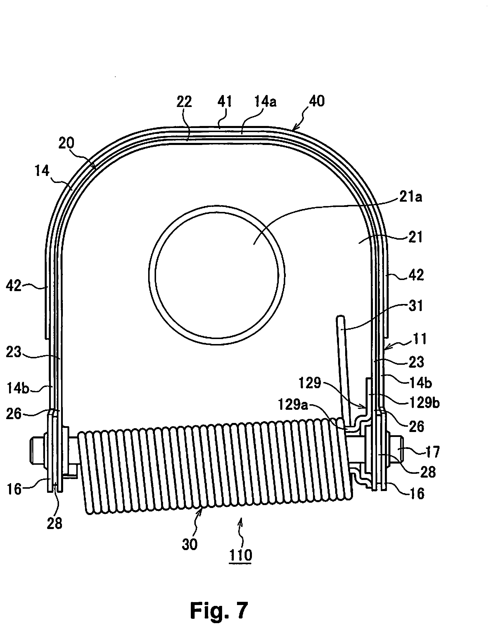
[0015] FIG. 7 is a rear view of the exhaust valve device of the second embodiment.
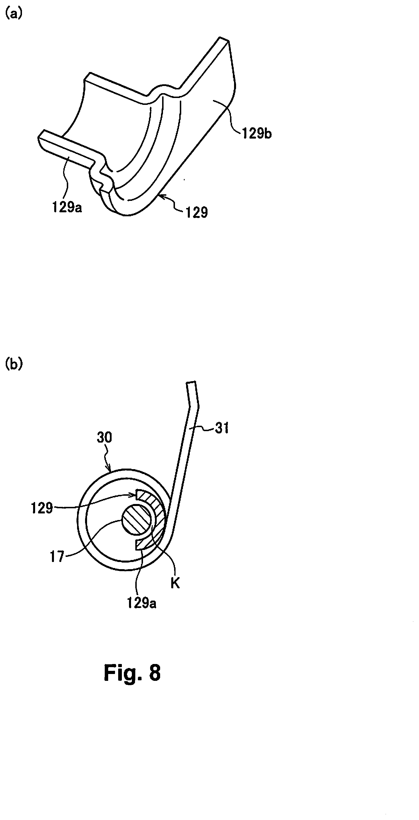
[0016] FIG. 8 includes a diagram (a), which is a perspective view of the collar member of the exhaust valve device of the second embodiment, and a diagram (b), which is an explanatory drawing showing the relationship between the support shaft that swings the valve body, the coil spring, and the collar member of that same exhaust valve device.
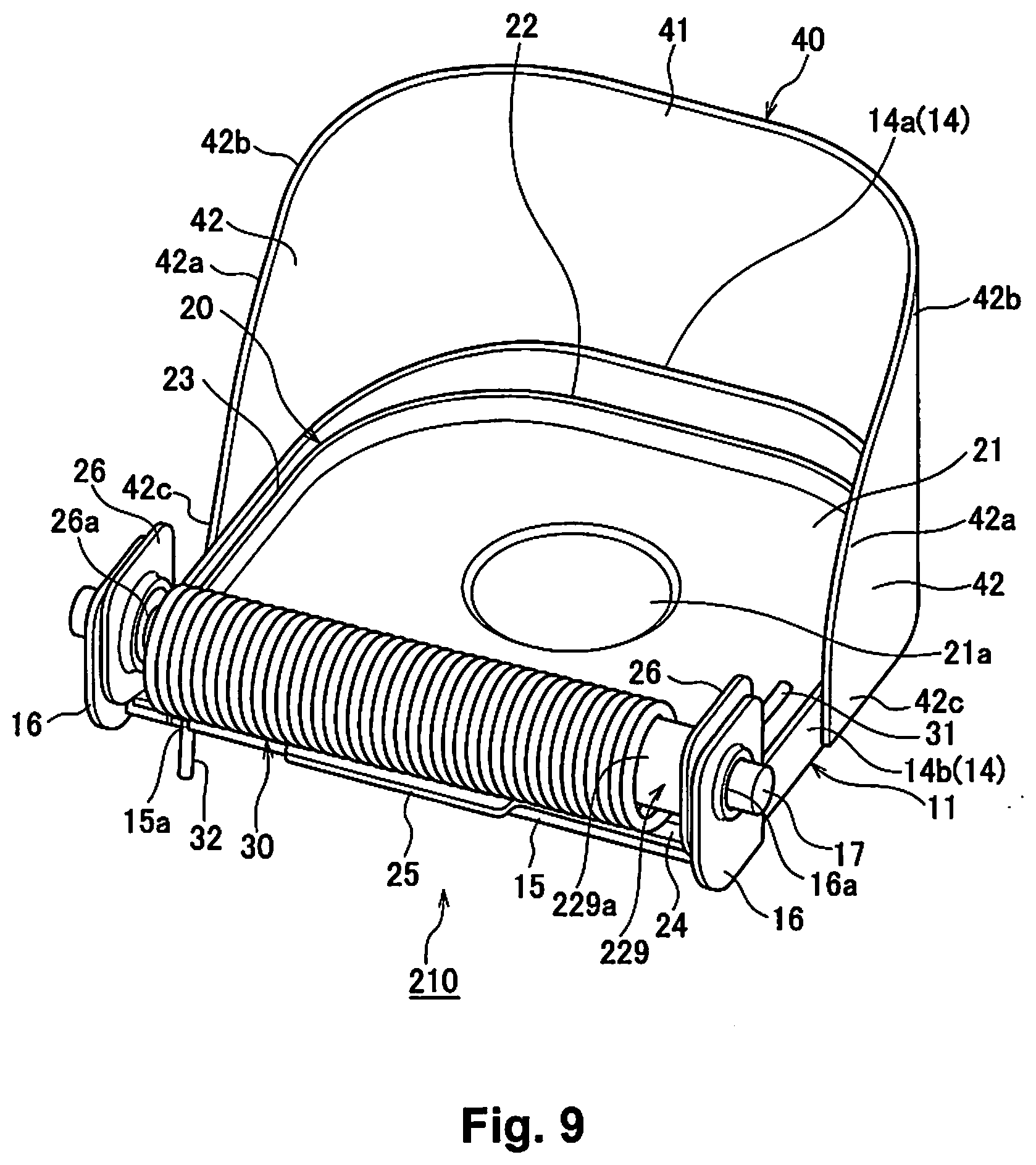
[0017] FIG. 9 is a perspective view of the exhaust valve device of a third embodiment of the present invention seen from the valve body side.
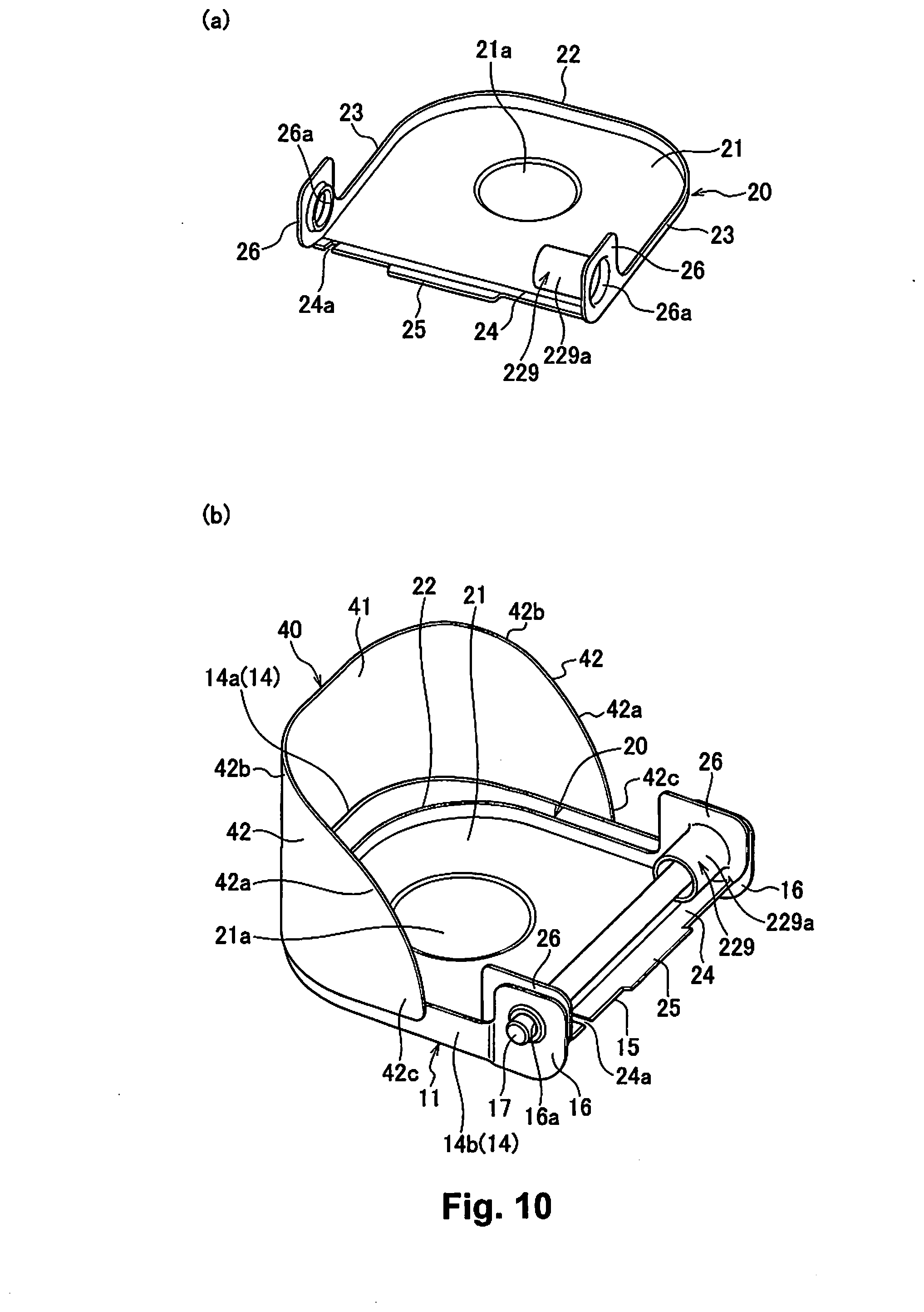
[0018] FIG. 10 includes a diagram (a), which is a perspective view of the valve body of the exhaust valve device of the third embodiment, and a diagram (b), which is a perspective view showing the state with the valve body of the third embodiment mounted on the support shaft.
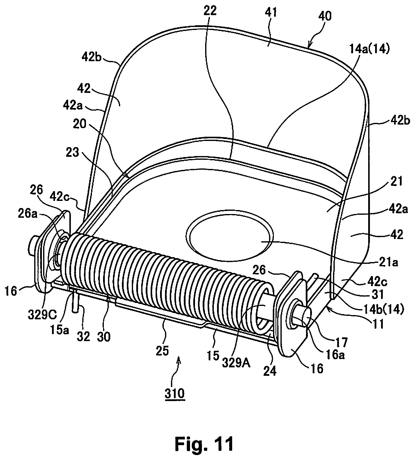
[0019] FIG. 11 is a perspective view of the exhaust valve device of a fourth embodiment seen from the valve body side.
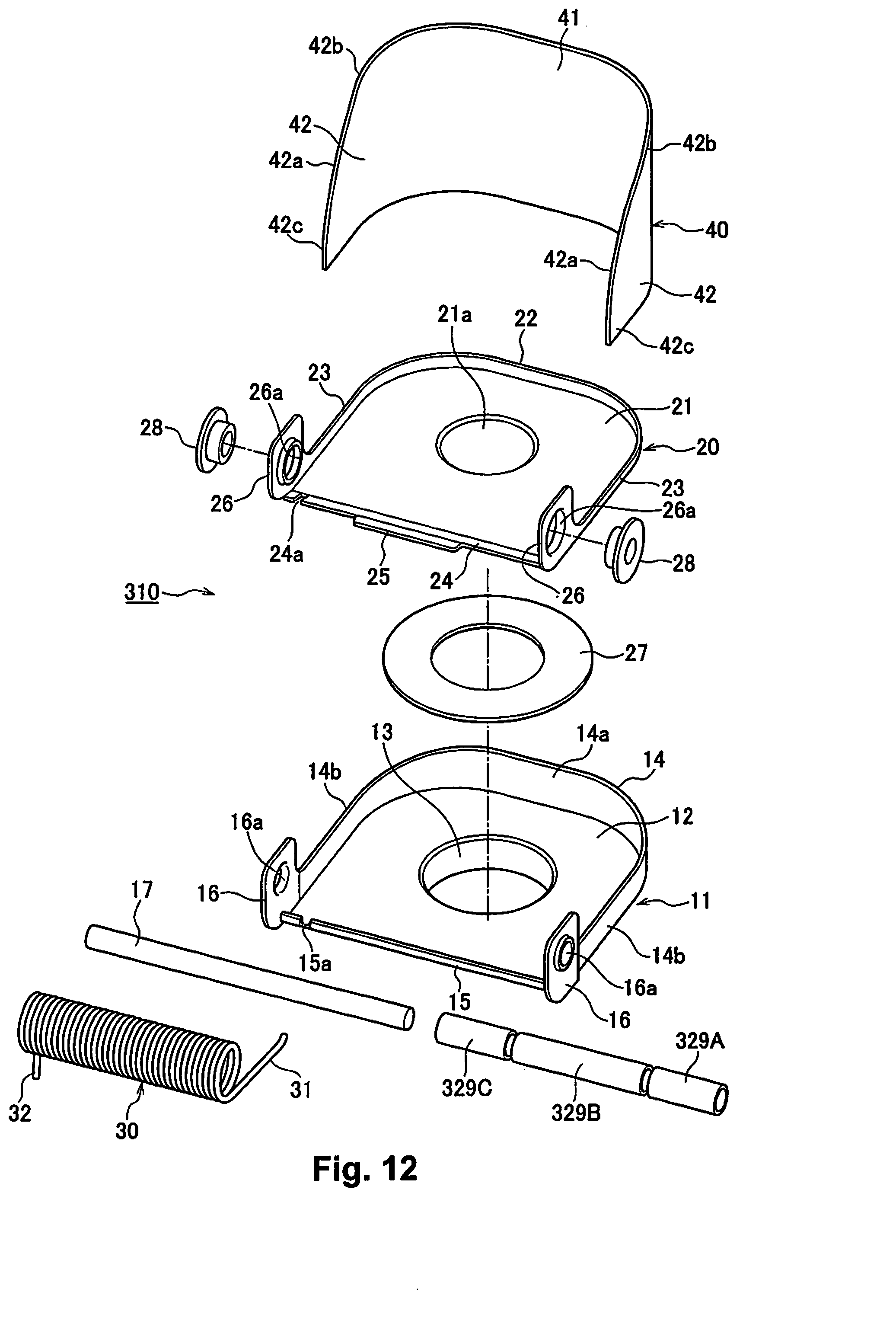
[0020] FIG. 12 is an exploded perspective view of the exhaust valve device of the fourth embodiment.
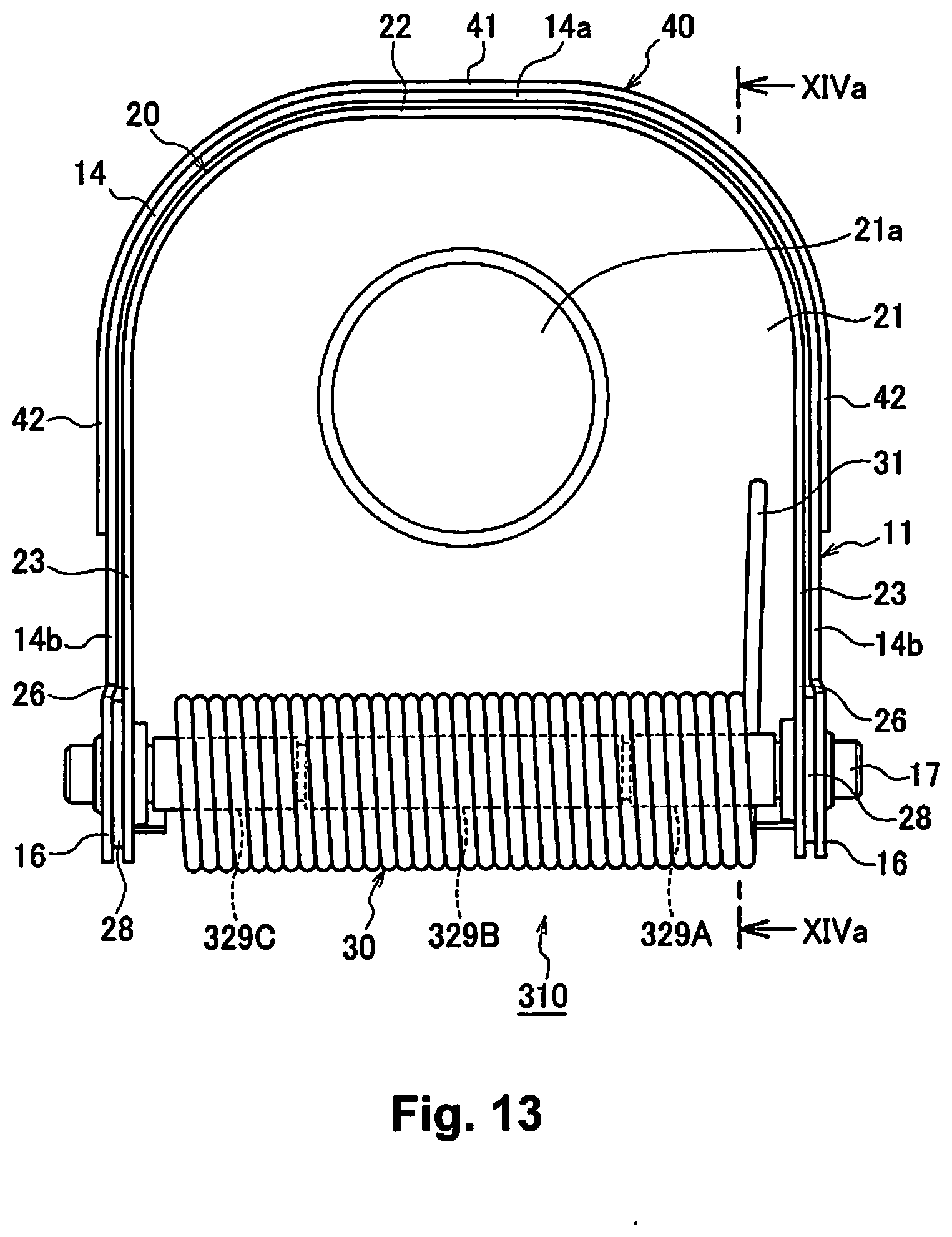
[0021] FIG. 13 is a rear view of the exhaust valve device of the fourth embodiment.
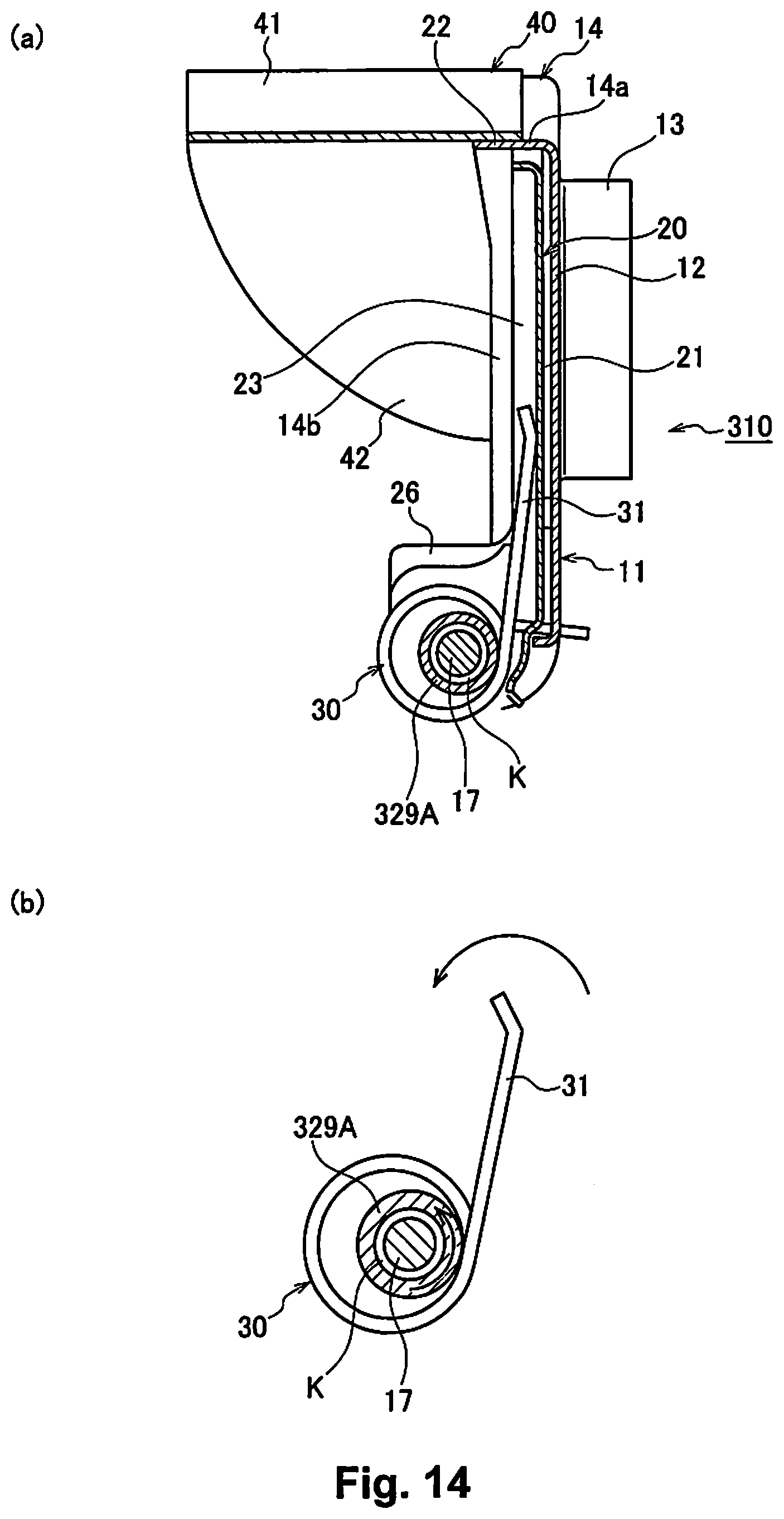
[0022] FIG. 14 includes a diagram (a), which is a cross section view along line XIVa-XIVa in FIG. 13 of the fourth embodiment, and a diagram (b), which is an explanatory drawing showing the relationship between the support shaft, the coil spring, and the collar member of the valve body of the fourth embodiment.
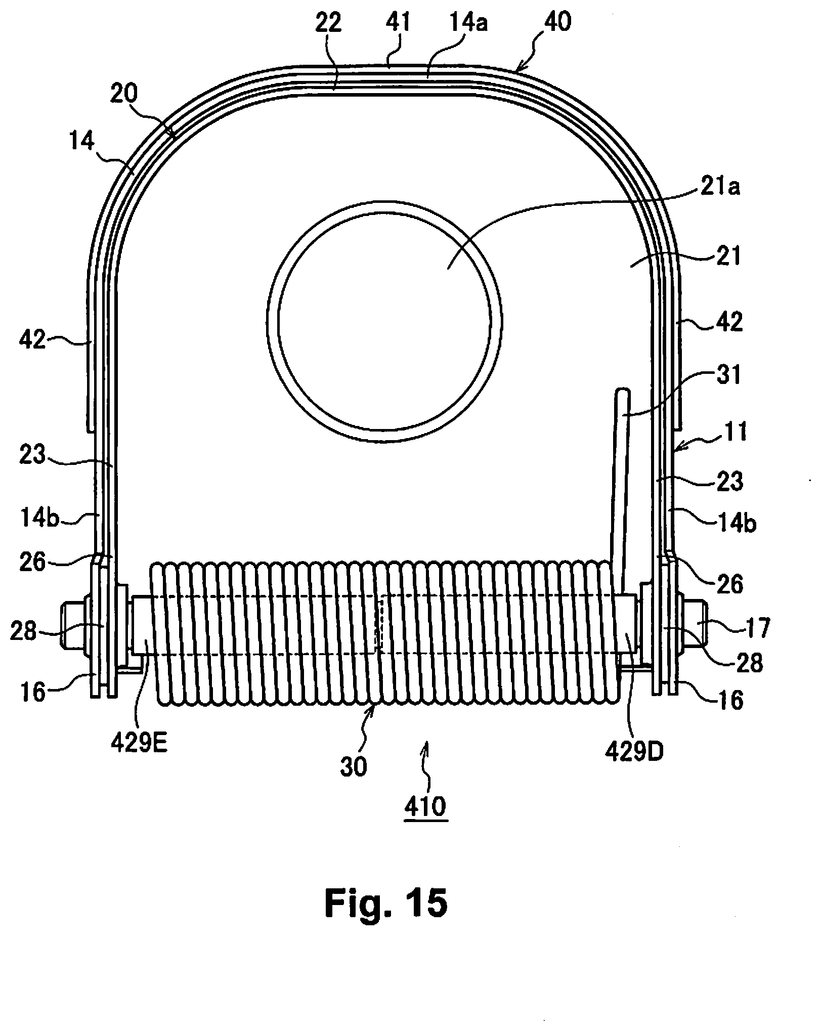
[0023] FIG. 15 is a rear view of the exhaust valve device of a fifth embodiment of the present invention.
DETAILED DESCRIPTION OF EMBODIMENTS
[0024] Following, embodiments of the present invention are explained based on the drawings.
[0025] Here, for convenience of explanation, the direction of the flow of exhaust gas from upstream to downstream (direction shown by arrow R2 in FIG. 1) is used as the front-back direction. Also, one prescribed direction orthogonal to the front-back direction is used as the vertical direction, and the direction orthogonal to the front-back direction and the vertical direction is the horizontal direction (lateral direction).
First Embodiment
[0026] FIG. 1 is a schematic block diagram of a silencer with an exhaust valve device of a first embodiment of the present invention built in, FIG. 2 is a perspective view of the exhaust valve device seen from the valve body side, FIG. 3 is an exploded perspective view of the same exhaust valve device, FIG. 4 is a rear view of the exhaust valve device, FIG. 5(a) is a cross section view along line Va-Va in FIG. 4, and FIG. 5(b) is an explanatory drawing showing the relationship between a support shaft that swings the valve body, a coil spring, and a collar member.
[0027] As shown in FIG. 1, an exhaust valve device 10 is attached to a through hole 9b which is one of a pair of through holes 9a, 9b formed on a baffle plate (partition plate 9) that partitions the inside of a silencer (muffler) 1. This exhaust valve device 10 opens and closes the through hole 9b which becomes an exhaust passage in the silencer 1 according to the exhaust pressure of an exhaust gas G from an engine (not illustrated).
[0028] As shown in FIG. 1, with the silencer 1, a silencer body (muffler body) is configured by a substantially cylindrical outer shell 2, and outer plates 3, 4 that block both front-back end openings of this outer shell 2. This silencer 1 muffles and cools the exhaust discharge sound and the high temperature exhaust gas G generated from the engine (not illustrated) using an inlet pipe (exhaust pipe) 5 provided in the interior, an outlet pipe 6, an inner pipe 7, and a pair of baffle plates (partition plates) 8, 9 in plate form.
[0029] As shown in FIG. 1 to FIG. 3, the exhaust valve device 10 is configured by: a valve seat 11 made of metal that is fixed by spot welding, etc., to the through hole 9b of the baffle plate 9; a valve body 20 made of metal that opens and closes a cylindrical part (inlet pipe) 13 that becomes the exhaust passage of this valve seat 11; a torsion coil spring (coil spring) 30 made of metal that biases this valve body 20 in the closing direction; and an outer cylinder 40 made of metal that is fixed by spot welding, etc., to an end part 14 of the downstream side of the flow direction of the exhaust gas G of the valve seat 11.
[0030] As shown in FIG. 2 and FIG. 3, the valve seat 11 comprises: a flat plate part 12 that is substantially square for which both top corner sides are arc shaped; a cylindrical part 13 that is formed integrally projecting in cylinder form at the front-back center of this flat plate part 12; and an end part 14 having a top end part 14a and both side end parts 14b, 14b formed bent integrally further to the rear than the top end edge and both side end edges of the flat plate part 12.
[0031] On the bottom end edge of the flat plate part 12 of the valve seat 11, a stopper receiving part 15 that regulates swinging of the valve body 20 is formed bent integrally to the rear. On this stopper receiving part 15, a notch part 15a is formed near one side end part 14b. Also, on the bottom side of both side end parts 14b, 14b of the valve seat 11, a pair of flanges 16, 16 having a shaft through hole 16a at the center is integrally formed. A support shaft 17 penetrates each shaft through hole 16a of this pair of flanges 16, 16. The support shaft 17 that penetrates each shaft through hole 16a of this pair of flanges 16, 16 has both end sides fixed by welding, etc., to the pair of flanges 16, 16.
[0032] As shown in FIG. 2 and FIG. 3, the valve body 20 comprises: a flat plate part 21 that is substantially square with both top corner sides being arc shaped; and a top part 22 and both side parts 23, 23 formed bent integrally further to the rear than the top end edge and both side end edges of this flat plate part 21.
[0033] At the bottom end edge of the flat plate part 21 of the valve body 20, an inclined piece 24 is formed bent inclined to the rear. At the center of this inclined piece 24, a stopper 25 that abuts the stopper receiving part 15 of the valve seat 11 is formed integrally projecting. The stopper 25 of this valve body 20 abuts the stopper receiving part 15 of the valve seat 11, and the angle up to the angle at which the valve body 20 swings is regulated is the prescribed opening degree of the valve body 20.
[0034] Also, close to one side part 23 of the inclined piece 24, a notch part 24a is formed. Furthermore, at the bottom side of both side parts 23, 23 of the valve body 20, a pair of flanges 26, 26 having a shaft through hole 26a at the center is integrally formed. The support shaft 17 supporting the valve body 20 to swing freely on the valve seat 11 is penetrated inside each shaft through hole 26a of this pair of flanges 26, 26.
[0035] Furthermore, at the center of the flat plate part 21 of the valve body 20, a circular convex part 21a is formed integrally projecting at the front surface side, and around this circular convex part 21a of the front surface of the flat plate part 21, a heat resistant, annular plate shaped cushioning mat 27 is fixed by spot welding, etc. When the valve body 20 is closed, the flat plate part 21 of the valve body 20 is made to abut the flat plate part 12 of the valve seat 11 without gaps with the cushioning mat 27 interposed. Also, annular bushes 28 are made to be penetrated by the support shaft 17 between each of the pair of flanges 16, 16 of the valve seat 11 and the pair of flanges 26, 26 of the valve body 20. The valve body 20 is axially supported to swing freely on the support shaft 17 with this pair of bushes 28, 28 interposed.
[0036] Also, as shown in FIG. 2 and FIG. 4, on the inner surface side of one flange 26 (the one that is not the flange 26 on the side on which the notch part 24a is formed) of the valve body 20, a collar member (cushion member) 29 made of metal is fixed in integral form. Specifically, the collar member 29 comprises: a cylinder shaped cylindrical part 29a through which the support shaft 17 is inserted, and a plate shaped flange part 29b that is integrally formed perpendicular to the axial direction at one end side of this cylindrical part 29a. This plate shaped flange part 29b is welded to one flange 26 of the valve body 20 using welding, etc., to be integrated. With the first embodiment, the valve body 20 and the collar member 29 are integrated using welding, but as long as the configuration has the valve body 20 and the collar member 29 integrated so as to swing together, there is no particular restriction, and for example, it is also possible to be integrated using press molding, etc. Also, as shown in FIG. 5(a), the collar member 29 is installed between the part of one end 31 of the torsion coil spring 30 that biases the valve body 20, and the support shaft 17. In other words, at one end part that is the side at which the torsion coil spring 30 abuts the valve body 20 in the axial direction of the torsion coil spring 30 (end part of one end 31 side in the axial direction of the torsion coil spring 30), the collar member 29 is interposed between the torsion coil spring 30 and the support shaft 17. Also, the cylindrical part 29a of the collar member 29, with the torsion coil spring 30 externally mounted, has a prescribed clearance K with the support shaft 17. Also, during opening and closing of the valve body 20, the collar member 29 is made to swing together with the valve body 20.
[0037] As shown in FIG. 2 and FIG. 4, the torsion coil spring 30 is mounted around the support shaft 17, and its one end 31 side is abutted and locked to the rear surface of the plate shaped part 21 of the valve body 20, and the other end 32 is locked in the notch part 15a of the stopper receiving part 15 of the valve seat 11. By doing this, Biasing is done on the valve seat 11 in the direction of closing the valve body 20.
[0038] As shown in FIG. 2 and FIG. 3, the outer cylinder 40 is provided extending to the downstream side of the flow direction of the exhaust gas G from the end part 14 of the valve seat 11. Also, comprised are an upper wall (ceiling wall) 41 that covers the upper end part 14a of the end part 14 of the valve seat 11, and both side walls 42, 42 that cover both side end parts 14b, 14b of the end part 14 of the valve seat 11 for which a center part 42a of the downstream side end part in the flow direction of the exhaust gas G projects in an arc shape, forming substantially an inverted U shaped plate, and being fixed to the end part 14 of the valve seat 11 by spot welding, etc.
[0039] When the valve body 20 is a prescribed opening degree, the upper wall 41 of the outer cylinder 40 and each arc shaped center part 42a of both side wall parts 42, 42 are made to respectively cover the top part 22 and both side parts 23, 23 of the valve body 20 open in resistance to the biasing force of the torsion coil spring 30. The prescribed opening degree of the valve body 20 is the angle at which the valve body 20 swings when the exhaust pressure of the exhaust gas G is at maximum, and for example, is set to maximum 45.degree.. By doing this, when the valve body 20 is opened, the periphery of the valve body 20 is covered by the outer cylinder 40, so the opening degree of the valve body 20 increases, and it is made possible to obtain a low back pressure effect.
[0040] With the exhaust valve device 10 of the first embodiment, when at low engine speed, the exhaust pressure of the exhaust gas G that flows inside the silencer 1 is low, so the valve body 20 of the exhaust valve device 10 is closed. When this valve body 20 is closed, the exhaust gas G flows as shown by the arrow R1 in FIG. 1 inside the silencer 1, and with the intermediate route of the inner pipe 7 from an end part 5a of the inlet pipe 5, passes through the through hole 9a of the baffle plate 9, and the noise level is reduced by the hole diameter (ventilation resistance) of this through hole 9a.
[0041] Also, in a medium to high rotation speed when the rotation speed of the engine exceeds a prescribed low speed rotation range, and the exhaust pressure of the exhaust gas G exceeds the biasing force by the elasticity of the torsion coil spring 30, the valve body 20 of the exhaust valve device 10 opens in resistance to the elastic biasing force of the torsion coil spring 30. In this case, with the intermediate route of the inner pipe 7 from the end part 5a of the inlet pipe 5, the flow of the exhaust gas G becomes two flows: the flow shown by arrow R1 in FIG. 1 for which the flow of the exhaust gas G passes through the through hole 9a of the baffle plate 9, and the flow shown by arrow R2 in FIG. 1 for which it passes through the cylindrical part 13 (the through hole 9b of the baffle plate 9) of the valve seat 11 of the exhaust valve device 10. In other words, the cross section area in which the exhaust gas G flows increases, and the ventilation resistance decreases.
[0042] The support shaft 17 that penetrates between the pair of flanges 16, 16 of the valve seat 11 supports the pair of flanges 26, 26 of the valve body 20 to swing freely with the bushes 28 interposed. Furthermore, the torsion coil spring 30 that biases the valve body 20 in the closing direction is externally mounted on this support shaft 17. For this reason, the exhaust valve device 10 can reduce the number of components by that amount, and it is possible to simplify the overall structure.
[0043] Also, as shown in FIG. 2 and FIGS. 5 (a) and (b), the plate shaped flange part 29b of the collar member 29 for which the cylindrical part 29a is interposed between the support shaft 17 and the torsion coil spring 30 is fixed by welding, etc., to the inner surface side of one flange 26 of the bottom side of both side parts 23, 23 of the valve body 20. Also, the collar member 29, for which the cylindrical part 29a having a larger diameter than the diameter of the support shaft 17 contacts the torsion coil spring 30, is made to swing together with the valve body 20. As a result of this, it is possible to easily, reliably, and at low cost, prevent wear of the torsion coil spring 30, and in particular wear of the one end 31 side of the torsion coil spring 30.
[0044] Furthermore, by providing on the valve seat 11 the stopper receiving part 15 that regulates swinging of the valve body 20, it is possible to make the opening degree (swing angle) regulated by the stopper 25 of the valve body 20 contacting the stopper receiving part 15 of the valve seat 11 be the maximum angle.
Second Embodiment
[0045] FIG. 6 is a perspective view of the exhaust valve device of a second embodiment of the present invention seen from the valve body side, FIG. 7 is a rear view of the same exhaust valve device, FIG. 8(a) is a perspective view of the collar member of the same exhaust valve device, and FIG. 8(b) is an explanatory drawing showing the relationship of the support shaft that swings the valve body of the same exhaust valve device, the coil spring, and the collar member.
[0046] As shown in FIG. 6 to FIG. 8, with an exhaust valve device 110 of this second embodiment, a collar member (cushion member) 129 comprising a semi-cylindrical part 129a in which the support shaft 17 is inserted, and a flange part 129b as a weld part is the point that differs from the first embodiment. The remainder of the configuration is the same as that of the first embodiment, so a detailed explanation is omitted for the same configuration parts and the same code numbers as those of the first embodiment.
[0047] With the exhaust valve device 110 of the second embodiment, as shown in FIG. 6 and FIG. 8(b), the plate shaped flange part 129b of the collar member 129 for which the semi-cylindrical part 129a is interposed between the support shaft 17 and the torsion coil spring 30 is fixed integrally by welding, etc., to the inner surface side of one flange 26 of the bottom side of both side parts 23, 23 of the valve body 20, and the collar member 129 for which the semi-cylindrical part 129a with a diameter larger than the diameter of the support shaft 17 contacts the torsion coil spring 30 is made to swing together with the valve body 20. By doing this, it is possible to easily, reliably, and at low cost, prevent wear of the torsion coil spring 30, and particularly wear of the one end 31 side of the torsion coil spring 30.
Third Embodiment
[0048] FIG. 9 is a perspective view of the exhaust valve device of a third embodiment of the present invention seen from the valve body side, FIG. 10(a) is a perspective view of the valve body of the same exhaust valve device, and FIG. 10(b) is a perspective view showing the state with the same valve body mounted on the support shaft.
[0049] As shown in FIG. 9 and FIG. 10, with the exhaust valve device 210 of this embodiment 3, a collar member (cushion member) 229 being formed integrally projecting on one flange 26 of the valve body 20 (not the flange 26 of the side on which the notch part 24a is formed) is the point that differs from the first embodiment. The remainder of the configuration is the same as the first embodiment, so a detailed explanation is omitted for the same configuration parts and the same code numbers as those of the first embodiment.
[0050] With the exhaust valve device 210 of the third embodiment, as shown in FIG. 9 and FIGS. 10(a) and (b), the cylindrical part 229a of the collar member 229 interposed between the support shaft 17 and the torsion coil spring 30 is formed integrally projecting on the inner surface side of one flange 26 of the lower side of both side parts 23, 23 of the valve body 20, and the collar member 229, for which the cylindrical part 229a having a larger diameter than the diameter of the support shaft 17 contacts the torsion coil spring 30, is made to swing together with the valve body 20. By doing this, it is possible to easily, reliably, and at low cost, prevent wear of the torsion coil spring 30, particularly wear of the one end 31 side of the torsion coil spring 30.
Fourth Embodiment
[0051] FIG. 11 is a perspective view of the exhaust valve device of a fourth embodiment of the present invention seen from the valve body side, FIG. 12 is an exploded perspective view of the same exhaust valve device, FIG. 13 is a rear view of the exhaust valve device, FIG. 14(a) is a cross section view along line XIVa-XIVa in FIG. 13, and FIG. 14(b) is an explanatory drawing showing the relationship of the valve body support shaft, the coil spring, and the collar member.
[0052] As shown in FIG. 11 to FIG. 14, with an exhaust valve device 310 of this fourth embodiment, collar members (cushion members) 329A, 329B, 329C being cylindrical, collar members (cushion members) 329A, 329B, 329C respectively having the support shaft 17 inserted, and the collar members (cushion members) not being fixed to the flange 26 are the points that differ from the first embodiment. The remainder of the configuration is the same as the first embodiment, so a detailed explanation is omitted for the same configuration parts and the same code numbers as those of the first embodiment.
[0053] With the exhaust valve device 310 of the fourth embodiment, as shown in FIG. 11, FIG. 13, and FIG. 14, cylindrical collar members (cushion members) 329A, 329B, 329C made of metal have the support shaft 17 inserted between the pair of flanges 26, 26 of the valve body 20. The cylindrical, short collar member 329A positioned at the right side in FIG. 11 and FIG. 13 is placed at the position of the support shaft 17 opposing the part for which one end 31 of the torsion coil spring 30 biases the valve body 20 in the axial direction of the support shaft 17, and is formed at the same length as the cylindrical collar member 329C positioned at the left side in FIG. 11 and FIG. 13. Also, the collar member 329B positioned at the center is formed to be longer than the left and right cylindrical collar members 329A, 329C. Each of these collar members 329A, 329B, 329C has the torsion coil spring 30 externally mounted, and as shown in FIG. 14(b), has a prescribed clearance K with the support shaft 17. Also, during opening and closing of the valve body 20, as shown in FIG. 14(b), of the three cylindrical collar members 329A, 329B, 329C, the collar member 329A rotates together according to rotation of the one end 31 of the torsion coil spring 30, and wear of the one end 31 side of the torsion coil spring 30 is made to be prevented.
[0054] As shown in FIG. 11 and FIG. 13, the torsion coil spring 30 is externally mounted on the three-division collar members 329A, 329B, 329C in which the support shaft 17 is inserted, the one end 31 side is abutted and locked to the rear surface of the flat plate part 21 of the valve body 20, and the other end 32 is locked to the notch part 15a of the stopper receiving part 15 of the valve seat 11. Biasing is done by this torsion coil spring 30 on the valve seat 11 in the closing direction of the valve body 20.
[0055] With the conventional control valve, the cushion member was fitted to be rotatable on the small diameter part of the rotating shaft, so relative movement of the cushion member with respect to the spring member was generated, and friction was generated between the cushion member and the spring member. For this reason, it was difficult to reliably suppress wear of the spring member. Also, since it was necessary to form the small diameter part for fitting the cushion member on the rotating shaft, the cost was higher by that amount.
[0056] In contrast to this, with the exhaust valve device 310 of the fourth embodiment, as shown in FIG. 11, FIG. 13, FIG. 14(a), and FIG. 14(b), the cylindrical collar members 329A, 329B, 329C divided in three for the support shaft 17 were inserted between the pair of flanges 26, 26 of the valve body 20. By doing this, during opening and closing of the valve body 20, of the three cylindrical collar members 329A, 329B, 329C, the collar member 329A is configured to rotate together according to the rotation of the one end 31 of the torsion coil 30. In this way, with the exhaust valve device 310 of the fourth embodiment, it is possible to easily, reliably, and at low cost, prevent wear of the one end 31 side of the torsion coil spring 30. Specifically, the collar member 329A rotates in the same direction according to rotation of the one end 31 of the torsion coil spring 30, and since relative speed of the torsion coil spring 30 and the collar member 329A does not occur, there is no wear of the one end 31 side of the torsion coil spring 30.
Fifth Embodiment
[0057] FIG. 15 is a rear view of the exhaust valve device of a fifth embodiment of the present invention.
[0058] As shown in FIG. 15, with an exhaust valve device 410 of this fifth embodiment, insertion of cylindrical collar members (cushion members) 429D, 429E made of metal and of the same length divided in two for the support shaft 17 between the pair of flanges 26, 26 of the valve body 20 is the point that differs from the fourth embodiment. The remainder of the configuration is the same as that of the fourth embodiment, so a detailed explanation is omitted for the same configuration parts and the same code numbers as those of the fourth embodiment.
[0059] With the exhaust valve device 410 of the fifth embodiment, the cylindrical collar members 429D, 429E divided in two for the support shaft 17 between the pair of flanges 26, 26 of the valve body 20 are respectively inserted. By doing this, during opening and closing of the valve body 20, of the two cylindrical collar members 429D, 429E, the collar member 429D rotates together according to rotation of the one end 31 of the torsion coil spring 30. For this reason, it is possible to easily, reliably, and at low cost, prevent wear of the one end 31 side of the torsion coil spring 30.
[0060] With a structure of insertion with only one collar member with the support shaft, this one collar member does not rotate together with the torsion coil spring according to rotation of one end side of the torsion coil spring. In contrast to this, with each embodiment of the fourth embodiment and the fifth embodiment, there is insertion for each of the three-division cylindrical collar members 329A, 329B, 329C, or the two-division cylindrical collar members 429D, 429E with the support shaft 17, and by having the collar member 329A or the collar member 429D positioned at the one end 31 side of the torsion coil spring 30 rotate together according to the rotation of the one end 31 side of the torsion coil spring 30, wear of the torsion coil spring 30 is prevented.
[0061] In other words, by forming the cushion members placed between the support shaft and the coil spring to be cylindrical, and having insertion of a plurality with the support shaft, by having at least one of the plurality of cushion members move together with the coil spring, wear of the coil spring is prevented.
[0062] According to each embodiment, the exhaust valve device was attached to the through hole formed in the baffle plate (partition plate) that partitions the interior of the silencer, but it is also possible to attach the exhaust valve device to the end part of the inlet pipe (exhaust pipe) in the silencer.
[0063] Above, embodiments of the present invention were explained, but these embodiments are merely examples noted to make the present invention easier to understand, the present invention is not limited to the embodiments described above, and it goes without saying that various modifications are possible within the scope of the invention.
[0064] The present application claims priority based on Japanese Patent Application No. 2017-140506 filed on Jul. 20, 2017, and on Japanese Patent Application No. 2017-174582 filed on Sep. 12, 2017, and the contents of these applications are incorporated in their entirety by reference within this specification.
[0065] The exhaust device of the embodiments of the present invention can more reliably suppress wear of the coil spring.
EXPLANATION OF CODES
[0066] Silencer 1; Baffle plate (partition plate) 9; Through hole (exhaust passage) 9b; Exhaust valve device 10, 110, 210, 310, 410; Valve seat 11; Support shaft 17; Valve body 20; Both side parts 22, 23; One flange 26; Collar member (cushion member) 29, 129, 229, 329A, 329B, 329C, 429D, 429E; Cylindrical part 29a, 229a; Semi-cylindrical part 129a; Flange part (weld part) 29b, 129b; Torsion coil spring (coil spring) 30; One end 31; Exhaust gas G; Clearance K;
* * * * *
D00000
D00001
D00002
D00003
D00004
D00005
D00006
D00007
D00008
D00009
D00010
D00011
D00012
D00013
D00014
D00015
XML
uspto.report is an independent third-party trademark research tool that is not affiliated, endorsed, or sponsored by the United States Patent and Trademark Office (USPTO) or any other governmental organization. The information provided by uspto.report is based on publicly available data at the time of writing and is intended for informational purposes only.
While we strive to provide accurate and up-to-date information, we do not guarantee the accuracy, completeness, reliability, or suitability of the information displayed on this site. The use of this site is at your own risk. Any reliance you place on such information is therefore strictly at your own risk.
All official trademark data, including owner information, should be verified by visiting the official USPTO website at www.uspto.gov. This site is not intended to replace professional legal advice and should not be used as a substitute for consulting with a legal professional who is knowledgeable about trademark law.