Reinforcement Anchoring Device
Erdogan; Julien ; et al.
U.S. patent application number 16/635322 was filed with the patent office on 2020-05-21 for reinforcement anchoring device. The applicant listed for this patent is Soletanche Freyssinet. Invention is credited to Nicolas Demey, Julien Erdogan, Nicolas Fabry.
| Application Number | 20200157818 16/635322 |
| Document ID | / |
| Family ID | 61521533 |
| Filed Date | 2020-05-21 |


| United States Patent Application | 20200157818 |
| Kind Code | A1 |
| Erdogan; Julien ; et al. | May 21, 2020 |
REINFORCEMENT ANCHORING DEVICE
Abstract
A device for anchoring prestressing reinforcement(s) or a structural cable such as a guy, for structural works, in particular made of concrete, including an anchor block having at least one housing configured to receive a clamping jaw for clamping a reinforcement, and an anchor sub-block, having a bearing face on which the anchor block rests and an arched shape, the concave portion of which is oriented toward the structural works.
| Inventors: | Erdogan; Julien; (La Garenne-Colombes, FR) ; Demey; Nicolas; (Asnieres-Sur-Surseine, FR) ; Fabry; Nicolas; (Antony, FR) | ||||||||||
| Applicant: |
|
||||||||||
|---|---|---|---|---|---|---|---|---|---|---|---|
| Family ID: | 61521533 | ||||||||||
| Appl. No.: | 16/635322 | ||||||||||
| Filed: | July 27, 2018 | ||||||||||
| PCT Filed: | July 27, 2018 | ||||||||||
| PCT NO: | PCT/EP2018/070507 | ||||||||||
| 371 Date: | January 30, 2020 |
| Current U.S. Class: | 1/1 |
| Current CPC Class: | E04C 5/122 20130101 |
| International Class: | E04C 5/12 20060101 E04C005/12 |
Foreign Application Data
| Date | Code | Application Number |
|---|---|---|
| Jul 31, 2017 | FR | 17 57297 |
Claims
1. A device for anchoring prestressing reinforcement(s) or a structural cable such as a guy, for structural works, comprising: an anchor block having at least one housing configured to receive a clamping jaw for clamping a reinforcement, an anchor sub-block, having a bearing face on which the anchor block rests and an arched shape, the concave portion of which is oriented toward the structural works, an element for distributing forces in the structural works on which the anchor sub-block rests.
2. The device as claimed in claim 1, wherein the anchor sub-block comprises a cementitious material.
3. The device as claimed in claim 2, wherein the cementitious material of the anchor sub-block being high performance concrete or ultra-high-performance tuber concrete.
4. The device as claimed in claim 1, wherein the element for distributing forces in the structural works comprises a cementitious material.
5. The device as claimed in claim 4, wherein the cementitious material of the sub-block is directly in contact with the cementitious material of the distribution element.
6. The device as claimed in claim 5, wherein the contacting surfaces are complementary and/or at least one out of the sub-block and the distribution element being produced with small reliefs configured to be crushed under the effect of the compression of the sub-block on the distribution element, and upon being crushed, allows more intimate contact between the sub-block and the distribution element, and/or the device comprising at least one element inserted between the sub-block and the distribution element, this element being made of non-cementitious material, selected to be crushed under the effect of the compression of the sub-block on the distribution element.
7. (canceled)
8. (canceled)
9. The device as claimed in claim 6, wherein the non-cementitious material or materials present at the interface between the cementitious material of the sub-block and that of the distribution element correspond to the shell of one or more lost molds used to mold the sub-block or the distribution element.
10. The device as claimed in claim 1, wherein the angle of opening of the concave portion of the sub-block, defined by the half-angle (a) at the apex of the cone which bears on the edge of the concave face furthest from the anchor block, and which is perpendicular to the concave surface at this edge, being between 15 and 90.degree..
11. The device as claimed in claim 5, wherein the interface between the sub-block and the distribution element is such that the sub-block can slide in the distribution element under the effect of the compression and become more wedged therein, and at least one divider element intended to facilitate this sliding is arranged at the interface between the cementitious material of the sub-block and that of the distribution, and/or the interface between the sub-block and the distribution element having an incline such that the angle (b) formed between the interface and the tangent to the concave face at the interface is acute, and/or the surfaces of the sub-block and of the distribution element intended to bear against one another being given a shape such as to ensure that, despite the manufacturing tolerances, the distribution of the stresses remains favorable to the good mechanical strength of the sub-block and of the distribution element.
12. (canceled)
13. (canceled)
14. The device as claimed in claim 5, the distribution element having a compressive strength greater than that of the concrete of the structure, having a shape widening toward the structural works, and/or being without a strengthening reinforcement.
15. (canceled)
16. (canceled)
17. The device as claimed in claim 1, wherein the bearing face of the anchor sub-block being concave toward the anchor block and the anchor block having a convex inner face of complementary shape.
18. The device as claimed in claim 1, the anchor block being made of cementitious material or the anchor block being made of metal and the bearing face being flat, and/or the anchor sub-block being without reinforcement, and/or the anchor block having a plurality of housings for receiving clamping jaws for clamping the reinforcements.
19. (canceled)
20. (canceled)
21. (canceled)
22. Structural works made of concrete comprising at least one prestressing reinforcement, in the concrete structure of the structural works, kept under tension by means of an anchoring device as defined in claim 1.
23. The structural works as claimed in claim 22, a concrete structure in which the distribution element is embedded and/or a duct opening via a flared portion onto the distribution element.
24. (canceled)
25. A method for anchoring at least one prestressing reinforcement or structural cable of structural works, comprising: anchoring of the reinforcement within an anchor block of an anchoring device as defined in claim 1.
26. The method as claimed in claim 25, comprising tensioning the reinforcement or reinforcements by means of a cylinder bearing on the anchor block or on the sub-block.
27. A method for manufacturing a device for anchoring prestressing reinforcement(s) or a structural cable for structural works, a device as claimed in claim 1, the device comprising: an anchor block having at least one housing configured to receive a clamping jaw for clamping a prestressing reinforcement or a structural cable, an anchor sub-block comprising a cementitious material, having a bearing face on which the anchor block rests and an arched shape, the concave portion of which is oriented toward the structural works, in which method the anchor sub-block is produced by means of equipment for molding or extrusion of cementitious material.
28. The method as claimed in claim 27, the anchor sub-block being produced in an on-site workshop and/or being arranged at least partially in a recess in the structural works, the anchor block or the sub-block is counter-molded on the other and/or the anchoring device comprising a distribution element, in which method either the sub-block or the distribution element is counter-molded on the other.
29. (canceled)
30. (canceled)
31. (canceled)
32. A system for anchoring prestressing reinforcements, for an anchoring device as claimed in claim 1, comprising clamping jaws for clamping the reinforcements and an anchor block made of UHPFC, having housings, for receiving the jaws and ensuring the reinforcements are wedged under the effect of the tension therein, the anchor block having a face through which the forces are transmitted to the structure, this face being convex toward the structure.
33. The system as claimed in claim 32, the housings for receiving the jaws comprising metal inserts having at least one portion of conical shape, and/or the system comprising as many housings for the reinforcements as there are reinforcements, and/or the anchor block comprising a bursting reinforcement at its periphery, on the side away from the face that transmits the forces, and/or the anchor block comprising a bursting reinforcement at its periphery, on the side away from the face that transmits the forces, and/or having an outer surface widening toward the face that transmits the forces.
34. (canceled)
35. (canceled)
36. (canceled)
37. An anchor sub-block for a device for anchoring prestressing reinforcement(s) or a structural cable such as a guy, for structural works, this device comprising: an anchor block having at least one housing configured to receive a clamping jaw for clamping a reinforcement, an anchor sub-block, having a bearing face on which the anchor block rests and an arched shape, the concave portion of which is oriented toward the structural works, the sub-block being made of HPC or UHPFC, comprising a bearing face for receiving the anchor block for anchoring prestressing reinforcements, passages for the prestressing reinforcements, a force-transmitting peripheral portion and a central portion defining, on the side opposite to the bearing face, a concave portion, the peripheral portion having an end face joined, forming an acute angle (b) with the tangent to the concave surface having the concave portion, and/or the sub-block having an outer shape of revolution or with axial symmetry about the axis (X) along which the tension is applied in the reinforcements, and/or the bearing face being concave in shape, and/or the bearing face being flat, and/or the sub-block consisting exclusively of UHPFC, without integrated reinforcement.
38. (canceled)
39. (canceled)
40. (canceled)
41. (canceled)
42. A distribution element, for an anchoring device as defined in claim 1, comprising a body made of HPC, traversed by a central opening for the passage of the prestressing reinforcements, having a surface receiving an anchor sub-block and a peripheral outer surface which widens in the direction away from the surface, and/or the central opening having a cross section that increases toward the anchor sub-block.
43. (canceled)
44. An anchoring device for concrete structural works, comprising an anchor block serving to keep under tension prestressing reinforcements or a structural cable, an anchor sub-block on which the anchor block rests, and a distribution element to be embedded at least partially in the concrete structure of the structural works, the anchor sub-block and the distribution element being made at least partially of cementitious materials of compressive strength greater than that of the concrete of the structure, the compressive strength of the anchor sub-block being greater than that of the distribution element, the anchor sub-block, and/or the distribution element, wherein the system is a system for anchoring prestressing reinforcements, that comprises clamping jaws for clamping the reinforcements and an anchor block made of UHPFC, having housings, for receiving the jaws and ensuring the reinforcements are wedged under the effect of the tension therein, the anchor block having a face through which the forces are transmitted to the structure, this face being convex toward the structure; wherein the anchor sub-block is an anchor sub-block for a device for anchoring prestressing reinforcement(s) or a structural cable such as a guy, for structural works, the device comprising: an anchor block having at least one housing configured to receive a clamping jaw for clamping a reinforcement, an anchor sub-block, having a bearing face on which the anchor block rests and an arched shape, the concave portion of which is oriented toward the structural works, the sub-block being made of HPC or UHPFC, comprising a bearing face for receiving the anchor block for anchoring prestressing reinforcements, passages for the prestressing reinforcements, a force-transmitting peripheral portion and a central portion defining, on the side opposite to the bearing face, a concave portion, the peripheral portion having an end face joined, forming an acute angle (b) with the tangent to the concave surface having the concave portion, and/or the sub-block having an outer shape of revolution or with axial symmetry about the axis (X) along which the tension is applied in the reinforcements, and/or the bearing face being concave in shape, and/or the bearing face being flat, and/or the sub-block consisting exclusively of UHPFC, without integrated reinforcement; and wherein the distribution element comprises a body made of HPC, traversed by a central opening for the passage of the prestressing reinforcements, having a surface receiving an anchor sub-block and a peripheral outer surface which widens in the direction away from the surface, and/or the central opening having a cross section that increases toward the anchor sub-block.
Description
[0001] The present invention relates to devices for anchoring prestressing reinforcements or a structural cable such as a guy.
[0002] Anchoring devices are used to hold in place the prestressing reinforcements in concrete structural works, doing so at the end of the reinforcements through which the tensioning takes place.
[0003] The first patent relating to an anchoring device, FR 926 505, was filed by Eugene Freyssinet in 1939 for the production of an anchoring without any part protruding from the structural works to be placed in compression.
[0004] According to this patent, cement reinforced with silica sand or asbestos is introduced in the fluid state between two metal casings within which the reinforcements to be held in place extend, before being compressed by means of a cone of mortar pushed by a cylinder. The outermost metal casing is received in a concrete member having a housing of conical shape, surrounded by metal reinforcements.
[0005] This type of anchoring device is no longer used due to the increase in the load take-up capacity of the prestressing strands, and the market has evolved toward metal anchoring devices of different design.
[0006] Current anchoring devices thus conventionally comprise an anchor block, also called an anchor head, and a bearing element on which the anchor block rests, ensuring the prestressing force is transferred into the concrete.
[0007] The bearing element is called a trumplate, when, by virtue of its shape, it ensures not only the transfer of the prestressing force but also the fanning out of the reinforcements connected to the anchor block between the latter and a duct for the passage of the reinforcements within the structural works.
[0008] The anchor block is conventionally made of steel or cast iron so as to be sufficiently strong to withstand concentrated anchoring forces.
[0009] The same is true of the bearing element.
[0010] The reinforcements are engaged in jaws which ensure that they are wedged in the anchor block.
[0011] The concrete of the structural works may be reinforced by passive reinforcements, referred to as surface and bursting reinforcements, which allow it to withstand the local force applied by the anchoring device during tensioning of the reinforcements, and then during the life of the structural works.
[0012] The brochure FREYSSINET PRESTRESSING (edition September 2014 CIII 1) describes various anchoring devices commonly used today.
[0013] With the development of high-performance concretes, anchoring devices using both metal and cementitious components have been proposed.
[0014] Patent EP 0 563 006 B1 thus describes an anchoring device comprising an anchor block resting on a metal bearing element having an annular cavity engaged on a hollow block also of annular shape, made of cementitious material with a mechanical strength greater than that of the concrete of the structural works. This block has a peripheral surface of generally conical shape and a face facing the structural works which is generally convex toward the structural works. The block is arranged around a duct within which the reinforcements to be tensioned pass.
[0015] Patent EP 0 568 667 B1 discloses an anchoring device comprising an anchor block consisting of a mortar receiving the anchoring jaws. This anchor block rests on a bearing element which is housed in a recess in the concrete, which is reinforced by reinforcements. The anchor block made of mortar may be reinforced at its periphery by a metal hoop. The bearing element may be produced with a mortar element arranged inside a metal hoop. In such a device, the cementitious material of the anchor block is subjected to bending stresses in its lower portion. However, the presence of tensile zones within a cementitious material is problematic. As far as the applicant is aware, this device, like the previous one, has not been commercially developed on a large scale.
[0016] Application EP 2 365 154 A1 discloses an anchoring device comprising a metal anchor block configured to receive reinforcements. The anchor block rests on a bearing element which may be produced with a high-strength concrete element arranged inside a metal or plastic retaining ring. The anchor block and the bearing element each have a contact surface with different curvatures to allow pivoting of the anchor block. This device requires the use of a retaining ring.
[0017] There is a need to further improve anchoring devices in order, in particular, to dispense with the use of complex and expensive metal parts, or to reduce the number thereof, and to offer new possibilities for anchoring prestressing reinforcements or a structural cable such as a guy.
[0018] The aim of the invention is to meet this need and this is achieved by means of a device for anchoring prestressing reinforcement(s) or a structural cable such as a guy, for structural works, in particular made of concrete, comprising: [0019] an anchor block having at least one housing configured to receive a clamping jaw, also known as an `anchoring jaw`, for clamping a prestressing reinforcement or a structural cable of the structural works, [0020] an anchor sub-block preferably comprising a cementitious material, having a bearing face on which the anchor block rests and an arched shape, the concave portion of which is oriented toward the structural works. This concave portion may be centered on the axis along which the tension of the one or more reinforcements is exerted.
[0021] The arched shape of the anchor sub-block makes it possible to avoid the presence of tensile zones detrimental to the strength of the material. Its shape can be easily obtained by molding, machining or extrusion of the cementitious material, in particular by 3D printing.
[0022] The invention makes it possible to reduce the cost price of the anchoring by doing away with the use of conventional metal bearing elements, high-performance concretes having a lower cost than the metals used to make these elements. In addition, this makes it possible to prevent or limit the problems associated with metal corrosion, and to control the manufacture of the anchoring device, since the latter can take place, if desired, in a workshop in the vicinity of the worksite.
[0023] The invention can also make it possible to give the sub-block the desired shape, making it possible to withstand the forces induced, without the use of bursting reinforcements such as metal and surface hoops, or by reducing the number thereof.
[0024] The cementitious material of the anchor sub-block is preferably HPC or UHPFC. High performance concrete (HPC) results in a compressive strength greater than or equal to 50 MPa, higher than that of a conventional concrete having a strength of the order of 30 to 35 MPa. Ultra-high-performance fiber concrete (UHPFC) results in a compressive strength greater than or equal to 110 MPa, or even 150 or 250 MPa. According to the invention, the compressive strength in question is that defined by the standard NF EN 206-1, and corresponds to the strength at 28 days measured on a cylindrical test piece. Within the meaning of the invention, the fibers contained in the UHPFC are not considered to be reinforcements, this term being reserved for macroscopic elements not randomly dispersed in the cementitious material but occupying a predefined position.
[0025] The anchoring device may comprise an element for distributing forces in the structural works, comprising a cementitious material, on which the anchor sub-block rests, the distribution element and the anchor sub-block having mutually bearing surfaces of sufficient extent for transmitting the forces from the anchor sub-block to the distribution element. Alternatively, if the strength of the cementitious material of the structural works so permits, the distribution element is replaced by a corresponding complementary shape made within the structural works. In this case, the anchor sub-block comes directly into contact with this complementary shape made within the structural works.
[0026] The cementitious material of the sub-block may be directly in contact with the cementitious material of the distribution element. The contacting surfaces may be of generally complementary, or even exactly complementary, shapes. There are several ways to ensure a good form fit, but one which is advantageous, owing to its simplicity, is to mold either the sub-block or the distribution element in contact with the other of the sub-block or distribution element.
[0027] It is also possible to produce at least one out of the sub-block and the distribution element with small reliefs, which are relatively fragile, referred to as `fusible`, which will be crushed under the effect of the compression of the sub-block on the distribution element, and upon being crushed, will allow more intimate contact between the sub-block and the distribution element. Such reliefs are produced, for example, in the form of fine ribs, for example radial striations or rings.
[0028] It is also possible to insert between the sub-block and the distribution element at least one non-cementitious material which will be crushed under the effect of the compression of the sub-block on the distribution element; this takes the form, for example, of at least one thickness of a metal material, preferably ductile, such as a lead strip for example, or a sheet of a polymeric material.
[0029] Where appropriate, the non-cementitious material or materials present at the interface between the cementitious material of the sub-block and that of the distribution element correspond to the shell of one or more lost molds used to mold the sub-block and/or the distribution element.
[0030] It is possible to give the surfaces of the sub-block and of the distribution element intended to bear against one another a shape such as to ensure that, despite the manufacturing tolerances, the distribution of the stresses remains favorable to the good mechanical strength of the sub-block and of the distribution element. For example, the nominal angle given to the surface of the sub-block intended to bear on the distribution element may be selected such that, by integrating the manufacturing tolerances, there is always initial contact, when the parts are put in place, in the region which is furthest from the concave face of the sub-block.
[0031] The angle of opening of the concave portion of the sub-block, defined by the half-angle (a) at the apex of the cone which bears on the (inner) edge of the concave face furthest from the anchor block and which is perpendicular at this edge to the concave face, is preferably between 15 and 90.degree., better still between 30 and 90.degree..
[0032] Preferably, the interface between the sub-block and the distribution element is such that the sub-block can slide in the distribution element under the effect of the compression and become more wedged therein. Thus, the compression related to the tension of the reinforcement or reinforcements is accompanied by an increased clamping of the sub-block by the distribution element, which tends to keep the sub-block under compression and to keep any areas subject to tensile stresses within the limit of the maximum admissible tensile stresses for the material.
[0033] At least one divider element intended to facilitate this sliding, preferably with a coefficient of friction less than or equal to 0.5, may optionally be arranged at the interface between the cementitious material of the sub-block and that of the distribution element.
[0034] The interface between the sub-block and the distribution element is preferably given an inclination relative to the normal to the concave face, the angle (b) formed between the interface and the tangent to the concave face at the interface being acute, preferably between 15 and 90.degree. (upper limit excluded), and better still between 15 and 50.degree., in particular of the order of 30.degree..
[0035] The face of the sub-block intended to bear on the distribution element may thus be inscribed in a cone having a half-angle (a') at the apex of strictly less than 90.degree..
[0036] In the presence of a divider element made of a non-cementitious material between the sub-block and the distribution element, it is preferably such that sliding occurs along a cone, the orientation of which is as given above.
[0037] In some embodiments, the sub-block is produced with a surface made of cementitious material intended to bear on the distribution element, or on the structural works itself if the strength of the cementitious material of the latter so permits, which is conical with an acute angle with the tangent to the concave face at its end located at said bearing face. Such a conical shape ensures the compression of the material of the sub-block and can make it possible to avoid providing a metal containment ring around the sub-block.
[0038] It is also possible to arrange, between the sub-block and the distribution element, a divider element made of a non-cementitious material, in particular metal, which has a wedge shape, in which case the bearing faces of the sub-block and of the distribution element may have different angles, and the gap between them preferably corresponds to the angle at the apex of the wedge-shaped divider element.
[0039] The distribution element advantageously has a compressive strength greater than that of the concrete of the structure, better still in between that of the material of the anchor sub-block and that of the concrete of the structure, and is preferably made of HPC. The distribution element preferably has a shape widening toward the structural works, preferably being traversed by an opening for the passage of the prestressing reinforcements, widening toward the anchor sub-block. The distribution element may be without a strengthening reinforcement, such as a bursting reinforcement.
[0040] The anchor block may have a plurality of housings of conical shape, for receiving clamping jaws for clamping reinforcements.
[0041] The anchor block may be made of cementitious material, preferably UHPFC, preferably comprising conical metal inserts for receiving the clamping jaws, and preferably also comprising a bursting reinforcement.
[0042] The bearing face of the anchor sub-block on which the anchor block rests may be concave toward the anchor block, in particular when the latter is made of cementitious material, and the anchor block in this case advantageously has a convex lower bearing face of complementary shape. One may be counter-molded on the other, as described above in the case of the sub-block bearing on the distribution element. A divider element made of a non-cementitious material, such as a thickness of metal or plastic, may also be used at the interface between the anchor block and the sub-block.
[0043] Alternatively, the anchor block is made of metal. In this case, the abovementioned bearing face may be flat.
[0044] The anchor sub-block is preferably made without reinforcement.
[0045] The invention also relates to structural works, in particular made of concrete, comprising at least one prestressing reinforcement or structural cable anchored (or `kept under tension`) by means of an anchoring device according to the invention, as defined above.
[0046] The structural works may comprise a concrete structure in which the aforementioned distribution element is advantageously embedded. The concrete of the structure may have a compressive strength of less than or equal to 40 MPa, in particular of the order of 30 to 35 MPa, or even less, for example less than or equal to 35 MPa, for example of the order of 20 to 25 MPa.
[0047] The concrete structure may include a duct opening via a flared portion onto the distribution element.
[0048] The invention also relates, according to another of its aspects, to a method for anchoring at least one prestressing reinforcement or structural cable of structural works, in particular made of concrete, comprising anchoring of the reinforcement within an anchor block of an anchoring device according to the invention, as defined above.
[0049] This method may comprise tensioning the reinforcement or reinforcements by means of a cylinder bearing on the anchor block or the sub-block.
[0050] The invention also relates, according to another of its aspects, to a method for manufacturing a device for anchoring prestressing reinforcement(s) or a structural cable for structural works, in particular made of concrete, in particular a device as defined above, this device comprising: [0051] an anchor block having at least one housing configured to receive a clamping jaw for clamping a prestressing reinforcement of the structural works, [0052] an anchor sub-block comprising a cementitious material, having a bearing face on which the anchor block rests and preferably an arched shape, the concave portion of which is oriented toward the structural works,
[0053] in which method the anchor sub-block is produced by means of equipment for molding or extrusion of cementitious material.
[0054] The anchor sub-block may be produced in an on-site workshop.
[0055] The anchor sub-block may be arranged at least partially in a recess in the structural works.
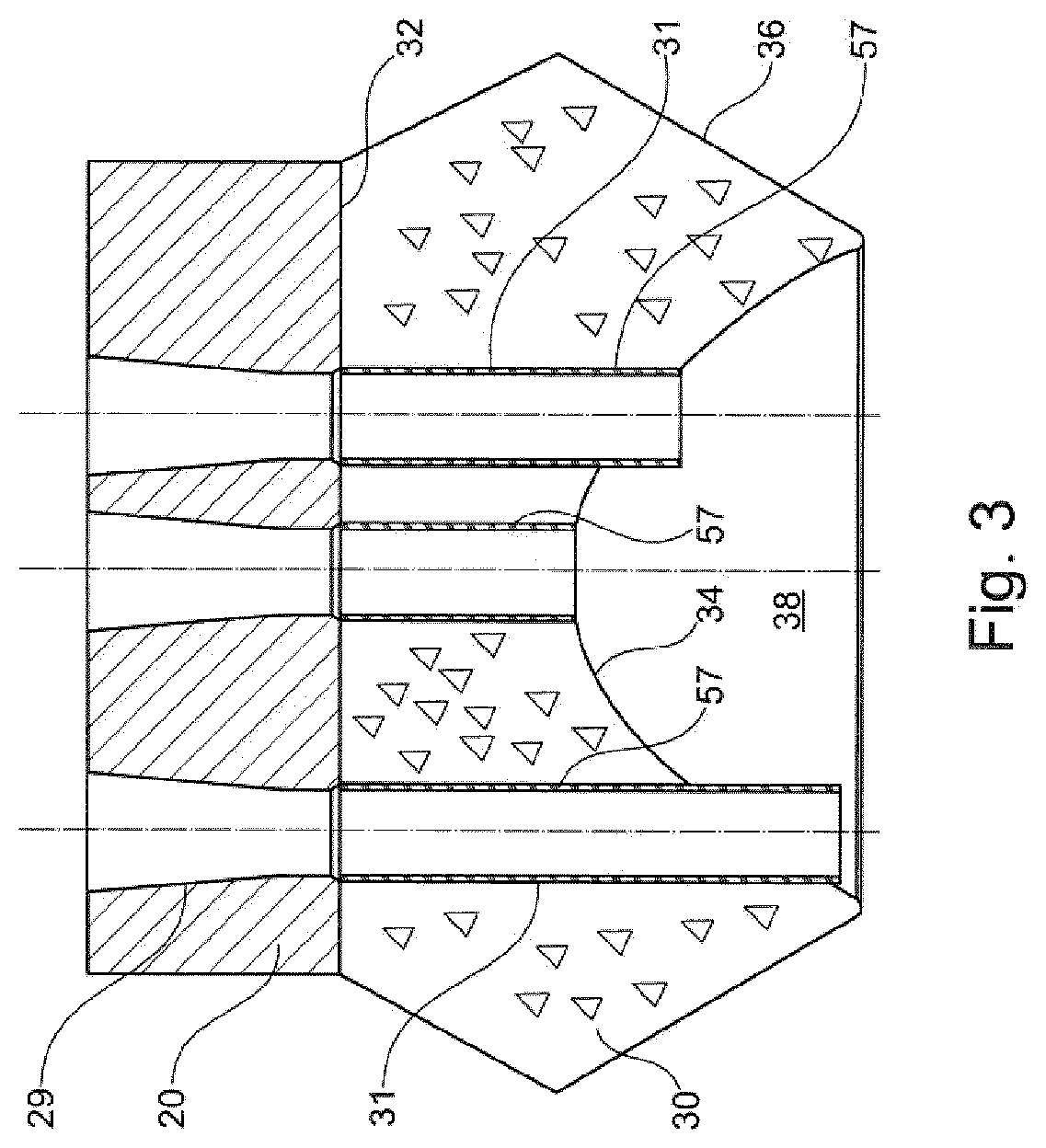
[0056] The anchoring device according to the invention may be put in place instead of an anchoring boss.
[0057] Either the anchor sub-block or the aforementioned distribution element may be molded in contact with the other, so as to obtain bearing surfaces of complementary shapes.
[0058] Where appropriate, the anchor sub-block may be produced in a lost mold, said mold being for example made of a thermoplastic material. The distribution element may also be produced in a lost mold.
[0059] The anchor block, when made at least partially of a cementitious material, may itself also be produced in a lost mold. It may also be counter-molded on the sub-block, or vice versa.
[0060] The invention also relates, independently or in combination with the above, to a system for anchoring prestressing reinforcements or a structural cable, in particular for an anchoring device as defined above, comprising clamping jaws (also referred to as `anchoring jaws`) for clamping the reinforcements and an anchor block made of UHPFC, having housings of conical shape for receiving the jaws and ensuring the reinforcements are wedged under the effect of the tension therein, the anchor block having a face through which the forces are transmitted to the structure, this face being convex toward the structure.
[0061] Such a system may have all or some of the features listed above. In particular, the housings for receiving the jaws may comprise metal inserts, in particular having at least one portion of conical shape. The anchor block may include as many passages for the reinforcements as there are reinforcements. The system may include a bursting reinforcement at the periphery of the anchor block, on the side away from the face that transmits the forces. The anchor block may have an outer surface widening toward the face that transmits the forces to the structure of the structural works, in particular of frustoconical shape.
[0062] The invention also relates, independently or in combination with the above, to an anchor sub-block, in particular for an anchoring device as defined above, made of HPC or UHPFC, comprising a bearing face for receiving an anchor block for anchoring prestressing reinforcements or a structural cable, in particular an anchor block of a system as defined above, passages for said reinforcements, a force-transmitting peripheral portion and a central portion defining, on the side opposite to the bearing face, a concave portion. The peripheral portion may have an end face joined substantially perpendicularly to the concave surface of the central portion, better still forming an acute angle with the tangent to said concave surface at its outer edge. The sub-block may have an outer shape of revolution about the axis along which the tension is applied in the reinforcements. The aforementioned bearing face may be concave in shape, in particular complementary to that of the anchor block. Alternatively, said bearing face is flat. The sub-block may consist exclusively of UHPFC, without integrated reinforcement. The surface of the concave-shaped central portion may be spherical, and better still of non-constant curvature, decreasing in the direction away from the apex, being for example parabolic.
[0063] The sub-block may include a shell of a non-cementitious material constituting a lost mold. The sub-block may comprise, on at least one of its faces intended to be compressed, for example the bearing face for the anchor block or that intended to rest on the distribution element, reliefs intended to be crushed under the force, for example a set of fine ribs of low height.
[0064] The sub-block may include sheaths for the passage of the reinforcements that pass through the cementitious material. These sheaths may protrude into the concave portion of the anchor sub-block, which may facilitate their being cut by allowing a straight cut. These sheaths may be closed off during molding of the anchor sub-block.
[0065] The invention also relates, independently or in combination with the above, to a distribution element, in particular for an anchoring device as defined above, comprising a body made of HPC, traversed by a central opening for the passage of the prestressing reinforcements or structural cable, having a surface for receiving an anchor sub-block and a peripheral outer surface which widens in the direction away from the surface, in particular of frustoconical shape.
[0066] The central opening may have a cross section that increases toward the anchor sub-block. The distribution element may have a face on the opposite side to the anchor sub-block which is flat and perpendicular to the axis of the central opening.
[0067] The distribution element is preferably made with a duct for injecting a cement grout or a grease or wax.
[0068] The distribution element may be produced with a lost mold.
[0069] The invention also relates, independently or in combination with the above, to an anchoring device for concrete structural works, comprising an anchor block for anchoring prestressing reinforcements, an anchor sub-block on which the anchor block rests, and a distribution element to be embedded at least partially in the concrete structure of the structural works, the anchor sub-block and the distribution element being made at least partially of cementitious materials of compressive strength greater than that of the concrete of the structure, the compressive strength of the anchor sub-block being greater than that of the distribution element. Such an arrangement makes it possible to distribute the forces in the structure without exceeding the mechanical strength of each component, it being possible to produce the distribution element with a size greater than that of the sub-block, from a less expensive material. Each component may be given the shape that allows it to work predominantly in compression.
[0070] The anchor sub-block is preferably made of UHPFC. The distribution element may be made of a material with a lower mechanical strength than UHPFC, in particular made of HPC.
[0071] The anchor block may be made of a cementitious material, in particular UHPFC.
[0072] Such a device may comprise a system as defined above, an anchor sub-block as defined above, and/or a distribution element as defined above. At least one divider element which is not made of a cementitious material, in particular in the form of a metal strip or a thickness of plastic, may be inserted between the anchor block and the sub-block, or between the latter and the distribution element.
[0073] The mold or molds for producing the anchor block, the sub-block and/or the distribution element may be produced by 3D printing.
[0074] A better understanding of the invention may be gained on reading the following detailed description of non-limiting embodiments of the invention, and on examining the attached drawing, in which:
[0075] FIG. 1 schematically and partially shows concrete structural works having an anchoring device according to the invention,
[0076] FIG. 2 shows, in axial section, an alternative anchoring device according to the invention,
[0077] FIG. 3 shows an alternative embodiment of a sub-block, with the anchor block shown placed on top,
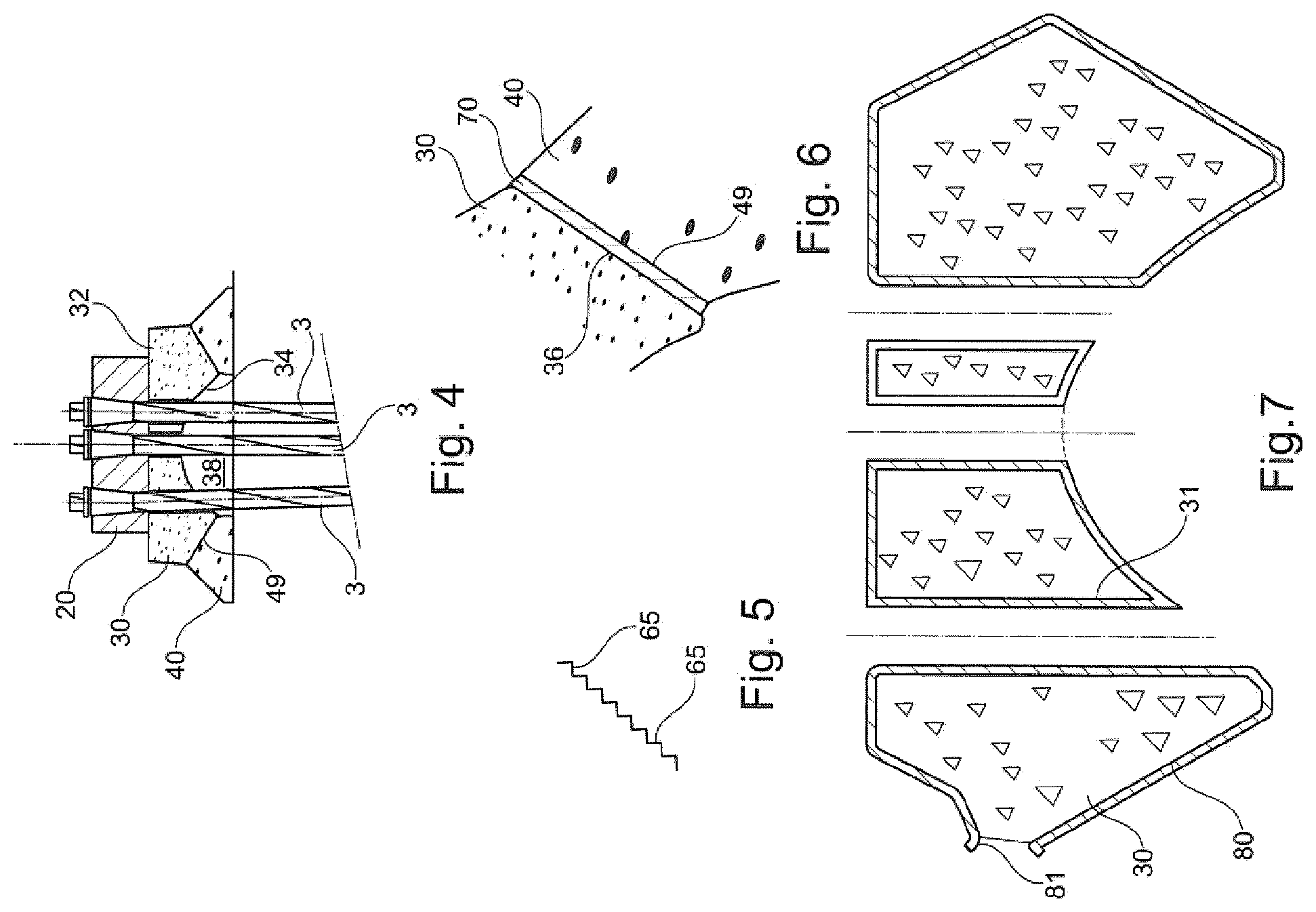
[0078] FIG. 4 is a view similar to FIG. 2, of an alternative embodiment of the anchoring device,
[0079] FIG. 5 shows an example of a relief that may be produced on the face of the anchor sub-block intended to bear on the distribution element,
[0080] FIG. 6 shows the use of a divider element at the interface between the anchor sub-block and the distribution element,
[0081] FIG. 7 is an example of a lost mold which may be used for molding the anchor sub-block and,
[0082] FIG. 8 shows the possibility of replacing the distribution element with a corresponding shape produced directly on the structural works.
[0083] FIG. 1 partially shows structural works comprising a concrete structure 1 within which at least one anchoring device 10 according to the invention is integrated.
[0084] This anchoring device 10 serves to keep under tension (`anchor`) reinforcements 3 constituting cables, for example cables formed from a bundle of substantially parallel strands, of all grades of steel, galvanized, greased and/or sheathed individually. Each strand of the cable may itself be made up of multiple wires. The cable formed by reinforcements 3 connected to the same anchoring device may be made up, for example, of from 1 to 61 strands, better still from 2 or 3 to 61, each strand being, for example, a T15.7 strand. The number of reinforcements may be even higher for a guy, for example up to 200.
[0085] The reinforcements 3 are not limited to cable strands, and may be wires or threaded bars, in which case they are tensioned by tightening a nut engaged on the thread of the bar.
[0086] The reinforcements 3 may or may not be bonded to the structure 1, depending on whether the prestressing is bonded or unbonded.
[0087] The reinforcements 3 pass through the structure 1 by means of a duct 8, which may be covered internally with a sheath 58, for example made of a thermoplastic material or a ribbed (ringed) metal strip. The reinforcements 3 may be embedded within the duct in a grease, in the case of unbonded prestressing, or in a cement grout which sets, in the case of bonded prestressing.
[0088] The structural works 1 preferably have, as shown, a recess 2 for receiving a seal or a cap (not shown) for protecting the anchoring device 10, after fitting and tensioning of the reinforcements 3.
[0089] The concrete of the structure 1 has a conventional compressive strength, typically of the order of 30 to 35 MPa, for example between 20 MPa And 45 MPa.
[0090] The anchoring device 10 comprises, in the example shown, an anchor block 20, a sub-block 30 and a distribution element 40, also known as a `trumplate` by analogy with existing distribution elements.
[0091] The anchor block 20 serves to retain the ends 3a of the reinforcements 3, by virtue of jaws 21 of conical shape, each made up of keys and a retention ring 59, in a conventional manner.
[0092] The jaws 21 are received in metal inserts 22, themselves arranged in housings 29 of complementary shape in the anchor block 20. The inserts 22 have a conical shape where the jaws 21 are received, such that traction on the reinforcement 3 engaged in the jaw 21 is accompanied by radial clamping and indentation of the jaw 21 on the reinforcement, this being stronger the more intense the traction.
[0093] In the example shown, only three reinforcements 3 are visible, but the invention is not limited to a particular number of prestressing reinforcements, or to a particular arrangement of these reinforcements with respect to the axis X of the anchoring device 10.
[0094] In the example of FIG. 1, the anchor block 20 is made of UHPFC, with a bursting reinforcement 23 in the upper part, at its periphery, in the form of a metal hoop.
[0095] The anchor block 20 has a base 25 widening toward an inner face 24, which is convex toward the structure 1. The base 25 has, for example, a frustoconical peripheral outer surface, of revolution or not about the axis X, preferably with axial symmetry. The reinforcements 3 may be arranged in a hexagonal configuration around a central reinforcement (or a central triplet), for example.
[0096] The lower face 24 has, for example, the shape of a spherical cap.
[0097] The sub-block 30 is also made of UHPFC, in the example shown.
[0098] It has a body traversed by as many holes 31 as reinforcements 3. These holes are each lined with a sheath 57 in the example shown.
[0099] The sub-block 30 has a bearing face 32 of concave shape, complementary to the convex face 24 of the anchor block 20, for example in the shape of a spherical cavity of revolution about the axis X.
[0100] The sub-block 30 has a general shape of an arch, and bears on the distribution element 40 via a peripheral portion 33.
[0101] The arched face 34 of the sub-block 30, within the peripheral portion 33, is concave toward the distribution element 40 and defines under the central part of the sub-block 30 a cavity 38, into which the holes 31 for the passage of the reinforcements 3 open.
[0102] The distribution element 40 is hollow and has a central opening 41 which flares toward the sub-block 30 and which is traversed by the cables 3. In the example in question, the opening 41 is frustoconical.
[0103] The arched face 34 is for example, as shown, spherical of revolution about the axis X, but may advantageously be otherwise concave, as will be described below.
[0104] The peripheral portion 33 bears on a surface 49 of the distribution element 40 via an annular bearing surface 36 which converges toward the structure 1 and which is for example frustoconical, as shown. The bearing surface 36 is, for example, oriented substantially perpendicular to the arched face 34, as shown.
[0105] The concave portion 38 may have an opening, given by the half-angle a at the apex of the cone passing through the outer edge of the concave portion 38 and perpendicular to the concave surface 34 at this edge, of between 15 and 90.degree., and preferably between 30 and 90.degree..
[0106] The surface 49 of the distribution element has the same orientation as the surface 36 of the sub-block, being of complementary shape, and being at least as wide as the surface 36.
[0107] The edge 53 of the opening 41 may be located, as shown, substantially at the junction between the arched face 34 and the bearing surface 36.
[0108] The distribution element 40 has a shape that widens, i.e. flares, within the structure 1, with for example an outer surface 46 of frustoconical shape, in the extension of the sub-block 30 toward the inside of the structure 1
[0109] The distribution element 40 may be made of a material with a compressive strength in between that of the concrete of the structure 1 and that of the sub-block 30, preferably high-strength concrete HPC. A plurality of force transmission elements are thus arranged between the anchor block 20 and the concrete of the structure 1, the strength of which is decreasing from the reinforcements 3 to the element 40 in contact with the concrete of the structure, and the size (in particular the largest dimension) of which may be increasing, as shown.
[0110] The distribution element 40 may have an end face 47 perpendicular to the axis X, as shown in FIG. 1, that is to say perpendicular to the direction in which the stress is exerted in the structure 1.
[0111] To use the device of FIG. 1, the distribution element 40 is positioned in the extension of the duct 8, and the concrete of the structure 1 is poured. The opening 41 in the distribution element 40 may be connected to a sheath 52 lining the duct 8 by a transition element (not shown) of generally conical shape, also called a `trumpet`, which may simply be a flared tube. After the concrete of the structure 1 has been poured, set and the formwork removed, the reinforcements 3 are inserted into the duct 8 and through the distribution element 40.
[0112] The sub-block 30 and the anchor block 20 are then put in place with the jaws 21.
[0113] A cylinder, preferably a hydraulic cylinder, is then used for tensioning the reinforcements 3, which are anchored under tension in the anchor block 20 by wedging the jaws 21 on each reinforcement 3.
[0114] The sub-block 30, made of UHPFC, and the distribution element 40, made of HPC, may be cast or extruded on site, i.e. in a workshop located close to the construction site (typically less than 50 km). The same applies, where appropriate, to the anchor block 20 when the latter is made of UHPFC. The various metal inserts may be put in place in a suitable formwork, followed by casting or extrusion of the concrete and placing in an oven.
[0115] In order to obtain a good form fit of the bearing surfaces 36 of the sub-block 30 and 49 of the distribution element 40, they may be molded in contact with one another.
[0116] The dimensions of the anchor block 20, of the sub-block 30 and of the distribution element 40 may be parameterized as a function of the strength and the geometry of the structure 1 for which the anchoring device 10 is intended, for a given prestressing force to be distributed therein.
[0117] In particular, when the size of the distribution element 40 is sufficient, it may not be necessary to integrate, in the structure 1, passive reinforcements, in particular distribution and hooping reinforcements, close to the anchoring device 10, in particular under the latter and around the distribution element 40.
[0118] However, it is possible to integrate into the structure 1, around the duct 8, a helical reinforcement 51, as shown, to take account of the fact that the reinforcements 3 may be stressed radially by the duct 8.
[0119] The shapes given to the anchor block 20, the sub-block 30 and the distribution element 40 make it possible to stress the cementitious material of which they are composed predominantly in compression, under the effect of the tension force prevailing in the prestressing reinforcements 3. In particular, the tensile stresses in the cementitious material of these elements preferably never exceeds 1/20 of the compressive strength of the cementitious material concerned.
[0120] The sub-block 30 transmits, by its internal arched shape, the force received from the anchor block 20 via predominantly compressive internal stresses.
[0121] The distribution element 40 and the structure 1 may be molded with a duct 60 for the passage of a pipe for injecting a grease or a cement grout into the duct 8.
[0122] In the example of FIG. 1, the anchor block 20 is made of UHPFC.
[0123] In the alternative embodiments of FIGS. 2 to 4, the anchor block 20 is made of metal, being for example made of steel, and its face 24 resting on the anchor sub-block 30 is flat and perpendicular to the axis X.
[0124] In this case, the anchor sub-block 30 has a flat bearing surface 32 which is also perpendicular to the axis X.
[0125] FIG. 2 shows the possibility for the concave face 34 to be non-spherical, in this case parabolic. The concave portion 38 is thus deeper, which makes it possible to accentuate the arch function, thereby further preventing the occurrence of tensile stresses in the sub-block 30.
[0126] The angle a' defined as the half-angle at the apex of the cone in which the face 36 is inscribed, is less open than the angle a in the example of FIG. 1.
[0127] The face 36 of the peripheral portion 33 makes an acute angle b with the tangent to the concave surface 34 taken at the outer edge of the concave portion 38. This angle b is, for example, of the order of 30.degree., preferably between 15 and 90.degree. (upper limit excluded), and better still between 20 and 60.degree..
[0128] FIG. 3 shows the possibility for the sheaths 57 to protrude beyond the side of the concave portion 38. It is not in fact necessary to cut the sheaths to the exact profile of the concave portion, given that these sheaths 57 are closed off during the casting of the cementitious material of the sub-block 30.
[0129] The alternative embodiment of FIG. 4 differs from that of FIG. 2 in that the distribution element 40 is shallower, and by the shape of the concave portion 38.
[0130] In this case, the structure 1 may comprise surface and/or bursting reinforcements, under the distribution element 40.
[0131] It is desirable for the sub-block 30 to bear on the distribution element 40 in a relatively homogeneous manner over the entire width of the surface 36.
[0132] However, manufacturing tolerances may lead to defects in terms of evenness or slope, detrimental to a homogeneous transmission of forces.
[0133] In order to prevent disparities in the shape of the surfaces 36 and 49, the sub-block 30 may be counter-molded on the distribution element 40, or vice versa. Likewise, the anchor block 20 may be counter-molded on the sub-block 30, or vice versa.
[0134] In the absence of counter-molding, it is possible to produce on the sub-block 30 and/or the distribution element 40, striations 65 as shown in FIG. 5. These striations 65 have fragile ridges which break under the pressure exerted and which are crushed where the stresses are locally the strongest, levelling out the degree of stress across the entire surface and compensating for manufacturing tolerances. It consists in a sort of hammering of one or both of the facing surfaces.
[0135] It is also possible, as shown in FIG. 6, to insert at least one divider element 70 between the sub-block 30 and the distribution element 40.
[0136] This divider element 70 may be crushed under the pressure of bearing of the sub-block 30 on the distribution element 40 and thus absorb, by local deformation, the highest stresses by the redistribution effect.
[0137] The divider element 70 may be a strip of a ductile metal, for example lead, or a sheet of a polymeric material.
[0138] The divider element 70 may also promote the sliding of the sub-block 30 relative to the distribution element 40 when an acute angle of wedging b exists.
[0139] FIG. 7 shows the possibility of producing the sub-block 30 using a lost mold 80. The latter may have an opening 81 on the side for filling. In this case, the wall of the mold 80 constitutes an element which is inserted between the surface made of cementitious material of the sub-block and that of the distribution element 40 and which may play the role of the aforementioned divider element.
[0140] The distribution element 40 may also be produced using a lost mold, as may the anchor block 20.
[0141] Naturally, the invention is not limited to the examples that have just been described.
[0142] For example, the shape of the anchor block, the anchor sub-block and the distribution element may be modified to give them another shape, while still allowing the cementitious material of which they are composed to be stressed predominantly in compression.
[0143] The anchor sub-block may have a shape without symmetry of revolution, with or without axial symmetry, with, for example, multiple, substantially radial or non-radial arches starting from the central body.
[0144] The arched face 34 of the sub-block 30 may or may not have one or more ridges, with one or more facets, in the form of an ogive, a cone, a quadric, a pointed arch. Preferably, however, the presence of ridges will be avoided.
[0145] Also preferably, the shape of the arched face is such that it has an inclination (slope) with respect to the plane normal (orthogonal) to the axis X at its apex, which increases away from this plane, preferably continuously. The variation in the slope is thus monotonous. The curve (not being inverted) may or may not be regular.
[0146] The anchor sub-block 30 may be made with a peripheral portion 33 which is not solid and continuous in an annular shape but has apertures, which extend for example as far as the distribution element 40 so as to form separate legs for bearing on the latter.
[0147] The surface 36 of the sub-block 30 may be indented, and the distribution element 40 is thus advantageously indented in a complementary manner. Such a form fit may be relatively easy to create when the sub-block 30 is molded in contact with the distribution element or vice versa.
[0148] The bearing face 32 of the sub-block intended to receive the anchor block 20 may be non-spherical, for example in the form of a cone, an ogive, a quadric, in particular a paraboloid.
[0149] The outer peripheral surface of the anchor block or sub-block may be of revolution or not, preferably with axial symmetry. For example, the shape of the block, of the sub-block or of the distribution element is generated by n repetitions of the same pattern by rotating by an angle of 360.degree./n, n being equal to 3, for example, in particular in the case of a hexagonal mesh for the bundle of reinforcements 3.
[0150] FIG. 8 shows the possibility of replacing the distribution element 40 by a corresponding complementary shape made directly within the structural works 1. This is possible when the cementitious material of the structural works has sufficient mechanical strength, for example a concrete of strength class C80/95 or greater.
[0151] The complementary shape has, as shown, a cone for receiving the anchor sub-block 30, against which the face 36 of the anchor sub-block bears.
[0152] Although the invention is particularly suitable for concrete structural works, the invention may also be applied to a masonry or mixed, for example steel/concrete, structure.
[0153] Although a cementitious material is preferred for producing the anchor sub-block, it is also possible, as an alternative, to use materials less expensive than steel, such as cast iron, or a polymer-based composite material.
* * * * *
D00000
D00001
D00002
D00003
D00004
D00005
XML
uspto.report is an independent third-party trademark research tool that is not affiliated, endorsed, or sponsored by the United States Patent and Trademark Office (USPTO) or any other governmental organization. The information provided by uspto.report is based on publicly available data at the time of writing and is intended for informational purposes only.
While we strive to provide accurate and up-to-date information, we do not guarantee the accuracy, completeness, reliability, or suitability of the information displayed on this site. The use of this site is at your own risk. Any reliance you place on such information is therefore strictly at your own risk.
All official trademark data, including owner information, should be verified by visiting the official USPTO website at www.uspto.gov. This site is not intended to replace professional legal advice and should not be used as a substitute for consulting with a legal professional who is knowledgeable about trademark law.