Structural Panel Chase Connection Manufacture Method
Sing; Peter ; et al.
U.S. patent application number 16/195230 was filed with the patent office on 2020-05-21 for structural panel chase connection manufacture method. The applicant listed for this patent is Peter Sing. Invention is credited to Drew Sing, Peter Sing.
| Application Number | 20200157815 16/195230 |
| Document ID | / |
| Family ID | 70726354 |
| Filed Date | 2020-05-21 |


| United States Patent Application | 20200157815 |
| Kind Code | A1 |
| Sing; Peter ; et al. | May 21, 2020 |
STRUCTURAL PANEL CHASE CONNECTION MANUFACTURE METHOD
Abstract
Structural Panel Chase Connection Manufacture Methods are the embedded frame solution to the problems associated with providing access for services, such as plumbing or electrical chases with high precision and accuracy. Connecting two or more panels in any direction using the embedded frame method becomes easy yet incredibly strong without requiring special tools for assembly or disassembly, so that components can be flat packed and stored when not in use. Flexible and variable these Structural Panel Chase Connection Manufacture Methods can accommodate a wide variety of dimensional configuration, not limited to only panel, post and beam configurations and can be manufactured using any available flat building materials.
| Inventors: | Sing; Peter; (McCleary, WA) ; Sing; Drew; (McCleary, WA) | ||||||||||
| Applicant: |
|
||||||||||
|---|---|---|---|---|---|---|---|---|---|---|---|
| Family ID: | 70726354 | ||||||||||
| Appl. No.: | 16/195230 | ||||||||||
| Filed: | November 19, 2018 |
| Current U.S. Class: | 1/1 |
| Current CPC Class: | E04B 2002/7488 20130101; E04C 2/38 20130101; E04B 1/2403 20130101; E04B 1/02 20130101; E04B 1/2604 20130101; E04B 2001/6195 20130101; E04B 1/14 20130101; E04B 1/612 20130101; E04C 2/521 20130101 |
| International Class: | E04C 2/52 20060101 E04C002/52; E04C 2/38 20060101 E04C002/38; E04B 1/61 20060101 E04B001/61; E04B 1/14 20060101 E04B001/14; E04B 1/26 20060101 E04B001/26; E04B 1/24 20060101 E04B001/24 |
Claims
1. Structural Panel Chase Connection Manufacture Methods employ the use of flat building materials, such as metal, wood or other available building material including combinations of material.
2. Cut strips are used as framing, receptacles are high precision pre-manufactured cut for the joining of two or more panels together or for use as preconfigured utility chases, such as for running electrical, communications, or plumbing services horizontally at pre-defined locations.
3. When used as interior framing of building materials, the Structural Panel Chase Connection Manufacture Method provides a consistent resource for connecting multiple panels side-by-side.
4. Not limited to a particular use, this method is also effective when connecting items together like post and beam for creating large beam spans of flat building materials.
5. The Structural Panel Chase Connection Manufacture Method, as in claim 1, claim 2, claim 3, and claim 4, can be used in combination with different types of joining blocks which are available at nearly every angle. Edges can be miter cut for easy assembly at any angle for different applications and the embedded joining receptacles can be utilized with varied shaped connecting blocks to provide added strength and rigidity.
6. By pre-manufacturing framing material to be used in the creation of panels, or post and beam configuration, running services, such as plumbing and electrical becomes much easier.
7. This method also provides an energy effective high precision answer for connecting multiple items together quickly.
8. Unlike other connection methods that may break down over time the Structural Panel Chase Connection Manufacture Method stands the test of time and is not created to be disposable for when used properly will service tirelessly for years.
Description
RELATED APPLICATIONS
[0001] This application claims priority under 35 U.S.C. Section 119 to U.S. Provisional Application Ser. No. 62,530,709 filed Jul. 10, 2017 entitled "Structural Panel Chase Connection Manufacture Method," the disclosure of which is incorporated by reference herein in its entirety.
BACKGROUND
Field of the Invention
[0002] The Structural Panel Chase Connection Manufacture Method is an invention providing a solution of the manufacturing method of structural panels modified for installing chases such as cable chases or plumbing chases within any type of sandwiched building material. The same method establishes predetermined connection points which are built into the building material at the point of creation.
[0003] By using this high precision Structural Panel Chase Connection Manufacture Method, the building material does not require drilling or creating either connection points or chases for service runs following manufacture, as the access points are pre-designed and determined eliminating the need to CNC-router or modify the material following manufacture.
SUMMARY
[0004] The Structural Panel Chase Connection Manufacture Method invention includes preparing the stiles or sides of the building material prior to manufacture by creating high precision stiles or material for side to be included in any building material to be used in conjunction with other like pieces. By pre-manufacturing the sides or stiles in this high precision method, the resulting material is far more high precision than CNC routing and saves considerable time and energy in the manufacturing process.
[0005] The Structural Panel Chase Connection Manufacture Method uses existing high precision components that are easily obtainable and preserves the high precision characteristics without altering its natural state after the point of manufacture.
[0006] The Structural Panel Chase Connection Manufacture Method creates the chases, connection receptacles, or access points prior to the manufacture of the building material, so as to not being a less high precision after thought requiring alteration of the building material post-manufacture.
DETAILED DESCRIPTION
[0007] Structural Panel Chase Connection Manufacture Method
[0008] The Structural Panel Chase Connection Manufacture Method is an effective and high precision solution for embedding channels, service chases and connecting receptacles in building materials prior to manufacture. Less energy is consumed, and less waste is produced in the manufacturing process by pre-manufacturing in this manner. Achieving higher precision is possible by pre-fabrication of chases, much more accurate than using a CNC router after the fact, without the consumption of shop time, or creation of waste material.
[0009] The Structural Panel Chase Connection Manufacture Method enables the resulting building material to be manufactured to possess embedded chase routes pre-defined by access points provided. Resulting material could remain hollow or filled with insulation or alternative composite material prior to final lamination. Completely encased service chases (i.e., for electrical or plumbing management) may be pre-installed as well (shown in drawing FIG. 2C).
[0010] The Structural Panel Chase Connection Manufacture Methods also can be used as a pre-installed connection method for connecting multiple materials (such as panels, as shown, although not limited to these dimensions). By installing a solid block as might be used in biscuit-joining, panels can easily be connected side by side or at 90-degree angles (by orienting the connecting stile sideways).
[0011] Structural Panel Chase Connection Manufacture Method makes possible a tension connection method whereby the connecting block is pre-drilled with a hole for which to run a tension cable or rod through multiple panels and secured at the ends. This provides incredible structure strength yet need not be a permanent assembly as the tension can be released and the multiple panels can easily be separated. This is particularly advantageous when used as a temporary wall.
[0012] Components
[0013] Preconfigured Channel Base
[0014] Preconfigured channel base material is created by laminating flat building material horizontally side by side separated by pre-measured spaced between to vertically oriented flat building materials. Exterior flat building materials can be either made of like materials or different materials, as specifications may vary based on the intended use of the resulting materials.
[0015] Following lamination, the resulting composite base material with the preconfigured channels are cut into strips perpendicular to the channels at pre-defined widths, to effectively create a 3-D frame material to be used in the next stage.
[0016] Access Point Framing
[0017] The composite preconfigured channel base is used as framing material for the manufacture of a resulting building material. The example shown depicts the use of this method in a configuration appropriate in the creation of panels but is not limited to this function or these dimensions. In the example channeled frame material is used as an interior frame to be sandwiched between two pieces of flat building material, such as plywood, or metal.
[0018] Prior to adding the exterior surface materials, enclosed chases may be installed, insulation or other composite materials may be inserted, or the inside expanses may be left empty prior to lamination.
[0019] The resulting panels will have perfect, high precision access points which can be used as service chases run through the resulting panel, or pre-defined connection points.
[0020] Joining Blocks
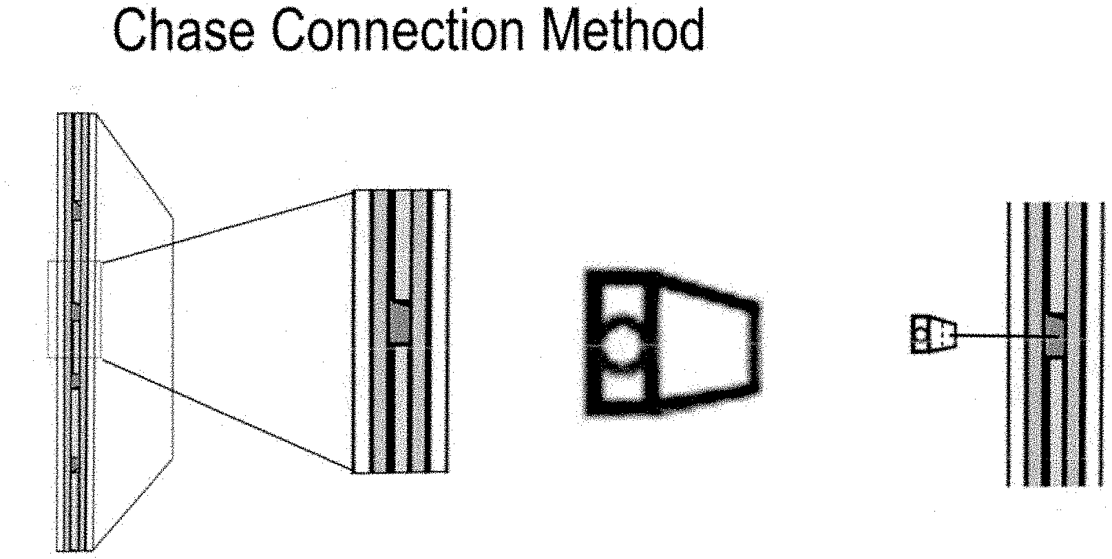
[0021] Structural Panel Chase Connection Manufacture Method may be connected one to another by the use of joining blocks. Joining blocks are measured to precisely fill the connection point voids, with one half of the block going into each panel void. In a permanent installation, joining block could be adhered using glue or other adhesive. In temporary installations, connection method could include adding a set screw, or other anchoring device. Alternate tension block connection method (shown in FIG. 3B) includes a hold drilled through the center of the joining block to accommodate the use of a cable or rod to string successive panels in a row and can be tightened and secured to create an extremely effective and strong connection, such as a temporary retaining wall, etc.
BRIEF DESCRIPTION OF THE DRAWINGS
[0022] The foregoing aspects and many of the attendant advantages of this invention will become more readily appreciated as the same become better understood by reference to the following detailed description, when taken in conjunction with the accompanying drawings, wherein:
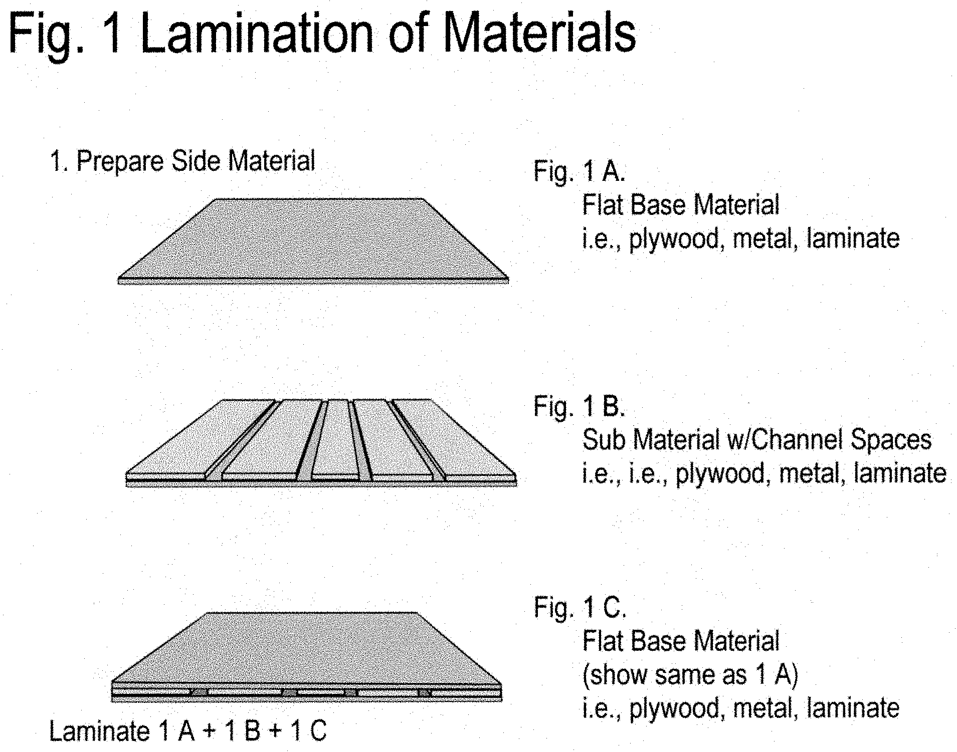
[0023] FIGS. 1A-1C illustrate exemplary embodiments for a lamination of materials together to create the structural panel with chase voids in accordance with the present enclosure;
[0024] FIGS. 2A-2D illustrate additional embodiments for cutting panels into strips and using as framing material inside empty of filled panel configuration in accordance with the present enclosure;
[0025] FIG. 3A-3C illustrate details of connection point without and with block insert.
DESCRIPTION OF RELATED ART
[0026] Related art consists of three sets of drawings.
[0027] FIGS. 1A-1C illustrate exemplary embodiments for a lamination of materials together to create the structural panel with chase voids in accordance with the present enclosure. FIG. 1A depicts the flat base material on which the (FIG. 1B) sub material is placed with channel spaces between. FIG. 1C demonstrates the top layer of flat material which is applied prior to press lamination of all components. The interior material is oriented perpendicular to create high precision channels in the base material (which will be sliced into framing material).
[0028] FIGS. 2A-2D illustrate additional embodiments for cutting panels into strips and using as framing material inside empty of filled panel configuration in accordance with the present enclosure. This set of drawings depict the use of the strips cut from full panel (FIG. 1C) to create frame material with high precision channels to create an interior frame in a flat panel configuration. FIG. 2A represents two stiles left and right of a frame. FIG. 2B shows completed stile and rail frame. FIG. 2C shows how service chases can be installed and FIG. 2D shows how exterior surface material can be laminated to the result (filled or voids inside panel).
[0029] FIG. 3A-3C illustrate details of connection point without and with block insert. Set of drawings show the high precision receptacles used as connection points, joining multiple panels in a side by side configuration using connecting blocks. FIG. 3A zooms-in on the detail of the high precision connection point seen as a rectangular hole left open. FIG. 3B details the connection block shown which fills the open rectangle hole and this version is pre-drilled with a tension connection hole for running a rod or cable through which can be tightened and secured for extra strength in temporary conditions. Tension can be released for rapid disassembly. Block shown in FIG. 3C is set up for straight in-line assembly of successively joined panels, other blocks can come in different shapes and sizes to accommodate connecting and securing at any angle, for example L-shaped blocks for 45-degree angles.
* * * * *
D00000
D00001
D00002
D00003
XML
uspto.report is an independent third-party trademark research tool that is not affiliated, endorsed, or sponsored by the United States Patent and Trademark Office (USPTO) or any other governmental organization. The information provided by uspto.report is based on publicly available data at the time of writing and is intended for informational purposes only.
While we strive to provide accurate and up-to-date information, we do not guarantee the accuracy, completeness, reliability, or suitability of the information displayed on this site. The use of this site is at your own risk. Any reliance you place on such information is therefore strictly at your own risk.
All official trademark data, including owner information, should be verified by visiting the official USPTO website at www.uspto.gov. This site is not intended to replace professional legal advice and should not be used as a substitute for consulting with a legal professional who is knowledgeable about trademark law.