Electric Load-Haul-Dump Mining Machine
Huff; Brian R. ; et al.
U.S. patent application number 16/434390 was filed with the patent office on 2020-05-21 for electric load-haul-dump mining machine. The applicant listed for this patent is Artisan Vehicle Systems, Inc.. Invention is credited to Kyle Hickey, Brian R. Huff.
| Application Number | 20200157769 16/434390 |
| Document ID | / |
| Family ID | 69722775 |
| Filed Date | 2020-05-21 |
View All Diagrams
| United States Patent Application | 20200157769 |
| Kind Code | A1 |
| Huff; Brian R. ; et al. | May 21, 2020 |
Electric Load-Haul-Dump Mining Machine
Abstract
An electric vehicle may include a frame, a set of wheels, and a bucket. In addition, the vehicle may include an electric propulsion system comprising one or more electric motors and one or more electric power sources configured to deliver power to the one or more electric motors. Further, the vehicle may have a payload capacity, the payload capacity being a weight of material that can be loaded into the bucket and transported by the electric vehicle; and the payload capacity may be at least approximately 10 metric tons.
| Inventors: | Huff; Brian R.; (Newbury Park, CA) ; Hickey; Kyle; (Moorpark, CA) | ||||||||||
| Applicant: |
|
||||||||||
|---|---|---|---|---|---|---|---|---|---|---|---|
| Family ID: | 69722775 | ||||||||||
| Appl. No.: | 16/434390 | ||||||||||
| Filed: | June 7, 2019 |
Related U.S. Patent Documents
| Application Number | Filing Date | Patent Number | ||
|---|---|---|---|---|
| 62727930 | Sep 6, 2018 | |||
| Current U.S. Class: | 1/1 |
| Current CPC Class: | E02F 9/20 20130101; E02F 9/02 20130101; E02F 9/18 20130101; E02F 9/207 20130101; E02F 3/342 20130101 |
| International Class: | E02F 9/20 20060101 E02F009/20; E02F 9/18 20060101 E02F009/18 |
Claims
1. An electric vehicle, comprising: a frame, a set of wheels, and a bucket; and an electric propulsion system comprising one or more electric motors and one or more electric power sources configured to deliver power to the one or more electric motors; the electric vehicle having a payload capacity, the payload capacity being a weight of material that can be loaded into the bucket and transported by the electric vehicle; and wherein the payload capacity is at least approximately 10 metric tons.
2. The electric vehicle according to claim 1, wherein the vehicle has a front end and a rear end; wherein the bucket is connected to the frame at the front end of the vehicle; wherein the set of wheels includes a pair of front tires proximate the front end of the vehicle, and a pair of rear tires proximate the rear end of the vehicle; and wherein the front tires are larger than the rear tires.
3. The electric vehicle according to claim 2, wherein the front tires are configured to support a payload of approximately 10 metric tons; and wherein the rear tires are configured to support a maximum payload of no more than approximately 7 metric tons.
4. The electric vehicle according to claim 2, wherein the one or more electric power sources include a first power source configured to deliver power to the front tires and a second power source configured to deliver power to the rear tires.
5. The electric vehicle according to claim 2, wherein the frame proximate the rear tires is configured to provide rear visibility that corresponds with a vehicle having a maximum payload capacity that is substantially less than 10 metric tons.
6. The electric vehicle according to claim 5, wherein the one or more power sources include a battery pack having an angled side edge providing a path of visibility on a driver's side rear of the vehicle.
7. The electric vehicle according to claim 1, wherein the vehicle has a front end and a rear end; wherein the bucket is connected to the frame at the front end of the vehicle; and wherein the frame has a maximum height proximate the front end; wherein the maximum height of the frame proximate the front end of the vehicle corresponds with a vehicle having a maximum payload capacity that is substantially smaller than the payload capacity of the electric vehicle.
8. The electric vehicle according to claim 7, wherein the bucket has a payload capacity of approximately 10 metric tons and the maximum height of the frame proximate the front end of the vehicle corresponds with a vehicle having a maximum payload capacity of no more than approximately 7 metric tons.
9. The electric vehicle according to claim 8, wherein the bucket has a maximum vertical reach that corresponds with a vehicle having a payload capacity of approximately 10 metric tons.
10. The electric vehicle according to claim 7, wherein the bucket is attached to the frame via a linkage that includes a trunnion mounted hydraulic lift cylinder.
11. An electric vehicle, comprising: a frame defining a front end and a rear end of the vehicle; a pair of front tires proximate the front end of the vehicle, and a pair of rear tires proximate the rear end of the vehicle; a bucket connected to the frame at the front end of the vehicle and configured to receive a payload; and an electric propulsion system including: a first electric motor configured to deliver power to the front tires; a first electric power source configured to deliver power to the first electric motor; a second electric motor configured to deliver power to the rear tires; and a second electric power source configured to deliver power to the second electric motor; wherein the front tires are larger than the rear tires; wherein the electric vehicle has a payload capacity, the payload capacity being a weight of material that can be loaded into the bucket and transported by the electric vehicle; wherein the frame proximate the rear tires has a maximum height that corresponds with a vehicle having a maximum payload capacity that is substantially less than the payload capacity of the electric vehicle; wherein the bucket has a maximum vertical reach that corresponds with a vehicle having the same payload capacity as the electric vehicle does; and wherein the frame has a maximum height proximate the front end of the vehicle, the maximum height proximate the front end of the vehicle corresponding with a vehicle having a maximum payload capacity that is substantially smaller than the payload capacity of the electric vehicle.
12. The electric vehicle according to claim 11, wherein the payload capacity of the electric vehicle is at least approximately 10 metric tons.
13. The electric vehicle according to claim 12, wherein the front tires are configured to support a payload of approximately 10 metric tons; and wherein the rear tires are configured to support a maximum payload of no more than approximately 7 metric tons.
14. The electric vehicle according to claim 12, wherein the bucket has a payload of approximately 10 metric tons and the maximum height of the frame proximate the front end of the vehicle corresponds with a vehicle having a maximum payload of no more than approximately 7 metric tons.
15. The electric vehicle according to claim 11, wherein the one or more power sources include a battery pack having an angled side edge providing a path of visibility on a driver's side rear of the vehicle.
16. The electric vehicle according to claim 11, wherein the bucket is attached to the frame via a linkage that includes a trunnion mounted hydraulic lift cylinder.
17. An electric vehicle, comprising: a frame defining a front end and a rear end of the vehicle; a pair of front tires proximate the front end of the vehicle, and a pair of rear tires proximate the rear end of the vehicle; a bucket configured to receive a payload; and an electric propulsion system including: a first electric motor configured to deliver power to the front tires; a first electric power source configured to deliver power to the first electric motor; a second electric motor configured to deliver power to the rear tires; and a second electric power source configured to deliver power to the second electric motor; wherein the vehicle has a front end and a rear end; wherein the bucket is connected to the frame at the front end of the vehicle; and wherein the front tires are larger than the rear tires such that the front tires are configured to support a payload of approximately 10 metric tons and the rear tires are configured to support a maximum payload of no more than approximately 7 metric tons.
18. The electric vehicle according to claim 17, wherein the frame proximate the rear tires is configured to provide rear visibility that corresponds with a vehicle having a maximum payload substantially less than 10 metric tons.
19. The electric vehicle according to claim 18, wherein the frame proximate the rear tires is configured to provide rear visibility that corresponds with a vehicle having a maximum payload of no more than approximately 7 metric tons.
20. The electric vehicle according to claim 18, wherein the at least one of the first power source and the second power source includes a battery pack having an angled side edge providing a path of visibility on a driver's side rear of the vehicle.
Description
CROSS-REFERENCE TO RELATED APPLICATION(S)
[0001] This application claims priority to provisional patent application No. 62/727,930, filed Sep. 6, 2018, and entitled "Zero Emission Electric Mining Vehicle," the entire disclosure of which is incorporated herein by reference. In addition, this application is related to commonly owned U.S. patent application Ser. No. ______, entitled "Battery Load Mechanism for Electric LHD Mining Machine" (Attorney Docket No. 123-1087); U.S. patent application Ser. No. ______, entitled "Electric Power Distribution System and Method for Electric Mining Machine" (Attorney Docket No. 123-1088); and U.S. patent application Ser. No. ______, entitled "Separable Tow Hook Brake Release System" (Attorney Docket No. 123-1089), all filed concurrently herewith on Jun. 7, 2019, and each of which is incorporated herein by reference in its entirety.
BACKGROUND OF THE INVENTION
1. Field of the Invention
[0002] The present disclosure relates broadly to electric machines and vehicles, and more specifically to electric machines and vehicles used in subsurface mines.
2. Description of Related Art
[0003] An overview of a sub-surface mine environment and general description of electric vehicles for mining is described in U.S. Pat. No. 9,994,117, issued on Jun. 12, 2018, titled "System And Method For Providing Power To A Mining Operation," the entire contents of which are hereby incorporated by reference. The present disclosure relates to heavy duty electric powered machines or vehicles that may operate in a continuous work environment such as a sub-surface mine. The battery packs employed in electric mining machines are heavy-duty, high powered battery packs which are comprised of multiple battery modules contained in a pack housing. Each module is comprised of multiple cells. The modules are equipped with an array of operational sensors and are provided with electronic components to provide data from the sensors to a separate maintenance network. Sensors can include temperature sensors, timing devices, charge level detection devices, and other monitoring devices which can be employed to provide an operations center with accurate, real-time data regarding the performance of the module and its performance history. Details of exemplary battery packs and battery management systems and the associated data generation and monitoring can be found in commonly owned U.S. Pat. No. 9,960,396 issued on May 1, 2018, titled "Module Backbone System;" and U.S. Pat. No. 10,063,069 issued on Aug. 28, 2018, titled "Module Maintenance System;" the entire contents of which are hereby incorporated by reference.
[0004] Co-pending and commonly owned U.S. application Ser. No. 15/980,314 filed May 15, 2018, titled "Electrically Powered Mining Vehicle;" U.S. application Ser. No. 15/908,794 filed Feb. 28, 2018, titled "Electric Haul Truck;" U.S. application Ser. No. 15/908,799 filed Feb. 28, 2018, titled "Mounting and Dismounting System for a Battery Assembly;" U.S. application Ser. No. 15/908,802 filed Feb. 28, 2018, titled "Method and System for Mounting and Dismounting Batteries in a Vehicle;" and U.S. application Ser. No. 15/908,804 filed Feb. 28, 2018, titled "Alignment and Locking Mechanism for Removable Battery Assembly" contain descriptions electric mining machines, the batteries, and the sub-surface mining environment, the entire contents of which are hereby incorporated by reference.
[0005] Various types of mining vehicles may be used to remove and transport material in a mining operation. One type of vehicle, a load-haul-dump machine (LHD) may be used. LHDs may be similar to front-end loaders but with features that facilitate better operation in hard-rock mining applications. Typically, LHDs are rugged and highly maneuverable.
[0006] Traditionally, LHDs have been designed to have relatively longer lengths to improve axial weight and bucket capacity. However, the longer length, as well as overall frame geometry of conventional vehicles may limit visibility. Traditional LHDs may also operate with diesel-powered engines that may provide indirect constraints on power and capacity for a machine of a given size and weight.
SUMMARY OF THE INVENTION
[0007] The disclosed vehicle includes features that provide a higher payload capacity while maintaining the benefits of a smaller chassis, such as greater visibility. For example, the disclosed vehicle may include a larger bucket and front tires, but smaller frame and rear tires. A trunnion mounted hydraulic lift cylinder may facilitate the small height of the forward portion of the vehicle frame. Dual propulsion motors may enable differently sized tires to be used in the front and back of the vehicle. In particular, larger tires may be used in the front of the vehicle, in order to support high loads within the bucket, and smaller tires may be used in the rear of the vehicle. The smaller rear tires enable the frame in the rear of the vehicle to have a smaller height. Because of the smaller frame height in the front and rear of the vehicle, the operator may have greater visibility. Other structural features, such as angled surfaces in the rear of the frame and on the side of the battery packs, may provide increased visibility as well.
[0008] In one aspect, the present disclosure is directed to an electric vehicle, comprising: a frame, a set of wheels, and a bucket. In addition, the vehicle may include an electric propulsion system comprising one or more electric motors and one or more electric power sources configured to deliver power to the one or more electric motors. Further, the vehicle may have a payload capacity, the payload capacity being a weight of material that can be loaded into the bucket and transported by the electric vehicle; and the payload capacity may be at least approximately 10 metric tons.
[0009] In another aspect, the present disclosure is directed to an electric vehicle, including a frame defining a front end and a rear end of the vehicle. In addition, the vehicle may include a pair of front tires proximate the front end of the vehicle, and a pair of rear tires proximate the rear end of the vehicle; a bucket connected to the frame at the front end of the vehicle and configured to receive a payload; and an electric propulsion system. The electric propulsion system may include a first electric motor configured to deliver power to the front tires; a first electric power source configured to deliver power to the first electric motor; a second electric motor configured to deliver power to the rear tires; and a second electric power source configured to deliver power to the second electric motor, wherein the front tires are larger than the rear tires. In addition, the electric vehicle has a payload capacity, the payload capacity being a weight of material that can be loaded into the bucket and transported by the electric vehicle. Further, the frame proximate the rear tires corresponds with a vehicle having a maximum payload capacity that is substantially less than the payload capacity of the electric vehicle. Also, the bucket has a maximum vertical reach that corresponds with a vehicle having the same payload capacity as the electric vehicle does. Further, the frame has a maximum height proximate the front end of the vehicle, the maximum height proximate the front end of the vehicle corresponding with a vehicle having a payload capacity that is substantially smaller than the payload capacity of the electric vehicle.
[0010] In another aspect, the present disclosure is directed to an electric vehicle, including a frame defining a front end and a rear end of the vehicle; a pair of front tires proximate the front end of the vehicle, and a pair of rear tires proximate the rear end of the vehicle; a bucket configured to receive a payload; and an electric propulsion system. The electric propulsion system may include a first electric motor configured to deliver power to the front tires; a first electric power source configured to deliver power to the first electric motor; a second electric motor configured to deliver power to the rear tires; and a second electric power source configured to deliver power to the second electric motor; wherein the vehicle has a front end and a rear end; wherein the bucket is connected to the frame at the front end of the vehicle; and wherein the front tires are larger than the rear tires such that the front tires are configured to support a payload of approximately 10 metric tons and the rear tires are configured to support a maximum payload of no more than approximately 7 metric tons.
[0011] Other systems, methods, features and advantages of the invention will be, or will become, apparent to one of ordinary skill in the art upon examination of the following figures and detailed description. It is intended that all such additional systems, methods, features and advantages be included within this description and this summary, be within the scope of the invention, and be protected by the following claims.
BRIEF DESCRIPTION OF THE DRAWINGS
[0012] The invention can be better understood with reference to the following drawings and description. The components in the figures are not necessarily to scale, emphasis instead being placed upon illustrating the principles of the invention. Moreover, in the figures, like reference numerals designate corresponding parts throughout the different views.
[0013] FIG. 1 is a schematic illustration showing a front perspective view of an embodiment of a mining vehicle;
[0014] FIG. 2 is a schematic illustration showing a rear perspective view of the mining vehicle of FIG. 1;
[0015] FIG. 3 is a schematic illustration of a dual motor electric power train system according to an exemplary embodiment.
[0016] FIG. 4 is a schematic illustration showing a right side view of the mining vehicle of FIG. 1;
[0017] FIG. 5 is a schematic illustration showing a right side view of the mining vehicle of FIG. 1 with the payload bucket in various positions;
[0018] FIG. 6 is a schematic illustration of a top side view of the mining vehicle of FIG. 1;
[0019] FIG. 7 is a schematic illustration of a top side view of the mining vehicle of FIG. 1 in an articulating condition and showing the turning radius;
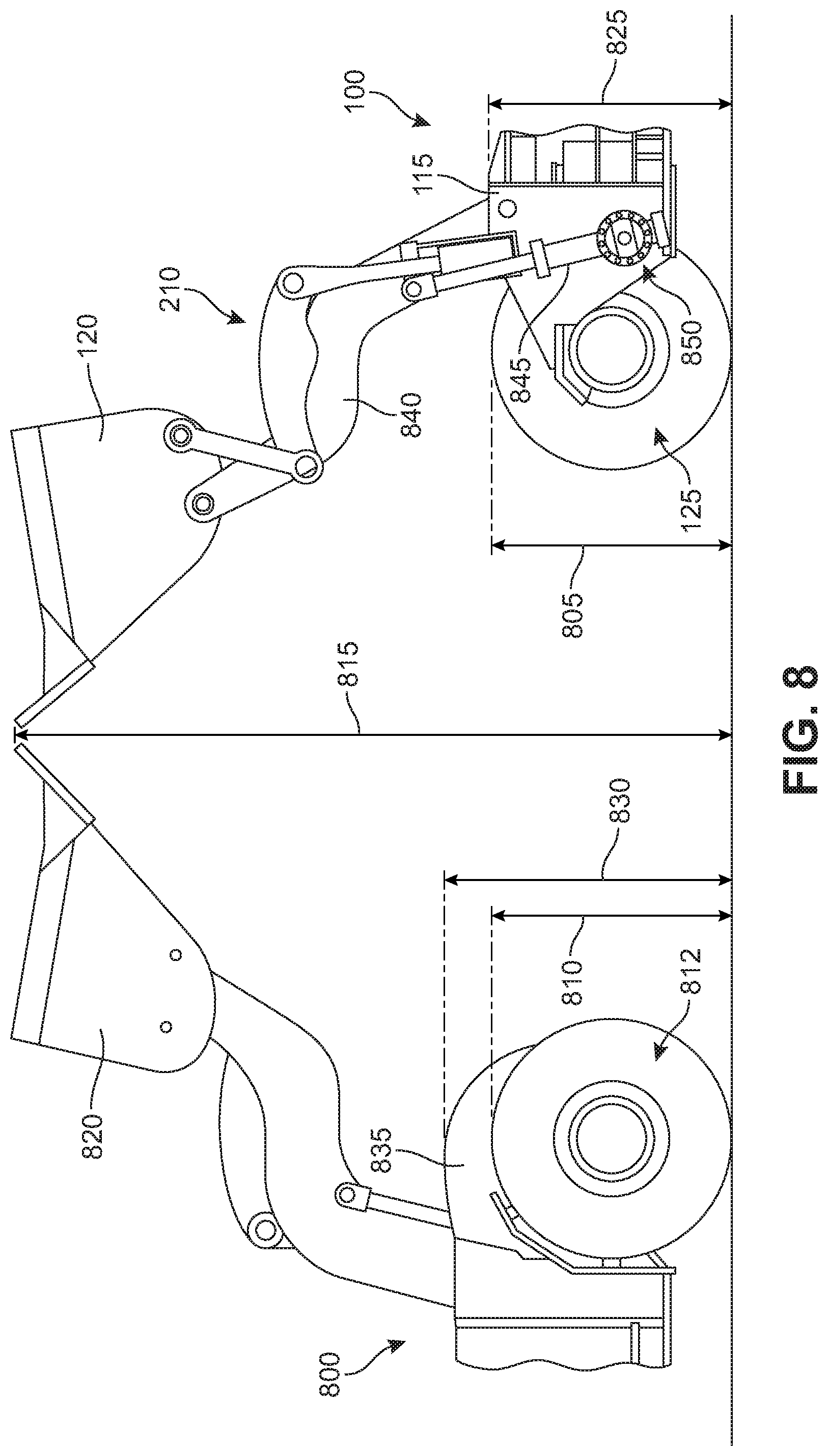
[0020] FIG. 8 shows the vertical bucket reach and chassis height of the vehicle shown in FIG. 1 in comparison with a traditional vehicle configured to haul the same payload;
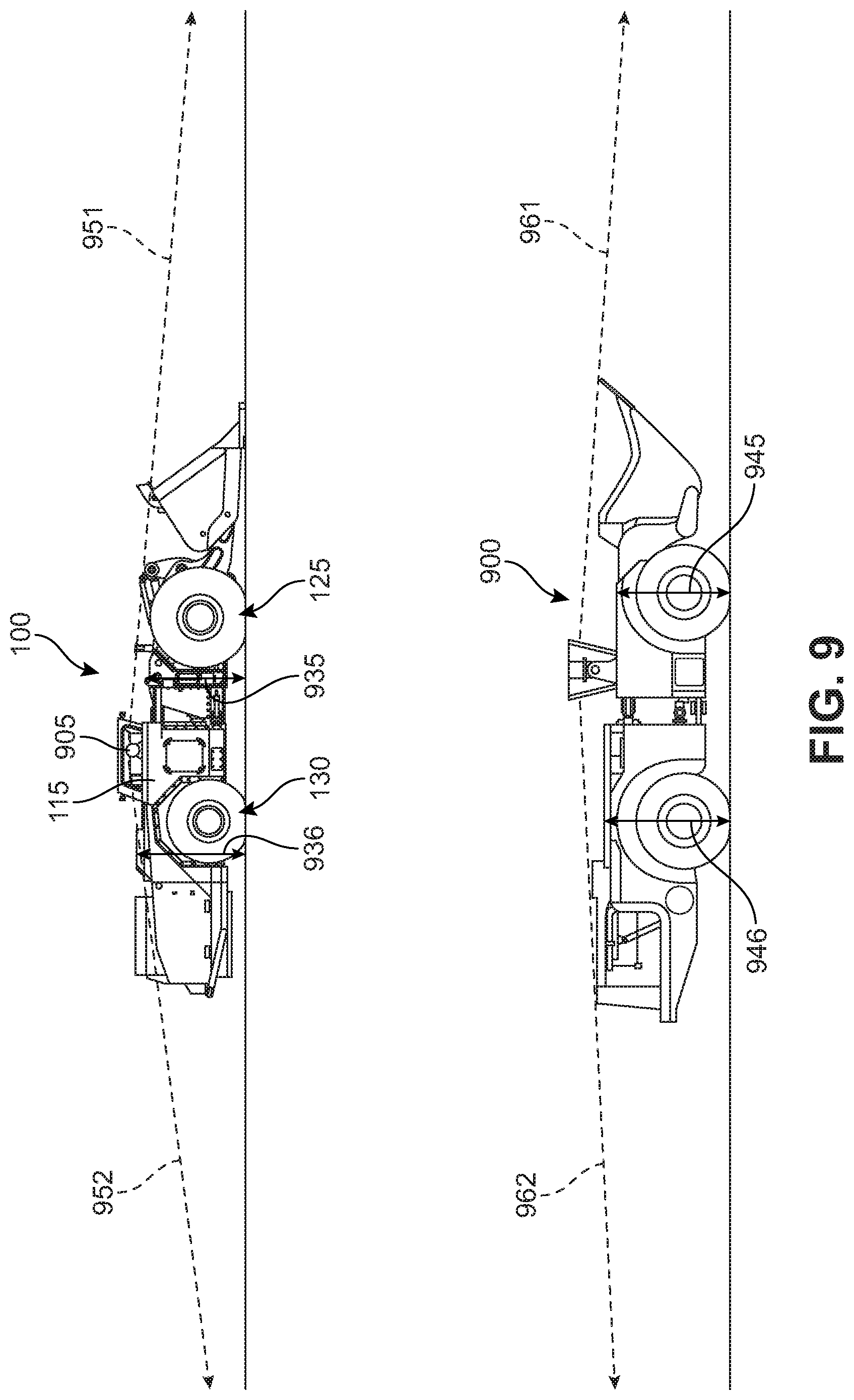
[0021] FIG. 9 shows a comparison of the degree of visibility available in two different mining vehicles, according to an embodiment;
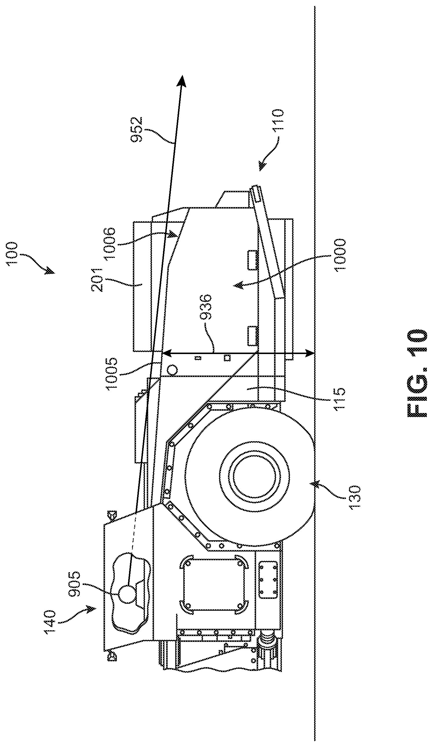
[0022] FIG. 10 is a schematic illustration of a left side view of the rear portion of the vehicle shown in FIG. 1; and
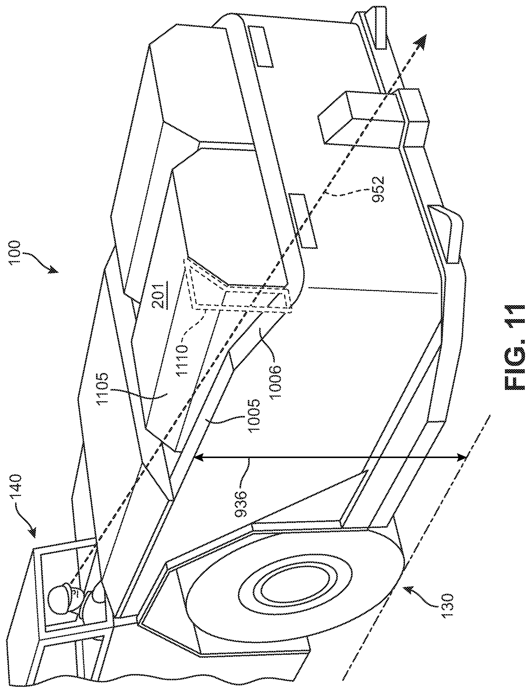
[0023] FIG. 11 is a schematic illustration of a rear perspective view showing a window of visibility along the rear driver's side of the vehicle shown in FIG. 1.
DETAILED DESCRIPTION
[0024] Electric mining machines are generally powered by onboard battery packs. The machines can be load-haul-dump (LHD) machines, scalers, graders, scoops, rock breakers, cutters, haulers or a combination. In general, electric mining machines are heavy duty vehicles engineered for the challenging subsurface environments and limited spaces powered by an onboard battery or other power source. The machines generally include a tool end, heavy-duty wheels and tires, an operator area, controls, and may include a removable power source mounted onboard the machine.
[0025] This disclosure is directed to an electric vehicle or machine. In general, as used herein, the term "electric vehicle" refers to a vehicle that uses electrical power for propulsion purposes, at least in one mode of operation. Thus, electric vehicles include all-electric vehicles (e.g., a vehicle with a traction motor and only an onboard electrical energy storage device or mechanism for receiving electric energy from an off-board source, such as an overhead catenary or powered rail), hybrid-electric vehicles (e.g., a vehicle with a traction motor, an energy storage device, hydraulic propulsion, and a fuel engine, fuel cell, or the like for charging the energy storage device and/or directly generating power for running the traction motor), dual-mode vehicles (e.g., a vehicle with an engine-only mode of operation and an electricity-only mode of operation, or a vehicle with a first mode of operation where traction electricity is provided by an engine and a second mode of operation where traction electricity is provided by another source), diesel-electric and other engine-electric vehicles (e.g., a vehicle with an engine that generates electrical power for running a traction motor), and combinations and variants thereof. Electric vehicles may have one traction motor, or plural traction motors; "traction motor" refers to a motor of sufficient size and capacity to move a vehicle of sufficient size for the designated operation.
[0026] In some embodiments, the vehicle interface equipment of the wayside stations may comprise: "plug in" modules, e.g., the vehicle plugs into a receptacle of the wayside station, for receiving electrical power from the station; a continuous power interface by which a vehicle can receive off-board power while moving, such as the aforementioned catenary line or third rail; or the like.
[0027] In some embodiments, the disclosed vehicle may be configured for mining. For example, in some embodiments, the disclosed vehicle may be a working vehicle with a scoop or bucket. For instance, in some embodiments, the disclosed vehicle may be an electrically powered LHD.
[0028] In some embodiments, the vehicle may be fully electric, and thus, may use only a battery to power the vehicle in place of a conventional diesel engine. In some cases, the vehicle may be used in mining operations. In order to make the vehicle better suited for mining conditions, the vehicle is designed with a substantially smaller form factor compared to conventional vehicles. Because the vehicle is all electric, there is a lot of space saved compared to diesel machines that require an engine, transmission, torque converter, etc.
[0029] The vehicle has been designed with a small footprint--including a reduction in length as well as a reduction in vertical height, compared to similar diesel vehicles. In addition, the vehicle takes advantage of the electric power train to implement some features sized for a larger payload and other features sized for a smaller payload. For example, the bucket and front tires may be sized for a larger payload, whereas the vehicle frame and rear tires may be sized as they would be in a vehicle having a substantially lower payload capacity. For example, in some embodiments, the bucket and front tires may be sized and configured to handle at least approximately 10 metric tons, whereas the vehicle frame and rear tires may be sized similarly to a vehicle configured to handle a maximum payload capacity of no more than approximately 7 metric tons. Because of the smaller sized frame and rear tires, the vehicle may have the visibility of a (smaller) 7 ton (payload) vehicle, but the payload capacity of a 10 ton (payload) vehicle. Because the drivetrain is electric, the frame need not be as large, and thus may have a reduced maximum height. In addition, separate electric motors may be used for each axle, enabling the front tires and rear tires to be operated independently of one another. Because of the independence between the axles, the front tires and rear tires may have different sizes without the need of significant differentials/gearing to ensure that the tires turn at the same speed despite differences in diameter.
[0030] For purposes of clarity the following terms may be used in the detailed description and the specification. The term "payload capacity," or simply capacity, is used to characterize the amount of material that can be held in the scoop or bucket of a vehicle, and that can also be lifted by the bucket and transported. The payload capacity may also be referred to as the "tramming capacity." As discussed in further detail below, a vehicle may also be characterized by the ratio of its payload capacity with some other characteristic such as its length, height, footprint, volume, density, tire size, visibility, or other characteristic.
[0031] The disclosed vehicle may include standard provisions for a mining vehicle, such as wheels and a bucket (or scoop). The vehicle may also include provisions for powering the wheels and bucket. For example, the vehicle may include two or more electric motors, which are powered by one or more onboard battery packs.
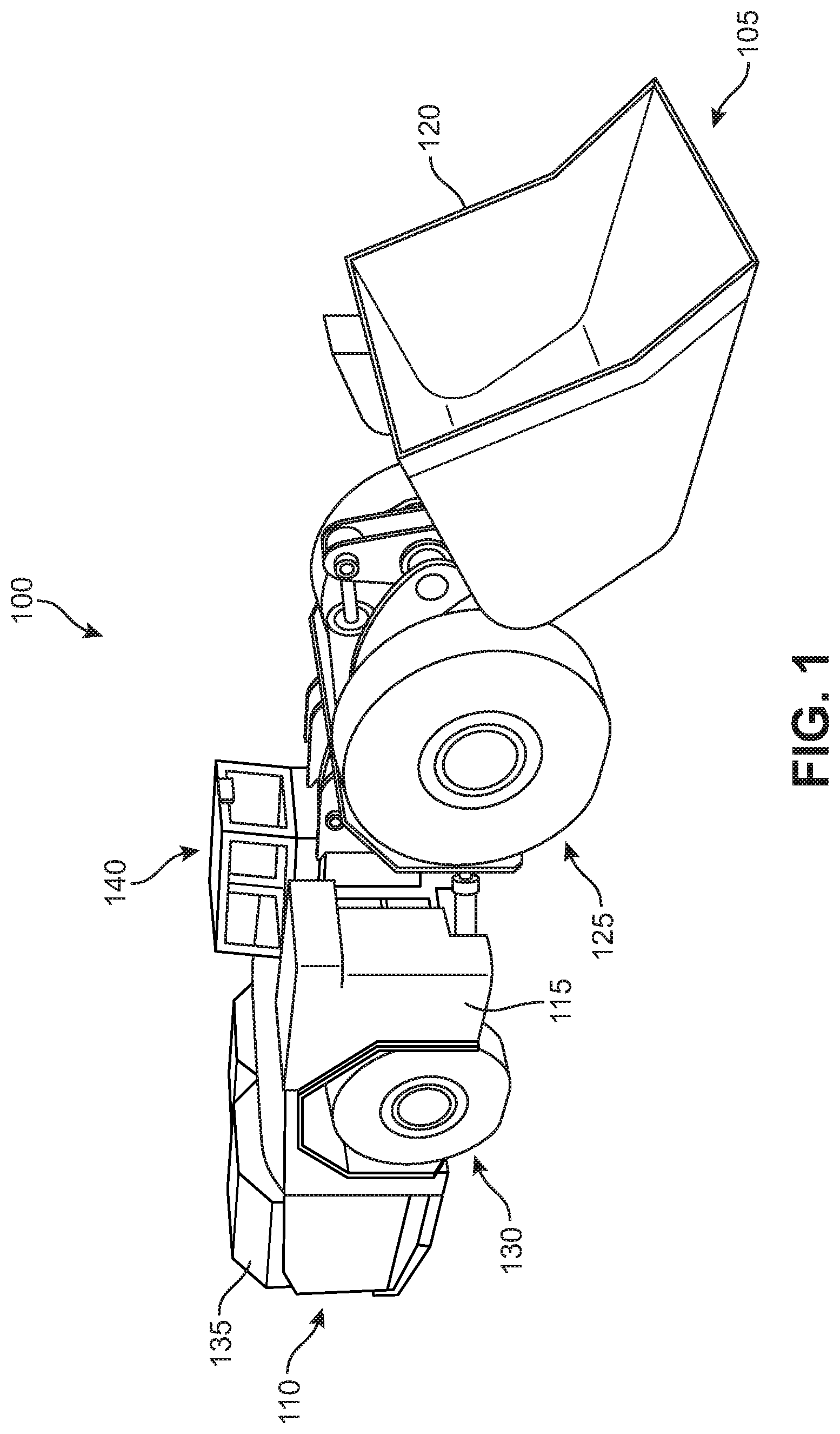
[0032] FIG. 1 is a schematic illustration showing a front perspective view of an embodiment of an electric mining vehicle 100. As shown in FIG. 1, vehicle 100 may include a frame 115 defining a front end 105 and a rear end 110 of vehicle 100. In some embodiments, frame 115 may be provided in two sections configured to articulate relative to one another (see FIG. 7). In addition, vehicle 100 may include a set of wheels, including a pair of front tires 125 proximate front end 105 of vehicle 100, and a pair of rear tires 130 proximate rear end 110 of vehicle 100.
[0033] As shown in FIG. 1, vehicle 100 may include an operator cockpit. In order to shield the operator from debris and overhead obstacles, the cockpit may include a canopy 140. Canopy 140 may include numerous windows or openings in order to permit substantially unimpeded visibility 360 degrees around the cockpit location.
[0034] As also shown in FIG. 1, vehicle 100 may include a work implement, such as a bucket 120 connected to frame 115 at the front end of the vehicle and configured to receive a payload. In different embodiments, the payload capacity of vehicle 100 could vary. In some embodiments, vehicle 100 could have a payload capacity of approximately 10 metric tons.
[0035] Bucket 120, front tires 125, and/or rear tires 130 may be powered by an electric power source 135. In some embodiments, electric power source 135 may include one or more rechargeable batteries. In some embodiments, the batteries may be removably attached to the vehicle.
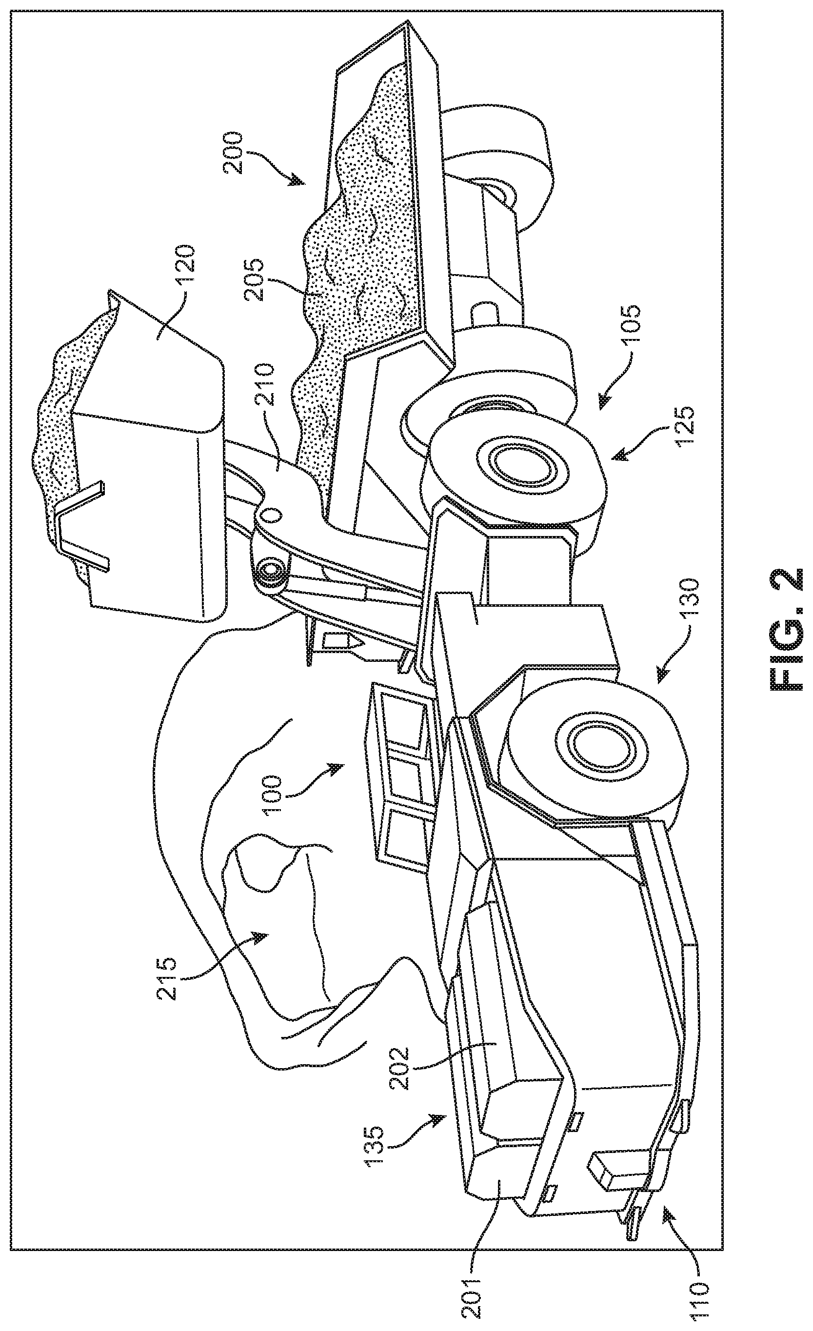
[0036] FIG. 2 is a schematic illustration showing a rear perspective view of the mining vehicle of FIG. 1. FIG. 2 shows vehicle 100 loading a hauling vehicle 200 with a payload of material 205. In particular, FIG. 2 shows vehicle 100 raising bucket 120 via a boom linkage 210 in order to load material 205 into the bed of hauling vehicle 200. FIG. 2 also shows vehicle 100 and hauling vehicle 200 in a mine shaft 215 thereby providing environmental context.
[0037] In some embodiments, the electric power source may include at least one battery pack including at least one battery cell. For example, as shown in FIG. 2, in some embodiments, electric power source 135 may include one or more batteries. Such batteries may be any type of rechargeable battery suitable for use in a mine vehicle. In some embodiments, vehicle 100 may include a first battery pack 201 and a second battery pack 202 configured to drive the tires of vehicle 100. Each battery pack may include a plurality of modules, and each module may include a plurality of cells. In addition to first battery pack 201 and second battery pack 202, vehicle 100 may include a tramming battery pack (see FIG. 3). The tramming battery pack may be configured to move vehicle 100 while first battery pack 201 and second battery pack 202 are being swapped for recharging. In some embodiments, first battery pack 201, second battery pack 202, and/or the tramming battery pack may be a lithium iron phosphate battery. In some embodiments, different types of batteries may be utilized.
[0038] In some embodiments, the combined output of first battery pack 201 and second battery pack 202 may be approximately 265 kWh. Further, the tramming battery may have an output of 24 kWh. The electric power source may be used to power one or more electric motors in order to propel the vehicle. Thus, the vehicle may include an electric propulsion system. The electric propulsion system may include a first electric motor configured to deliver power to the front pair of wheels and a first electric power source configured to deliver power to the first electric motor. In addition, the electric propulsion system may include a second electric motor configured to deliver power to the rear pair of wheels and a second electric power source configured to deliver power to the second electric motor.
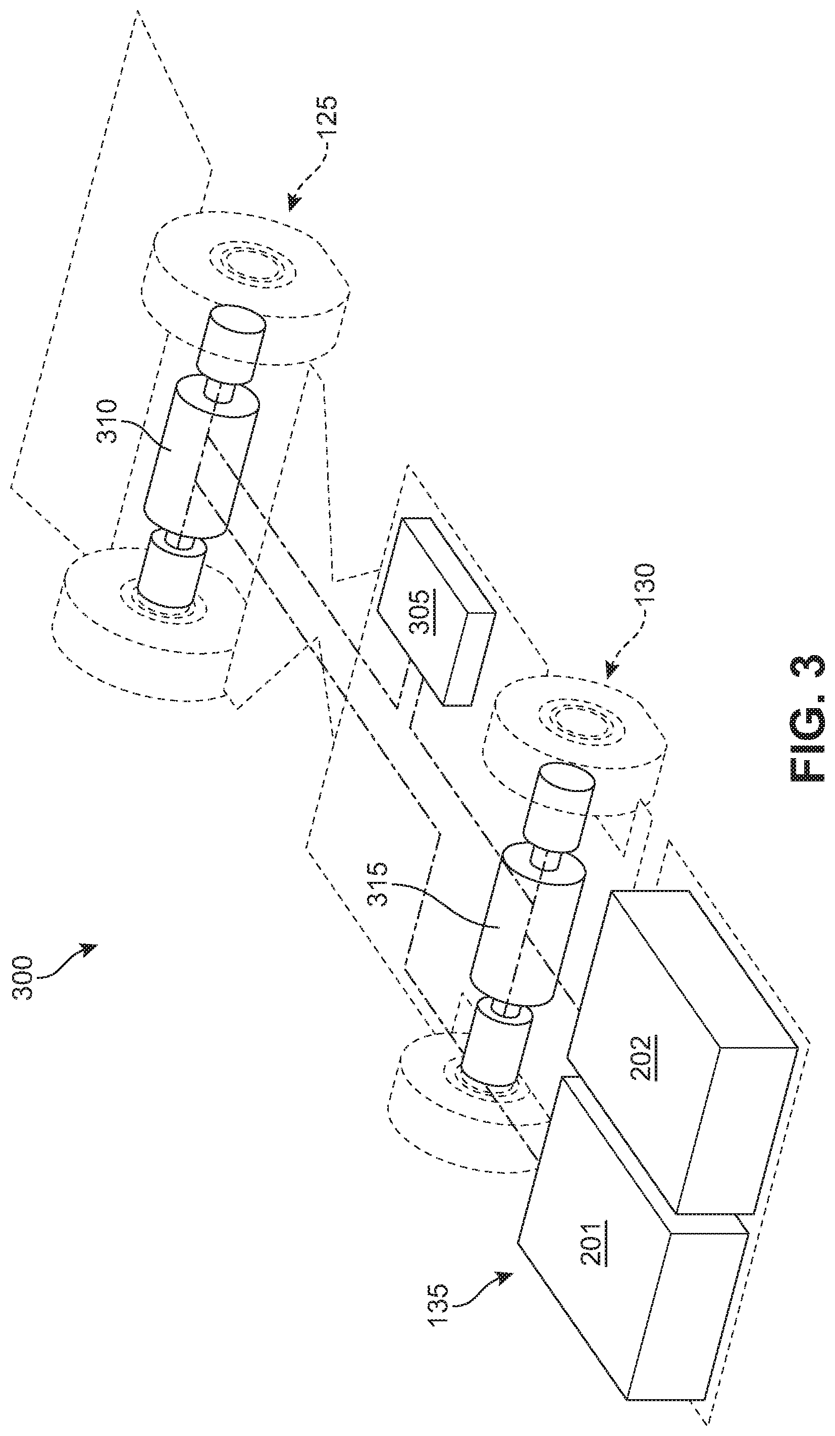
[0039] FIG. 3 is a schematic illustration of a dual motor electric power train system according to an exemplary embodiment. As shown in FIG. 3, an electric propulsion system 300 may include electric power source 135, including first battery pack 201 and second battery pack 202, as well as a tramming battery 305. In addition, electric propulsion system 300 may include a first electric motor 310 configured to deliver power to front tires 125. Further, electric propulsion system 300 may include a second electric motor 315 configured to deliver power to rear tires 130. In some embodiments, the combined output of first battery pack 201 and second battery pack 202 may be used to power first motor 310 and/or second motor 315. In some embodiments, first battery pack 201 may be configured to deliver power to first motor 310, and second battery pack 202 may be configured to deliver power to second motor 315.
[0040] In some embodiments, the traction motors (first electric motor 310 and second electric motor 315) may have a combined peak torque of approximately 4100 Newton-meters. In some embodiments, the traction motors may operate with a combined continuous power output capacity of 360 kW (483 hp) and a peak combined power of 540 kW (724 hp).
[0041] As discussed above, because separate electric motors may be used for each axle, the front wheels and rear wheels may be operated independently of one another, and thus, the front tires may be sized differently than the rear tires. For example, the front tires may be larger than the rear tires. The larger front tires permit the vehicle to carry a heavier load in the bucket, while the smaller rear tires enable the frame of the vehicle to be made smaller, thereby providing better visibility for the operator. In some embodiments, the front tires may be 40% or more larger than the rear tires. For example, in some embodiments, the front tires may be sized to handle a payload of approximately 10 metric tons and the rear tires may have a size corresponding to tires of a vehicle configured to handle a payload of approximately 7 metric tons.
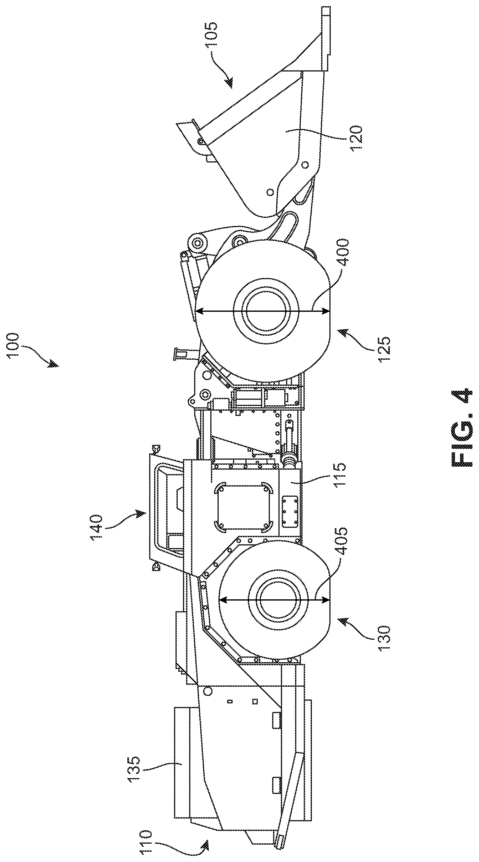
[0042] FIG. 4 is a schematic illustration showing a right side view of the mining vehicle of FIG. 1. As shown in FIG. 4, vehicle 100 may include differently sized tires. For example, front tires 125 may have a first diameter 400 and rear tires 130 may have a second diameter 405 that is substantially smaller than first diameter 400. For example, in some embodiments, front tires 125 may be sized to handle a payload of approximately 10 metric tons, while rear tires 130 may be sized to handle a payload of approximately 7 metric tons. For example, in such cases, front tires 125 may have a size of 18.00R25, and may have a diameter of approximately 1615 mm, a section width of approximately 498 mm, a load index of approximately 186, and a max load of 9500 kg (all specifications typical of an LHD with a 10 metric ton payload capacity). In contrast, rear tires 130 may have a size of 17.5R25, and may have a diameter of approximately 1348 mm, a section width of approximately 445 mm, a load index of approximately 170, and a max load of approximately 6000 kg (all specifications typical of an LHD with a 7 metric ton payload capacity). Comparing these parameters of the two tire sizes, the front tires have approximately 20% larger diameter, approximately 12% larger section width, approximately 10% higher load index, and approximately 58% higher max load.
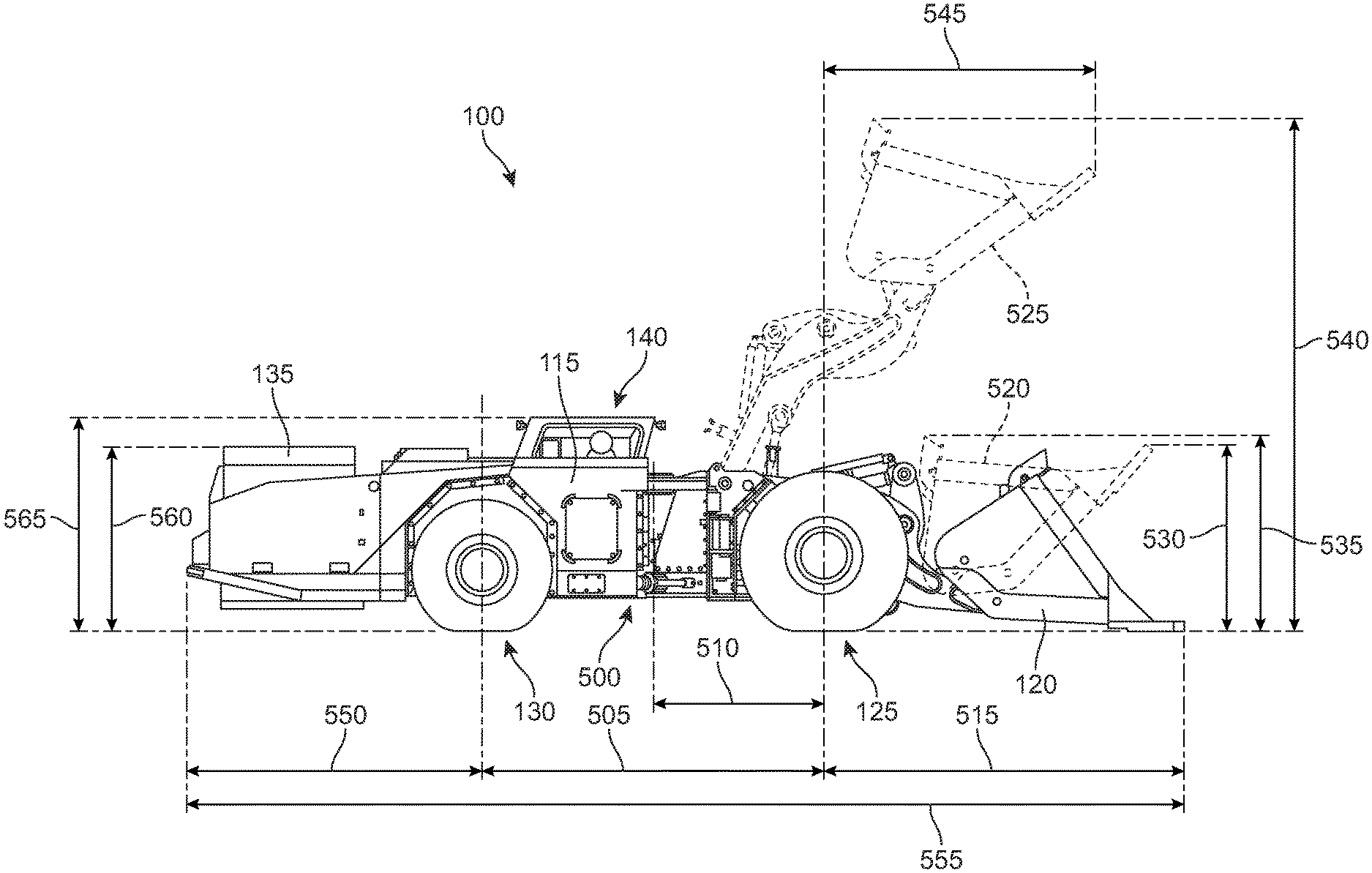
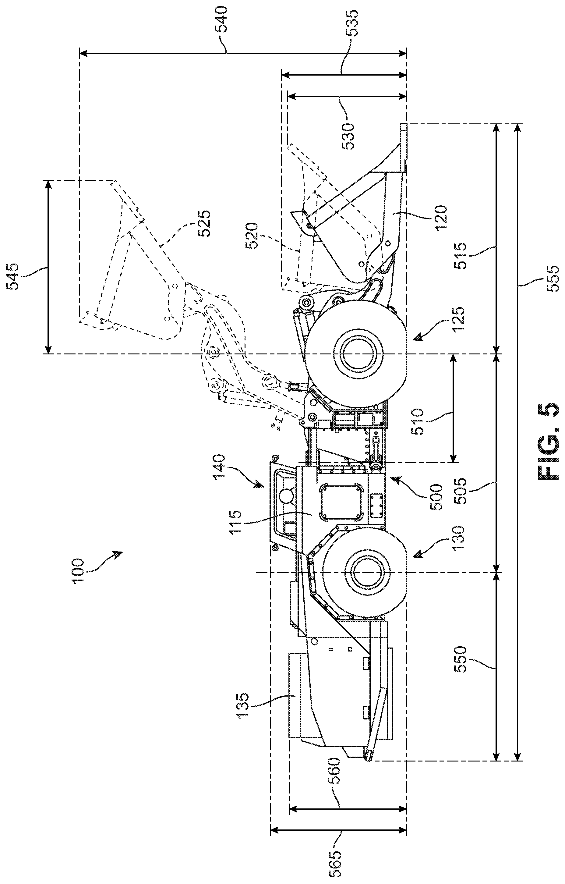
[0043] FIG. 5 is a schematic illustration showing a right side view of the mining vehicle of FIG. 1 with the payload bucket in various positions. FIG. 5 shows various dimensions of vehicle 100. As discussed above, different components of vehicle 100 may be sized to handle different payloads. In particular, bucket 120 and front tires 125 may be sized to handle larger payloads (e.g., approximately 10 metric tons), whereas frame 115 and rear wheels 130 may be sized much smaller. The smaller size of rear wheels 130 enables the rear portion of frame 115 to be made smaller. In addition, at least one hydraulic lift cylinder of the bucket boom linkage may be mounted to the frame using a trunnion. By using a trunnion mounted cylinder, a greater maximum bucket reach/height may be achieved with a frame having a shorter maximum height than would otherwise be required to reach the desired height. Accordingly, the bucket may be raised to a height corresponding to a typical 10 ton LHD and the frame proximate the front end of the vehicle may have a maximum height that corresponds with a typical 7 ton LHD. The trunnion mounted cylinder is discussed in further detail below with regard to FIG. 8.
[0044] As shown in FIG. 5, vehicle 100 may include a center pivot 500 enabling frame 115 to articulate. FIG. 5 also shows bucket 120 in various positions, including a fully lowered position illustrated with solid lines. Bucket 120 is also shown in a curled position indicated by a first dashed outline 520, as well as a fully raised position indicated by a second dashed outline 525.
[0045] FIG. 5 illustrates various dimensions of vehicle 100, which will be discussed both generally and specifically below. Exemplary corresponding dimensions of a benchmark vehicle are also discussed where relevant. It will be noted that, for both vehicle 100 and athe benchmark vehicle, some of the dimensions discussed may vary due to the use of slightly different sized or shaped buckets, which are interchangeable as accessories.
[0046] Vehicle 100 essentially may have the overall size, in most dimensions, of an LHD having a 7 metric ton payload capacity, but may have features that enable it to have the payload capacity and maximum vertical bucket reach of an LHD with a 10 metric ton payload capacity. To support the higher payload, larger tires may be used in the front of vehicle 100. To provide the increased vertical bucket reach without increasing frame or chassis height, trunnion mounted hydraulic cylinders may be used to raise and lower the bucket. Also, in order to facilitate having different sized front and rear tires, separate electric motors may be used on the front and rear axles. Accordingly, vehicle 100 may have a 10 metric ton payload capacity, but the visibility, maneuverability, light weight, and overall compact size of an LHD with a 7 metric ton payload capacity. The following dimensions illustrate the smaller sizes of various aspects of vehicle 100 compared to a benchmark LHD having a 10 metric ton payload capacity.
[0047] As shown in FIG. 5, vehicle 100 may have a wheelbase 505 extending between the center points of the front and rear wheels. In some embodiments, wheelbase 505 may be approximately 3400 mm. For comparison, a benchmark LHD having a 10 metric ton payload capacity may have a wheelbase of approximately 3536 mm. In addition, the wheel centers may be positioned substantially equidistant from pivot 500. A dimension 510 illustrates a distance between pivot 500 and the center of front tires 125. In some embodiments, dimension 510 may be approximately 1700 mm (1768 mm for the benchmark LHD).
[0048] A dimension 515 indicates the distance between the center of front tires 125 and the tip of bucket 120 in the lowermost position. In some embodiments, dimension 515 may be approximately 3592 mm. A dimension 530 indicates the distance from the ground to the tip of bucket 120 when in the curled position. In some embodiments, dimension 530 may be approximately 1872 mm. A dimension 535 illustrates the distance from the ground to the rearward/upper portion of bucket 120 when in the curled position. In some embodiments, dimension 535 may be approximately 2145 mm. Also, a dimension 540 illustrates the distance between the ground and the uppermost portion of bucket 120 when in the raised position. In some embodiments, dimension 540 may be approximately 5100 mm. These dimensions related to bucket 120 may correspond with a typical 10 ton LHD. For example, the max height corresponding to dimension 540 in the benchmark LHD is approximately 5114 mm, nearly the same as the corresponding dimension for vehicle 100 (5100 mm).
[0049] In addition, a dimension 550 illustrates a distance between the center of rear tires 130 and the rearward most portion of vehicle 100. In some embodiments, dimension 550 may be approximately 2941 mm (3055 mm for the benchmark LHD). Accordingly, dimension 505, dimension 515, and dimension 550, added together, equal the total length of vehicle 100, which is also illustrated as a dimension 555. In some embodiments, dimension 555 may be approximately 9933 mm (9955 mm or longer for the benchmark LHD, depending on how large of a bucket is used). A dimension 560 illustrates a height of a rear portion of frame 115. In some embodiments, dimension 560 may be approximately 1846 mm (1890 mm for the benchmark LHD). Also, a dimension 565 illustrates the overall height of vehicle 100 with bucket 120 in the lowered position (i.e., from the ground to the top of canopy 140). In some embodiments, dimension 565 may be approximately 2149 mm (2400 mm for the benchmark LHD). These dimensions relating to the rearward part of vehicle 100, excepting the overall length 555, may correspond with those of a typical 7 ton LHD. By comparison, the dimensions for the benchmark LHD, in parentheses above, are substantially larger, thus illustrating the relative compactness of vehicle 100 as compared to a benchmark vehicle having the same payload capacity.
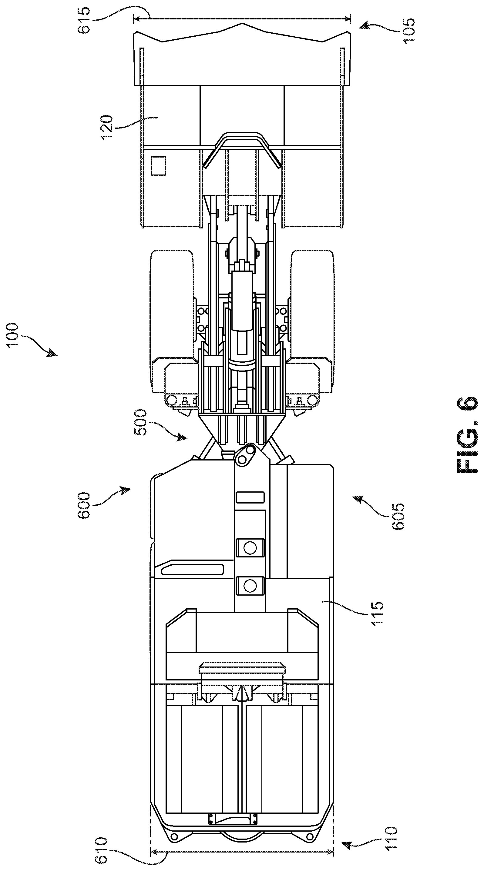
[0050] FIG. 6 is a schematic illustration of a top side view of the mining vehicle of FIG. 1. In FIG. 6, vehicle 100 is illustrated with rear end 110 located to the left and front end 105 illustrated to the right. FIG. 6 also shows that vehicle 100 has a left side 600 and a right side 605. The width of frame 115 between left side 600 and right side 605 is illustrated as a dimension 610. In some embodiments, dimension 610 may be approximately 2195 mm (2404 mm for the benchmark LHD). In addition, as shown in FIG. 6, bucket 120 may be slightly wider than frame 115, as illustrated by a dimension 615. In some embodiments, dimension 615 may be approximately 2607 mm (2723 mm for the benchmark LHD; again depending on the size of the bucket used).
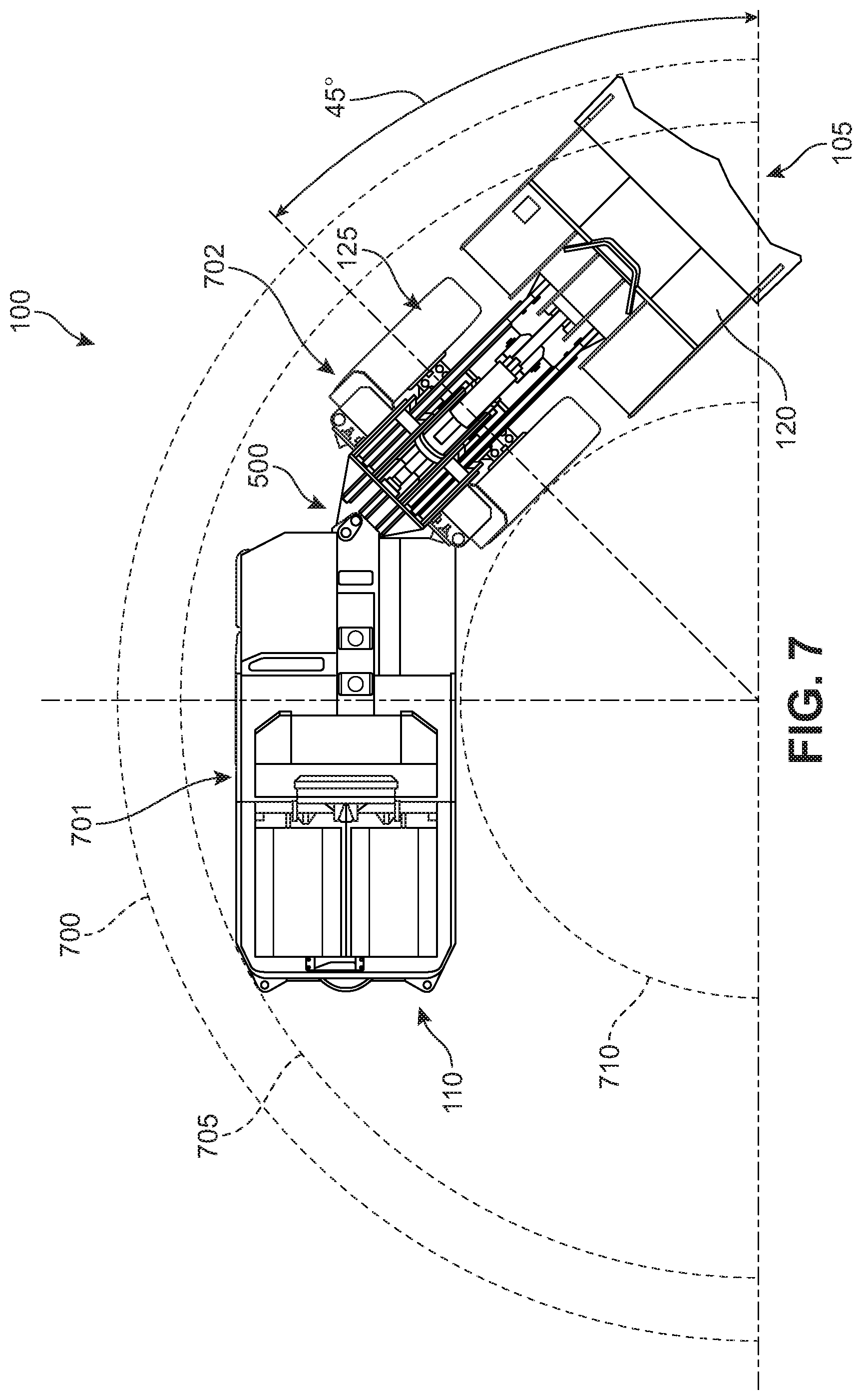
[0051] FIG. 7 is a schematic illustration of a top side view of the mining vehicle of FIG. 1 in an articulating condition and showing the turning radius. In particular, a first body portion 701 is angled with respect to a second body portion 702 at angle of 45 degrees. In some embodiments, the maximum angle of articulation may vary between 30 and 50 degrees. In addition, the inner turning path has radius 710. The outer turning path has radius 705. In one embodiment, radius 705 has a value of approximately 5768 mm. Also, in one embodiment, radius 710 has a value of approximately 3005 mm (3291 mm for the benchmark LHD). Of course radius 705 and/or radius 710 could be varied in other embodiments as the length and/or width of the vehicle are varied, and/or as other features are modified (such as the mechanical linkage between first body portion 701 and second body portion 702). Further, FIG. 7 illustrates a bucket path radius 700. In some embodiments, bucket path radius 700 may be approximately 6420 mm (6638 mm for the benchmark LHD). It will be noted that both the outer and inner turning radii of vehicle 100 are substantially smaller than those of the benchmark LHD, illustrating the increased maneuverability of vehicle 100 in comparison.
[0052] In some embodiments, the disclosed vehicle may have a maximum vertical bucket reach that corresponds with a vehicle having a larger payload capacity, and a maximum frame height proximate the front portion of the chassis that corresponds with a vehicle having a substantially smaller payload capacity. These divergent component sizes may be facilitated by mounting one or more hydraulic lift cylinders of the bucket boom assembly onto the frame using a trunnion.
[0053] FIG. 8 shows the vertical bucket reach and chassis height of the vehicle shown in FIG. 1 in comparison with a traditional/benchmark vehicle configured to haul the same payload. As shown in FIG. 8, vehicle 100 has bucket 1210 raised to a maximum height 815, and a benchmark vehicle 800 has its bucket 820 also raised to a maximum height, which is the same as the maximum reach of bucket 120 of vehicle 100. It will also be noted that the size and shape of bucket 820 is substantially similar to bucket 120, and thus, the two buckets have substantially the same payload capacity, e.g., 10 metric tons. Further, in order to support the same payload, the two vehicles may have the same size tires. That is, height 805 illustrates the height of front tire 125 of vehicle 100, and a front tire 812 of benchmark vehicle 800 may have a height 810, which may be substantially the same as height 805 of front tire 125 of vehicle 100.
[0054] However, despite the similarities between the buckets, reach, and tire sizes of vehicle 100 and benchmark vehicle 800, the frames of the two vehicles may be differently sized. For example, as shown in FIG. 8, frame 115 of vehicle 100 may have a maximum height 825 proximate to the front end of vehicle 100 where front tire 125 is attached. Benchmark vehicle 800 may have a frame 835 with a maximum height 830. As shown in FIG. 8, height 825 may be substantially smaller than height 830. For example, height 825 of vehicle 100 may correspond with the frame height of an LHD with a 7 ton payload capacity. In contrast, since benchmark vehicle 800 is a typical 10 ton LHD, frame height 830 is typical for an LHD having a 10 ton payload capacity.
[0055] The bucket reach of a 10 ton vehicle despite the frame height of a 7 ton vehicle is achieved, at least in part, by use of a trunnion mounting for hydraulic lift cylinder 845. For example, as shown in FIG. 8, lift cylinder 845 is mounted at a pivot 850 that resides between the endpoints of lift cylinder 845. Accordingly, a longer lift cylinder may be used despite the small frame sizing in the area of the chassis proximate to the bucket actuation linkage.
[0056] The disclosed vehicle may have an improved line of sight compared to similar vehicles having the same or substantially the same payload capacity. This improved line of sight is achieved by way of the reduced frame height in the front and rear portions of the vehicle. In particular, the use of smaller tires in the rear and a trunnion mounted lift cylinder in the front enables shorter frame dimensions to be used at both ends of the vehicle. In addition, other accommodations, such as angled battery pack surfaces and angled frame surfaces provide a viewing path along the driver's side of the vehicle.
[0057] As used herein, a sightline is a line of visibility between a driver/operator of a vehicle and some location away from the vehicle. If a driver/operator has a clear sightline to a location, then the location is visible. The term "ground visibility distance" refers to the horizontal distance between the cab of a vehicle (i.e., where the operator sits) and the nearest location on the ground at which a driver has a sightline to the ground (i.e., the shortest possible horizontal distance for which the driver can see the ground).
[0058] FIG. 9 shows a comparison of the degree of visibility available in two different mining vehicles, according to an embodiment. As shown in FIG. 9, an operator 905 of vehicle 100 has a forward sightline 951. In addition, operator 905 has a rearward sightline 952. As shown in FIG. 9, a benchmark vehicle 900 may have a forward sightline 961 and a rearward sightline 962. As illustrated in FIG. 9, the sightlines of benchmark vehicle 900 are substantially longer than those of vehicle 100. That is, forward sightline 961 of vehicle 900 is significantly longer than forward sightline 951 of vehicle 100. Similarly, rearward sightline 962 of vehicle 900 is significantly longer than rearward sightline 952 of vehicle 100. It will also be noted that vehicle 100 has a front frame height 935 that is substantially lower than front frame height 945 of benchmark vehicle 900. Further, vehicle 100 has a rear frame height 936 that is substantially lower than rear frame height 946 of benchmark vehicle 900. The lower frame heights of vehicle 100, as compared to a benchmark vehicle having the same capacity, provide improved visibility in both the forward and rearward directions.
[0059] FIGS. 10 and 11 show how the angled surfaces of frame 115 and battery pack 201 provide a window of visibility in the rearward direction, down the driver's side of vehicle 100. FIG. 10 is a schematic illustration of a left side view of the rear portion of the vehicle shown in FIG. 1. As shown in FIG. 10, a rear portion 1000 of frame 115 may include a first angled surface 1005 and a second angled surface 1006 that both slope away from operator 905. Because of these angled surfaces along the driver's side of the vehicle, operator 905 can see the ground much closer to the rear of the vehicle than if the frame were horizontal all the way to rear end 110 of vehicle 100. Sightline 952 indicates how operator 905 can see down the side of vehicle 100 along first battery pack 201.
[0060] In addition to the angled surfaces of frame 115, the battery packs may also include some angled surfaces that improve rearward visibility from the cockpit. FIG. 11 is a schematic illustration of a rear perspective view showing a window of visibility along the rear driver's side of the vehicle shown in FIG. 1. As shown in FIG. 11, first battery pack 201 may include a third angled surface 1105. When combined with first angled surface 1005 and second angled surface 1006 of frame 115, these three angled surfaces provide a path of visibility down the rear, driver's side of vehicle 100, as illustrated by a dashed line 1110, through which sightline 952 passes.
[0061] While various embodiments of the invention have been described, the description is intended to be exemplary, rather than limiting, and it will be apparent to those of ordinary skill in the art that many more embodiments and implementations are possible that are within the scope of the invention. Any element of any embodiment may be substituted for another element of any other embodiment or added to another embodiment except where specifically excluded. Accordingly, the invention is not to be restricted except in light of the attached claims and their equivalents. Also, various modifications and changes may be made within the scope of the attached claims.
* * * * *
D00000
D00001
D00002
D00003
D00004
D00005
D00006
D00007
D00008
D00009
D00010
D00011
XML
uspto.report is an independent third-party trademark research tool that is not affiliated, endorsed, or sponsored by the United States Patent and Trademark Office (USPTO) or any other governmental organization. The information provided by uspto.report is based on publicly available data at the time of writing and is intended for informational purposes only.
While we strive to provide accurate and up-to-date information, we do not guarantee the accuracy, completeness, reliability, or suitability of the information displayed on this site. The use of this site is at your own risk. Any reliance you place on such information is therefore strictly at your own risk.
All official trademark data, including owner information, should be verified by visiting the official USPTO website at www.uspto.gov. This site is not intended to replace professional legal advice and should not be used as a substitute for consulting with a legal professional who is knowledgeable about trademark law.