Placement Of Abrasive Particles For Achieving Orientation Independent Scratches And Minimizing Observable Manufacturing Defects
Jusuf; Vincent ; et al.
U.S. patent application number 16/635427 was filed with the patent office on 2020-05-21 for placement of abrasive particles for achieving orientation independent scratches and minimizing observable manufacturing defects. The applicant listed for this patent is 3M INNOVATIVE PROPERTIES COMPANY. Invention is credited to James P. Endle, Vincent Jusuf, Richard L. Rylander, Michael J. Wald.
| Application Number | 20200156215 16/635427 |
| Document ID | / |
| Family ID | 63013069 |
| Filed Date | 2020-05-21 |


| United States Patent Application | 20200156215 |
| Kind Code | A1 |
| Jusuf; Vincent ; et al. | May 21, 2020 |
PLACEMENT OF ABRASIVE PARTICLES FOR ACHIEVING ORIENTATION INDEPENDENT SCRATCHES AND MINIMIZING OBSERVABLE MANUFACTURING DEFECTS
Abstract
The present invention includes an abrasive tool comprising a substrate and plurality of abrasive grains arranged in a pseudo-random pattern on the substrate. The abrasive grains cover in the range of 10% to 30% of the substrate surface, and in some instances, the arrangement of abrasive grains demonstrate improved orientation independence and homogeneity in distribution of abrasive grains.
| Inventors: | Jusuf; Vincent; (Minneapolis, MN) ; Wald; Michael J.; (Woodbury, MN) ; Endle; James P.; (New Richmond, WI) ; Rylander; Richard L.; (Stillwater, MN) | ||||||||||
| Applicant: |
|
||||||||||
|---|---|---|---|---|---|---|---|---|---|---|---|
| Family ID: | 63013069 | ||||||||||
| Appl. No.: | 16/635427 | ||||||||||
| Filed: | July 3, 2018 | ||||||||||
| PCT Filed: | July 3, 2018 | ||||||||||
| PCT NO: | PCT/IB2018/054924 | ||||||||||
| 371 Date: | January 30, 2020 |
Related U.S. Patent Documents
| Application Number | Filing Date | Patent Number | ||
|---|---|---|---|---|
| 62538895 | Jul 31, 2017 | |||
| Current U.S. Class: | 1/1 |
| Current CPC Class: | B24D 11/001 20130101; B24D 3/00 20130101; B24D 3/28 20130101; B24D 11/00 20130101 |
| International Class: | B24D 11/00 20060101 B24D011/00; B24D 3/28 20060101 B24D003/28 |
Claims
1. An abrasive tool comprising a substrate and plurality of abrasive grains arranged in a pseudo-random pattern on the substrate, wherein the abrasive grains cover in the range of 10% to 30% of the substrate surface and wherein the arrangement of abrasive grains has a score of 20% or less on the Orientation Independence Test and has a score in the range of 0.7 to 0.9 in the Local Homogeneity Index Test.
2. The abrasive tool of claim 1, wherein the arrangement of abrasive grains has a score of 10% or less on the Orientation Independence Test.
3. The abrasive tool of claim 1, wherein the abrasive grains cover 10% to 15% of the surface substrate.
4. The abrasive tool of claim 1, wherein the substrate comprises a lofty non-woven material.
5. The abrasive tool of claim 4, wherein the lofty non-woven material comprises a densified surface.
6. The abrasive tool of claim 1, wherein the abrasive grains are at least one of: single abrasive grits, cutting points, and composites comprising a plurality of abrasive grits, and combinations thereof.
7. The abrasive tool of claim 6 wherein the composites comprise a plurality of abrasive grits in a resin.
8. The abrasive tool of claim 1, wherein the abrasive grains are printed onto the substrate.
9. The abrasive tool of claim 1, wherein the average abrasive grain height from the surface of the substrate is in the range of 0.25 mm to 1.5 mm.
10. The abrasive tool of claim 1, wherein the pseudo-random pattern comprises clusters of abrasive grains.
11. The abrasive tool of claim 1, wherein the substrate is selected from the group consisting of paper, woven fabrics, nonwoven fabrics, calendared nonwoven fabrics, polymeric films, stitchbonded fabrics, open cell foams, closed cell foams, and combinations thereof.
12. The abrasive tool of claim 1, wherein the substrate comprises an open cell foam or a closed cell foam laminated to a substrate selected from the group consisting of paper, woven fabrics, nonwoven fabrics, calendared nonwoven fabrics, polymeric films, stitchbonded fabrics, open cell foams, closed cell foams, and combinations thereof.
13. The abrasive tool of claim 1, wherein the pseudo-random pattern is a pseudo-poisson pattern.
14-24. (canceled)
Description
FIELD OF THE INVENTION
[0001] The present invention relates to the placement of abrasive features on an abrasive work tool.
BACKGROUND
[0002] Tools with abrasive features can be used for a variety of applications, including grinding, polishing, abrading, finishing, scouring and scrubbing. Abrasive tools can be made with a variety of substrates including paper, woven fabrics, nonwoven fabrics, calendared nonwoven fabrics, polymeric films, stitch-bonded fabrics, open cell foams, closed cell foams, and combinations thereof. Abrasive tools can also include a variety of types of abrasive features or abrasive grains, including single abrasive grits, cutting points, and composites comprising a plurality of abrasive grits, and combinations thereof.
[0003] Abrasive features or grains can be arranged on a variety of surfaces in a variety of methods and arrangements. For example, some abrasive features are randomly distributed on a surface of a work tool and placed using coating, spraying, printing and solvent methods. Some abrasive features can be arranged in a pattern on a surface of a work tool.
[0004] The arrangement or placement of abrasive features can impact many aspects of the abrasive tool including the efficiency of cutting, the orientation in which the abrasive tool should be used, the scratch pattern left behind by the tool, and the manufacturing requirements for the abrasive tool. Improvements in abrasive tools to allow orientation independence, reduced visibility of scratch patterns, and ease of manufacturing are desired.
SUMMARY
[0005] The present disclosure provides several advantages over the state of the art. For example, the present disclosure provides for an abrasive tool that can perform more consistently in any mode of use, or when held at any orientation relative to a cut direction. The present disclosure also provides for an abrasive tool with abrasive grains arranged in a manner to reduce visibility of scratch patterns left on a work piece. The present disclosure further provides for placement of abrasive grains on an abrasive tool in a pseudo-random pattern such that slight manufacturing defects, such as missing or extra abrasive grains, are not noticeable to a user of the abrasive tool. The present disclosure also provides for an arrangement of abrasive features that provides for more even distribution of mass removal from a work piece. In some instances, the present disclosure allows for an arrangement of abrasive particles on a substrate in a way that can be visually pleasing independent of the orientation or shape of the substrate.
[0006] In one aspect, the present invention includes an abrasive tool comprising a substrate and plurality of abrasive grains arranged in a pseudo-random pattern on the substrate. The abrasive grains cover in the range of 10% to 30% of the substrate surface, and the arrangement of abrasive grains has a score of 20% or less on the Orientation Independence Test.
[0007] In another aspect, the present invention includes an abrasive tool comprising a substrate and a plurality of abrasive grains arranged in a pseudo-random pattern on the substrate, wherein the abrasive grains cover in the range of 10% to 30% of the substrate surface and wherein the arrangement of abrasive grains has a score in the range of 0.7 to 0.9 in the Local Homogeneity Index Test.
[0008] In some instances, the arrangement of abrasive grains has a score of 10% or less on the Orientation Independent Test.
[0009] In some instances, the abrasive grains cover 10% to 15% of the surface substrate.
[0010] In some instances, the substrate comprises a lofty non-woven material.
[0011] In some instances, the lofty non-woven material comprises a densified surface.
[0012] In some instances, the abrasive grains are at least one of: single abrasive grits, cutting points, and composites comprising a plurality of abrasive grits, and combinations thereof.
[0013] In some instances, the composites comprise a plurality of abrasive grits in a resin.
[0014] In some instances, the abrasive grains are printed onto the substrate.
[0015] In some instances, the average abrasive grain height from the surface of the substrate is in the range of 0.25 mm to 1.5 mm.
[0016] In some instances, the pseudo-random pattern comprises clusters of abrasive grains.
[0017] In some instances, the substrate is selected from the group consisting of paper, woven fabrics, nonwoven fabrics, calendared nonwoven fabrics, polymeric films, stitchbonded fabrics, open cell foams, closed cell foams, and combinations thereof.
[0018] In some instances, the substrate comprises an open cell foam or a closed cell foam laminated to a substrate selected from the group consisting of paper, woven fabrics, nonwoven fabrics, calendared nonwoven fabrics, polymeric films, stitchbonded fabrics, open cell foams, closed cell foams, and combinations thereof.
[0019] In some instances, the pseudo-random pattern is a pseudo-poisson pattern.
BRIEF DESCRIPTION OF THE DRAWINGS
[0020] The invention may be more completely understood in consideration of the following detailed description of various aspects of the invention in connection with the accompanying drawings, in which:
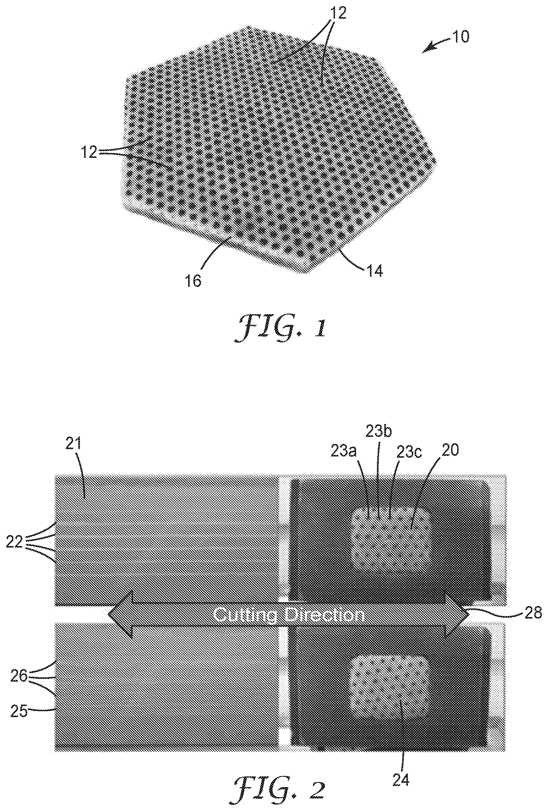
[0021] FIG. 1 shows an example of an abrasive tool with a regular hexagonal pattern of abrasive grains.
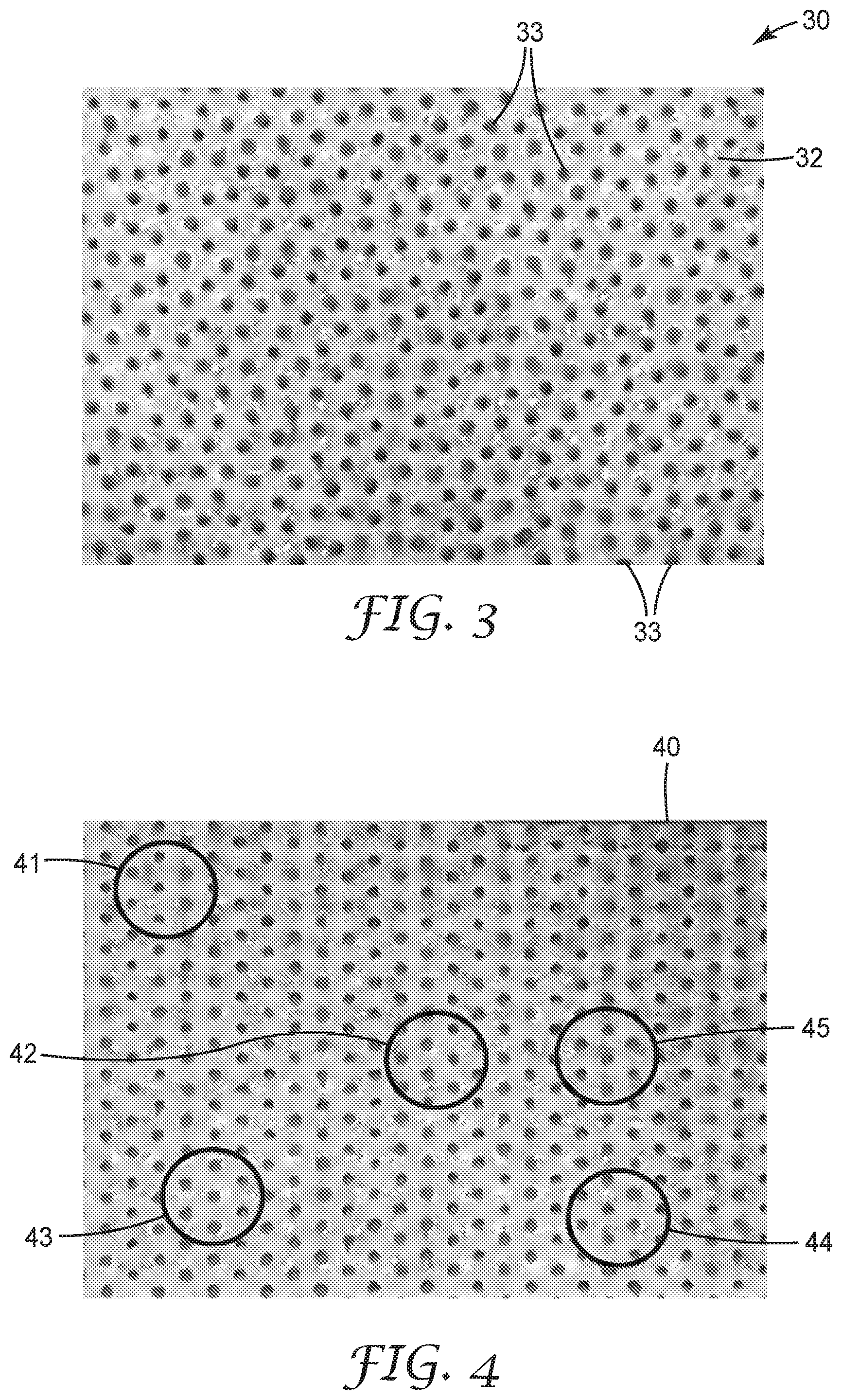
[0022] FIG. 2 shows an image of a scratch pattern formed by the prior art abrasive tool of FIG. 1 in two different cutting directions.
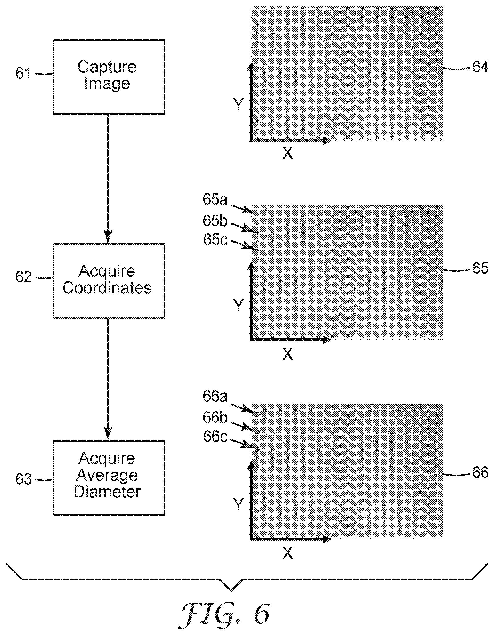
[0023] FIG. 3 shows an example of a pseudo random pattern of abrasive grains, wherein the pseudo random pattern is a pseudo-poisson pattern with a 14% abrasive grain coverage.
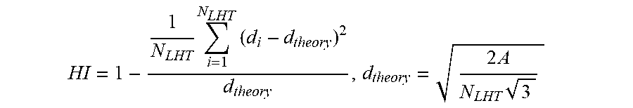
[0024] FIG. 4 shows an example of five circular active areas on an abrasive tool with a regular hexagonal pattern of abrasive grains.
[0025] FIG. 5 shows cutting direction for an abrasive tool.
[0026] FIG. 6 shows a flow chart illustrating how to convert an abrasive pattern into data that can be used for the Orientation Independence Test and the Local Homogeneity Test.
[0027] FIG. 7 shows the results of the Orientation Independence Test for abrasive grain pattern in FIG. 4.
[0028] FIG. 8 shows the output of the Local Homogeneity Test for the abrasive grain pattern in FIG. 4.
[0029] FIG. 9 shows the schematic for the regular hexagonal abrasive patterns used for Comparative Examples 1 and 2.
[0030] FIGS. 10a-10h show images of the patterns used for the Examples.
[0031] It is understood that the aspects of the invention may be utilized and structural changes may be made without departing from the scope of the invention. The figures are not necessarily to scale. Like numbers used in the figures refer to like components. However, it is understood that the use of a number to refer to a component in a given figure is not intended to limit the component in another figure labeled with the same number.
DETAILED DESCRIPTION
[0032] FIG. 1 shows a perspective view of example of an abrasive tool 10 with a regular hexagonal pattern of abrasive grains 12. Abrasive grains 12 comprise abrasive particles suspended in a resin and printed on a densified surface 16 of nonwoven web 14.
[0033] FIG. 2 shows an image of scratch patterns formed by the abrasive tool of FIG. 1. When the abrasive tool 20 is held at the orientation shown in FIG. 2, and the tool is moved in a lateral direction as shown by arrow 28, the cut patterns 22 created on a stainless steel surface. In general, a cutting surface or a work piece can be any surface less hardness than the abrasive features.
[0034] The cut patterns 22 on surface 21 are approximately evenly spaced apart and quite distinct and visible. In this scenario, the patterns are particularly visible because each of abrasive grains 23a, 23b, 23c, and so on are all cutting along the same line, thus resulting in a very noticeable cut or scratch pattern. When abrasive tool 24 is held at a slightly angled orientation, and the tool is moved in a lateral direction as indicated by arrow 28, the resulting cut or scratch lines 26 are more randomly spaced apart, but are still quite visible
[0035] Further, if a single abrasive grain was missed during the manufacturing process of abrasive tools 20 and 24, or if an extra abrasive grain was added to one of the pads, it would be visually apparent to even a casual observer. This results in a more challenging manufacturing quality standard and greater waste from the manufacturing process.
[0036] FIG. 3 shows an example of a pseudo random pattern of abrasive grains consistent with the present invention. A pseudo random pattern is an arrangement of abrasive grains that does not include a visually identifiable pattern to a human observer. However, in a pseudo-random pattern, the same seed in an algorithm that determines placement of the abrasive grains will result in the same distribution or placement of abrasive grains on an abrasive tool every time the algorithm is executed. While a pseudo-poisson arrangement of abrasive grains is used as an example in the present application, other specific pseudo-random abrasive arrangements will be apparent to one of skill in the art upon reading the present disclosure and are within the scope of the present invention.
[0037] Unlike a purely random pattern, a pseudo random pattern can provide the advantage of a relatively even distribution of abrasive grains on an abrasive tool without the manufacturing constraints created by a regular pattern of abrasive grains. Further, random patterns can have relatively large working surface areas without abrasive grain coverage, resulting in inferior performance in that particular area, while other areas may have a high concentration of abrasive grains, resulting in excessive or visual scratching resulting from use of that portion of the abrasive tool.
[0038] Unlike a regular pattern (as shown in FIG. 1), a pseudo random pattern can provide greater orientation independence, as defined according to the Orientation Independence Test, so that it can be used to abrade or scour at any orientation with comparable results. Additionally, relatively minor manufacturing defects in abrasive grain placement are visually apparent in the instance of a regular or patterned arrangement of abrasive grains. But a pseudo-random pattern consistent with the present application provides for more manufacturing flexibility.
[0039] In some instances, a pseudo-random pattern can comprise clusters of abrasives grains, where each cluster includes a plurality of abrasive grains arranged in a pseudo-random pattern, and where the clusters of abrasive grains form an array on a substrate in a regular or pseudo-random arrangement.
[0040] Generally, a cluster is a subsection of the hand-pad containing at least 3 features such that the percent of local area coverage of abrasive grains in the cluster is greater than the percent total area coverage of the abrasive grains in the hand pad.
[0041] As shown in FIG. 3, the pseudo random pattern is a pseudo-poisson pattern with a 14% abrasive grain coverage. A pseudo-poisson pattern is a variation on a traditional poisson distribution and is described in more detail in the Examples section. While 14% abrasive grain coverage is shown in FIG. 3, an abrasive tool consistent with the present disclosure may have a range of abrasive grain coverage, for example, abrasive grains may cover 10% to 30% of the working surface of an abrasive tool. Alternatively, an abrasive tool may have abrasive grain coverage in the range of 10% to 20% or 10% to 15%. While more abrasive grain coverage on a tool may lead to faster or more efficient cutting, other factors such as freer cutting to allow debris to fall away easily from the tool, cooler grinding or abrading, and manufacturing efficiency can result from lower abrasive grain coverage.
[0042] Abrasive tool 30 includes a substrate 32 and abrasive grains 33. In FIG. 3, the abrasive tool 30 is a hand pad that can be used for scouring or scrubbing; however, an abrasive tool consistent with the present disclosure can be any type of substrate with abrasive grains present. Examples of abrasive tools include tools for grinding, scouring, polishing, cutting, cleaning, finishing and sanding.
[0043] A substrate consistent with the present disclosure can include any substrate, such as paper, cloth, woven fabrics, nonwoven fabrics, calendared nonwoven fabrics, polymeric films, stitch-bonded fabrics, open cell foams, closed cell foams, vulcanized fiber materials, scrims, films, foils, screens, perforated sheets, other web-like substrates and combinations thereof. A substrate can include a single material with different types of treatments on different parts of the material. For example, a substrate made from a non-woven web may include a semi-densified layer as described by U.S. Patent Publication 2017/0051442 to Endle et al., incorporated herein by reference.
[0044] An abrasive grain may refer to single abrasive grits, engineered, structured or shaped cutting points, abrasive agglomerates, or abrasive particles, composites comprising a plurality of abrasive grits or composites thereof. Examples of abrasive grits include diamond, cubic boron nitride, boron, suboxide, various alumina grains, such as fused alumina, sintered alumina, seeded or unseeded sintered sol gel alumina, alumina zirconia grits, oxy-nitride alumina grits, silicon carbide, tungsten carbide, titanium carbide, garnet, iron oxide, tin oxide, feldspar, flint, emery, and modifications and combinations thereof. Such abrasive grits may exhibit a Mohs hardness in the range of 8-10 Mohs. Other materials that exhibit sufficient hardness to provide a scouring function may include, for example, particles of melamine-formaldehyde resin, phenolic resin, polymethl methacrylate, polystyrene, polycarbonate, certain polyesters and polyamides, and the like. Such materials may have a hardness in the range of at least 3 Mohs.
[0045] An abrasive grain may be any size consistent with the desired application for the abrasive tool. A composite having a plurality of abrasive grits in a resin may have a diameter in the range of 0.10 mm to 5 mm. Or may diameter in a range defined by any of 0.10 mm, 0.50 mm, 1 mm, 1.5 mm, 2 mm, 2.5 mm, 3 mm, 4 mm or 5 mm. A composite may have a height in the range of 0.05 mm to 2 mm. Or may have a height in a range defined by any of 0.10 mm, 0.25 mm, 0.50 mm, 0.75 mm, 1.0 mm, 1.5 mm or 2 mm.
[0046] Examples of shaped abrasive particles can be found in U.S. Pat. No. 5,201,916 (Berg); U.S. Pat. No. 5,366,523 (Rowenhorst RE 35,570); and U.S. Pat. No. 5,984,988 (Berg). U.S. Pat. No. 8,034,137 (Erickson et al.) describes alumina crushed abrasive particles that have been formed in a specific shape, then crushed to form shards that retain a portion of their original shape features. In some instances, shaped alpha alumina particles are precisely-shaped (i.e., the particles have shapes that are at least partially determined by the shapes of cavities in a production tool used to make them.)
[0047] Structured or shaped abrasive particles may be desirable for more efficient or higher precision grinding, polishing or abrading applications. In these types of tools, small shaped composite structures, such as three dimensional pyramids, diamonds, lines, and hexagonal ridges are replicated in a regular pattern on a surface of a tool.
[0048] Abrasive agglomerates can include single abrasive particles bonded together with, for example, a polymer, a ceramic, a metal or a glass to form an abrasive agglomerate.
[0049] Composites comprising a plurality of abrasive grits can include any type of abrasive grit discussed herein, or another type of abrasive grit that would be apparent to use to one skilled in the art upon reading the present disclosure. Abrasive grits can be combined with a range of resins, such as thermosetting resins, UV curable resins, solvent-based resins, including, in a non-limiting fashion, resins such as phenolic resins, aminoplast resins, curable acrylic resins, cyanate resins, urethanes, latex resins, nitrile resin, ethylene vinyl acetate resin, polyurethane resin, polyurea or urea-formaldehyde resin, isocyanate resin, styrene-butadiene resin, styrene-acrylic resin, vinyl acrylic resin, melamine resin, polyisoprene resin, epoxy resin, ethylenically unsaturated resin, and combinations thereof.
[0050] Abrasive grains may be aligned and placed on a substrate using an alignment tool as described in U.S. Patent Publication No. 2016/037250. In another instance, direct transfer of abrasive grains onto the substrate may be carried out by placing a droplet of bonding material on the substrate at the proper location and using a robotic arm to place each abrasive grain on the substrate. A robotic arm may also be used to place a suspended array of abrasive on a substrate that is pre-coated with a bonding material. In some instances, a bonding material may be a resin as discussed herein. In some instances, a bonding material may be an adhesive.
[0051] In some instances, abrasive grains (and particularly grits in resin) may be printed on an abrasive substrate using a screen printing or other printing method as will be apparent to one of skill in the art upon reading the present disclosure.
[0052] Abrasive grains may be bonded to a substrate using an adhesive make coat, or they may be affixed directly to a substrate. Adhesives or bonding materials used to secure an abrasive grain to a substrate will depend on the particular abrasive grain and substrate. Examples of bonding materials include adhesives, brazing materials, electroplating materials, electromagnetic materials, electrostatic materials, vitrified materials, metal powder bond materials, polymeric materials and resin materials and combinations thereof.
[0053] While the abrasive tool shown in FIG. 3 has a rectangular substrate and is designed for lateral movement, an abrasive tool may be a variety of geometric shapes and may be designed for rotation instead of lateral movement. For example, an abrasive tool may have a shape such as a rectangle, disk, rim, ring, cylinder, belt, conical, irregular shapes (such as in dental drills) or any combination of these shapes.
[0054] Variations on the present invention will be apparent to one of skill in the art upon reading the present disclosure, and are within the scope of the invention set forth herein.
Examples
[0055] Example patterns for abrasive hand-pad articles were generated. The scratch patterns on a simulated surface were analyzed. And the results are shown below.
[0056] Test Methods
[0057] Orientation Independence Test (OIT)
[0058] OIT Test Overview
[0059] The OIT analyzed the number of unique scratches made by Active Areas (AAs) chosen on a hand-pad (a type of abrasive tool). The active areas were defined as sections of the hand-pad encompassing a subset of the features used to abrade a substrate. The analysis consisted of randomly chosen (AAs) on the hand-pad surface that were of equal size and encompassed 10 to 50 abrasive features or abrasive grains. FIG. 4 shows an example of five circular AAs 41, 42, 43, 44, 45 chosen on a hand-pad 40 with a hexagonally close-packed (Hex) abrasive pattern.
[0060] To conduct the OIT, linear scratches made or simulated with the chosen AAs 41, 42, 43, 44, 45 covering cutting directions ranging from 0 to 90 degrees in one degree increments, where 0 degree cutting direction is defined to be in the X direction were evaluated. FIG. 5 illustrates cutting direction. Axis 51 shows the alignment of the abrasive grains with X and Y coordinates. Diagram 52 shows a cut direction at a 0 degree angle. Diagram 53 shows a cut direction at a 90 degree angle.
[0061] The OIT linear scratch test can be simulated or performed on a physical abrasive tool. The simulated test assumes that both the 2D coordinates of the centers of the abrasive features, and the average feature diameter on the hand-pad are known. Also note that the simulated test can be performed from a physical hand-pad or other type of abrasive tool providing these inputs are made available. For a step-by-step procedure on how the inputs can be obtained from a physical hand-pad, refer to the section titled `OIT Test Input` below.
[0062] OIT Test Input
[0063] For the simulated OIT test described, the tests take as input: 1) the 2D coordinate of the centers of the abrasive features, and 2) the average diameter of the envelope that surrounds each abrasive feature. The method to obtain these two inputs for a physical hand pad or other abrasive tool can be done through image analysis and is illustrated in the steps shown in FIG. 6 and described below:
[0064] Step 1: Image Capture 61 of Abrasive Tool
[0065] Place abrasive tool onto a flat surface so that the abrasive grains (or abrasive features) are clearly visible. Arrange a camera so that the lens points in the direction approximately perpendicular to the hand-pad. Place the camera sufficiently far to capture the entire surface of the abrasive tool in the camera's field of view and capture the image. Abrasive tool 64 in FIG. 6 is an example of an image capture of a hand-pad with a hexagonal abrasive grain pattern. Also shown in image 64 is the definition of the XY plane (that is, the XY plane is defined as the plane spanned by the flat abrasive tool surface). For abrasive tools that are not flat, a rectangular representative surface area of the abrasive tool can be extracted, flattened, and used for the following analysis.
[0066] Step 2: Acquire Coordinates 62 of Abrasive Grain Centers
[0067] Define one corner of the hand-pad as (0, 0) and generate list of the coordinates of the centers of the abrasive features. Image 65 in FIG. 6 shows an example of acquiring the coordinates of three abrasive grains 65a (coordinates (84, 2.5)), 65b (coordinates (72, 2.5)), and 65c (coordinates (60, 2.5)) on the hand-pad.
[0068] Step 3: Acquire Average Diameter 63 of the Abrasive Grains
[0069] Define the average diameter of the abrasive grains or abrasive features as:
D Ave = 1 N pad i = 1 N pad D i ##EQU00001##
[0070] where D.sub.i is the diameter of each abrasive grain. When an abrasive grain is non-circular, D.sub.i is measured as the diameter of the smallest circle that can fit around the abrasive grain. N.sub.pad is the number of grains on the abrasive pad or in the sampled section. Image 66 in FIG. 6 shows an example of acquiring the abrasive grain diameter three of the abrasive grains 66a, 66b, 66c on the abrasive tool. Each of the abrasive grains 66a, 66b, 66c had a diameter of 2.5 mm as shown in Image 66.
[0071] Performing the OIT Test
[0072] The OIT method uses a scratch profile made by N.sub.OIT cutting points for analysis. N.sub.OIT should be in the range of 10 to 50 cutting points. N.sub.OIT represents the number of abrasive grains in an AA.
[0073] For each cutting direction the number of unique scratches found on the abraded substrate were counted. Multiple cutting points may result in scratches that are very close or even overlapping. Scratches that were closer to each other than 10% of the average abrasive grain diameter (D.sub.AVE) were counted as a single scratch. The analysis was repeated for the 90 cutting directions considered and normalize by the maximum number of unique scratches found. The OIT score is the difference between the maximum and minimum number of unique scratches found in the 90 cutting directions considered. The pass/fail criteria is defined to be patterns that exhibit OIT scores of less than 0.20 (i.e., OIT<0.20=pass). FIG. 7 shows an example of the output 70 of a simulated OIT for the abrasive tool shown in FIG. 4. Points 73, 74 and 75 are all areas where multiple abrasive features scratched along the same line. Orientation Independence is measured by the difference between the highest and lowest point on the output 70. Difference 72 is approximately 0.20 for the abrasive tool shown in FIG. 4, and thus not a passing score on the OIT.
[0074] Local Homogeneity Test (LHT)
[0075] The LHT evaluates the homogeneity of the entire abrasive tool by calculating the Homogeneity Index (HI) each of multiple sections located on the abrasive tool. Each section considered was chosen such N.sub.LHT of the nearest abrasive grains were included, and N.sub.LHT was in the range of 40 to 70. When performing the LHT on the abrasive tool shown in FIG. 4, the abrasive tool was divided up into sections that were evenly spaced 1 mm apart. Each section comprised a region containing 50 of the nearest abrasive grains. Each section was analyzed according to equation below. The LHT analyzes each section and creates a heat map based on the HI score of each section. The HI score for a section on the abrasive tool is given by:
HI = 1 - 1 N LHT i = 1 N LHT ( d i - d theory ) 2 d theory , d theory = 2 A N LHT 3 ##EQU00002##
[0076] Where:
[0077] N.sub.LHT is the number of features in the bounding box;
[0078] A is the area of the bounding section; and
[0079] d.sub.i is the nearest neighbor distance of the i-th feature in the bounding section.
[0080] The resulting HI is associated with the abrasive grain at the center of a given section
[0081] The pass criteria for the LHT is defined as all sections on an abrasive tool having an HI score between 0.7 and 0.9 (i.e., (0.7<HI<0.90)=pass).
[0082] FIG. 8 shows a heat map of the output of a LHT for the abrasive grain pattern shown in FIG. 5. In the heat map shown in FIG. 8, the LHI score is: (min, max)=(0.9395, 0.9956) (a failing score).
[0083] Empirical observations of LHT results of several abrasive tool examples indicated that abrasive tools with regions having HI<0.70 was found to exhibit poor average feature spacing control. On the other hand, regions with HI>0.90 are regions of high symmetry which would manifest itself in poor OIT performance implying sensitivity of the hand-pad to varying cutting directions. Passing both tests (OIT and LHT) according to the passing criteria described herein ensures that the patterns exhibit 1) consistent feature to feature spacing across the hand-pad, and 2) an insensitivity to cutting direction, regardless of which section of the abrasive tool is used.
[0084] Simulated Abrasive Grain Examples
[0085] A total of eight different simulated abrasive grain arrangements were tested under the OIT and the LHT. The eight abrasive grain arrangements included four different "patterns", with each pattern being tested at two different levels of abrasive grain coverage, 14% and 26%, respectively.
[0086] Hex Pattern:
[0087] Two of the patterns were abrasive grains arranged in a regular hex pattern. The 14% coverage hex pattern is shown in FIG. 10a (referred to as Comparative Example 1 or CE 1), and the 26% coverage hex pattern is shown in FIG. 10b (referred to as Comparative Example 2 or CE 2). FIG. 9 shows the basic arrangement of abrasive grains use to create the hex pattern in FIGS. 10a and 10b. The hex pattern shown in FIG. 9 was two interpenetrating rectangular grids where the second grid was offset by c and d in the horizontal and vertical directions respectively. Distances a, b, c, and d as labeled in FIG. 9 are shown in the table below for CE1 and CE2.
TABLE-US-00001 TABLE 1 Quantities to generate the hex comparative example patterns Hex at 14% (CE1) Hex at 26% (CE2) a 11.0 mm 8.5 mm b 6.5 mm 4.5 mm c 5.5 mm 4.25 mm d 3.25 mm 2.25 mm
[0088] Vogel Pattern:
[0089] Two of the patterns were abrasive grains arranged in a Vogel pattern. The 14% coverage Vogel pattern is shown in FIG. 10c (referred to as Comparative Example 3 or CE 3), and the 26% coverage Vogel pattern is shown in FIG. 10d (referred to as Comparative Example 4 or CE 4). The Vogel pattern was defined by the following equation:
r=c {square root over (n)},.theta.=ng
[0090] Where n represents a positive integer and indexes the number of abrasive grains generated, c represents a positive real number, and g represents an irrational number approximately equal to 2.39996 radians (an approximation of the golden angle). In the present work, c=1 mm and so the (x,y) coordinate of the n-th feature in the pattern was given by:
(X,Y).sub.n= {square root over (n)}(cos(ng), sin(ng))
[0091] Pseudo-Random Pattern:
[0092] Two of the patterns were abrasive grains arranged in a Pseudo-Random (Pseudo-Poisson). The 14% coverage pseudo-random pattern is shown in FIG. 10e (referred to as Example 1 or E1). The 26% coverage pseudo-random pattern is shown in FIG. 10f (referred to as Example 2 or E2). The pseudo code below explains how the locations for each point in the pseudo-random pattern of Example 1 and Example 2 were generated.
TABLE-US-00002 CODE FOR PSEUDO-POISSON PATTERN GENERATION Inputs: PadX; Width of abrasive pad PadY; Height of abrasive pad x.sub.0; Initial position of 1.sup.st dot. Bold quantities denote 2D vectors. R.sub.ave; Average radius of dots Coverage; Area coverage of dots .alpha.; User-prescribed to control spacing variance (.DELTA.x, .DELTA.y); Vector of maximum allowable deviation from minimum. Prescribed to control randomness Start of pseudo-code PadArea = PadX * PadY; area of rectangular abrasive pad DotArea = 3.14159 * Rave{circumflex over ( )}2; area of each dot N.sub.pts = Floor[(Coverage * Pad Area)/(DotArea)]; Number of points for desired coverage X.sub.0 = x.sub.0; 1st point (taken as input) d = Sqrt[ PadX{circumflex over ( )}2 + PadY{circumflex over ( )}2]; distance from periodic images of 1.sup.st point Energy = .alpha. / d{circumflex over ( )}2 Energy increase due to insertion of 1.sup.st point For i=1 to N.sub.pts Loop to fill abrasive pad area with points X = Minimize[Energy + alpha / (X.sub.i-1 - X) Find X that minimizes energy. (X.sub.i-1 - X)]; Minimize[ ] is a standard technique in numerical methods. The function here searches for X in the abrasive pad that minimizes the value in the parenthesis [Energy0 + alpha / (X.sub.i-1 - X) (X.sub.i-1 - X). `` denotes dot product between two vectors Xi = X + [Rand([-1, 1]) * .DELTA.x; Perturbed position to insert Rand[-1, 1]) * .DELTA.y]; randomness. Rand[(-1, 1)] returns random number between -1 to 1. Energy = Energy + alpha / (X.sub.i-1 - X.sub.i) (X.sub.i-1 - X.sub.i); endfor end of pseudo-code Outputs: X.sub.0, X.sub.1, .... , X.sub.Npts Positions of all the points in the pattern
[0093] Random Pattern:
[0094] Two of the patterns were abrasive grains arranged in a random manner. The 14% coverage random pattern is shown in FIG. 10g (referred to as Comparative Example 5 or CE5). The 26% coverage random pattern is shown in FIG. 10h (referred to as Comparative Example 5 or CE5). The random arrangement of particles was generated using Mathematica version 10.3 (a commercial mathematical analysis tool available form Wolfram, Champaign, Ill.) random number generator, a random hand-pad pattern was generated by prescribing the minimum distance between each feature, and generating enough points so as to cover the entire hand-pad at the prescribed coverage.
[0095] In each of the Examples/Comparative Examples, the feature diameters are all 2.5 mm, and the XY coordinates are can be derived as described herein. The OIT and LHT described above were performed on each of the Examples/Comparative Examples described. The results from these tests are summarized in Table 2.
Results
TABLE-US-00003 [0096] TABLE 2 Results from the OIT and LHT of the 8 different abrasive feature patterns % Area LHI: Cover- OIT OIT: LHI LHI Pass/ Example age Score Pass/Fail Min Max Fail E1 14 0.0571 Pass 0.7528 0.8801 Pass E2 26 0.0554 Pass 0.7410 0.8780 Pass CE1 14 0.2000 Fail 0.9395 0.9956 Fail CE2 26 0.1510 Pass 0.8751 0.9673 Fail CE3 14 0.0667 Pass 0.7799 0.9166 Fail CE4 26 0.0585 Pass 0.7722 0.9398 Fail CE5 14 0.0476 Pass 0.5461 0.7039 Fail CE6 26 0.0037 Pass 0.6419 0.7891 Fail
[0097] Of the various patterns tested, only E1 and E2 exhibited passing scores for both the Orientation Independent Test and the Local Homogeneity Test.
* * * * *
D00000
D00001
D00002
D00003
D00004
D00005
D00006
D00007
D00008
XML
uspto.report is an independent third-party trademark research tool that is not affiliated, endorsed, or sponsored by the United States Patent and Trademark Office (USPTO) or any other governmental organization. The information provided by uspto.report is based on publicly available data at the time of writing and is intended for informational purposes only.
While we strive to provide accurate and up-to-date information, we do not guarantee the accuracy, completeness, reliability, or suitability of the information displayed on this site. The use of this site is at your own risk. Any reliance you place on such information is therefore strictly at your own risk.
All official trademark data, including owner information, should be verified by visiting the official USPTO website at www.uspto.gov. This site is not intended to replace professional legal advice and should not be used as a substitute for consulting with a legal professional who is knowledgeable about trademark law.