Thermal-assisted Multiple Sheet Roll Forming
Sachdev; Anil K. ; et al.
U.S. patent application number 16/196015 was filed with the patent office on 2020-05-21 for thermal-assisted multiple sheet roll forming. The applicant listed for this patent is GM GLOBAL TECHNOLOGY OPERATIONS LLC. Invention is credited to John E. Carsley, Anil K. Sachdev, Robert N. Saje.
| Application Number | 20200156134 16/196015 |
| Document ID | / |
| Family ID | 70470670 |
| Filed Date | 2020-05-21 |


| United States Patent Application | 20200156134 |
| Kind Code | A1 |
| Sachdev; Anil K. ; et al. | May 21, 2020 |
THERMAL-ASSISTED MULTIPLE SHEET ROLL FORMING
Abstract
A thermal-assisted method deforms a sheet metal assembly having constrained ends. A focus bending area located between the constrained ends is heated. The focus bending area is bent while the sheet metal assembly is within an elevated bending temperature range. A sheet metal assembly may be formed by this method, which includes an outer metal sheet and an inner metal sheet fixed together to form constrained ends. The sheet metal assembly has a bend formed therein between the first and second constrained ends, wherein each metal sheet is bent at the bend with a maximum gap between the inner and outer metal sheets at the bend. The maximum gap is no greater than five times the thickness of one of the inner and outer metal sheets, and the bend has a radius less than three times the thickness of one of the inner and outer sheets.
| Inventors: | Sachdev; Anil K.; (Rochester Hills, MI) ; Carsley; John E.; (Oakland, MI) ; Saje; Robert N.; (Shelby Township, MI) | ||||||||||
| Applicant: |
|
||||||||||
|---|---|---|---|---|---|---|---|---|---|---|---|
| Family ID: | 70470670 | ||||||||||
| Appl. No.: | 16/196015 | ||||||||||
| Filed: | November 20, 2018 |
| Current U.S. Class: | 1/1 |
| Current CPC Class: | B32B 15/012 20130101; B21D 5/008 20130101; C21D 1/667 20130101; B21D 35/005 20130101; B21D 5/08 20130101; B21D 35/007 20130101; B32B 15/011 20130101; C21D 1/34 20130101; C21D 2251/02 20130101; B21D 37/16 20130101; C21D 2221/00 20130101 |
| International Class: | B21D 5/08 20060101 B21D005/08; C21D 1/667 20060101 C21D001/667 |
Claims
1. A method of forming a sheet metal assembly, the method comprising: providing a sheet metal assembly, the sheet metal assembly including at least an outer metal sheet and an inner metal sheet, the outer and inner metal sheets being fixed together to form a constrained first end and a constrained second end, the sheet metal assembly having an initial temperature; heating a focus bending area of the sheet metal assembly to at least a bending temperature range that is greater than the initial temperature, the focus bending area being located between the constrained first and second ends of the sheet metal assembly; and bending the focus bending area of the sheet metal assembly while the sheet metal assembly is within the bending temperature range.
2. The method of claim 1, wherein the step of bending includes rolling a roller tool against the sheet metal assembly to form a bend in the focus bending area, the bend having an outer side and an inner side.
3. The method of claim 2, further comprising disposing a heat source adjacent to the outer sheet at the focus bending area prior to performing the heating step, and heating the focus bending area via the heat source.
4. The method of claim 1, wherein the step of heating includes applying a laser beam to the focus bending area.
5. The method of claim 1, further comprising: providing the inner metal sheet as being formed of a first material; and providing the outer metal sheet as being formed of a second material, the first and second materials being different from one another.
6. The method of claim 1, further comprising: providing one of the inner and outer metal sheets as being formed of an aluminum alloy; and providing the other of the inner and outer metal sheets as being formed of steel.
7. The method of claim 1, further comprising: providing the inner metal sheet having a first thickness; and providing the outer metal sheet having a second thickness, the first and second thicknesses being unequal.
8. The method of claim 1, wherein the step of bending comprises forming a bend at the focus bending area, the method further comprising maintaining a maximum gap between the inner and outer metal sheets at the bend, the maximum gap being no greater than five times the thickness of one of the inner and outer metal sheets.
9. The method of claim 8, wherein the maximum gap is no greater than half the thickness of one of the inner and outer metal sheets.
10. The method of claim 1, further comprising quenching the sheet metal assembly rapidly after bending to retain a high-temperature phase structure at room temperature.
11. The method of claim 1, wherein the step of bending comprises forming a bend at the focus bending area, the bend having a radius less than three times the thickness of one of the inner and outer metal sheets.
12. The method of claim 1, further comprising providing the inner and outer metal sheets having substantially equal thicknesses.
13. The method of claim 2, further comprising providing a die having a die bend formed therein, wherein the step of bending includes rolling the sheet metal assembly against the die bend with the roller tool to form a part bend in the sheet metal assembly.
14. A sheet metal assembly comprising: an outer metal sheet; and an inner metal sheet, the outer and inner metal sheets being fixed together to form a constrained first end and a constrained second end, the sheet metal assembly having a bend formed therein between the first and second constrained ends, wherein each metal sheet is bent at the bend with a maximum gap between the inner and outer metal sheets at the bend, the maximum gap being no greater than five times the thickness of one of the inner and outer metal sheets, the bend having a radius less than three times the thickness of one of the inner and outer metal sheets.
15. The sheet metal assembly of claim 14, the inner metal sheet being formed of a first material, and the outer metal sheet being formed of a second material, the first and second materials being different from one another.
16. The sheet metal assembly of claim 15, one of the inner and outer metal sheets being formed of an aluminum alloy, and the other of the inner and outer metal sheets being formed of steel.
17. The sheet metal assembly of claim 14, the inner metal sheet having a first thickness, and the outer metal sheet having a second thickness, the first and second thicknesses being unequal.
18. The sheet metal assembly of claim 14, wherein the maximum gap is no greater than half the thickness of one of the inner and outer metal sheets.
19. The sheet metal assembly of claim 14, at least one of the inner and outer metal sheets retaining a high-temperature phase structure at room temperature.
20. The sheet metal assembly of claim 14, the inner and outer metal sheets having substantially equal thicknesses.
Description
FIELD
[0001] The present technology relates generally to metal forming and, more specifically, the present technology relates to a heat-assisted metal forming process for a constrained sheet metal assembly.
INTRODUCTION
[0002] Roll forming at a production facility is normally done at room temperature using a series of progressively different rollers to bend and plastically deform a single sheet of material into a desired form. The process is continuous and at high speed, and the result is a sheet material bent into a particular profile for a particular purpose.
[0003] Future products are, however, being designed with higher strength materials, while sophisticated computer analysis is driving profile designs with increasingly greater complexity often demanding sharp corners that are also high-strength. These two factors work counter to each other and regions subjected to the large strains fracture when bending high-strength materials.
[0004] To add difficulty, when two sheets are welded at their edges, the entire sheet metal assembly needs to move as one unit. If the two metal sheets, which may not have a neutral axis at their mating surfaces, are attempted to be bent, the metal sheets attempt to separate at the bend due to compressive stresses on the inner side of the neutral axis and tensile stresses on the outer side of the neutral axis. The result is that the inner sheet will be pushed inward and the sheets will not stay together at the bend.
SUMMARY
[0005] The present disclosure provides a system and method that enables deformation of a sheet metal assembly having attached constrained ends around a tight bend without the sheet metal separating at the bend, as well as a sheet metal assembly that has a sharp bend with sheet metal pieces that substantially stay together at the bend.
[0006] In one form, which may be combined with or separate from the other forms disclosed herein, a method of forming a sheet metal assembly is provided. The method includes providing a sheet metal assembly, the sheet metal assembly including at least an outer metal sheet and an inner metal sheet, where the outer and inner metal sheets are fixed together to form a constrained first end and a constrained second end. The sheet metal assembly has an initial temperature. The method also includes heating a focus bending area of the sheet metal assembly to at least a bending temperature range that is greater than the initial temperature. The focus bending area is located between the constrained first and second ends of the sheet metal assembly. Additionally, the method includes bending the focus bending area of the sheet metal assembly while the sheet metal assembly is within the bending temperature range.
[0007] In another form, which may be combined with or separate from the other forms disclosed herein, a sheet metal assembly is provided that includes an outer metal sheet and an inner metal sheet. The outer and inner metal sheets are fixed together to form a constrained first end and a constrained second end. The sheet metal assembly has a bend formed therein between the first and second constrained ends. Each metal sheet is bent at the bend with a maximum gap between the inner and outer metal sheets at the bend. The maximum gap is no greater than five times the thickness of one of the inner and outer metal sheets. The bend has a radius less than three times the thickness of one of the inner and outer metal sheets.
[0008] Additional features may be provided, including but not limited to the following: wherein the step of bending includes rolling a roller tool against the sheet metal assembly to form a bend in the focus bending area, the bend having an outer side and an inner side; disposing a heat source adjacent to the outer sheet and/or the inner sheet at the focus bending area prior to performing the heating step; heating the focus bending area via the heat source; wherein the step of heating includes applying a laser to the focus bending area; providing the inner metal sheet as being formed of a first material; providing the outer metal sheet as being formed of a second material; the first and second materials being different from one another or the same; providing at least one of the inner and outer metal sheets as being formed of an aluminum alloy; providing at least one of the inner and outer metal sheets as being formed of steel; providing the inner metal sheet having a first thickness; providing the outer metal sheet having a second thickness; the first and second thicknesses being unequal; the first and second thicknesses being substantially equal to one another; maintaining a maximum gap between the inner and outer metal sheets at the focus bending area; the maximum gap being no greater than five times the thickness of one of the inner and outer metal sheets; the maximum gap being no greater than half the thickness of one of the inner and outer metal sheets; quenching the sheet metal assembly rapidly after bending to retain a high-temperature phase structure at room temperature or to obtain a different phase structure based on a controlled cooling rate based on equilibrium phase transformations; wherein bending the sheet metal assembly further comprises forming the bend to a radius less than three times the thickness of one of the inner and outer metal sheets; providing a die or an opposing roller tool having a bend formed therein; wherein the step of bending the sheet metal assembly includes rolling the sheet metal assembly against the die bend with the roller tool to form a part bend in the sheet metal assembly; and/or at least one of the inner and outer metal sheets retaining a high-temperature phase structure at room temperature.
[0009] Further features and advantages of the technology, as well as the structure and operation of various examples of the technology, are described in detail below with reference to the accompanying drawings. It is noted that the technology is not limited to the specific examples described herein. Such examples are presented herein for illustrative purposes only. Additional examples will be apparent to persons skilled in the relevant art(s) based on the teachings contained herein.
BRIEF DESCRIPTION OF THE DRAWINGS
[0010] The drawings described herein are for illustration purposes only and are not intended to limit the scope of the present disclosure in any way.
[0011] FIG. 1 is a schematic cross-sectional view showing an unbent sheet metal assembly in a first step of a method of forming the sheet metal assembly, according to the principles of the present disclosure;
[0012] FIG. 2 is a schematic cross-sectional view of the unbent sheet metal assembly of FIG. 1 with accompanying tools for forming the sheet metal assembly, in accordance with the principles of the present disclosure;
[0013] FIG. 3 is a schematic cross-sectional view of the sheet metal assembly of FIGS. 1 and 2 in a partially bent configuration, in accordance with the principles of the present disclosure;
[0014] FIG. 4 is a schematic cross-sectional view of the sheet metal assembly of FIGS. 1-3 having a bend formed therein, in accordance with the principles of the present disclosure;
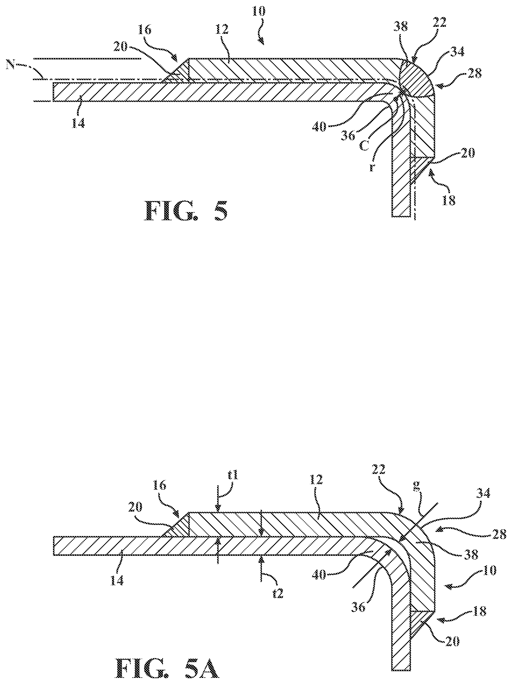
[0015] FIG. 5 is a schematic cross-sectional view of a bent sheet metal assembly after performing steps as illustrated in FIGS. 1-4, in accordance with the principles of the present disclosure; and
[0016] FIG. 5A is a schematic cross-sectional view of another variation of the bent sheet metal assembly after performing steps as illustrated in FIGS. 1-4, in accordance with the principles of the present disclosure.
DETAILED DESCRIPTION
[0017] While the present technology is described herein with illustrative examples for particular applications, it should be understood that the technology is not limited thereto. Those skilled in the art with access to the teachings provided herein will recognize additional modifications, applications, and examples within the scope thereof and additional fields in which the technology would be of significant utility.
[0018] The present disclosure discloses a thermal-assisted method for plastically deforming a sheet metal assembly. Thus, the method relates to forming a sheet metal assembly having a bend therein.
[0019] A sheet metal assembly 10 is provided that includes at least an "outer" metal sheet 12 and an "inner" metal sheet 14. The metal sheet 12 is referred to as an "outer sheet," and the metal sheet 14 is referred to as an "inner sheet," because the metal sheet 12 will be located on an outer side of a bend and the metal sheet 14 will be located on an inner side of a bend, which will be described below. Additional metal sheets may also be included in the sheet metal assembly 10, if desired. Therefore, the sheet metal assembly 10 could have two, three, four, five, or any desired number of metal sheets.
[0020] The outer and inner metal sheets 12, 14 are fixed together to form a constrained first end 16 and a constrained second end 18. For example, the outer and inner metal sheets 12, 14 may be fixed together by welding, brazing, rivets, or in any other desired manner. In the illustrated example, weld joints 20 attach the outer and inner metal sheets 12, 14 together at the first and second constrained ends 16, 18.
[0021] The sheet metal assembly 10 has a certain temperature, referred to as the initial temperature, prior to bending. The initial temperature may be room temperature, by way of example.
[0022] Each metal sheet 12, 14 may be formed of the same or dissimilar materials. For example, both metal sheets 12, 14 could be formed of steel, or one of the metal sheets 12, 14 could be formed of steel and the other 12, 14 of aluminum or an aluminum alloy. Each metal sheet 12, 14 may be either coated or uncoated.
[0023] If alloyed, the aluminum alloy may include at least 85 wt % aluminum. Some notable aluminum alloys that may constitute the coated or uncoated aluminum substrate are an aluminum-magnesium alloy, an aluminum-silicon alloy, an aluminum-magnesium-silicon alloy, and an aluminum-zinc alloy. If coated, the aluminum metal sheet may include a surface layer of a refractory oxide material (native and/or produced during manufacture when exposed to high-temperatures, e.g., mill scale) comprised of aluminum oxide compounds and possibly other oxide compounds such as, for example, those of magnesium oxide if the aluminum substrate contains magnesium. The aluminum metal sheet may also be coated with a layer of zinc, tin, or a metal oxide conversion coating comprised of oxides of titanium, zirconium, chromium, or silicon, such as described in U.S. Pat. No. 9,987,705. The aluminum metal sheet may be provided in wrought or cast or extruded forms. For example, the metal sheet may be composed of a 2xxx, 3xxx, 4xxx, 5xxx, 6xxx, or 7xxx series wrought aluminum alloy sheet layer, extrusion, forging, or other worked article. Alternatively, the metal sheet may be composed of a 4xx.x, 5xx.x, 6xx.x, or 7xx.x series aluminum alloy casting. Other aluminum alloys that may be used include, but are not limited to, AA5754 and AA5182 aluminum-magnesium alloy, AA6111 and AA6022 aluminum-magnesium-silicon alloy, AA7003 and AA7055 aluminum-zinc alloy, and Al-10Si-Mg aluminum die casting alloy. An aluminum metal sheet may further be employed in a variety of tempers including annealed (O), strain hardened (H), an unstable condition (W), and solution heat treated (T), if desired. When more than one aluminum metal sheet is used in the sheet metal assembly 10, the aluminum metal sheets may be the same or different in terms of their compositions, thicknesses, and/or form (e.g., wrought or cast).
[0024] One or both metal sheets 12, 14 may be formed of a steel having any of a wide variety of strengths and grades that is either coated or uncoated. The steel sheet may be hot-rolled or cold-rolled and may be composed of steel such as mild steel, interstitial-free steel, bake-hardenable steel, high-strength low-alloy (HSLA) steel, dual-phase (DP) steel, complex-phase (CP) steel, martensitic (MART) steel, transformation induced plasticity (TRIP) steel, quenched and partitioned steel (Q&P), twining induced plasticity (TWIP) steel, and boron steel such as when the steel sheet includes press-hardened steel (PHS). If coated, the steel sheet may include a surface layer of zinc (e.g., hot-dip galvanized or electrogalvanized), a zinc-iron alloy (e.g., galvannealed or electrodeposited), a zinc-nickel alloy, nickel, aluminum, an aluminum-magnesium alloy, an aluminum-zinc alloy, or an aluminum-silicon alloy.
[0025] Either of the metal sheets 12, 14 (and additional sheets, if included) may be a cold rolled sheet metal, for example aluminum of strength greater than 300 megapascal (MPa), preferably greater than 500 MPa, or steel of strength greater than 1000 MPa, preferably greater than 1500 MPa.
[0026] The method disclosed herein is used to ultimately form the sheet metal assembly 10 into an assembly having a bend in it. Each of the metal sheets 12, 14 may have unequal thicknesses t1, t2, respectively, or the thicknesses t1, t2 may be substantially equal to one another. The thicknesses t1, t2 may be in the range of 0.2-4.0 mm, by way of example. In cases where t1 and t2 are unequal, a neutral axis N is not located at the interface between one of the metal sheets 12, 14, but rather, the neutral axis N runs through one of the metal sheets 12, 14 (in this case, sheet 12). Accordingly, the entire inner sheet 14 will be in compression when the sheet metal assembly 10 is bent, and the outer sheet 12 will have portions 13 that are in compression and portions 15 that are in tension when the sheet metal assembly 10 is bent.
[0027] To ultimately form the sheet metal assembly 10 into an assembly having a bend in it, the method includes heating a focus bending area 22 of the sheet metal assembly 10 to at least a bending temperature range that is greater than the initial temperature. The focus bending area 22 may be heated, for example, by a heat source 24 disposed adjacent to the outer metal sheet 12 so that the outer metal sheet 12 at the focus bending area 22 becomes ductile and can stretch around a bend. The heat source 24 is disposed adjacent to the outer sheet 12 at the focus bending area 22 prior to performing the heating step. The focus bending area 22 is located between the constrained first and second ends 16, 18 of the sheet metal assembly 10. In the alternative, the heat source 24 could be disposed adjacent to the inner sheet 14 at the focus bending area 22 so that the heat is applied from the inside of the resulting bend.
[0028] The heat source 24 may be a laser heat source, such as a laser scanning beam, by way of example. Accordingly, the step of heating the focus bending area 22 may be accomplished by applying a laser beam 25 to the focus bending area 22. Other examples of heating may be induction, flame, focused halogen, high intensity infra-red sources, conduction heating, or resistance heating, in which a current would pass from one roller tool in contact with one side of the sheet through the sheet thickness to a second roller in contact with the other side of the sheet. In resistance heating, the resistance of the material to the flow of electrical current is what causes the heating effect. The heating is then used to assist the bending of the sheet material. In conduction heating, one or more rollers may be heated by external sources (not shown), such that the material is heated by contact and bent as the material passes through these roller dies.
[0029] Once the focus bending area 22 reaches the bending temperature range, the focus bending area 22 of the sheet metal assembly 10 is bent to form a bend within the sheet metal assembly 10. The bending is accomplished while the sheet metal assembly 10 is within the bending temperature range. In some examples, the bending temperature range is within a two-phase sub-critical temperature region or above the critical temperature, but preferably above the critical temperature. Therefore, the actual bending temperature range depends on the material used for the metal sheets 12, 14. In some examples, the heat source 24, preferably laser, heats the sheet metal 12, 14 to a solutionizing or austenitizing temperature.
[0030] Referring now to FIGS. 2 and 3, in some examples, to accomplish the bending of the sheet metal assembly 10 in the bending temperature range, a roller tool 26 is rolled against the sheet metal assembly 10 to form a bend 28 in the focus bending area 22. The sheet metal assembly 10 may be rolled by the roller tool 26 against a die 30 having a die bend 32 formed therein. In such an example, the sheet metal assembly 10 is bent by rolling the sheet metal assembly 10 against the die bend 32 with the roller tool 26 to form the bend 28 in the sheet metal assembly 10. The heat source 24 preferably is disposed directly adjacent to the roller tool 26 so that the focus bending area 22 is maintained within the bending temperature range while the sheet metal assembly 10 is bent by the roller tool 26.
[0031] As a result, as shown in FIGS. 4 and 5, a sharp bend 28 is formed in the sheet metal assembly 10, which is formed in both the outer and inner metal sheets 12, 14. The bend 28 has an outer side 34 formed in the outer sheet 12 and an inner side 36 formed in the inner sheet 14. Thus, the bend 28 is comprised of both an outer bend 38 in the outer sheet 12 and an inner bend 40 in the inner sheet 14. The outer and inner bends 38, 40 fit snugly together to form the bend 28 in the sheet metal assembly 10. In some examples, the outer and inner bends 38, 40 have no gap between them and contact each other, as shown in FIG. 5. The heating of the focus bending area 22 reduces forces on the portion 15 of the outer sheet 12 that is subject to tensile forces and helps balance the forces in the inner and outer bends 40, 38.
[0032] Referring now to FIG. 5A, in other examples, there is a gap g between the outer and inner bends 38, 40; in other words, there is a gap g between the outer and inner metal sheets 12, 14 at the bend 28 of the sheet metal assembly 10. By way of example, the gap g may be, no greater than five times the thickness t2, t1 of one of the inner and outer metal sheets 14, 12. Thus, in this example, the outer sheet 12 is thicker than the inner sheet 14, so the gap g is no greater than fives times t1. In other examples, the gap g may be much smaller, such as no greater than one half of the thickness t1, t2 of one of the outer and inner sheets 12, 14, or zero as shown in FIG. 5.
[0033] Because of the high intensity heating according to the present technology, the sheet metal assembly 10 can be bent to a small radius that is one to three times the thickness of the assembly 10 or of one of the individual sheets 12, 14. Thus, the bend 28 may be a sharp bend having a radius of curvature r that is less than three times the thickness of t1, t2 of one of the outer and inner metal sheets 12, 14 or of the assembly 10 as a whole. Accordingly, in one example, if the outer sheet 12 is thicker than the inner sheet 14, then the bend 28 may have a radius of curvature r that is no greater than three times t1, where the radius of curvature r is measured from a center C of the curve of the bend 28 to a neutral axis N of the sheet metal assembly 10. In other examples, the radius r is no greater than the thickness t1, t2 of one of the outer and inner sheets 12, 14, or no greater than twice the thickness t1, t2 of one of the outer and inner sheets 12, 14.
[0034] Cold rolled sheet metal exhibits elasticity and tends to spring back after bending, resulting in a radius of curvature that is greater than an initial bending radius. The use of intense laser heating with the present technology can essentially eliminate or greatly reduce the springback action of the sheet material, since springback is related to strength and the strength during bending at an elevated temperature is greatly reduced. The result is that the radius of curvature r is substantially similar to what is provided by the tooling system 26, 30 without the need for any post processing. Thus, the resulting radius r with the present technology can be smaller, such as between one to three times the thickness t1, t2, or t1+t2.
[0035] Although a single roller 26 is illustrated as rolling the sheet metal assembly 10 against the die 30, it should be understood that any other bending process, such as that using a plurality of rollers may be used to accomplish the bending when the sheet metal assembly 10 is in the bending temperature range. For example, the sheet metal assembly 10 may be continuously fed through parallel rollers on a roll-forming production line. In some examples, the sheet metal assembly 10 may be bent into the desired shape through several bending steps, with each bending step being performed with multiple roller dies. Additional heat sources may be used to heat the sheet metal assembly 10 prior to each rolling step, where the additional heat sources could be placed just before each set of rollers.
[0036] After forming the bend 28 in the sheet metal assembly 10, the method may include a rapid quenching. The rapid quenching can be done through a plurality of cold air jets, through a liquid spray (of water, oil, etc.), through quenching by contact (e.g., with roller tools), self-quench from the mass of the cold rolled sheet metal, gas jet, or a combination of these quenching methods. The rapid quenching avoids precipitation or any transformation in the sheet metal assembly 10. The rapid quench allows the alloys that demonstrate subsequent precipitation hardening, such as aluminum or magnesium, to retain the high-temperature phase structure at room temperature; the high-temperature phase will transform upon reaching room temperature to other higher strength phases, such as retained austenite, martensite, and/or bainite as in the case of steels. After the heating and quenching, the roll forming may continue with another set of roller dies, if desired.
[0037] The detailed description and the drawings or figures are supportive and descriptive of the many aspects of the present disclosure. The elements described herein may be combined or swapped between the various examples. While certain aspects have been described in detail, various alternative aspects exist for practicing the invention as defined in the appended claims. The present disclosure is exemplary only, and the invention is defined solely by the appended claims.
* * * * *
D00000
D00001
D00002
D00003
XML
uspto.report is an independent third-party trademark research tool that is not affiliated, endorsed, or sponsored by the United States Patent and Trademark Office (USPTO) or any other governmental organization. The information provided by uspto.report is based on publicly available data at the time of writing and is intended for informational purposes only.
While we strive to provide accurate and up-to-date information, we do not guarantee the accuracy, completeness, reliability, or suitability of the information displayed on this site. The use of this site is at your own risk. Any reliance you place on such information is therefore strictly at your own risk.
All official trademark data, including owner information, should be verified by visiting the official USPTO website at www.uspto.gov. This site is not intended to replace professional legal advice and should not be used as a substitute for consulting with a legal professional who is knowledgeable about trademark law.