Hydraulic Systems For Delivering Prosthetic Heart Valve Devices And Associated Methods
McLean; Matthew
U.S. patent application number 16/752137 was filed with the patent office on 2020-05-21 for hydraulic systems for delivering prosthetic heart valve devices and associated methods. The applicant listed for this patent is Twelve, Inc.. Invention is credited to Matthew McLean.
| Application Number | 20200155305 16/752137 |
| Document ID | / |
| Family ID | 62148474 |
| Filed Date | 2020-05-21 |


View All Diagrams
| United States Patent Application | 20200155305 |
| Kind Code | A1 |
| McLean; Matthew | May 21, 2020 |
HYDRAULIC SYSTEMS FOR DELIVERING PROSTHETIC HEART VALVE DEVICES AND ASSOCIATED METHODS
Abstract
Systems for delivering prosthetic heart valve devices and associated methods are disclosed herein. A delivery system configured in accordance with embodiments of the present technology can include, for example, an elongated catheter body, a delivery capsule carried by the elongated catheter body, and two fluid chambers within the delivery capsule. The delivery capsule can be hydraulically driven between a containment configuration for holding the prosthetic heart valve device and a deployment configuration for at least partially deploying the prosthetic heart valve device. For example, the delivery capsule can be urged towards the deployment configuration when fluid is removed from the first chamber and fluid is delivered into the second chamber, whereas the delivery capsule can be urged towards the containment configuration to resheathe the prosthetic heart valve device when fluid is removed from the second chamber and delivered into the first chamber.
| Inventors: | McLean; Matthew; (San Francisco, CA) | ||||||||||
| Applicant: |
|
||||||||||
|---|---|---|---|---|---|---|---|---|---|---|---|
| Family ID: | 62148474 | ||||||||||
| Appl. No.: | 16/752137 | ||||||||||
| Filed: | January 24, 2020 |
Related U.S. Patent Documents
| Application Number | Filing Date | Patent Number | ||
|---|---|---|---|---|
| 15490008 | Apr 18, 2017 | 10575950 | ||
| 16752137 | ||||
| Current U.S. Class: | 1/1 |
| Current CPC Class: | A61F 2/2433 20130101; A61F 2/9517 20200501; A61F 2/243 20130101; A61F 2002/9665 20130101; A61F 2/2436 20130101; A61F 2002/9534 20130101 |
| International Class: | A61F 2/24 20060101 A61F002/24 |
Claims
1. A system for delivering a prosthetic heart valve device for implantation at a native heart valve of a patient, the system comprising: an elongated catheter body; a delivery capsule coupled to the elongated catheter body and configured to contain the prosthetic heart valve device, wherein: the delivery capsule is configured to be hydraulically driven between a containment configuration for holding the prosthetic heart valve device and a deployment configuration for deploying at least a portion of the prosthetic heart valve device, the delivery capsule includes a housing and a platform that define, at least in part, a deployment chamber; and an expandable member coupled to the elongated catheter body and distal to the delivery capsule, wherein the expandable member is configured to urge the delivery capsule towards the containment configuration and resheathe at least a portion of the prosthetic heart valve device when fluid is at least partially drained from the deployment chamber while fluid is delivered to the expandable member.
2. The system of claim 1, wherein the delivery capsule is configured to substantially prevent translation of the prosthetic heart valve device relative to the elongated catheter body while the prosthetic heart valve device is at least partially resheathed.
3. The system of claim 1, wherein the delivery capsule further comprises a containment chamber configured to contain the prosthetic heart valve device, and wherein the containment chamber is fluidically sealed from the deployment chamber via the platform.
4. The system of claim 1, wherein the expandable member is a balloon.
5. A method for delivering a prosthetic heart valve device to a native mitral valve of a heart of a human patient, the method comprising: positioning a delivery capsule of an elongated catheter body within the heart, the delivery capsule carrying the prosthetic heart valve device; delivering fluid to a first chamber within the delivery capsule to move the prosthetic heart valve device from a containment configuration within the delivery capsule to a deployment configuration, wherein the first chamber is proximal to the prosthetic heart valve device; while fluid is delivered to the first chamber, draining fluid from a second chamber within the delivery capsule, wherein the second chamber is proximal to the prosthetic heart valve device; and allowing the prosthetic heart valve device to radially expand to engage tissue of the native mitral valve when the delivery capsule moves from the containment configuration towards the deployment configuration.
6. The method of claim 5, further comprising: urging the delivery capsule toward the containment configuration to resheathe the prosthetic heart valve device after allowing the prosthetic heart valve device to at least partially radially expand, wherein urging the delivery capsule toward the containment configuration comprises: draining fluid from the first chamber; and while draining fluid from the first chamber, delivering fluid to the second chamber.
7. The method of claim 5, wherein: delivering fluid to the first chamber comprises delivering fluid from a manifold at a proximal portion of the elongated catheter body via a first fluid lumen; and draining fluid from the second chamber comprises removing fluid via a second fluid lumen to the manifold.
8. The method of claim 5, wherein delivering fluid to the first chamber and draining fluid from the second chamber at least substantially prevents translation of the prosethetic heart valve device relative to the elongated catheter body while the prosthetic heart valve device moves from the containment configuration to the deployment configuration.
9. The method of claim 5, further comprising restraining a distal portion of the prosthetic heart valve device as the prosthetic heart valve device moves between the containment and deployment configurations, wherein the distal portion of the prosthetic heart valve device comprises attachment elements that releasably couple to pockets at a distal end region of an engagement shaft that extends through the elongated catheter body.
10. The method of claim 9, further comprising moving the engagement shaft distally relative to the delivery capsule to release the restrained distal portion of the distal end region of the engagement shaft and fully expand the prosthetic heart valve device.
Description
[0001] This application is a divisional of U.S. patent application Ser. No. 15/490,008, filed Apr. 18, 2017, the entire content of which is incorporated by reference herein.
CROSS-REFERENCE TO RELATED APPLICATIONS
[0002] The present application incorporates the subject matter of (1) International Patent Application No. PCT/US2014/029549, filed Mar. 14, 2014, (2) International Patent Application No. PCT/US2012/061219, filed Oct. 19, 2012, (3) International Patent Application No. PCT/US2012/061215, filed Oct. 19, 2012, (4) International Patent Application No. PCT/US2012/043636, filed Jun. 21, 2012. The present application also incorporates the subject matter of U.S. application Ser. No. ______ (Attorney Docket No. [C00016329.USU1]), filed concurrently herewith.
TECHNICAL FIELD
[0003] The present technology relates generally to systems for delivering prosthetic heart valve devices. In particular, several embodiments of the present technology are related to hydraulic systems for percutaneously delivering prosthetic heart valve devices into mitral valves and associated methods.
BACKGROUND
[0004] Heart valves can be affected by several conditions. For example, mitral valves can be affected by mitral valve regurgitation, mitral valve prolapse and mitral valve stenosis. Mitral valve regurgitation is abnormal leaking of blood from the left ventricle into the left atrium caused by a disorder of the heart in which the leaflets of the mitral valve fail to coapt into apposition at peak contraction pressures. The mitral valve leaflets may not coapt sufficiently because heart diseases often cause dilation of the heart muscle, which in turn enlarges the native mitral valve annulus to the extent that the leaflets do not coapt during systole. Abnormal backflow can also occur when the papillary muscles are functionally compromised due to ischemia or other conditions. More specifically, as the left ventricle contracts during systole, the affected papillary muscles do not contract sufficiently to effect proper closure of the leaflets.
[0005] Mitral valve prolapse is a condition when the mitral leaflets bulge abnormally up in to the left atrium. This can cause irregular behavior of the mitral valve and lead to mitral valve regurgitation. The leaflets may prolapse and fail to coapt because the tendons connecting the papillary muscles to the inferior side of the mitral valve leaflets (chordae tendineae) may tear or stretch. Mitral valve stenosis is a narrowing of the mitral valve orifice that impedes filling of the left ventricle in diastole.
[0006] Mitral valve regurgitation is often treated using diuretics and/or vasodilators to reduce the amount of blood flowing back into the left atrium. Surgical approaches (open and intravascular) for either the repair or replacement of the valve have also been used to treat mitral valve regurgitation. For example, typical repair techniques involve cinching or resecting portions of the dilated annulus. Cinching, for example, includes implanting annular or peri-annular rings that are generally secured to the annulus or surrounding tissue. Other repair procedures suture or clip the valve leaflets into partial apposition with one another.
[0007] Alternatively, more invasive procedures replace the entire valve itself by implanting mechanical valves or biological tissue into the heart in place of the native mitral valve. These invasive procedures conventionally require large open thoracotomies and are thus very painful, have significant morbidity, and require long recovery periods. Moreover, with many repair and replacement procedures, the durability of the devices or improper sizing of annuloplasty rings or replacement valves may cause additional problems for the patient. Repair procedures also require a highly skilled cardiac surgeon because poorly or inaccurately placed sutures may affect the success of procedures.
[0008] Less invasive approaches to aortic valve replacement have been implemented in recent years. Examples of pre-assembled, percutaneous prosthetic valves include, e.g., the CoreValve Revalving.RTM. System from Medtronic/Corevalve Inc. (Irvine, Calif., USA) and the EdwardsSapien.RTM. Valve from Edwards Lifesciences (Irvine, Calif., USA). Both valve systems include an expandable frame and a tri-leaflet bioprosthetic valve attached to the expandable frame. The aortic valve is substantially symmetric, circular, and has a muscular annulus. The expandable frames in aortic applications have a symmetric, circular shape at the aortic valve annulus to match the native anatomy, but also because tri-leaflet prosthetic valves require circular symmetry for proper coaptation of the prosthetic leaflets. Thus, aortic valve anatomy lends itself to an expandable frame housing a replacement valve since the aortic valve anatomy is substantially uniform, symmetric, and fairly muscular. Other heart valve anatomies, however, are not uniform, symmetric or sufficiently muscular, and thus transvascular aortic valve replacement devises may not be well suited for other types of heart valves.
BRIEF DESCRIPTION OF THE DRAWINGS
[0009] Many aspects of the present disclosure can be better understood with reference to the following drawings. The components in the drawings are not necessarily to scale. Instead, emphasis is placed on illustrating clearly the principles of the present disclosure. Furthermore, components can be shown as transparent in certain views for clarity of illustration only and not to indicate that the illustrated component is necessarily transparent. The headings provided herein are for convenience only.
[0010] FIG. 1 is a schematic, cross-sectional illustration of the heart showing an antegrade approach to the native mitral valve from the venous vasculature in accordance with various embodiments of the present technology.
[0011] FIG. 2 is a schematic, cross-sectional illustration of the heart showing access through the inter-atrial septum (IAS) maintained by the placement of a guide catheter over a guidewire in accordance with various embodiments of the present technology.
[0012] FIGS. 3 and 4 are schematic, cross-sectional illustrations of the heart showing retrograde approaches to the native mitral valve through the aortic valve and arterial vasculature in accordance with various embodiments of the present technology.
[0013] FIG. 5 is a schematic, cross-sectional illustration of the heart showing an approach to the native mitral valve using a trans-apical puncture in accordance with various embodiments of the present technology.
[0014] FIG. 6 is an isometric view of a system for delivering a prosthetic heart valve device configured in accordance with an embodiment of the present technology.
[0015] FIG. 7A is a partially schematic illustration of a distal portion of the system of FIG. 6 positioned in a native mitral valve of a heart using a trans-apical delivery approach in accordance with embodiments of the present technology.
[0016] FIG. 7B is a partially schematic illustration of the distal portion of the system of FIG. 7A in a deployment configuration and a deployed prosthetic heart valve device in accordance with embodiments of the present technology.
[0017] FIGS. 8A and 8B are partially schematic cross-sectional views of the delivery system of FIG. 6 in a containment configuration (FIG. 8A) and a deployment configuration (FIG. 8B) in accordance with an embodiment of the present technology.
[0018] FIGS. 9A and 9B are cross-sectional views of a distal portion of a delivery system for a prosthetic heart valve device in a partially retained state (FIG. 9A) and in a fully deployed state (FIG. 9B) in accordance with another embodiment of the present technology.
[0019] FIG. 9C is a top view of an engagement pedestal of the delivery system of FIGS. 9A and 9B configured in accordance with an embodiment of the present technology.
[0020] FIGS. 10A-10C are a series of partially schematic illustrations of a distal portion of a delivery system deploying a prosthetic a prosthetic heart valve device within a native mitral valve of a heart using a trans-septal approach in accordance with further embodiments of the present technology.
[0021] FIGS. 11A and 11B are enlarged, partially schematic cross-sectional views of a distal portion of a trans-septal delivery system in a partially expanded deployment configuration (FIG. 11A) and a containment configuration (FIG. 11B) in accordance with another embodiment of the present technology.
[0022] FIG. 12A is a cross-sectional side view and FIG. 12B is a top view schematically illustrating a prosthetic heart valve device in accordance with an embodiment of the present technology.
[0023] FIGS. 13A and 13B are cross-sectional side views schematically illustrating aspects of delivering a prosthetic heart valve device in accordance with an embodiment of the present technology.
[0024] FIG. 14 is a top isometric view of a prosthetic heart valve device in accordance with an embodiment of the present technology.
[0025] FIG. 15 is a side view and FIG. 16 is a bottom isometric view of the prosthetic heart valve device of FIG. 14.
[0026] FIG. 17 is a side view and FIG. 18 is a bottom isometric view of a prosthetic heart valve device in accordance with an embodiment of the present technology.
[0027] FIG. 19 is a side view and FIG. 20 is a bottom isometric view of the prosthetic heart valve device of FIGS. 17 and 18 at a partially deployed state with respect to a delivery device.
[0028] FIG. 21 is an isometric view of a valve support for use with prosthetic heart valve devices in accordance with the present technology.
[0029] FIGS. 22 and 23 are side and bottom isometric views, respectively, of a prosthetic heart valve attached to the valve support of FIG. 21.
[0030] FIGS. 24 and 25 are side views schematically showing valve supports in accordance with additional embodiments of the present technology.
DETAILED DESCRIPTION
[0031] The present technology is generally directed to hydraulic systems for delivering prosthetic heart valve devices and associated methods. Specific details of several embodiments of the present technology are described herein with reference to FIGS. 1-25. Although many of the embodiments are described with respect to devices, systems, and methods for delivering prosthetic heart valve devices to a native mitral valve, other applications and other embodiments in addition to those described herein are within the scope of the present technology. For example, at least some embodiments of the present technology may be useful for delivering prosthetics to other valves, such as the tricuspid valve or the aortic valve. It should be noted that other embodiments in addition to those disclosed herein are within the scope of the present technology. Further, embodiments of the present technology can have different configurations, components, and/or procedures than those shown or described herein. Moreover, a person of ordinary skill in the art will understand that embodiments of the present technology can have configurations, components, and/or procedures in addition to those shown or described herein and that these and other embodiments can be without several of the configurations, components, and/or procedures shown or described herein without deviating from the present technology.
[0032] With regard to the terms "distal" and "proximal" within this description, unless otherwise specified, the terms can reference relative positions of portions of a prosthetic valve device and/or an associated delivery device with reference to an operator and/or a location in the vasculature or heart. For example, in referring to a delivery catheter suitable to deliver and position various prosthetic valve devices described herein, "proximal" can refer to a position closer to the operator of the device or an incision into the vasculature, and "distal" can refer to a position that is more distant from the operator of the device or further from the incision along the vasculature (e.g., the end of the catheter). With respect to a prosthetic heart valve device, the terms "proximal" and "distal" can refer to the location of portions of the device with respect to the direction of blood flow. For example, proximal can refer to an upstream position or a location where blood flows into the device (e.g., inflow region), and distal can refer to a downstream position or a location where blood flows out of the device (e.g., outflow region).
Overview
[0033] Several embodiments of the present technology are directed to delivery systems and mitral valve replacement devices that address the unique challenges of percutaneously replacing native mitral valves and are well-suited to be recaptured in a percutaneous delivery device after being partially deployed for repositioning or removing the device. Compared to replacing aortic valves, percutaneous mitral valve replacement faces unique anatomical obstacles that render percutaneous mitral valve replacement significantly more challenging than aortic valve replacement. First, unlike relatively symmetric and uniform aortic valves, the mitral valve annulus has a non-circular D-shape or kidney-like shape, with a non-planar, saddle-like geometry often lacking symmetry. The complex and highly variable anatomy of mitral valves makes it difficult to design a mitral valve prosthesis that conforms well to the native mitral annulus of specific patients. As a result, the prosthesis may not fit well with the native leaflets and/or annulus, which can leave gaps that allows backflow of blood to occur. For example, placement of a cylindrical valve prosthesis in a native mitral valve may leave gaps in commissural regions of the native valve through which perivalvular leaks may occur.
[0034] Current prosthetic valves developed for percutaneous aortic valve replacement are unsuitable for use in mitral valves. First, many of these devices require a direct, structural connection between the stent-like structure that contacts the annulus and/or leaflets and the prosthetic valve. In several devices, the stent posts which support the prosthetic valve also contact the annulus or other surrounding tissue. These types of devices directly transfer the forces exerted by the tissue and blood as the heart contracts to the valve support and the prosthetic leaflets, which in turn distorts the valve support from its desired cylindrical shape. This is a concern because most cardiac replacement devices use tri-leaflet valves, which require a substantially symmetric, cylindrical support around the prosthetic valve for proper opening and closing of the three leaflets over years of life. As a result, when these devices are subject to movement and forces from the annulus and other surrounding tissues, the prostheses may be compressed and/or distorted causing the prosthetic leaflets to malfunction. Moreover, a diseased mitral annulus is much larger than any available prosthetic aortic valve. As the size of the valve increases, the forces on the valve leaflets increase dramatically, so simply increasing the size of an aortic prosthesis to the size of a dilated mitral valve annulus would require dramatically thicker, taller leaflets, and might not be feasible.
[0035] In addition to its irregular, complex shape, which changes size over the course of each heartbeat, the mitral valve annulus lacks a significant amount of radial support from surrounding tissue. Compared to aortic valves, which are completely surrounded by fibro-elastic tissue that provides sufficient support for anchoring a prosthetic valve, mitral valves are bound by muscular tissue on the outer wall only. The inner wall of the mitral valve anatomy is bound by a thin vessel wall separating the mitral valve annulus from the inferior portion of the aortic outflow tract. As a result, significant radial forces on the mitral annulus, such as those imparted by an expanding stent prostheses, could lead to collapse of the inferior portion of the aortic tract. Moreover, larger prostheses exert more force and expand to larger dimensions, which exacerbates this problem for mitral valve replacement applications.
[0036] The chordae tendineae of the left ventricle may also present an obstacle in deploying a mitral valve prosthesis. Unlike aortic valves, mitral valves have a maze of cordage under the leaflets in the left ventricle that restrict the movement and position of a deployment catheter and the replacement device during implantation. As a result, deploying, positioning and anchoring a valve replacement device on the ventricular side of the native mitral valve annulus is complicated.
[0037] Embodiments of the present technology provide systems, methods and apparatus to treat heart valves of the body, such as the mitral valve, that address the challenges associated with the anatomy of the mitral valve and provide for repositioning and removal of a partially deployed device. The apparatus and methods enable a percutaneous approach using a catheter delivered intravascularly through a vein or artery into the heart, or through a cannula inserted through the heart wall. For example, the apparatus and methods are particularly well-suited for trans-septal and trans-apical approaches, but can also be trans-atrial and direct aortic delivery of a prosthetic replacement valve to a target location in the heart. Additionally, the embodiments of the devices and methods as described herein can be combined with many known surgeries and procedures, such as known methods of accessing the valves of the heart (e.g., the mitral valve or triscuspid valve) with antegrade or retrograde approaches, and combinations thereof.
[0038] The systems and methods described herein facilitate controlled delivery of a prosthetic heart valve device using trans-apical or trans-septal delivery approaches and allow resheathing of the prosthetic heart valve device after partial deployment of the device to reposition and/or remove the device. The delivery systems can include two independent fluid chambers that are interchangeably filled with fluid and drained of fluid to initiate deployment and resheathing of the prosthetic device. This facilitates hydraulic control and power for both proximal and distal movement of a capsule housing that provides for controlled delivery of the prosthetic heart valve device and inhibits uncontrolled movement of the delivery system resulting from forces associated with expansion of the prosthetic heart valve device (e.g., axial jumping, self-ejection, etc.). In addition, the hydraulic delivery systems disclosed herein can inhibit longitudinal translation of the prosthetic heart valve device relative to the treatment site while the prosthetic heart valve device moves between the containment configuration and the deployment configuration. This allows the clinician to position the sheathed prosthetic heart valve device at the desired target site for deployment, and then deploy the device at that target site without needing to compensate for any axial movement caused by deployment.
Access to the Mitral Valve
[0039] To better understand the structure and operation of valve replacement devices in accordance with the present technology, it is helpful to first understand approaches for implanting the devices. The mitral valve or other type of atrioventricular valve can be accessed through the patient's vasculature in a percutaneous manner. By percutaneous it is meant that a location of the vasculature remote from the heart is accessed through the skin, typically using a surgical cut down procedure or a minimally invasive procedure, such as using needle access through, for example, the Seldinger technique. The ability to percutaneously access the remote vasculature is well known and described in the patent and medical literature. Depending on the point of vascular access, access to the mitral valve may be antegrade and may rely on entry into the left atrium by crossing the inter-atrial septum (e.g., a trans-septal approach). Alternatively, access to the mitral valve can be retrograde where the left ventricle is entered through the aortic valve. Access to the mitral valve may also be achieved using a cannula via a trans-apical approach. Depending on the approach, the interventional tools and supporting catheter(s) may be advanced to the heart intravascularly and positioned adjacent the target cardiac valve in a variety of manners, as described herein.
[0040] FIG. 1 illustrates a stage of a trans-septal approach for implanting a valve replacement device. In a trans-septal approach, access is via the inferior vena cava IVC or superior vena cava SVC, through the right atrium RA, across the inter-atrial septum IAS, and into the left atrium LA above the mitral valve MV. As shown in FIG. 1, a catheter 1 having a needle 2 moves from the inferior vena cava IVC into the right atrium RA. Once the catheter 1 reaches the anterior side of the inter-atrial septum IAS, the needle 2 advances so that it penetrates through the septum, for example at the fossa ovalis FO or the foramen ovale into the left atrium LA. At this point, a guidewire replaces the needle 2 and the catheter 1 is withdrawn.
[0041] FIG. 2 illustrates a subsequent stage of a trans-septal approach in which guidewire 6 and guide catheter 4 pass through the inter-atrial septum IAS. The guide catheter 4 provides access to the mitral valve for implanting a valve replacement device in accordance with the technology.
[0042] In an alternative antegrade approach (not shown), surgical access may be obtained through an intercostal incision, preferably without removing ribs, and a small puncture or incision may be made in the left atrial wall. A guide catheter passes through this puncture or incision directly into the left atrium, sealed by a purse string-suture.
[0043] The antegrade or trans-septal approach to the mitral valve, as described above, can be advantageous in many respects. For example, antegrade approaches will usually enable more precise and effective centering and stabilization of the guide catheter and/or prosthetic valve device. The antegrade approach may also reduce the risk of damaging the chordae tendinae or other subvalvular structures with a catheter or other interventional tool. Additionally, the antegrade approach may decrease risks associated with crossing the aortic valve as in retrograde approaches. This can be particularly relevant to patients with prosthetic aortic valves, which cannot be crossed at all or without substantial risk of damage.
[0044] FIGS. 3 and 4 show examples of a retrograde approaches to access the mitral valve. Access to the mitral valve MV may be achieved from the aortic arch AA, across the aortic valve AV, and into the left ventricle LV below the mitral valve MV. The aortic arch AA may be accessed through a conventional femoral artery access route or through more direct approaches via the brachial artery, axillary artery, radial artery, or carotid artery. Such access may be achieved with the use of a guidewire 6. Once in place, a guide catheter 4 may be tracked over the guidewire 6. Alternatively, a surgical approach may be taken through an incision in the chest, preferably intercostally without removing ribs, and placing a guide catheter through a puncture in the aorta itself. The guide catheter 4 affords subsequent access to permit placement of the prosthetic valve device, as described in more detail herein. Retrograde approaches advantageously do not need a trans-septal puncture. Cardiologists also more commonly use retrograde approaches, and thus retrograde approaches are more familiar.
[0045] FIG. 5 shows a trans-apical approach via a trans-apical puncture. In this approach, access to the heart is via a thoracic incision, which can be a conventional open thoracotomy or sternotomy, or a smaller intercostal or sub-xyphoid incision or puncture. An access cannula is then placed through a puncture in the wall of the left ventricle at or near the apex of the heart. The catheters and prosthetic devices of the invention may then be introduced into the left ventricle through this access cannula. The trans-apical approach provides a shorter, straighter, and more direct path to the mitral or aortic valve. Further, because it does not involve intravascular access, the trans-apical approach does not require training in interventional cardiology to perform the catheterizations required in other percutaneous approaches.
Selected Embodiments of Delivery Systems for Prosthetic Heart Valve Devices
[0046] FIG. 6 is an isometric view of a hydraulic system 100 ("system 100") for delivering a prosthetic heart valve device configured in accordance with an embodiment of the present technology. The system 100 includes a catheter 102 having an elongated catheter body 108 ("catheter body 108") and a delivery capsule 106. The catheter body 108 can include a proximal portion 108a coupled to a hand held control unit 104 ("control unit 104") and a distal portion 108b carrying the delivery capsule 106. The delivery capsule 106 can be configured to contain a prosthetic heart valve device 110 (shown schematically in broken lines). The control unit 104 can provide steering capability (e.g., 360 degree rotation of the delivery capsule 106, 180 degree rotation of the delivery capsule 106, 3-axis steering, 2-axis steering, etc.) used to deliver the delivery capsule 106 to a target site (e.g., to a native mitral valve) and deploy the prosthetic heart valve device 110 at the target site. The catheter 102 can be configured to travel over a guidewire 120, which can be used to guide the delivery capsule 106 into the native heart valve. The system 100 can also include a fluid assembly 112 configured to supply fluid to and receive fluid from the catheter 102 to hydraulically move the delivery capsule 106 and deploy the prosthetic heart valve device 110.
[0047] The fluid assembly 112 includes a fluid source 114 and a fluid line 116 fluidically coupling the fluid source 114 to the catheter 102. The fluid source 114 may contain a flowable substance (e.g., water, saline, etc.) in one or more reservoirs. The fluid line 116 can include one or more hoses, tubes, or other components (e.g., connectors, valves, etc.) through which the flowable substance can pass from the fluid source 114 to the catheter 102 and/or through which the flowable substance can drain from the catheter 102 to the fluid source 114. In other embodiments, the fluid line 116 can deliver the flowable substance to the catheter 102 from a first reservoir of the fluid source 114 and drain the flowable substance from the catheter 102 to a separate reservoir. The fluid assembly 112 can also include one or more pressurization devices (e.g., a pump), fluid connectors, fittings, valves, and/or other fluidic components that facilitate moving the fluid to and/or from the fluid source 114. As explained in further detail below, the movement of the flowable substance to and from the fluid assembly 112 can be used to deploy the prosthetic heart valve device 110 from the delivery capsule 106 and/or resheathe the prosthetic heart valve device 110 after at least partial deployment.
[0048] In certain embodiments, the fluid assembly 112 may comprise a controller 118 that controls the movement of fluid to and from the catheter 102. The controller 118 can include, without limitation, one or more computers, central processing units, processing devices, microprocessors, digital signal processors (DSPs), and/or application-specific integrated circuits (ASICs). To store information, for example, the controller 118 can include one or more storage elements, such as volatile memory, non-volatile memory, read-only memory (ROM), and/or random access memory (RAM). The stored information can include, pumping programs, patient information, and/or other executable programs. The controller 118 can further include a manual input device (e.g., a keyboard, a touch screen, etc.) and/or an automated input device (e.g., a computer, a data storage device, servers, network, etc.). In still other embodiments, the controller 118 may include different features and/or have a different arrangement for controlling the flow of fluid into and out of the fluid source 114.
[0049] The control unit 104 can include a control assembly 122 and a steering mechanism 124. For example, the control assembly 122 can include rotational elements, such as a knob, that can be rotated to rotate the delivery capsule 106 about its longitudinal axis 107. The control assembly 122 can also include features that allow a clinician to control the hydraulic deployment mechanisms of the delivery capsule 106 and/or the fluid assembly 112. For example, the control assembly 122 can include buttons, levers, and/or other actuators that initiate unsheathing and/or resheathing the prosthetic heart valve device 110. The steering mechanism 124 can be used to steer the catheter 102 through the anatomy by bending the distal portion 108b of the catheter body 108 about a transverse axis. In other embodiments, the control unit 104 may include additional and/or different features that facilitate delivering the prosthetic heart valve device 110 to the target site.
[0050] The delivery capsule 106 includes a housing 126 configured to carry the prosthetic heart valve device 110 in the containment configuration and, optionally, an end cap 128 that extends distally from the housing 126 and encloses the prosthetic heart valve device 110 in the housing 126. The end cap 128 can have an opening 130 at its distal end through which the guidewire 120 can be threaded to allow for guidewire delivery to the target site. As shown in FIG. 6, the end cap 128 can also have an atraumatic shape (e.g., a partially spherical shape, a frusto-conical shape, blunt configuration, rounded configuration, etc.) to facilitate atraumatic delivery of the delivery capsule 106 to the target site. In certain embodiments, the end cap 128 can also house a portion of the prosthetic heart valve device 110. The housing 126 and/or the end cap 128 can be made of metal, polymers, plastic, composites, combinations thereof, or other materials capable of holding the prosthetic heart valve device 110. As discussed in further detail below, the delivery capsule 106 is hydraulically driven via the control unit 104 and/or the fluid assembly 112 between a containment configuration for holding the prosthetic heart valve device 110 and a deployment configuration for at least partially deploying the prosthetic heart valve device 110 at the target site. The delivery capsule 106 also allows for resheathing of the prosthetic heart valve device 110 after it has been partially deployed.
[0051] FIG. 7A is a partially schematic illustration of a distal portion of the system 100 of FIG. 6 in the containment configuration positioned in a native mitral valve of a heart using a trans-apical delivery approach in accordance with embodiments of the present technology, and FIG. 7B is a partially schematic illustration of the system 100 in the deployment configuration. Referring to FIG. 7A, a guide catheter 140 can be positioned in a trans-apical opening 141 in the heart to provide access to the left ventricle LV, and the catheter 102 can extend through the guide catheter 140 such that the distal portion 108b of the catheter body 108 projects beyond the distal end of the guide catheter 140. The delivery capsule 106 is then positioned between a posterior leaflet PL and an anterior leaflet AL of a mitral valve MV. Using the control unit 104 (FIG. 6), the catheter body 108 can be moved in the superior direction (as indicated by arrow 149), the inferior direction (as indicated by arrow 151), and/or rotated along the longitudinal axis of the catheter body 108 to position the delivery capsule 106 at a desired location and orientation within the opening of the mitral valve MV.
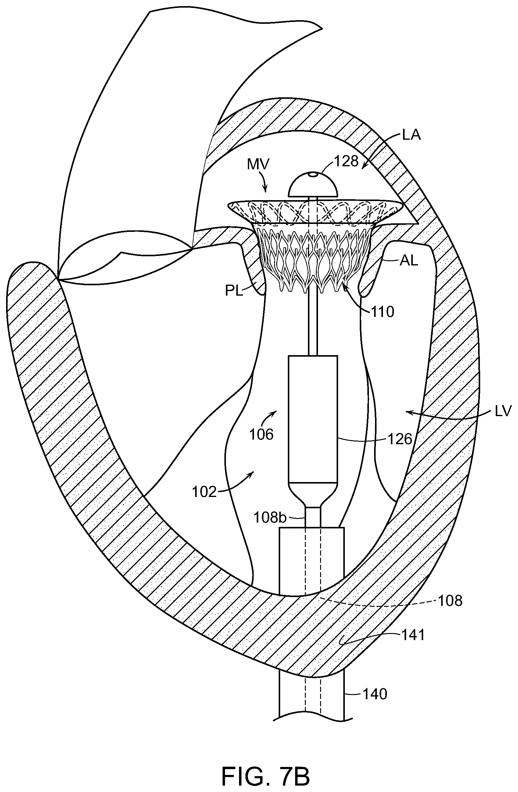
[0052] Once at a target location, the delivery capsule 106 can be hydraulically driven from the containment configuration (FIG. 7A) towards the deployment configuration (FIG. 7B) to partially or fully deploy the prosthetic heart valve device 110 from the delivery capsule 106. For example, as explained in further detail below, the delivery capsule 106 can be hydraulically driven towards the deployment configuration by supplying a flowable liquid to a chamber of the delivery capsule 106 while also removing a flowable liquid from a separate chamber of the delivery capsule 106. The hydraulically controlled movement of the delivery capsule 106 is expected to reduce, limit, or substantially eliminate uncontrolled deployment of the prosthetic heart valve device 110 caused by forces associated with expansion of the prosthetic heart valve device 110, such as jumping, self-ejection, and/or other types of uncontrolled movement. For example, the delivery capsule 106 is expected to inhibit or prevent translation of the prosthetic heart valve device 110 relative to the catheter body 108 while at least a portion of the prosthetic heart valve device 110 expands.
[0053] Referring to FIG. 7B, in trans-apical delivery approaches, the prosthetic heart valve device 110 is deployed from the delivery capsule 106 by drawing the housing 126 proximally (i.e., further into the left ventricle LV) and, optionally, moving the end cap 128 distally (i.e., further into the left atrium LA). As the prosthetic heart valve device 110 exits the housing 126, the device 110 expands and presses against tissue on an inner surface of the annulus of the mitral valve MV to secure the device 110 in the mitral valve MV. The catheter 102 is also configured to partially or fully resheathe the prosthetic heart valve device 110 after partial deployment from the delivery capsule 106. For example, the delivery capsule 106 can be hydraulically driven back towards the containment configuration by transferring fluid into one chamber of the delivery capsule 106 and removing fluid from another chamber of the delivery capsule 106 in an opposite manner as that used for deployment. This resheathing ability allows the clinician to re-position the prosthetic heart valve device 110, in vivo, for redeployment within the mitral valve MV or remove the prosthetic heart valve device 110 from the patient after partial deployment. After full deployment of the prosthetic heart valve device 110, the end cap 128 can be drawn through the deployed prosthetic heart valve device 110 to again close the delivery capsule 106 and draw the catheter 102 proximally through the guide catheter 140 for removal from the patient. After removing the catheter 102, it can be cleaned and used to deliver additional prosthetic devices or it can be discarded.
[0054] FIGS. 8A and 8B are partially schematic cross-sectional views of the delivery system 100 of FIG. 6 in the containment configuration (FIG. 8A) and the deployment configuration (FIG. 8B) in accordance with an embodiment of the present technology. As shown in FIGS. 8A and 8B, the distal portion 108b of the elongated catheter body 108 carries the delivery capsule 106. The delivery capsule 106 includes the housing 126 and a platform 142 that together define, at least in part, a first chamber 144a and a second chamber 144b (referred to collectively as "the chambers 144"). The first chamber 144a and the second chamber 144b are fluidically sealed from each other and from a compartment 146 in the housing 126 that is configured to contain the prosthetic heart valve device 110. The chambers 144 can be filled and drained to hydraulically drive the delivery capsule 106 between the containment configuration (FIG. 8A) for holding the prosthetic heart valve device 110 and the deployment configuration (FIG. 8B) for at least partially deploying the prosthetic heart valve device 100. As shown in FIG. 8A, for example, the housing 126 of the delivery capsule 106 is urged proximally (in the direction of arrow 153) towards the deployment configuration when fluid is at least partially drained from the first chamber 144a (as indicated by arrow 159) while fluid is being delivered to the second chamber 144b (as indicated by arrow 157). The proximal translation of the housing 126 allows the prosthetic heart valve device 110 to at least partially deploy from the housing 126 (FIG. 8B) and expand such that it may engage surrounding tissue of a native mitral valve. As shown in FIG. 8B, the housing 126 is urged distally back towards the containment configuration to resheathe at least a portion of the prosthetic heart valve device 110 when fluid is at least partially drained from the second chamber 144b (as indicated by arrow 161) while fluid is being delivered into the first chamber 144b (as indicated by arrow 163).
[0055] The platform 142 extends at least partially between the inner wall of the housing 126 to divide the housing 126 into the first chamber 144a and the second chamber 144b. The platform 142 can be integrally formed as a part of the housing 126, such as an inwardly extending flange. Thus, the platform 142 can be made from the same material as the housing 126 (e.g., metal, polymers, plastic, composites, combinations thereof, or other). In other embodiments, the platform 142 may be a separate component that at least partially separates the two chambers 144 from each other.
[0056] As shown in FIGS. 8A and 8B, a fluid delivery shaft 148 ("shaft 148") extends through the catheter body 108, into the housing 126 of the delivery capsule 106, and through the platform 142. At its proximal end (not shown), the shaft 148 is coupled to a fluid source (e.g., the fluid source 114 of FIG. 6) and includes one or more fluid lines 152 (identified individually as a first line 152a and a second line 152b) that can deliver and/or drain fluid to and/or from the chambers 144. The fluid lines 152 can be fluid passageways or lumens integrally formed within the shaft 148, such as channels through the shaft itself, or the fluid lines 152 may be tubes or hoses positioned within one or more hollow regions of the shaft 148. The first line 152a is in fluid communication with the first chamber 144a via a first opening 166a in the first fluid line 152a, and the second line 152b is in fluid communication with the second chamber 144b via a second opening 166b in the second fluid line 152b. In other embodiments, the first and second chambers 144a and 144b can be in fluid communication with more than one fluid line. For example, each chamber 144 may have a dedicated fluid delivery line and dedicated fluid drain line.
[0057] The shaft 148 can also include a first flange or pedestal 154a and a second flange or pedestal 154b (referred to together as "flanges 154") that extend outwardly from the shaft 148 to define the proximal and distal ends of the first and second chambers 144a and 144b, respectively. Accordingly, the first chamber 144a is defined at a distal end by a proximal-facing surface of the platform 142, at a proximal end by a distally-facing surface of the first flange 154a, and by the interior wall of the housing 126 extending therebetween. The second chamber 144b is defined at a proximal end by a distal-facing surface of the platform 142, at a distal end by a proximally-facing surface of the second flange 154b, and by the interior wall of the housing 126 extending therebetween. The compartment 146 containing the prosthetic heart valve device 110 can be defined by a distal-facing surface of the second flange 154b, the end cap 128, and the interior wall of the housing 126 extending therebetween. The shaft 148 and the flanges 154 can be integrally formed or separate components, and can be made from metal, polymers, plastic, composites, combinations thereof, and/or other suitable materials for containing fluids. The flanges 148 are fixed with respect to the shaft 148. Sealing members 156 (identified individually as first through third sealing members 156a-c, respectively), such as O-rings, can be positioned around or within the flanges 154 and/or the platform 142 to fluidically seal the chambers 144 from other portions of the delivery capsule 106. For example, the first and second sealing members 156a and 156b can be positioned in recesses of the corresponding first and second flanges 154a and 154b to fluidically seal the flanges 154 against the interior wall of the housing 126, and the third sealing member 156c can be positioned within a recess of the platform 142 to fluidically seal the platform 142 to the shaft 148. In other embodiments, the system 100 can include additional and/or differently arranged sealing members to fluidically seal the chambers 144.
[0058] The fluid lines 152 are in fluid communication with a manifold 158 at a proximal portion of the system 100 and in communication with the fluid assembly 112 (FIG. 6). The manifold 158 may be carried by the control unit 104 (FIG. 6) or it may be integrated with the fluid assembly 112 (FIG. 6). As shown in FIGS. 8A and 8B, the manifold 158 can include a fluid delivery lumen 160 that bifurcates to allow for delivery of fluid to the first and second fluid lines 152a and 152b and a drain lumen 162 that bifurcates to allow for removal of fluid from the first and second fluid lines 152a and 152b. The delivery lumen 160 and the drain lumen 162 can be placed in fluid communication with the fluid source 114 (FIG. 6) to allow fluid to move between the fluid source 114 to the chambers 144. In other embodiments, each fluid line 152 can have a dedicated delivery lumen and a dedicated drain lumen, which are in turn fluidly coupled to separate fluid reservoirs in the fluid source 114 (FIG. 6).
[0059] The manifold 158 further includes one or more valves 164 (referred to individually as a first valve 164a and a second valve 164b) that regulate fluid flow to and from the chambers 144. The first valve 164a is in fluid communication with the first fluid line 152a, the delivery lumen 160 (or a portion thereof), and the drain line 162 (or a portion thereof) to regulate fluid to and from the first chamber 144a. The second valve 164b is in fluid communication with the second fluid line 152b, the delivery lumen 160 (or a portion thereof), and the drain line 162 (or a portion thereof) to regulate fluid to and from the second chamber 144b. The valves 164 can be three-way valves and/or other suitable valves for regulating fluid to and from the fluid lines 152.
[0060] As shown in FIG. 8A, in the initial containment configuration, the first chamber 144a is at least partially filled with fluid and the second chamber 144b includes little to no fluid. To fully or partially unsheathe the prosthetic heart valve device 110, the second valve 164b opens the second fluid line 152b and closes the drain line 162. This allows fluid to flow from the delivery lumen 160, through the second fluid line 152b, and into the second chamber 144b via the second opening 166b (as indicated by arrows 157), while simultaneously blocking fluid from draining into the drain line 162. As fluid is delivered to the second chamber 144b, fluid also drains from the first chamber 144a. To do this, the first valve 164a closes the first line 152a proximal to the first valve 164a (i.e., such that the first line 152a is not in fluid communication with the delivery lumen 160) and opens the drain lumen 162 so that fluid exits the first chamber 144a via the first opening 166a, travels along the first fluid line 152a, and into the drain lumen 162 via the first valve 164a (as indicated by arrows 159). In certain embodiments, fluid is transferred to the second chamber 144b and from the first chamber 144a simultaneously and, optionally, in equal quantities so that the same amount of fluid transferred out of the first chamber 144a is transferred into the second chamber 144b. In other embodiments, different amounts of fluid are drained from and transferred to the chambers 144. This concurrent transfer of fluid into the second chamber 144b while draining fluid from the first chamber 144a drives the housing 126 proximally in the direction of arrow 153, which unsheathes the prosthetic heart valve device 110 and allows it to at least partially expand. As shown in FIG. 8B, this proximal movement of the housing 126 creates an open chamber 170 defined by the distal facing surface of the housing 126 and the proximal-facing surface of the flange 154a.
[0061] As shown in FIG. 8B, during deployment of the prosthetic heart valve device 110, the delivery capsule 106 axially restrains an outflow portion of the prosthetic heart valve device 110 while an inflow portion of the prosthetic heart valve device 110 is deployed from the delivery capsule 106. After at least partial deployment, the fluid chambers 144 can be pressurized and drained in an inverse manner to move the housing 126 distally (in the direction of arrow 155) back toward the containment configuration and at least partially resheathe the prosthetic heart valve device 110. For resheathing, the second valve 164b is placed in fluid communication with the drain lumen 162 and closes the second fluid line 152b proximal to the second valve 164b so that fluid drains from the second chamber 144b via the second opening 166b, through the second fluid line 152b, and into the drain lumen 162 (as indicated by arrows 161). As fluid exits the second chamber 144b, fluid is also delivered to the first chamber 144a. That is, the first valve 164a is placed in fluid communication with the delivery lumen 160 to deliver fluid into the first chamber 144a via the first opening 166a of the first fluid line 152a (as indicated by arrows 163). Again, the fluid can be transferred simultaneously and/or in equal proportions from the second chamber 144b and to the first chamber 144a. This transfer of fluid into the first chamber 144a and from the second chamber 144b drives the housing 126 distally in the direction of arrow 155 to controllably resheathe the prosthetic heart valve device 110 such that at least a portion of the prosthetic heart valve device 110 is again positioned within the compartment 146. This partial or full resheathing of the prosthetic heart valve device 110 allows a clinician to reposition or remove the prosthetic heart valve device 110 after partial deployment. The hydraulic movement of the housing 126 is expected to provide controlled deployment and resheathing of the prosthetic heart valve device 110.
[0062] As the delivery capsule 106 moves between the containment configuration and the deployment configuration, the housing 126 moves slideably with respect to the longitudinal axis of the shaft 148, while the prosthetic heart valve device 110 at least substantially maintains its longitudinal position relative to the catheter body 108. That is, the delivery capsule 106 can substantially prevent longitudinal translation of the prosthetic heart valve device 110 relative to the catheter body 108 while the prosthetic heart valve device 110 moves between the containment configuration (FIG. 8A) and the deployment configuration (FIG. 8B). This allows the clinician to position the sheathed prosthetic heart valve device 110 at the desired target site for deployment, and then deploy the device 110 at that target site without needing to compensate for any axial movement of the device 110 as it reaches full expansion (e.g., as would need to be taken into account if the device 110 was pushed distally from the housing 126).
[0063] As further shown in FIGS. 8A and 8B, the system 100 may also include a biasing device 168 that acts on the housing 126 to urge the housing 126 toward the containment configuration. The biasing device 168 compresses as the housing 126 moves to the deployment configuration (FIG. 8B) to apply more force on the housing 126 in a distal direction toward the containment configuration. In certain embodiments, the biasing device 168 acts continuously on the housing 126 urging it toward the containment configuration, and in other embodiments the biasing device 168 only acts on the housing 126 as it is compressed during deployment. In the illustrated embodiment, the biasing device 168 is a spring, but in other embodiments the biasing device can include other features that urge the housing 126 toward the containment configuration. The biasing device 168 limits or substantially prevents opening of the delivery capsule 106 attributable to the forces produced by the expanding prosthetic heart valve device 110. For example, an unsheathed portion of the prosthetic heart valve device 110 can expand outwardly from the partially opened delivery capsule 106 while the biasing device 168 inhibits further opening of the delivery capsule 106.
[0064] The system 100 shown in FIGS. 8A and 8B allows for delivery of the prosthetic heart valve device 110 to a mitral valve from the left ventricle (e.g., via a trans-apical approach shown in FIGS. 7A and 7B). For example, the hydraulic delivery mechanism moves the housing 126 proximally toward the distal portion 108b of the catheter body 108 to deploy the prosthetic heart valve device 110 (e.g., as shown in FIG. 7A), and once the prosthetic heart valve device 110 is fully deployed, the end cap 128 can be moved proximally from the left atrium and into the left ventricle through the deployed device 110.
[0065] FIGS. 9A and 9B are side cross-sectional views of a distal portion of a delivery system 200 for a prosthetic heart valve device 110 in a retained state (FIG. 9A) and in a fully deployed state (FIG. 9B) in accordance with another embodiment of the present technology. The delivery system 200 can include various features at least generally similar to the features of the system 100 described above with reference to FIGS. 6-8B. For example, the delivery system 200 can be hydraulically driven by moving fluid to and from two separate chambers 144 (only the second chamber 144b shown in FIGS. 9A and 9B) to move the housing 126 between deployment and containment configurations. The delivery system 200 also includes the fluid delivery shaft 148 with flanges 154 that define the outer bounds of the chambers 144.
[0066] The delivery system 200 of FIGS. 9A and 9B further includes an engagement device 272 that is configured to maintain engagement between the delivery capsule 106 and the prosthetic heart valve device 110 after the prosthetic heart valve device 110 has been at least partially expanded. The engagement device 272 includes a shaft 274 that extends through (e.g., coaxially within) or alongside at least a portion of the fluid delivery shaft 148 and is controllable by a clinician from a proximal portion of the delivery system 200 (e.g., via the control unit 104 of FIG. 6). The shaft 274 can be a central or engagement shaft that includes a distal region 273 having a pedestal 276 with one or more engagement or attachment elements 278 that releasably mate with corresponding attachment features 280 extending from the outflow region of the prosthetic heart valve device 110.
[0067] The attachment elements 278 can be recesses or pockets that retain correspondingly shaped attachment features 280 (e.g., pins or projections) on an outflow region of the prosthetic heart valve device 110. For example, the attachment elements 278 can be circular pockets that receive eyelet-shaped attachment features 280 extending from the outflow region of the prosthetic heart valve device 110 and/or the attachment elements 278 can be T-shaped recesses that receive corresponding T-shaped attachment features 280 extending from the outflow region of the prosthetic heart valve device 110.
[0068] FIG. 9C is a top view of the pedestal 276 illustrating one arrangement of the attachment elements 278. The illustrated pedestal 276 includes four T-shaped recesses 281 spaced 90.degree. apart from each other around the periphery of the pedestal 276 and circular pockets 283 spaced between the T-shaped recesses 281. The T-shaped recesses 281 may extend deeper into the pedestal 276 than the circular pockets 283 (e.g., as shown in FIGS. 9A and 9B), or the attachment elements 278 can have similar depths. In other embodiments, the pedestal 276 has different quantities and/or arrangements of T-shaped recesses 281 and/or the circular pockets 283 across the face of the pedestal 276. In further embodiments, the pedestal 276 can include differently shaped recesses and pockets that releasably mate with correspondingly-shaped attachment features on the prosthetic heart valve device 110. In still further embodiments, the engagement device 272 includes other features that releasably attach the prosthetic heart valve device 110 to the delivery system 200 before final release from the delivery system 200.
[0069] In the embodiment illustrated in FIGS. 9A and 9B, the second flange 154b includes a projection 282 that forms a recess 284 facing the prosthetic heart valve device 110, and the recess 284 at least partially receives the pedestal 276 to retain the attachment features 280 with the attachment elements 278. The projection 282 may extend toward the prosthetic heart valve device 110 beyond the surface of the pedestal 276 positioned therein such that the projection 282 at least partially constrains an end region of the prosthetic heart valve device 110 before full deployment. In other embodiments, the second flange 154b does not include the projection 282, and the pedestal 276 abuts an end surface of the second flange 154b and/or other outward-facing feature of the delivery capsule 106.
[0070] In operation, a clinician moves the delivery capsule 106 to the target site (e.g., in a native mitral valve) and hydraulically moves the housing 126 to unsheathe and at least partially expand the prosthetic heart valve device 110. When the prosthetic heart valve device 110 is substantially expanded (FIG. 9A), the engagement device 272 holds the prosthetic heart valve device 110 to the delivery system 200 in case the device 110 needs to be resheathed for repositioning or redeployment. This allows the clinician to again partially or fully resheathe the prosthetic heart valve device 110 to adjust its position or orientation with respect to the native valve. Referring to FIG. 9B, after the prosthetic heart valve device 110 is partially deployed at the appropriate location, the clinician can move the engagement shaft 274 in the direction of arrow 285 away from the remainder of the delivery capsule 106 and out of the recess 284 (e.g., in a distal direction when deployed trans-apically). This movement releases the mateably received attachment features 280 on the prosthetic heart valve device 110 from the corresponding attachment elements 278 to fully release the prosthetic heart valve device 110 from the delivery system 200. For example, the expansion of the previously restrained proximal-most portion of the prosthetic heart valve device 110 (e.g., restrained by the projection 282 of the flange 154b) results in a force that disengages the attachment features 280 from the attachment elements 278 and allows the device 110 to fully expand. In other embodiments, the engagement shaft 274 can remain stationary with respect to the prosthetic heart valve device 110 and the delivery capsule 106 (e.g., the housing 126, the flange 154b, etc.) can be moved away from the prosthetic heart valve device 110 (e.g., in a proximal direction when the device is deployed trans-apically) to disengage the attachment features 280 from the attachment elements 278.
[0071] FIGS. 10A-10C are a series of partially schematic illustrations of a distal portion of a hydraulic delivery system 300 deploying a prosthetic a prosthetic heart valve device 310 within a native mitral valve of a heart using a trans-septal approach in accordance with further embodiments of the present technology. The hydraulic delivery system 300 can include certain features generally similar the delivery systems 100, 200 described above with reference to FIGS. 6-9C. For example, the delivery system 300 includes a catheter 302 having an elongated catheter body 308 and a delivery capsule 306 at a distal portion 308b of the catheter body 308. The proximal portion of the catheter 302 can be coupled to a fluid system (e.g., the fluid assembly 112 of FIG. 6) and/or a manifold (e.g., the manifold 158 of FIGS. 8A and 8B) to hydraulically move the delivery capsule 306 between a containment configuration and a deployment configuration. The delivery system 300 facilitates trans-septal delivery of the prosthetic heart valve device 310 to the native mitral valve MV.
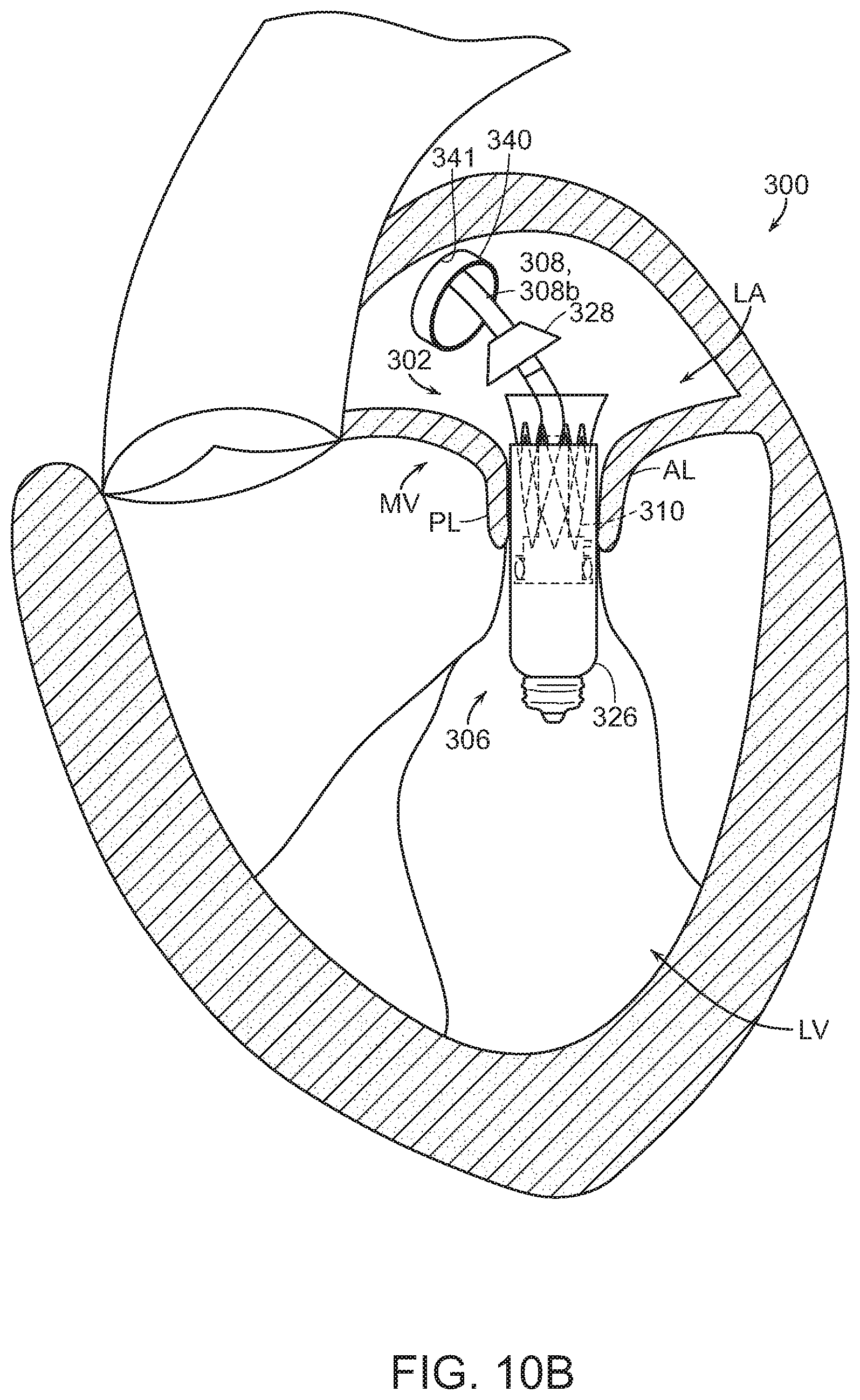
[0072] Referring to FIG. 10A, a puncture or opening 341 can be formed in an atrial region of a septum of the heart to access the left atrium LA. A guide catheter 340 can be positioned through the opening 341, and a guidewire 320 can extend through the guide catheter 340, through the mitral valve MV, and into the left ventricle LV. A delivery capsule 306 at a distal portion 308b of the elongated catheter body 308 can then be delivered to the left atrium LA from the guide catheter 340, advanced along the guidewire 320, and positioned at a target site between the posterior and anterior leaflets PL and AL of the mitral valve MV.
[0073] As shown in FIG. 10B, once at the target site in the mitral valve MV, the prosthetic heart valve device 310 can be deployed by removing a proximally positioned end cap 328 and moving a housing 326 of the delivery capsule 306 in a distal direction (i.e., downstream further into the left ventricle LV). In certain embodiments, fluid can be delivered and removed to/from chambers (not shown) of the delivery capsule 306 to hydraulically move the housing 326 toward the deployment configuration. This distal movement unsheathes the upstream or inflow portion of the prosthetic heart valve device 310 while the downstream or ventricular end of the prosthetic heart valve device 310 remains constrained within the housing 326. The unsheathed inflow portion can expand outward to contact tissue of the mitral valve MV. If the clinician elects to adjust the positioning of the prosthetic heart valve device 310, fluid can be delivered to and removed from the delivery capsule chambers in an opposite manner to hydraulically move the housing 326 toward the containment configuration and at least partially resheathe the prosthetic heart valve device 310. After the deployed inflow portion of the prosthetic heart valve device 310 is appropriately seated in the mitral valve MV, fluid can again be delivered to and removed from the delivery capsule chambers to again move the housing 326 distally toward the deployment configuration. As shown in FIG. 10C, fluid can be delivered/removed until the housing 326 fully unsheathes the prosthetic heart valve device 310 and the prosthetic heart valve device 310 expands against the mitral valve MV. In the fully deployed state, the delivery capsule 306 can then be returned to the containment configuration (e.g., with the housing 326 and the end cap 328 joined together), pulled through the left atrium LA, and removed from the heart.
[0074] In other embodiments, the system 100 of FIGS. 6-8B can be reconfigured to allow for deployment from the left atrium (e.g., via the trans-septal approach shown in FIGS. 10A-10C) in which case the housing 126 with the first and second chambers 144a and 144b has the opposite orientation shown in FIGS. 8A and 8B. That is, the end cap 128 is positioned adjacent to the distal portion 108b of the catheter body 108 and the housing 126 is located distally from the end cap 128 with the shaft 148 extending through or adjacent to the device 110 to allow fluid delivery to the chambers 144. To deploy the prosthetic heart valve device 110, fluid is removed from the first fluid chamber 144a while fluid is delivered to the second fluid chamber 144b, which moves the housing 126 distally (further into the left ventricle) to at least partially unsheathe the prosthetic heart valve device 110. To resheathe the prosthetic heart valve device 110, fluid is removed from the second fluid chamber 144b while fluid is delivered to the first fluid chamber 144a, moving the housing 126 proximally (toward the catheter body 108) toward the containment configuration.
[0075] FIGS. 11A and 11B are enlarged, partially schematic cross-sectional views of a distal portion of the trans-septal delivery system 300 in a partially expanded deployment configuration (FIG. 11A) and a resheathing or containment configuration (FIG. 11B) in accordance with an embodiment of the present technology. As discussed above, the delivery system 300 includes the delivery capsule 306 coupled to the distal portion 308b of the catheter body 308. The delivery capsule 306 includes the housing 326 and a platform 342 that define, at least in part, a first or deployment chamber 344a. The delivery system 300 further includes expandable member 390 coupled to the catheter body 308 and distal to the delivery capsule 306. The interior of the expandable member 390 defines a second or resheathing chamber 344b. The expandable member 390 can be a balloon or other expandable component in which a fluid can be contained and removed. The delivery system 300 can also include sealing features 356 (identified individually as a first sealing features 356a and a second sealing feature 356b), such as O-rings, to fluidically seal the deployment chamber 344a from a containment compartment 346 (FIG. 11B) in the housing 326 that carries the prosthetic heart valve device 310 and the expandable member 390. In other embodiments, the delivery system 300 can include additional sealing features for fluidically sealing the deployment chamber 344a and the resheathing chamber 344b.
[0076] As further shown in FIGS. 11A and 11B, a fluid delivery shaft 348 extends through the housing 326 and into the expandable member 390. The fluid delivery shaft 348 includes at least a first fluid line 352a in fluid communication with the deployment chamber 344a via a first opening 366a and a second fluid line 352b in fluid communication with the resheathing chamber 344b via a second opening 366b. The proximal portions of the fluid lines 352 can be in fluid communication with a manifold (not shown; e.g., the manifold 158 of FIGS. 8A and 8B) and/or a fluid system (not shown; e.g., the fluid assembly 112 of FIG. 6) to allow fluid to be delivered to and removed from the deployment and resheathing chambers 344a and 344b. In other embodiments, the first fluid line 352a and the second fluid line 352b can be separate components, such as two fluid delivery/removal shafts, one in fluid communication with the deployment chamber 344a and one in fluid communication with the resheathing chamber 344b. The fluid delivery shaft 348 can extend through the catheter body 308, adjacent to the catheter body 308. In other embodiments, the fluid delivery shaft 348 is omitted and the fluid lines 352 can be separate components that extend through the catheter body 308.
[0077] In various embodiments, the delivery system 300 can further include a distal end cap 392 positioned distal to the expandable member 390 and coupled to the distal portion 308b of the catheter body 308 and/or the fluid delivery shaft 348. The distal end cap 392 can be configured to seal the distal end of the expandable member 390 and/or may have an atraumatic shape (e.g., frusto-conical, partially spherical, etc.) to facilitate atraumatic delivery of the delivery capsule 306 to the target site. As shown in FIGS. 11A and 11B, the distal end cap 392 can also include an opening 330 that allows for guidewire delivery of the delivery capsule 306 to the target site.
[0078] The delivery capsule 306 can be hydraulically driven between a containment configuration in which the prosthetic heart valve device 310 is held in the compartment 346 of the housing 326 and the deployment configuration in which at least a portion of the prosthetic heart valve device 310 expands from the compartment 346. More specifically, in an initial containment state (e.g., as the delivery capsule 306 is delivered to the target site), the prosthetic heart valve device 310 is held in the compartment 346 of the housing 326 and the expandable member 390 is at least substantially empty (e.g., the configuration of the expandable member 390 shown in FIG. 11A). To begin deployment, fluid is delivered to the deployment chamber 344a via the first line 352a (e.g., as indicated by arrows 391 in FIG. 11A). Providing fluid to the deployment chamber 344a increases the pressure therein, thereby moving the housing 326 distally relative to the platform 342 and unsheathing the prosthetic heart valve device 310 (beginning with the atrial or inflow portion of the device 310). This unsheathing mechanism at least substantially prevents translation of the prosthetic heart valve device 310 relative to the catheter body 308 and the surrounding anatomy to facilitate positioning and deployment of the device 310.
[0079] As shown in FIG. 11B, the prosthetic heart valve device 310 can be at least partially resheathed after at least partial deployment. To resheathe the device 310, fluid is drained or removed from deployment chamber 344a (as indicated by arrows 393), while fluid is delivered to the expandable member 390 via the second line 352b (as indicated by arrows 395). The expansion of the expandable member 390 urges the housing 326 towards the containment configuration such that the prosthetic heart valve device 310 is at least partially resheathed and again positioned at least partially in the compartment 346 of the housing 326 (FIG. 11B). Accordingly, the delivery system 300 provides for controlled, hydraulic delivery of the prosthetic heart valve device 310 via a trans-septal delivery approach and also inhibits translation of the prosthetic heart valve device 310 during deployment and resheathing to facilitate accurate delivery to the target site.
Selected Embodiments of Prosthetic Heart Valve Devices
[0080] The hydraulic delivery systems 100, 200, 300 described above with reference to FIGS. 6-11B can be configured to deliver various prosthetic heart valve devices, such as prosthetic valve devices for replacement of the mitral valve and/or other valves (e.g., a bicuspid or tricuspid valve) in the heart of the patient. Examples of these prosthetic heart valve devices, system components, and associated methods are described in this section with reference to FIGS. 12A-25. Specific elements, substructures, advantages, uses, and/or other features of the embodiments described with reference to FIGS. 12A-25 can be suitably interchanged, substituted or otherwise configured with one another. Furthermore, suitable elements of the embodiments described with reference to FIGS. 12A-25 can be used as stand-alone and/or self-contained devices.
[0081] FIG. 12A is a side cross-sectional view and FIG. 12B is a top plan view of a prosthetic heart valve device ("device") 1100 in accordance with an embodiment of the present technology. The device 1100 includes a valve support 1110, an anchoring member 1120 attached to the valve support 1110, and a prosthetic valve assembly 1150 within the valve support 1110. Referring to FIG. 12A, the valve support 1110 has an inflow region 1112 and an outflow region 1114. The prosthetic valve assembly 1150 is arranged within the valve support 1110 to allow blood to flow from the inflow region 1112 through the outflow region 1114 (arrows BF), but prevent blood from flowing in a direction from the outflow region 1114 through the inflow region 1112.
[0082] In the embodiment shown in FIG. 12A, the anchoring member 1120 includes a base 1122 attached to the outflow region 1114 of the valve support 1110 and a plurality of arms 1124 projecting laterally outward from the base 1122. The anchoring member 1120 also includes a fixation structure 1130 extending from the arms 1124. The fixation structure 1130 can include a first portion 1132 and a second portion 1134. The first portion 1132 of the fixation structure 1130, for example, can be an upstream region of the fixation structure 1130 that, in a deployed configuration as shown in FIG. 12A, is spaced laterally outward apart from the inflow region 1112 of the valve support 1110 by a gap G. The second portion 1134 of the fixation structure 1130 can be a downstream-most portion of the fixation structure 1130. The fixation structure 1130 can be a cylindrical ring (e.g., straight cylinder or conical), and the outer surface of the fixation structure 1130 can define an annular engagement surface configured to press outwardly against a native annulus of a heart valve (e.g., a mitral valve). The fixation structure 1130 can further include a plurality of fixation elements 1136 that project radially outward and are inclined toward an upstream direction. The fixation elements 1136, for example, can be barbs, hooks, or other elements that are inclined only in the upstream direction (e.g., a direction extending away from the downstream portion of the device 1100).
[0083] Referring still to FIG. 12A, the anchoring member 1120 has a smooth bend 1140 between the arms 1124 and the fixation structure 1130. For example, the second portion 1134 of the fixation structure 1130 extends from the arms 1124 at the smooth bend 1140. The arms 1124 and the fixation structure 1130 can be formed integrally from a continuous strut or support element such that the smooth bend 1140 is a bent portion of the continuous strut. In other embodiments, the smooth bend 1140 can be a separate component with respect to either the arms 1124 or the fixation structure 1130. For example, the smooth bend 1140 can be attached to the arms 1124 and/or the fixation structure 1130 using a weld, adhesive or other technique that forms a smooth connection. The smooth bend 1140 is configured such that the device 1100 can be recaptured in a capsule or other container after the device 1100 has been at least partially deployed.
[0084] The device 1100 can further include a first sealing member 1162 on the valve support 1110 and a second sealing member 1164 on the anchoring member 1120. The first and second sealing members 1162, 1164 can be made from a flexible material, such as Dacron.RTM. or another type of polymeric material. The first sealing member 1162 can cover the interior and/or exterior surfaces of the valve support 1110. In the embodiment illustrated in FIG. 12A, the first sealing member 1162 is attached to the interior surface of the valve support 1110, and the prosthetic valve assembly 1150 is attached to the first sealing member 1162 and commissure portions of the valve support 1110. The second sealing member 1164 is attached to the inner surface of the anchoring member 1120. As a result, the outer annular engagement surface of the fixation structure 1130 is not covered by the second sealing member 1164 so that the outer annular engagement surface of the fixation structure 1130 directly contacts the tissue of the native annulus.
[0085] The device 1100 can further include an extension member 1170. The extension member 1170 can be an extension of the second sealing member 1164, or it can be a separate component attached to the second sealing member 1164 and/or the first portion 1132 of the fixation structure 1130. The extension member 1170 can be a flexible member that, in a deployed state (FIG. 12A), flexes relative to the first portion 1132 of the fixation structure 1130. In operation, the extension member 1170 provides tactile feedback or a visual indicator (e.g., on echocardiographic or fluoroscopic imaging systems) to guide the device 1100 during implantation such that the device 1100 is located at a desired elevation and centered relative to the native annulus. As described below, the extension member 1170 can include a support member, such as a metal wire or other structure, that can be visualized via fluoroscopy or other imaging techniques during implantation. For example, the support member can be a radiopaque wire.
[0086] FIGS. 13A and 13B are cross-sectional views illustrating an example of the operation of the smooth bend 1140 between the arms 1124 and the fixation structure 1130 in the recapturing of the device 1100 after partial deployment. FIG. 13A schematically shows the device 1100 loaded into a capsule 1700 of a delivery system in a delivery state, and FIG. 13B schematically shows the device 1100 in a partially deployed state. Referring to FIG. 13A, the capsule 1700 has a housing 1702, a pedestal or support 1704, and a top 1706. In the delivery state shown in FIG. 13A, the device 1100 is in a low-profile configuration suitable for delivery through a catheter or cannula to a target implant site at a native heart valve.
[0087] Referring to FIG. 13B, the housing 1702 of the capsule 1700 has been moved distally such that the extension member 1170, fixation structure 1130 and a portion of the arms 1124 have been released from the housing 1702 in a partially deployed state. This is useful for locating the fixation structure 1130 at the proper elevation relative to the native valve annulus A such that the fixation structure 1130 expands radially outward into contact the inner surface of the native annulus A. However, the device 1100 may need to be repositioned and/or removed from the patient after being partially deployed. To do this, the housing 1702 is retracted (arrow R) back toward the fixation structure 1130. As the housing 1702 slides along the arms 1124, the smooth bend 1140 between the arms 1124 and the fixation structure 1130 allows the edge 1708 of the housing 1702 to slide over the smooth bend 1140 and thereby recapture the fixation structure 1130 and the extension member 1170 within the housing 1702. The device 1100 can then be removed from the patient or repositioned for redeployment at a better location relative to the native annulus A. Further aspects of prosthetic heart valve devices in accordance with the present technology and their interaction with corresponding delivery devices are described below with reference to FIGS. 14-25.
[0088] FIG. 14 is a top isometric view of an example of the device 1100. In this embodiment, the valve support 1110 defines a first frame (e.g., an inner frame) and fixation structure 1130 of the anchoring member 1120 defines a second frame (e.g., an outer frame) that each include a plurality of structural elements. The fixation structure 1130, more specifically, includes structural elements 1137 arranged in diamond-shaped cells 1138 that together form at least a substantially cylindrical ring when freely and fully expanded as shown in FIG. 14. The structural elements 1137 can be struts or other structural features formed from metal, polymers, or other suitable materials that can self-expand or be expanded by a balloon or other type of mechanical expander.
[0089] In several embodiments, the fixation structure 1130 can be a generally cylindrical fixation ring having an outwardly facing engagement surface. For example, in the embodiment shown in FIG. 14, the outer surfaces of the structural elements 1137 define an annular engagement surface configured to press outwardly against the native annulus in the deployed state. In a fully expanded state without any restrictions, the walls of the fixation structure 1130 are at least substantially parallel to those of the valve support 1110. However, the fixation structure 1130 can flex inwardly (arrow I) in the deployed state when it presses radially outwardly against the inner surface of the native annulus of a heart valve.
[0090] The embodiment of the device 1100 shown in FIG. 14 includes the first sealing member 1162 lining the interior surface of the valve support 1110, and the second sealing member 1164 along the inner surface of the fixation structure 1130. The extension member 1170 has a flexible web 1172 (e.g., a fabric) and a support member 1174 (e.g., metal or polymeric strands) attached to the flexible web 1172. The flexible web 1172 can extend from the second sealing member 1164 without a metal-to-metal connection between the fixation structure 1130 and the support member 1174. For example, the extension member 1170 can be a continuation of the material of the second sealing member 1164. Several embodiments of the extension member 1170 are thus a malleable or floppy structure that can readily flex with respect to the fixation structure 1130. The support member 1174 can have a variety of configurations and be made from a variety of materials, such as a double-serpentine structure made from Nitinol.
[0091] FIG. 15 is a side view and FIG. 16 is a bottom isometric view of the device 1100 shown in FIG. 14. Referring to FIG. 15, the arms 1124 extend radially outward from the base portion 1122 at an angle .alpha. selected to position the fixation structure 1130 radially outward from the valve support 1110 (FIG. 14) by a desired distance in a deployed state. The angle .alpha. is also selected to allow the edge 1708 of the delivery system housing 1702 (FIG. 13B) to slide from the base portion 1122 toward the fixation structure 1130 during recapture. In many embodiments, the angle .alpha. is 15.degree.-75.degree., or more specifically 15.degree.-60.degree., or still more specifically 30.degree.-45.degree.. The arms 1124 and the structural elements 1137 of the fixation structure 1130 can be formed from the same struts (i.e., formed integrally with each other) such that the smooth bend 1140 is a continuous, smooth transition from the arms 1124 to the structural elements 1137. This is expected to enable the edge 1708 of the housing 1702 to more readily slide over the smooth bend 1140 in a manner that allows the fixation structure 1130 to be recaptured in the housing 1702 of the capsule 1700 (FIG. 13B). Additionally, by integrally forming the arms 1124 and the structural elements 1137 with each other, it inhibits damage to the device 1100 at a junction between the arms 1124 and the structural elements 1137 compared to a configuration in which the arms 1124 and structural elements 1137 are separate components and welded or otherwise fastened to each other.
[0092] Referring to FIGS. 15 and 16, the arms 1124 are also separated from each other along their entire length from where they are connected to the base portion 1122 through the smooth bend 1140 (FIG. 15) to the structural elements 1137 of the fixation structure 1130. The individual arms 1124 are thus able to readily flex as the edge 1708 of the housing 1702 (FIG. 13B) slides along the arms 1124 during recapture. This is expected to reduce the likelihood that the edge 1708 of the housing 1702 will catch on the arms 1124 and prevent the device 1100 from being recaptured in the housing 1702.
[0093] In one embodiment, the arms 1124 have a first length from the base 1122 to the smooth bend 1140, and the structural elements 1137 of the fixation structure 1130 at each side of a cell 1138 (FIG. 14) have a second length that is less than the first length of the arms 1124. The fixation structure 1130 is accordingly less flexible than the arms 1124. As a result, the fixation structure 1130 is able to press outwardly against the native annulus with sufficient force to secure the device 1100 to the native annulus, while the arms 1124 are sufficiently flexible to fold inwardly when the device is recaptured in a delivery device.
[0094] In the embodiment illustrated in FIGS. 14-16, the arms 1124 and the structural elements 1137 are configured such that each arm 1124 and the two structural elements 1137 extending from each arm 1124 formed a Y-shaped portion 1142 (FIG. 16) of the anchoring member 1120. Additionally, the right-hand structural element 1137 of each Y-shaped portion 1142 is coupled directly to a left-hand structural element 1137 of an immediately adjacent Y-shaped portion 1142. The Y-shaped portions 1142 and the smooth bends 1140 are expected to further enhance the ability to slide the housing 1702 along the arms 1124 and the fixation structure 1130 during recapture.
[0095] FIG. 17 is a side view and FIG. 18 is a bottom isometric view of a prosthetic heart valve device ("device") 1200 in accordance with another embodiment of the present technology. The device 1200 is shown without the extension member 1170 (FIGS. 14-16), but the device 1200 can further include the extension member 1170 described above. The device 1200 further includes extended connectors 1210 projecting from the base 1122 of the anchoring member 1120. Alternatively, the extended connectors 1210 can extend from the valve support 1110 (FIGS. 12A-16) in addition to or in lieu of extending from the base 1122 of the anchoring member 1120. The extended connectors 1210 can include a first strut 1212a attached to one portion of the base 1122 and a second strut 1212b attached to another portion of the base 1122. The first and second struts 1212a-b are configured to form a V-shaped structure in which they extend toward each other in a downstream direction and are connected to each other at the bottom of the V-shaped structure. The V-shaped structure of the first and second struts 1212a-b causes the extension connector 1210 to elongate when the device 1200 is in a low-profile configuration within the capsule 1700 (FIG. 13A) during delivery or partial deployment. When the device 1200 is fully released from the capsule 1700 (FIG. 13A) the extension connectors 1210 foreshorten to avoid interfering with blood flow along the left ventricular outflow tract.
[0096] The extended connectors 1210 further include an attachment element 1214 configured to releasably engage a delivery device. The attachment element 1214 can be a T-bar or other element that prevents the device 1200 from being released from the capsule 1700 (FIG. 13A) of a delivery device until desired. For example, a T-bar type attachment element 1214 can prevent the device 1200 from moving axially during deployment or partial deployment until the housing 1702 (FIG. 13A) moves beyond the portion of the delivery device engaged with the attachment elements 1214. This causes the attachment elements 1214 to disengage from the capsule 1700 (FIG. 13A) as the outflow region of the valve support 1110 and the base 1122 of the anchoring member 1120 fully expand to allow for full deployment of the device 1200.
[0097] FIG. 19 is a side view and FIG. 20 is a bottom isometric view of the device 1200 in a partially deployed state in which the device 1200 is still capable of being recaptured in the housing 1702 of the delivery device 1700. Referring to FIG. 19, the device 1200 is partially deployed with the fixation structure 1130 substantially expanded but the attachment elements 1214 (FIG. 17) still retained within the capsule 1700. This is useful for determining the accuracy of the position of the device 1200 and allowing blood to flow through the functioning replacement valve during implantation while retaining the ability to recapture the device 1200 in case it needs to be repositioned or removed from the patient. In this state of partial deployment, the elongated first and second struts 1212a-b of the extended connectors 1210 space the base 1122 of the anchoring member 1120 and the outflow region of the valve support 1110 (FIG. 12A) apart from the edge 1708 of the capsule 1700 by a gap G.
[0098] Referring to FIG. 20, the gap G enables blood to flow through the prosthetic valve assembly 1150 while the device 1200 is only partially deployed. As a result, the device 1200 can be partially deployed to determine (a) whether the device 1200 is positioned correctly with respect to the native heart valve anatomy and (b) whether proper blood flow passes through the prosthetic valve assembly 1150 while the device 1200 is still retained by the delivery system 1700. As such, the device 1200 can be recaptured if it is not in the desired location and/or if the prosthetic valve is not functioning properly. This additional functionality is expected to significantly enhance the ability to properly position the device 1200 and assess, in vivo, whether the device 1200 will operate as intended, while retaining the ability to reposition the device 1200 for redeployment or remove the device 1200 from the patient.
[0099] FIG. 21 is an isometric view of a valve support 1300 in accordance with an embodiment of the present technology. The valve support 1300 can be an embodiment of the valve support 1110 described above with respect to FIGS. 12A-20. The valve support 1300 has an outflow region 1302, an inflow region 1304, a first row 1310 of first hexagonal cells 1312 at the outflow region 1302, and a second row 1320 of second hexagonal cells 1322 at the inflow region 1304. For purposes of illustration, the valve support shown in FIG. 21 is inverted compared to the valve support 1110 shown in FIGS. 12A-20 such that the blood flows through the valve support 1300 in the direction of arrow BF. In mitral valve applications, the valve support 1300 would be positioned within the anchoring member 1120 (FIG. 12A) such that the inflow region 1304 would correspond to orientation of the inflow region 1112 in FIG. 12A and the outflow region 1302 would correspond to the orientation of the outflow region 1114 in FIG. 12A.
[0100] Each of the first hexagonal cells 1312 includes a pair of first longitudinal supports 1314, a downstream apex 1315, and an upstream apex 1316. Each of the second hexagonal cells 1322 can include a pair of second longitudinal supports 1324, a downstream apex 1325, and an upstream apex 1326. The first and second rows 1310 and 1312 of the first and second hexagonal cells 1312 and 1322 are directly adjacent to each other. In the illustrated embodiment, the first longitudinal supports 1314 extend directly from the downstream apexes 1325 of the second hexagonal cells 1322, and the second longitudinal supports 1324 extend directly from the upstream apexes 1316 of the first hexagonal cells 1312. As a result, the first hexagonal cells 1312 are offset from the second hexagonal cells 1322 around the circumference of the valve support 1300 by half of the cell width.
[0101] In the embodiment illustrated in FIG. 21, the valve support 1300 includes a plurality of first struts 1331 at the outflow region 1302, a plurality of second struts 1332 at the inflow region 1304, and a plurality of third struts 1333 between the first and second struts 1331 and 1332. Each of the first struts 1331 extends from a downstream end of the first longitudinal supports 1314, and pairs of the first struts 1331 are connected together to form first downstream V-struts defining the downstream apexes 1315 of the first hexagonal cells 1312. In a related sense, each of the second struts 1332 extends from an upstream end of the second longitudinal supports 1324, and pairs of the second struts 1332 are connected together to form second upstream V-struts defining the upstream apexes 1326 of the second hexagonal cells 1322. Each of the third struts 1333 has a downstream end connected to an upstream end of the first longitudinal supports 1314, and each of the third struts 1333 has an upstream end connected to a downstream end of one of the second longitudinal supports 1324. The downstream ends of the third struts 1333 accordingly define a second downstream V-strut arrangement that forms the downstream apexes 1325 of the second hexagonal cells 1322, and the upstream ends of the third struts 1333 define a first upstream V-strut arrangement that forms the upstream apexes 1316 of the first hexagonal cells 1312. The third struts 1333, therefore, define both the first upstream V-struts of the first hexagonal cells 1312 and the second downstream V-struts of the second hexagonal cells 1322.
[0102] The first longitudinal supports 1314 can include a plurality of holes 1336 through which sutures can pass to attach a prosthetic valve assembly and/or a sealing member. In the embodiment illustrated in FIG. 21, only the first longitudinal supports 1314 have holes 1336. However, in other embodiments the second longitudinal supports 1324 can also include holes either in addition to or in lieu of the holes 1336 in the first longitudinal supports 1314.
[0103] FIG. 22 is a side view and FIG. 23 is a bottom isometric view of the valve support 1300 with a first sealing member 1162 attached to the valve support 1300 and a prosthetic valve 1150 within the valve support 1300. The first sealing member 1162 can be attached to the valve support 1300 by a plurality of sutures 1360 coupled to the first longitudinal supports 1314 and the second longitudinal supports 1324. At least some of the sutures 1360 coupled to the first longitudinal supports 1314 pass through the holes 1336 to further secure the first sealing member 1162 to the valve support 1300.
[0104] Referring to FIG. 23, the prosthetic valve 1150 can be attached to the first sealing member 1162 and/or the first longitudinal supports 1314 of the valve support 1300. For example, the commissure portions of the prosthetic valve 1150 can be aligned with the first longitudinal supports 1314, and the sutures 1360 can pass through both the commissure portions of the prosthetic valve 1150 and the first sealing member 1162 where the commissure portions of the prosthetic valve 1150 are aligned with a first longitudinal support 1314. The inflow portion of the prosthetic valve 1150 can be sewn to the first sealing member 1162.
[0105] The valve support 1300 illustrated in FIGS. 21-23 is expected to be well suited for use with the device 1200 described above with reference to FIGS. 17-20. More specifically, the first struts 1331 cooperate with the extended connectors 1210 (FIGS. 17-20) of the device 1200 to separate the outflow portion of the prosthetic valve 1150 from the capsule 1700 (FIGS. 19-20) when the device 1200 is in a partially deployed state. The first struts 1331, for example, elongate when the valve support 1300 is not fully expanded (e.g., at least partially contained within the capsule 1700) and foreshorten when the valve support is fully expanded. This allows the outflow portion of the prosthetic valve 1150 to be spaced further apart from the capsule 1700 in a partially deployed state so that the prosthetic valve 1150 can at least partially function when the device 1200 (FIGS. 17-20) is in the partially deployed state. Therefore, the valve support 1300 is expected to enhance the ability to assess whether the prosthetic valve 1150 is fully operational in a partially deployed state.
[0106] FIGS. 24 and 25 are schematic side views of valve supports 1400 and 1500, respectively, in accordance with other embodiments of the present technology. Referring to FIG. 24, the valve support 1400 includes a first row 1410 of first of hexagonal cells 1412 and a second row 1420 of second hexagonal cells 1422. The valve 1400 can further include a first row 1430 of diamond-shaped cells extending from the first hexagonal cells 1412 and a second row 1440 of diamond-shaped cells extending from the second hexagonal cells 1422. The additional diamond-shaped cells elongate in the low-profile state, and thus they can further space the prosthetic valve 1150 (shown schematically) apart from a capsule of a delivery device. Referring to FIG. 25, the valve support 1500 includes a first row 1510 of first hexagonal cells 1512 at an outflow region 1502 and a second row 1520 of second hexagonal cells 1522 at an inflow region 1504. The valve support 1500 is shaped such that an intermediate region 1506 (between the inflow and outflow regions 1502 and 1504) has a smaller cross-sectional area than that of the outflow region 1502 and/or the inflow region 1504. As such, the first row 1510 of first hexagonal cells 1512 flares outwardly in the downstream direction and the second row 1520 of second hexagonal cells 1522 flares outwardly in the upstream direction.
EXAMPLES
[0107] Several aspects of the present technology are set forth in the following examples.
[0108] 1. A system for delivering a prosthetic heart valve device into a heart of a patient, the system comprising: [0109] an elongated catheter body; and [0110] a delivery capsule carried by the elongated catheter body and configured to be hydraulically driven between a containment configuration for holding the prosthetic heart valve device and a deployment configuration for at least partially deploying the prosthetic heart valve device, [0111] wherein the delivery capsule includes a housing and a platform, and wherein-- [0112] the housing and the platform define, at least in part, a first chamber and a second chamber, [0113] at least a portion of the delivery capsule is urged towards the deployment configuration when fluid is at least partially drained from the first chamber while fluid is delivered into the second chamber, and [0114] at least a portion of the delivery capsule is urged towards the containment configuration to resheathe at least a portion of the prosthetic heart valve device when fluid is at least partially drained from the second chamber and delivered into the first chamber.
[0115] 2. The system of example 1, further comprising a manifold at a proximal end region of the elongated catheter body and configured to receive the fluid for delivery to the first and/or second chambers, wherein the manifold comprises a first fluid lumen and first valve in fluid communication with the first chamber, and a second fluid lumen and a second valve in fluid communication with the second chamber.
[0116] 3. The system of example 2 wherein the first and second valves are three-way valves.
[0117] 4. The system of example 2 wherein the manifold is configured to be external to the patient during a implantation procedure.
[0118] 5. The system of example 2 wherein the first fluid lumen is fluidly isolated from the second fluid lumen.
[0119] 6. The system of any one of examples 1-5 wherein the delivery capsule is configured to axially restrain the prosthetic heart valve device while a first portion of the prosthetic heart valve device is deployed from the delivery capsule and to release an axially restrained portion of the prosthetic heart valve device while the first portion of the prosthetic heart valve device contacts tissue of a native valve of the heart of the patient.
[0120] 7. The system of any one of examples 1-6 wherein the delivery capsule is configured to substantially prevent translation of the prosthetic heart valve device relative to the elongated catheter body while the prosthetic heart valve device moves between the containment configuration and the deployment configuration.
[0121] 8. The system of any one of examples 1-7, further comprising a biasing device positioned along the catheter body and configured to urge the delivery capsule towards the containment configuration.
[0122] 9. The system of example 8 wherein the biasing device comprises a spring positioned to be compressed as the delivery capsule moves towards the deployment configuration to deploy the prosthetic heart valve device when fluid is transferred to the first chamber.
[0123] 10. The system of any one of examples 1-9, further comprising an engagement shaft extending through at least a portion of the elongated catheter body, wherein a distal end region of the engagement shaft is releasably coupled to the prosthetic heart valve device via one or more attachment elements, and wherein the one or attachment elements comprise pockets configured to mate with corresponding attachment features of the prosthetic heart valve device.
[0124] 11. The system of example 10 wherein the attachment features comprise eyelet shaped projections configured to releasably engage corresponding pockets at the distal end region of the engagement shaft.
[0125] 12. The system of example 10 wherein the attachment features comprise T-shaped projections configured to releasably mate with corresponding T-shaped pockets at the distal end region of the engagement shaft.
[0126] 13. A system for delivering a prosthetic heart valve device for implantation at a native heart valve of a patient, the system comprising: [0127] an elongated catheter body; [0128] a delivery capsule coupled to the elongated catheter body and configured to contain the prosthetic heart valve device, wherein-- [0129] the delivery capsule is configured to be hydraulically driven between a containment configuration for holding the prosthetic heart valve device and a deployment configuration for deploying at least a portion of the prosthetic heart valve device, [0130] the delivery capsule includes a housing and a platform that define, at least in part, a deployment chamber; and [0131] an expandable member coupled to the elongated catheter body and distal to the delivery capsule, wherein the expandable member is configured to urge the delivery capsule towards the containment configuration and resheathe at least a portion of the prosthetic heart valve device when fluid is at least partially drained from the deployment chamber while fluid is delivered to the expandable member.
[0132] 14. The system of example 13 wherein the delivery capsule is configured to substantially prevent translation of the prosthetic heart valve device relative to the elongated catheter body while the prosthetic heart valve device is at least partially resheathed.
[0133] 15. The system of example 13 or 14 wherein the delivery capsule further comprises a containment chamber configured to contain the prosthetic heart valve device, and wherein the containment chamber is fluidically sealed from the deployment chamber via the platforml.
[0134] 16. The system of any one of examples 13-15 wherein the expandable member is a balloon.
[0135] 17. A method for delivering a prosthetic heart valve device to a native mitral valve of a heart of a human patient, the method comprising: [0136] positioning a delivery capsule of an elongated catheter body within the heart, the delivery capsule carrying the prosthetic heart valve device; [0137] delivering fluid to a first chamber within the delivery capsule to move the prosthetic heart valve device from a containment configuration within the delivery capsule to a deployment configuration, wherein the first chamber is proximal to the prosthetic heart valve device; [0138] while fluid is delivered to the first chamber, draining fluid from a second chamber within the delivery capsule, wherein the second chamber is proximal to the prosthetic heart valve device; and [0139] allowing the prosthetic heart valve device to radially expand to engage tissue of the native mitral valve when the delivery capsule moves from the containment configuration towards the deployment configuration.
[0140] 18. The method of example 17, further comprising: [0141] urging the delivery capsule toward the containment configuration to resheathe the prosthetic heart valve device after allowing the prosthetic heart valve device to at least partially radially expand, wherein urging the delivery capsule toward the containment configuration comprises-- [0142] draining fluid from the first chamber; and [0143] while draining fluid from the first chamber, delivering fluid to the second chamber.
[0144] 19. The method of example 17 or 18 wherein: [0145] delivering fluid to the first chamber comprises delivering fluid from a manifold at a proximal portion of the elongated catheter body via a first fluid lumen; and [0146] draining fluid from the second chamber comprises removing fluid via a second fluid lumen to the manifold.
[0147] 20. The method of any one of examples 17-19 wherein delivering fluid to the first chamber and draining fluid from the second chamber at least substantially prevents translation of the prosethetic heart valve device relative to the elongated catheter body while the prosthetic heart valve device moves from the containment configuration to the deployment configuration.
[0148] 21. The method of any one of examples 17-20, further comprising restraining a distal portion of the prosthetic heart valve device as the prosthetic heart valve device moves between the containment and deployment configurations, wherein the distal portion of the prosthetic heart valve device comprises attachment elements that releasably couple to pockets at a distal end region of an engagement shaft that extends through the elongated catheter body.
[0149] 22. The method of example 21, further comprising moving the engagement shaft distally relative to the delivery capsule to release the restrained distal portion of the distal end region of the engagement shaft and fully expand the prosthetic heart valve device.
CONCLUSION
[0150] The above detailed descriptions of embodiments of the technology are not intended to be exhaustive or to limit the technology to the precise form disclosed above. Although specific embodiments of, and examples for, the technology are described above for illustrative purposes, various equivalent modifications are possible within the scope of the technology as those skilled in the relevant art will recognize. For example, although steps are presented in a given order, alternative embodiments may perform steps in a different order. The various embodiments described herein may also be combined to provide further embodiments.
[0151] From the foregoing, it will be appreciated that specific embodiments of the technology have been described herein for purposes of illustration, but well-known structures and functions have not been shown or described in detail to avoid unnecessarily obscuring the description of the embodiments of the technology. Where the context permits, singular or plural terms may also include the plural or singular term, respectively.
[0152] Moreover, unless the word "or" is expressly limited to mean only a single item exclusive from the other items in reference to a list of two or more items, then the use of "or" in such a list is to be interpreted as including (a) any single item in the list, (b) all of the items in the list, or (c) any combination of the items in the list. Additionally, the term "comprising" is used throughout to mean including at least the recited feature(s) such that any greater number of the same feature and/or additional types of other features are not precluded. It will also be appreciated that specific embodiments have been described herein for purposes of illustration, but that various modifications may be made without deviating from the technology. Further, while advantages associated with certain embodiments of the technology have been described in the context of those embodiments, other embodiments may also exhibit such advantages, and not all embodiments need necessarily exhibit such advantages to fall within the scope of the technology. Accordingly, the disclosure and associated technology can encompass other embodiments not expressly shown or described herein.
* * * * *
D00000
D00001
D00002
D00003
D00004
D00005
D00006
D00007
D00008
D00009
D00010
D00011
D00012

D00013

D00014
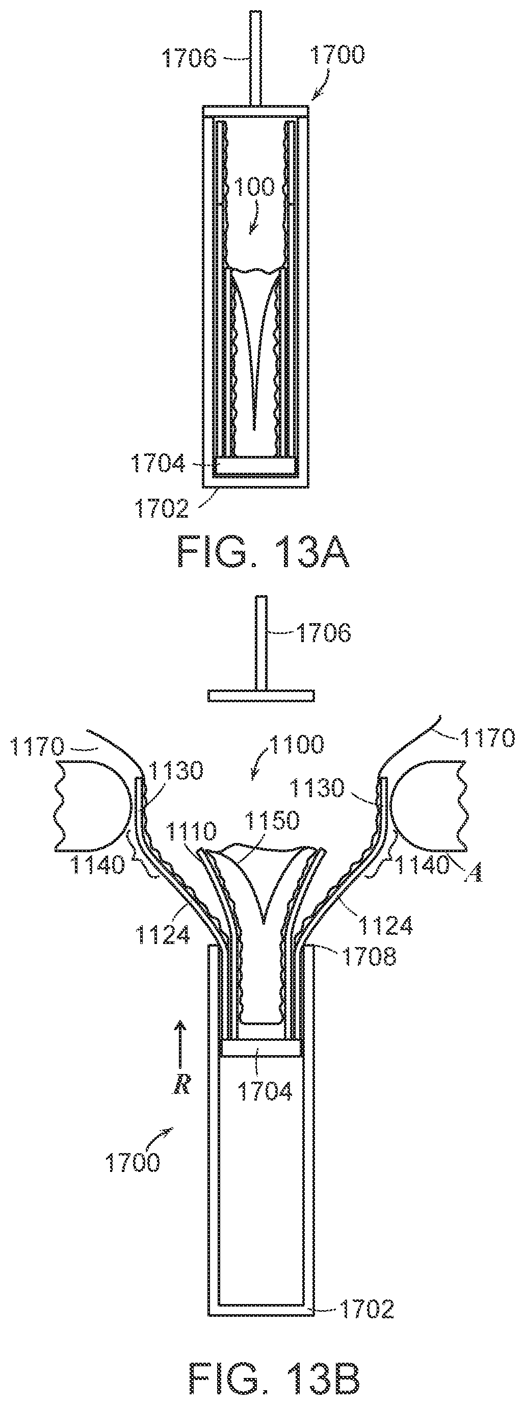
D00015
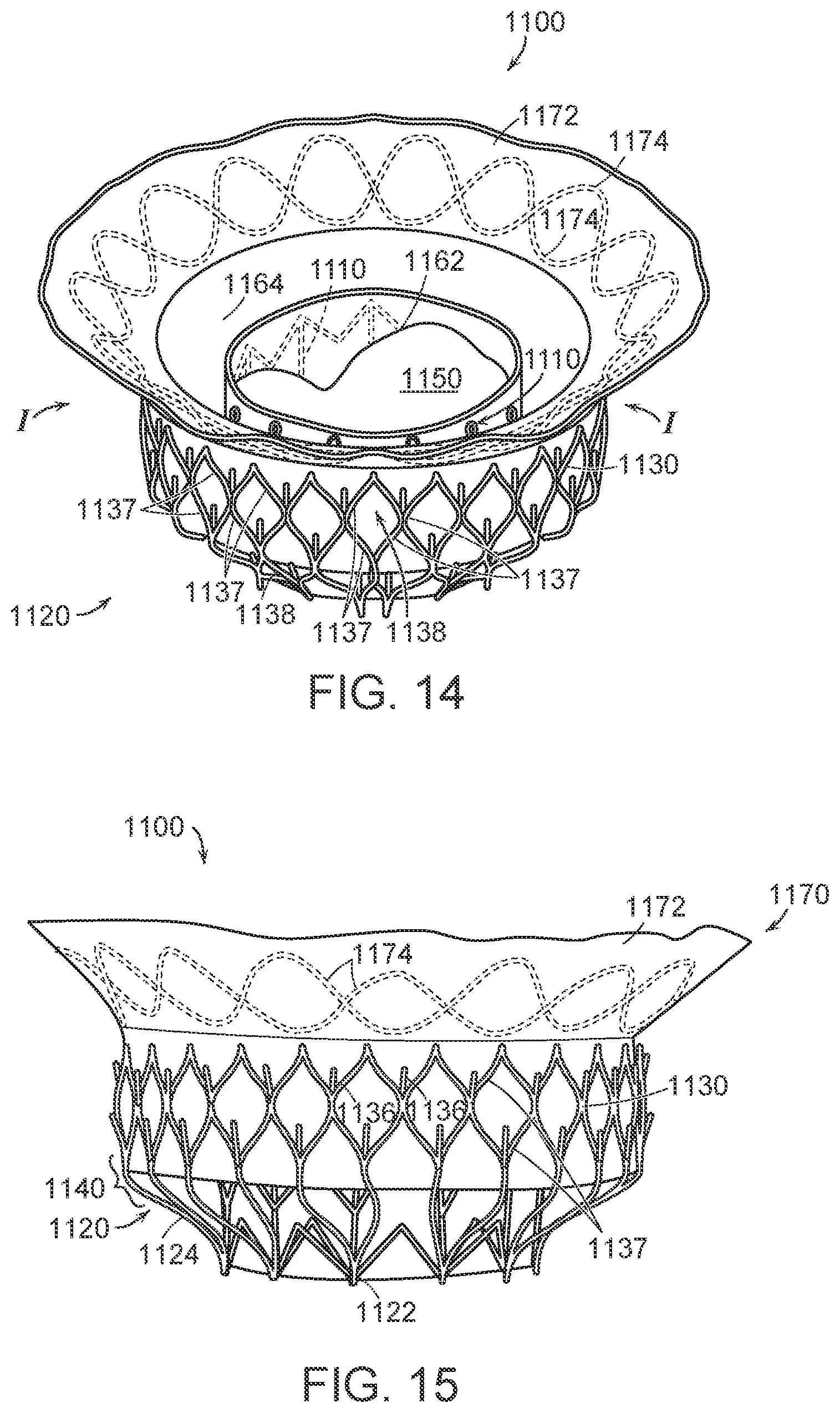
D00016
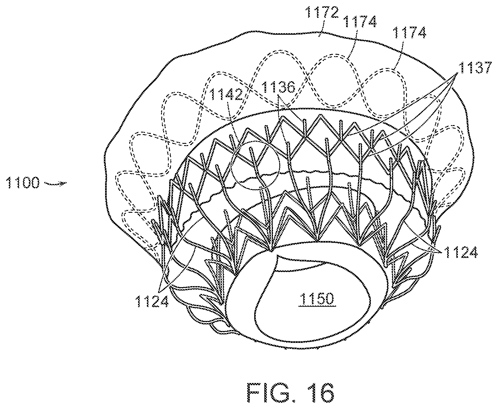
D00017
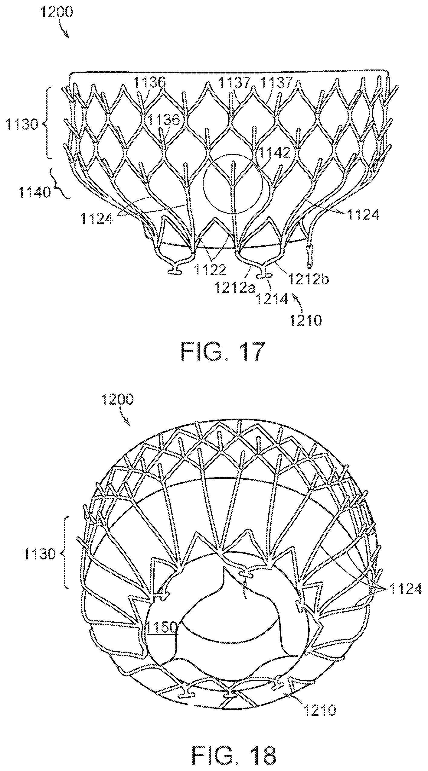
D00018

D00019

D00020

D00021

XML
uspto.report is an independent third-party trademark research tool that is not affiliated, endorsed, or sponsored by the United States Patent and Trademark Office (USPTO) or any other governmental organization. The information provided by uspto.report is based on publicly available data at the time of writing and is intended for informational purposes only.
While we strive to provide accurate and up-to-date information, we do not guarantee the accuracy, completeness, reliability, or suitability of the information displayed on this site. The use of this site is at your own risk. Any reliance you place on such information is therefore strictly at your own risk.
All official trademark data, including owner information, should be verified by visiting the official USPTO website at www.uspto.gov. This site is not intended to replace professional legal advice and should not be used as a substitute for consulting with a legal professional who is knowledgeable about trademark law.