Illuminating Feedback During Teeth Cleaning
Luettgen; Harold A. ; et al.
U.S. patent application number 16/749627 was filed with the patent office on 2020-05-21 for illuminating feedback during teeth cleaning. The applicant listed for this patent is WATER PIK, INC.. Invention is credited to John Fiers, Harold A. Luettgen, Brian R. Williams.
| Application Number | 20200155286 16/749627 |
| Document ID | / |
| Family ID | 60242758 |
| Filed Date | 2020-05-21 |


| United States Patent Application | 20200155286 |
| Kind Code | A1 |
| Luettgen; Harold A. ; et al. | May 21, 2020 |
ILLUMINATING FEEDBACK DURING TEETH CLEANING
Abstract
A toothbrush is disclosed. The toothbrush includes a handle, a brush tip coupled to the handle, the brush tip including a plurality of bristles, a motor housed within the handle for operating the brush tip, a power source coupled to the motor, one or more lights coupled to the handle and viewable by a user when holding the handle, and a control module housed within the handle and in communication with the one or more lights, wherein the control module is configured to monitor a pressure exerted by the brush tip on a surface, determine when the exerted pressure exceeds a pressure threshold, and, in response to the exerted pressure exceeding the pressure threshold, activate the one or more lights to alert the user that the exerted pressure exceeds the pressure threshold.
| Inventors: | Luettgen; Harold A.; (Windsor, CO) ; Fiers; John; (Fort Collins, CO) ; Williams; Brian R.; (Fort Collins, CO) | ||||||||||
| Applicant: |
|
||||||||||
|---|---|---|---|---|---|---|---|---|---|---|---|
| Family ID: | 60242758 | ||||||||||
| Appl. No.: | 16/749627 | ||||||||||
| Filed: | January 22, 2020 |
Related U.S. Patent Documents
| Application Number | Filing Date | Patent Number | ||
|---|---|---|---|---|
| 15588842 | May 8, 2017 | 10561480 | ||
| 16749627 | ||||
| 62333679 | May 9, 2016 | |||
| Current U.S. Class: | 1/1 |
| Current CPC Class: | A61C 17/3436 20130101; A61C 17/24 20130101; A61C 17/221 20130101; A61C 17/3418 20130101; A46B 15/0012 20130101; G01L 5/22 20130101 |
| International Class: | A61C 17/22 20060101 A61C017/22; A61C 17/24 20060101 A61C017/24; A61C 17/34 20060101 A61C017/34; G01L 5/22 20060101 G01L005/22; A46B 15/00 20060101 A46B015/00 |
Claims
1. A toothbrush comprising: a handle; a brush tip coupled to the handle, the brush tip including a plurality of bristles; a motor housed within the handle for operating the brush tip; a power source coupled to the motor; one or more lights coupled to the handle and viewable by a user when holding the handle; and a control module housed within the handle and in communication with the one or more lights, wherein the control module is configured to: monitor a pressure exerted by the brush tip on a surface; determine when the exerted pressure exceeds a pressure threshold; and in response to the exerted pressure exceeding the pressure threshold, activate the one or more lights to alert the user that the exerted pressure exceeds the pressure threshold.
2. The toothbrush of claim 1, wherein the one or more lights are one or more light emitting diodes.
3. The toothbrush of claim 1, wherein the pressure threshold is an absolute pressure magnitude value or a delta pressure value.
4. The toothbrush of claim 1, wherein the control module determines the pressure exerted by the brush tip by directly measuring force applied to the plurality of bristles.
5. The toothbrush of claim 1, wherein the control module determines the pressure exerted by the brush tip by indirectly measuring force applied to the plurality of bristles.
6. The toothbrush of claim 1, wherein the control module detects electrical current drawn by the motor and determines the exerted pressure based on the detected electrical current.
7. The toothbrush of claim 1, wherein the control module comprises one or more memory components that store the pressure threshold.
8. The toothbrush of claim 1, wherein the pressure threshold is between about 280 to about 430 g/cm.sup.2.
9. The toothbrush of claim 1, wherein the pressure threshold is about 140 g/cm.sup.2.
10. The toothbrush of claim 1, wherein the one or more lights provide feedback to a user to reduce pressure exerted by the brush tip.
11. A method of alerting a user of excessive pressure exerted by a toothbrush during teeth cleaning, comprising: determining a pressure exerted by bristles coupled to the toothbrush while the user is brushing teeth; determining that the exerted pressure is excessive; and activating a light on a handle of the toothbrush to provide feedback to the user that the pressure is excessive.
12. The method of claim 11, wherein the light is a light emitting diode.
13. The method of claim 11, wherein determining that the exerted pressure is excessive comprises determining that the exerted pressure exceeds a pressure threshold value.
14. The method of claim 11, wherein determining the pressure exerted by the bristles comprises directly measuring force applied to the bristles.
15. The method of claim 11, wherein determining the pressure exerted by the bristles comprises indirectly measuring force applied to the bristles.
16. The method of claim 11, wherein determining the pressure exerted by the bristles comprises detecting current drawn by a motor coupled to the bristles and correlating the detected current to a pressure value.
17. The method of claim 13, further comprising retrieving, from memory stored by the toothbrush, the pressure threshold value.
18. The method of claim 13, wherein the pressure threshold value is between about 280 to about 430 g/cm.sup.2.
19. The method of claim 13, wherein the pressure threshold value is about 140 g/cm.sup.2.
20. A toothbrush comprising: a handle; a brush tip including a plurality of bristles releasably coupled thereto; a motor received within the housing; a light coupled to the housing; and a control module positioned within the housing and in electrical communication with the light, wherein the control module is configured to: determine a pressure applied by the bristles to a tooth surface; and illuminate the light in response to the pressure being above a desired level.
Description
CROSS-REFERENCE TO RELATED APPLICATIONS
[0001] The present application is a continuation of U.S. Non-Provisional application Ser. No. 15/588,842, entitled "Load Sensing for Oral Devices" filed May 8, 2017, which claims priority to U.S. Provisional Application No. 62/333,679 entitled "Load Sensing for Oral Devices" filed on May 9, 2016, both of which are hereby incorporated by reference herein in their entireties.
TECHNICAL FIELD
[0002] The present disclosure relates to oral health products. More specifically, the present disclosure relates to toothbrush systems.
BACKGROUND
[0003] Many people use electronically driven toothbrushes as part of a daily oral health routine. Electronically driven toothbrushes typically rotate or oscillate a brush head include one or more bristle groups. While electronic toothbrushes can provide superior cleaning capabilities as compared to conventional non-powered toothbrushes, many users will exert an additional force on the brush head during cleaning. This user applied force, in addition to the force exerted by the stiffness and electronic movement of the bristles, can damage the gums of a user. Therefore, it is desirable to ensure that the force of the bristles on a user's gums remains below a particular level. However, many conventional electronically driven toothbrushes do not have a way to monitor or change the pressure exerted on a user's gums.
[0004] The information included in this Background section of the specification, including any references cited herein and any description or discussion thereof, is included for technical reference purposes only and is not to be regarded subject matter by which the scope of the invention as defined in the claims is to be bound.
SUMMARY
[0005] In one embodiment, a toothbrush including a pressure sensing function is disclosed. The toothbrush may include a handle and a brush tip releasably connected to the handle, where the brush tip includes multiple bristles connected thereto and rotatable therewith. The toothbrush may also include a power source, a direct current motor in selective communication with the power source, a drive assembly connected between the brush tip and a drive shaft that converts rotation of the direct current motor into oscillation or rotation of the brush tip, and a control assembly in electrical communication with the power source. During operation of the motor, the control assembly monitors a current draw by the motor to assess the pressure being exerted by the bristles on one or more surfaces of a user's mouth and adjusts a current applied to the direct current motor based on the current draw.
[0006] In another embodiment, a toothbrush including a pressure sensing function is disclosed. The toothbrush includes a brush tip comprising a plurality of bristles operably coupled thereto, a motor that actuates the brush tip, the plurality of bristles, or a combination thereof, a power source that provides current to the motor, a sensing module that detects a current provided to the motor, and a motor control coupled to the motor and the sensing module, wherein the motor control dynamically adjusts a current provided to the motor based on the detected current.
[0007] In another embodiment, a method of operating a toothbrush is disclosed. The method includes detecting, by a sensing module, a current provided to a motor driving a plurality of bristles on a brush tip, wherein the detected current is proportional to a pressure applied to the plurality of bristles, determining, by a processor, whether the detected current exceeds a threshold current, and providing an alert to a user responsive to determining that the detected current exceeds the threshold.
[0008] In another embodiment, a toothbrush is disclosed. The toothbrush includes a handle, a brush tip coupled to the handle, the brush tip including a plurality of bristles, a motor housed within the handle for operating the brush tip, a power source coupled to the motor, one or more lights coupled to the handle and viewable by a user when holding the handle, and a control module housed within the handle and in communication with the one or more lights. The control module is configured to monitor a pressure exerted by the brush tip on a surface, determine when the exerted pressure exceeds a pressure threshold, and, in response to the exerted pressure exceeding the pressure threshold, activate the one or more lights to alert the user that the exerted pressure exceeds the pressure threshold.
[0009] In another embodiment, a method of alerting a user of excessive pressure exerted by a toothbrush during teeth cleaning is disclosed. The method includes determining a pressure exerted by bristles coupled to the toothbrush while the user is brushing teeth, determining that the exerted pressure is excessive, and activating a light on the toothbrush handle to provide feedback to the user that the pressure is excessive.
[0010] In another embodiment, a toothbrush is disclosed. The toothbrush includes a handle, a brush tip including a plurality of bristles releasably coupled thereto, a motor received within the housing, a light coupled to the housing, and a control module positioned within the housing and in electrical communication with the light. The control module is configured to determine a pressure applied by the bristles to a tooth surface, and illuminate the light in response to the pressure being above a desired level.
[0011] This Summary is provided to introduce a selection of concepts in a simplified form that are further described below in the Detailed Description. This Summary is not intended to identify key features or essential features of the claimed subject matter, nor is it intended to be used to limit the scope of the claimed subject matter. A more extensive presentation of features, details, utilities, and advantages of the present invention as defined in the claims is provided in the following written description of various embodiments of the invention and illustrated in the accompanying drawings.
BRIEF DESCRIPTION OF THE DRAWINGS
[0012] FIG. 1 is a front elevation view of a toothbrush including a load sensing function.
[0013] FIG. 2 is a simplified block diagram of the electrically connected components of the toothbrush of FIG. 1.
[0014] FIG. 3 is a wiring diagram of a feedback loop for sensing the pressure applied to the bristles of the toothbrush.
[0015] FIG. 4 is a graph illustrating a relationship between motor current and pressure that can be used to adjust operation of the toothbrush.
[0016] FIG. 5 is a flow chart illustrating a method for using the pressure-current relationship of FIG. 4 and the feedback loop of FIG. 3 to adjust operation of the toothbrush of FIG. 1.
DETAILED DESCRIPTION
Overview
[0017] The present disclosure is generally related to a system and method to sense an applied load on a brush tip or bristles. Using this method, a toothbrush can provide an alert to a user to indicate that he or she has exceeded a desired force level and/or may automatically adjust one or more characteristics of the system to reduce the applied force, e.g., reduce the power applied to a motor driving the brush tip.
[0018] In one example, a toothbrush including a sensing module is disclosed. The toothbrush includes a direct-current (DC) driven motor, a drive assembly connected to and rotated by the motor, a power assembly for providing power to the motor, and a brush head or bristles connected to the drive assembly and configured to be oscillated or rotated by the drive assembly. In this example, the sensing module may monitor the voltage drop across the motor (e.g., by measuring the current that the motor is pulling from the power source) and use the value to determine the force being applied to a user's gums. In some embodiments, the sensing module may include parameters such as, but not limited to, type of brush tip, bristle stiffness, bristle height, no-load values, and the like. These additional parameters may assist in providing a more accurate reading for the toothbrush.
[0019] In a specific embodiment, the sensing module may monitor the voltage across a wire connected to the motor. Additionally or alternatively, the sensing module may monitor the voltage of an activating transistor electrically connected to the motor. The sensing modules may be connected to either or both the positive and negative terminals of the motor.
[0020] In some embodiments, the sensing module may analyze the detected values against a predetermined current/force relationship. In one embodiment, a linear slope relationship may be used to determine the force applied to the brush tip based on the current applied to the motor. In this example, as soon as the user applies the bristles of the brush tip to a surface in his or her mouth (e.g., gums, teeth, tongue, etc.), the sensing module tracks the current in real-time to adaptively track the motor load and thus the brush tip load, as it varies. An output to the user or a modification to the motor speed may occur when a detected load change exceeds a predetermined threshold, e.g., magnitude or change value. In some embodiments, the toothbrush may dynamically calculate a threshold level of pressure for a particular brush, using a current/force relationship, e.g., adaptive learning, and use this threshold to detect when the force may damage a user's gums. This helps to accommodate for changes based on wear on the components, bristles, new brush heads, and the like. If the threshold was based solely on a static level, rather than a dynamic relationship, then the threshold may not compensate for increases/decreases in friction and other changes in the brushes.
DETAILED DESCRIPTION
[0021] Turning now to the figures, the method and system will be discussed in more detail below. FIG. 1 illustrates a simplified diagram of a toothbrush of the present disclosure. FIG. 2 is a simplified electronic block diagram of the toothbrush of FIG. 1. With reference to FIGS. 1 and 2, the toothbrush 100 may include a handle 102 and a brush tip 104 including a brush head 106 having a plurality of bristles 108 connected thereto. The brush tip 104 is driven by an output shaft 110 connected to a drive assembly 116, which is connected via a drive shaft 114 to a motor 112. The motor 112 is powered by a power source 118 and is controlled by a control assembly 126 that may include user inputs through one or more control buttons 120. Each of the components will be discussed, in turn, below.
[0022] The handle 102 defines a main body of the toothbrush 100 and acts to house the various internal components (e.g., motor 112, drive assembly 116, etc.). In many embodiments the handle 102 may be formed by two shells that are connected together to define an internal cavity. However, in other embodiments the handle 102 may be differently configured. In some embodiments the toothbrush 100 may also include a washing or irrigating function and in these embodiments the handle 102 may include a fluid connection to a reservoir or the like, as well as one or more fluid pathways defined therein or connected thereto, that transfer fluid from the reservoir to the brush tip 104.
[0023] The brush head 104 is movable relative to the handle 102 and may be removably connected to a top end of the handle 102. The brush tip 104 is connected to the output shaft 110 which drives the brush head 104 in an oscillating motion (e.g., back and forth about a pivot point) or to drive the brush head 106 in a rotational movement relative to the handle 102. The brush tip 104 includes a plurality of bristles 108 that are connected to the brush head 106. The bristles 108 may be uniform or may have varying heights, stiffness, and/or materials in order to provide a desired output characteristic. As will be discussed in more detail below, in some embodiments various characteristics of the bristles 108 may be provided as an input or otherwise adjusted for by the toothbrush 100 when determining a desired motor 112 speed. For example, the stiffer the bristles 108 the slower the motor 112 may need to rotate to achieve a desired exertion force on a user's teeth and gums. It should be noted that in some embodiments, the entire brush head 104 may move in order to move the bristles 108 correspondingly. In other examples, the brush head 104 may connect to a bristle head or carrier that supports the bristles. In these examples, the bristle carrier only may move and the brush head may remain stationary.
[0024] The motor 112 is used to drive the brush tip 104 and/or brush head 106. In many embodiments the motor 112 is a high speed DC motor that, when activated, rotates the drive shaft 114 in a continuous manner. In some embodiments, the drive shaft 114 may be an eccentric shaft having one portion aligned with a center axis of the motor 112 and one portion offset from the center axis of the motor 112. In other embodiments, the drive shaft 114 may be straight and be aligned with the center axis of the motor 112. In some embodiments, the motor will rotate between 5500 to 16000 rpms depending on whether sonic or sub-sonic rotary motion is desired. In one example, a DC motor having a maximum efficiency load of 6900 rpms, a no-load speed of 8300 rpm, and a loaded speed of 5500 rpms may be used. However, in other embodiments, other speeds may be used and may vary depending on the desired output characteristics of the toothbrush 100. For example, using a direct drive assembly 116, the motor 112 may operate at higher speeds, such as 16000 rpms. In some embodiments, the motor 112 may operate with a voltage range between 2.4 to 8.7 Volts. However, in other embodiments other voltage ranges may be used.
[0025] The drive assembly 116 converts rotation of the drive shaft 114 into a desired output motion of the brush tip 104 and/or brush head 106. For example, the drive assembly 116 may convert the rotational movement of the drive shaft 114 into an oscillating movement of the brush tip 104. In another embodiment, the drive assembly 116 may transfer rotary motion of the drive shaft 114 into rotational movement of the brush head 106 relative to the brush tip 104. The drive assembly 116 may be a direct drive configuration or may be an indirect configuration (e.g., gear reduction or the like). Additionally, the drive assembly 116 may reduce the speed of the movement as compared to the rotational speed of the drive shaft 114. Examples of drive assemblies 116 that may be used with the toothbrush 100 may be found in U.S. patent application Ser. No. 13/833,897 entitled "Electronic Toothbrush with Vibration Dampening," filed on Mar. 15, 2013, U.S. Pat. No. 8,943,634 entitled "Mechanically-Driven, Sonic Toothbrush System," filed on May 2, 2012, U.S. patent application Ser. No. 14/216,779 entitled "Mechanically-Driven, Sonic Toothbrush and Water Flosser" filed on Mar. 17, 2014, and U.S. Provisional Application No. 62/190,094 entitled "Irrigating Toothbrush" filed on Jul. 8, 2015, each of which are hereby incorporated by reference in their entireties.
[0026] The output shaft 110 is connected to the drive assembly 116 and may include two or more shafts connected together. The output shaft 110 may be inserted into a cavity in the brush tip 104 to drive the motion of the brush tip 104 or may connect to an internal shaft within the brush tip 104.
[0027] The power source 118 provides power to the motor 112, as well as other components of the toothbrush 100 that may require power (e.g., control assembly 126, output elements 128, lights, or the like). In some embodiments the power source 118 may be a battery (either rechargeable or replaceable), in other embodiments the power source 118 may be a power cord or the like that connects to an external power source (e.g., wall outlet).
[0028] The control buttons 120 allow a user to provide input to control the operation of the motor 112. For example, the control buttons 120 may include a power button to allow a user to activate the motor 112. Additionally the control buttons 120 may include a speed or setting button that allows a user to increase or decrease the speed of the motor 112. In embodiments where the toothbrush 100 may have additional functions (e.g., irrigating function), the control buttons 120 may also change the functionality of the toothbrush 100, such as activating the fluid flow.
[0029] With reference to FIG. 2, the control assembly 126 will be discussed in more detail. The control assembly 126 is electronically connected to the motor 112, the power source 118, the control buttons 120, and one or more output elements 128 (e.g., light emitting diodes, speaker, vibrating motor, or the like). The control assembly 126 controls operation of the motor 112 and thus the output characteristics of the brush tip 104 and bristles 108. The control assembly 126 may include a motor control 124 that may include one or more processing elements (e.g., microprocessors) that vary the input signals to the motor 112 to provide a desired output, such as by providing a higher or lower voltage or a pulse width modulated signal. The control assembly 126 may also include one or more sensing modules 122 that directly or indirectly measure the force applied to the bristles 108 and one or more memory components 125 that store pressure thresholds and/or brush tip 104 characteristics.
[0030] The sensing module 122 provides feedback to the motor control 124 regarding the operation of the brush tip 104 and can be used to automatically vary the output of the motor 112 or to activate the output element 128. In one embodiment, the sensing module 122 tracks the mechanical load experienced on the bristles 108 by tracking the current applied to the motor 112. In one example, the sensing module 122 may be an in-series current sense that monitors the voltage across the motor wire connections (e.g., in the connection wire before or after the motor 112, such as the connection wires on the positive and negative side of the motor 112). For example, the current sense may include a current sensor (such as an ammeter), a voltage meter, or any other type of device capable of measuring, directly or indirectly, an electrical current. As another example, the sensing module 122 may be a motor-control sense that monitors the voltage of a control switch, such as a transistor (e.g., field effect transistor (FET)), using the inherent resistance during the on-state of the transistor (e.g., drain-source on resistance (R.sub.DS(on)). As yet another example, the sensing module 122 may include using a sensing resistor positioned in series with the motor 112 or to add additional lengths of wire traces to a circuit board including the various components. However, with the sensing resistor option, a drop in efficiency may occur due to the introduced loss through the resistor and therefore may not be desired in some configurations.
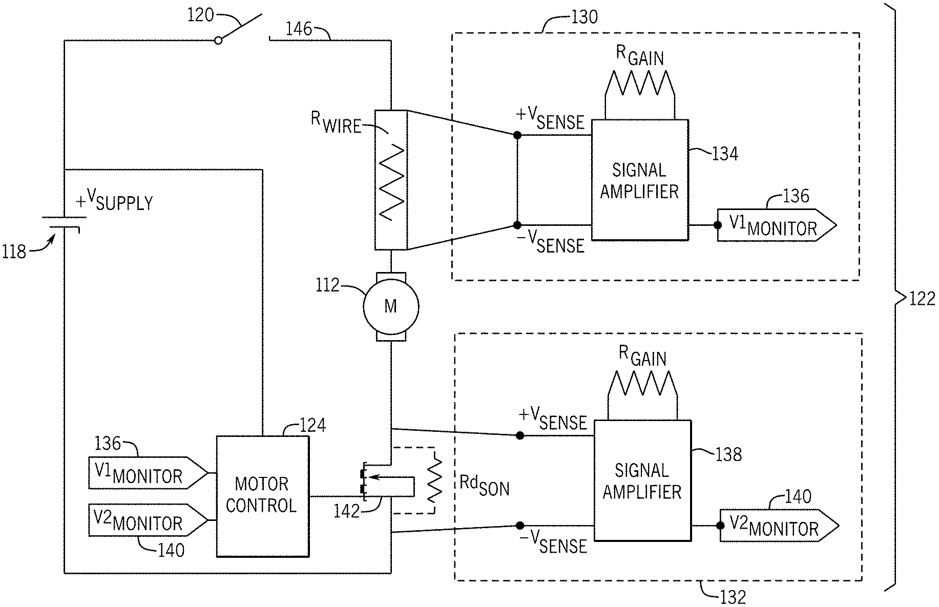
[0031] FIG. 3 illustrates an exemplary wiring diagram for the toothbrush 100. With reference to FIG. 3, in this embodiment, the sensing module 122 includes a positive sensing module 130 and a negative sensing module 132 which together form a feedback loop for the motor 112 operation. The positive sensing module 130 is positioned on the positive or high side of the motor 112, e.g., electrically connected to the positive terminal of the power source 118. The negative sensing module 132 is connected to the negative or low side of the motor 112, e.g., electrically connected to the negative terminal of the power source 118 and motor 112. Either or both sensing modules 130, 132 may be used to sense the current to the motor 112 and thus allow the motor control 124 to determine the load on the motor 112 and adjust accordingly and/or provide an alert or other output to the user.
[0032] In one embodiment, the positive sensing module 130 is an in-series current sense that monitors the voltage across the wire or trace connection 146 from the power source 118 to the positive terminal of the motor 112. In this example, the positive sensing module 130 may include a signal amplifier 134 that amplifies the detected signal before generating a first voltage output 136. As noted above, in other embodiments, the positive sensing module 130 may be differently configured and may be a current sense, rather than a voltage reference as shown point in FIG. 3.
[0033] With continued reference to FIG. 3, in this embodiment, the negative sensing module 132 may be a transistor or control sense. In this example, the negative sensing module 132 may monitor the voltage across a transistor 142, which may be a FET, using the drain-source resistance R.sub.DS(on) when the transistor 142 is in the on-state (e.g., allowing current to flow through the channel) and the motor 112 is operating. As with the positive sensing module 130, the negative sensing module 132 may include a signal amplifier 138 that amplifies the detected signal before generating a second voltage output 140. That is, the sensing module senses amplified voltages to monitor levels allowing operational closed loop feedback control.
[0034] As shown in FIG. 3, the voltage outputs 136, 140 may be supplied as inputs to the motor control 124. As will be discussed in more detail below, these inputs allow the toothbrush 100, and in particular, the motor control 124 to alert a user through the output elements 128 when the applied force exceeds a particular threshold and/or adjust the operation of the motor 112 accordingly.
[0035] Operation of the toothbrush 100 will now be discussed. With reference to FIGS. 1 and 2, when a user provides an input to the control buttons 120, a switch is closed to electrically connect the motor 112 to the power source 118. In some embodiments, the voltage level provided to the motor 112 is selected by the motor control 124. When powered, the motor 112 begins to operate, rotating the drive shaft 114. Rotation of the drive shaft 114 generates motion in the drive assembly 116 which converts the motion profile into a desired output movement. The output shaft 110, which is connected to the brush tip 104 moves the brush tip 104 in an oscillating or rotational manner, to move the bristles 108. In some embodiments the brush tip 104 may be rotated at a sonic speed to enhance cleaning.
[0036] As the user presses the bristles 108 against surfaces in his or her mouth, the added pressure provides a counteracting force on the motor causing the load on the motor 112 to increase. In particular, the harder the user presses the bristles 108 against a surface, the more torque the motor 112 may require in order to continue to rotate the bristles 108 at the desired or selected speed. In this manner, the current drawn by the motor 112 is proportional to the load (e.g., the force required to move the bristles 108), and as the load increases the current drawn by the motor 112 also increases.
[0037] By analyzing the motor current, along with other factors, such as characteristics of the brush tip 104, bristles 108 (e.g., strand thickness, tuft height (or heights when the brush head has groups of bristles with different heights), tuft counts, and the like), drive assembly 116, a relationship between the pressure exerted onto the applied surface as compared to the current drawn by the motor can be determined. FIG. 4 illustrates an exemplary graph illustrating a pressure-current relationship for the motor 112, where the pressure is measured in centimeter/gram/second units of g/cm.sup.2. As shown in FIG. 4, the pressure exerted on the interior surface (e.g., gums) of a user is related to the current drawn (in amps) by the motor 112 in a linear relationship 202. Using this relationship 202, the toothbrush 100, in particular, a processing element in the motor control 124, can determine or estimate the pressure being applied by the bristles 108 by monitoring the current of the motor 112. Specifically, the processing element may extrapolate an estimated pressure based on the detected current. The detected current may be from one or both sensing modules 130, 132.
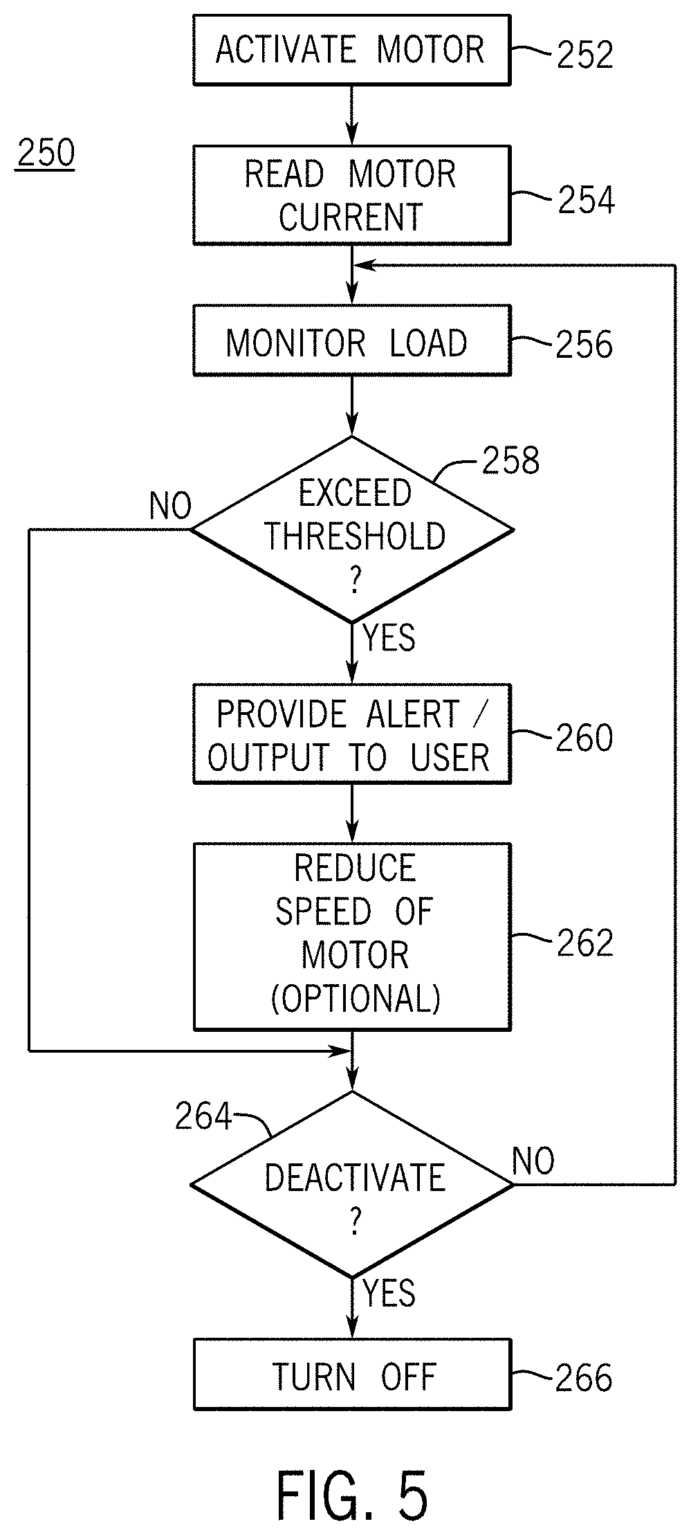
[0038] A method for using the pressure-current relationship 202 of FIG. 4 to adjust operation of the toothbrush 100 will now be discussed. FIG. 5 is a flow chart illustrating a method 250 for adjusting the operation of the toothbrush 100. With reference to FIG. 5, the method 250 may begin with operation 252 and the motor 112 is activated. For example, the use may activate one of the control buttons 120 which closes a connection between the power source 118 and the motor 112, providing voltage to the motor 112. As the motor 112 is activated, the method 250 proceeds to operation 254 and the control assembly 126 determines the current draw by the motor 112 shortly after start up. In particular, using the sensing module 122 (e.g., positive sensing module 130 and/or negative sensing module 132) the control assembly 126 (e.g., a processing element in the motor control 124) determines the current being drawn to the motor 112 by assessing the voltage drop across the motor and various sensing points in the control system 112, 146, 130, 132, 142. Operation 254 may be done just after start-up, since the initial current to start the motor may be higher than the no-load current. For example, the initial calibration may be performed within 50 ms of motor activation.
[0039] Operation 254 uses the motor current as the motor 112 is first activated to determine the no-load condition of the motor 112. In particular, as soon as the user activates the toothbrush 100, the system assumes that he or she has not yet positioned the bristles 108 against surfaces in his or her mouth, or if the user has positioned the bristles 108 against a surface, the pressure exerted manually by a user is very light. By creating an initial reading during operation 254, the method 250 can create a baseline value and account for variations in the toothbrush 100 over time. For example, normal operation may cause the drive assembly 116 and output shaft 110 to wear-in, reducing the friction on the motor 112 and thus reducing the no-load conditions on the motor 112. As another example, as a user's bristles 108 wear due to use or if the user replaces the brush tip 104 with a different type of brush tip or with stiffer bristles 108, the method 250 can accommodate for those changes. As yet another example, factory calibration conditions may not account for manufacturing tolerances and the specific characteristics of each toothbrush 100.
[0040] In some embodiments, the method 250 may include determining a baseline or expected pressure range during operation 254. For example, some users may place the bristles 108 against their teeth with some force before turning on the toothbrush 100. In this example, the initial detected condition may not be a true no-load and the system may not accurately detect when the actual exerted pressure exceeds the predetermined pressure thresholds since the initial baseline reading is incorrect. Accordingly, in these embodiments, if the initial load is greater than an acceptable no-load condition (which may be a range of values or threshold), a default or historical no-load condition is applied to initialize the readings. The default or historical no-load conditions may be stored, for example, in the memory 125 and accessed by the motor control 124 when needed.
[0041] With reference again to FIG. 5, after operation 254, the method 250 may proceed to operation 256. In operation 256, the sensing module 122 continues to monitor the load applied to the motor 112 as the user is using the toothbrush 100. For example, with reference to FIG. 3, the motor control 124 may use the first and second voltage outputs 136, 140 to track the pressure exerted by the user. As the motor control 124 continues to track the pressure, the method 250 may proceed to operation 258. In operation 258, the motor control 124, e.g., a processing element, determines whether the pressure exerted by the bristles 108 on a surface exceeds a predetermined threshold.
[0042] In particular, the motor control 124 may determine the current being drawn by the motor 112 by evaluating the first voltage output 136 and/or the second voltage output 140. In some embodiments only the change in current between the initial value as determined in operation 254 and the value determined in operation 256 may be evaluated, rather than the full current value. In some embodiments, signal processing is applied in the control assembly 126 based on singular or sampling average techniques allowing accurate/stable current readings.
[0043] Using the voltage drop across the motor to determine the current used by the motor 112, the motor control 124 or other processor refers a pressure-current relationship, such as the linear pressure-current relationship shown in FIG. 4 to assess the output pressure by the bristles 108. In particular, the slope of the line 202 in FIG. 4 is used to predict the output pressure by providing an input of the current. In some embodiments, the threshold may be a pressure value. In other embodiments, the threshold may be a current change (e.g., current delta) from a no-load or normal-load current value. The type of threshold may vary as desired. In some embodiments, the current value corresponding to a particular pressure value may vary, but the delta between a baseline or no-load condition and a pressure threshold may remain constant across various motors. Thus, in some embodiments, using a delta value, rather than an absolute magnitude may allow multiple types of motors to be analyzed.
[0044] The threshold value may be stored in a memory component 125 in the motor control 124 or in the control assembly 126 and may be selected based on characteristics of the brush tip 104, bristles 108, drive assembly 116, or the like. In some embodiments, the pressure threshold may be between around 280 to 430 g/cm.sup.2. This pressure range has been found to be sufficient to prevent damage to a user's gums, while still allowing effective cleaning and plaque removal. However, in other embodiments, different pressure thresholds may be selected. For example, depending on the stiffness of the bristles 108 the threshold may increase or decrease. In particular, for very stiff bristles 108, the threshold may reduce to about 140 g/cm.sup.2. In some embodiments, the toothbrush may include inputs that allow a user to provide information regarding the characteristics of the brush tip 104 or user preferences which can be used to set or adjust the pressure threshold.
[0045] If in operation 258, the pressure exceeds the threshold, the method 252 may proceed to operation 260. In operation 260, the control assembly 126 may provide an output to the user. For example, the output element 128 may be activated to vibrate the brush handle 102, turn on one or more lights, turn the motor 112 off, produce a buzz or other audible sound, create a stutter motion by the brush tip 104, or the like.
[0046] The method 252 may also include operation 262. In operation 262, if the pressure exceeds the predetermined threshold, the motor control 124 may reduce the speed of the motor 112. For example, the motor control 124 may reduce the current or voltage applied to the motor 124, which in turn will reduce the rotational speed of the drive shaft 114. The motor control 124 may adjust the voltage in various manners, but in one embodiment, the motor control 124 may include the transistor 142 which can be modulated (e.g., by modulating a gate condition or a channel condition of the transistor 142) to vary the motor speed. In other examples, a rheostat, signal generator, or other components can be used to provide varying voltage magnitudes to the motor 112. As yet another example, in one embodiment, a FET is driven in ohmic mode in combination with a digital potentiometer assembled as an extension of the motor control transistor 142.
[0047] After operation 262 or if in operation 258 the pressure did not exceed the threshold, the method 250 may proceed to operation 264. In operation 264, the motor control 124 determines whether the motor 112 should be deactivated. For example, the motor control 124 may determine whether the control button 120 for powering off the toothbrush 100 has been activated by a user. As another example, the toothbrush 100 may operate the motor 112 for a predetermined amount of time and automatically deactivated the motor 112 when the time expires. If the motor 112 is to be deactivated, the method 252 proceeds to operation 266 and the power source 118 is disconnected from the motor 112 to deactivate the motor 112. However, if the motor 112 is not to be deactivated, the method 252 may return to operation 256 and continue to monitor the pressure.
[0048] Using the method 250, the toothbrush 100 can provide adaptive pressure sensing for the DC motor 112, and help to prevent users from exerting too much pressure on interior surfaces in their mouths. The adaptive pressure sensing adjusts to accommodate mechanical and functional changes to the toothbrush, which is not possible with conventional toothbrushes. In some embodiments, the method 250 may track, using the sensing module 122, deltas or changes in current of a motor and uses these data points to adjust operation of the motor 112 or toothbrush 100. For example, the processing element may track a delta change from an operating or no-load current draw by the motor 112. In particular, in some instances a user's force may generate a consistent change in current (as compared to a current magnitude) by the motor 112 (e.g., an ampere change between 400 to 650 milliamps).
[0049] All directional references (e.g., proximal, distal, upper, lower, upward, downward, left, right, lateral, longitudinal, front, back, top, bottom, above, below, vertical, horizontal, radial, axial, clockwise, and counterclockwise) are only used for identification purposes to aid the reader's understanding of the present invention, and do not create limitations, particularly as to the position, orientation, or use of the invention. Connection references (e.g., attached, coupled, connected, and joined) are to be construed broadly and may include intermediate members between a collection of elements and relative movement between elements unless otherwise indicated. As such, connection references do not necessarily infer that two elements are directly connected and in fixed relation to each other. The exemplary drawings are for purposes of illustration only and the dimensions, positions, order and relative sizes reflected in the drawings attached hereto may vary.
[0050] The above specification, examples and data provide a complete description of the structure and use of exemplary embodiments of the invention as defined in the claims. Although various embodiments of the claimed invention have been described above with a certain degree of particularity, or with reference to one or more individual embodiments, those skilled in the art could make numerous alterations to the disclosed embodiments without departing from the spirit or scope of the claimed invention. Other embodiments are therefore contemplated. It is intended that all matter contained in the above description and shown in the accompanying drawings shall be interpreted as illustrative only of particular embodiments and not limiting. Changes in detail or structure may be made without departing from the basic elements of the invention as defined in the following claims.
* * * * *
D00000
D00001
D00002
D00003
D00004
D00005
XML
uspto.report is an independent third-party trademark research tool that is not affiliated, endorsed, or sponsored by the United States Patent and Trademark Office (USPTO) or any other governmental organization. The information provided by uspto.report is based on publicly available data at the time of writing and is intended for informational purposes only.
While we strive to provide accurate and up-to-date information, we do not guarantee the accuracy, completeness, reliability, or suitability of the information displayed on this site. The use of this site is at your own risk. Any reliance you place on such information is therefore strictly at your own risk.
All official trademark data, including owner information, should be verified by visiting the official USPTO website at www.uspto.gov. This site is not intended to replace professional legal advice and should not be used as a substitute for consulting with a legal professional who is knowledgeable about trademark law.