Automatic Handling And Sorting Of Insects For Growth And Release
LEPEK; Hanan ; et al.
U.S. patent application number 16/479649 was filed with the patent office on 2020-05-21 for automatic handling and sorting of insects for growth and release. The applicant listed for this patent is Senecio Ltd.. Invention is credited to Rom EISENBERG, Yoram FLEISCHMANN, Hanan LEPEK, Itamar TIROSH.
| Application Number | 20200154686 16/479649 |
| Document ID | / |
| Family ID | 61163762 |
| Filed Date | 2020-05-21 |


View All Diagrams
| United States Patent Application | 20200154686 |
| Kind Code | A1 |
| LEPEK; Hanan ; et al. | May 21, 2020 |
AUTOMATIC HANDLING AND SORTING OF INSECTS FOR GROWTH AND RELEASE
Abstract
Apparatus for automatic loading of pupae into cartridges for growing, hatching into adults and dispersal of the adults, comprises: a pupa tray of pupae in liquid. A cartridge hatches the pupae into adults and may be placed in a dispersal machine for dispersal of the adults. The cartridge has a drainage hole covered in netting at a lower end, and when filled with pupae and needing water, may be placed in a water tray to retain water in the cartridge. Then, following hatching of the pupae, the cartridge is lifted from the water tray to drain via the drainage hole to provide a dry environment for the adults.
| Inventors: | LEPEK; Hanan; (Kfar-Saba, IL) ; FLEISCHMANN; Yoram; (Kibbutz Lehavot Haviva, IL) ; EISENBERG; Rom; (Kfar-Saba, IL) ; TIROSH; Itamar; (RaAnana, IL) | ||||||||||
| Applicant: |
|
||||||||||
|---|---|---|---|---|---|---|---|---|---|---|---|
| Family ID: | 61163762 | ||||||||||
| Appl. No.: | 16/479649 | ||||||||||
| Filed: | January 22, 2018 | ||||||||||
| PCT Filed: | January 22, 2018 | ||||||||||
| PCT NO: | PCT/IL2018/050080 | ||||||||||
| 371 Date: | July 22, 2019 |
Related U.S. Patent Documents
| Application Number | Filing Date | Patent Number | ||
|---|---|---|---|---|
| 62449050 | Jan 22, 2017 | |||
| 62458065 | Feb 13, 2017 | |||
| 62529057 | Jul 6, 2017 | |||
| 62533242 | Jul 17, 2017 | |||
| Current U.S. Class: | 1/1 |
| Current CPC Class: | A01M 1/026 20130101; A01K 67/033 20130101; G06N 3/08 20130101; A01M 1/223 20130101; G06K 9/6273 20130101; G06N 3/0454 20130101; G06K 9/00362 20130101; G06K 9/00147 20130101; A01K 1/03 20130101; A01K 29/005 20130101; G01N 35/0099 20130101 |
| International Class: | A01K 67/033 20060101 A01K067/033; A01M 1/02 20060101 A01M001/02; G06K 9/00 20060101 G06K009/00; A01K 1/03 20060101 A01K001/03; G01N 35/00 20060101 G01N035/00 |
Claims
1. Apparatus for loading of pupae into cartridges for growing, hatching into adults and dispersal of the adults, comprising: a source of pupae in liquid; a cartridge for hatching said pupae into adults and placement in a dispersal machine for dispersal of said adults, said cartridge having at least one drainage hole covered with a closure at a lower end; and a water tray; and wherein said cartridge is configured to support a liquid phase for said pupae, wherein said cartridge, when filled with pupae may be placed in said water tray to retain water in said cartridge, and wherein, following hatching of said pupae, said cartridge drainable via said at least one drainage hole to provide a dry environment for said adults; and an expulsion mechanism configured to open said cartridge at first and second opposite ends and apply a wave of air pressure along said open cartridge to expel insects therefrom.
2. Apparatus according to claim 1, further comprising a suction tube connected to said source of pupae to suck pupae from said source for filling said cartridge, or comprising a suction tube connected to a robot arm to direct said suction tube to said pupae, or comprising a scoop configured to scoop up said pupae from said pupae source, or comprising a measuring cup configured to collect pupae from said suction tube, thereby to fill a measured dose of said pupae into said cartridge, or comprising a measuring cup having a sensor for detecting when said cup is full.
3-4. (canceled)
5. Apparatus according to claim 2, wherein said sensor is one member of the group consisting of: a weight detector, a proximity detector, an ultrasonic sensor, a capacitive sensor and a camera, or wherein said suction tube comprises one member of the group consisting of a propeller-free pump, a Venturi pump, a pipette and a piston.
6. (canceled)
7. Apparatus for loading of insects into cartridges for storage and dispersal of the insects, comprising: a cartridge for storage and dispersal of said insects, wherein said cartridge comprises upper doors, said upper doors comprising an upper door latch mechanism for robot operation, or wherein said cartridge further comprises lower doors facing said upper doors, said lower doors comprising a lower door latch mechanism for robot operation; a loading mechanism for loading insects into said cartridge; and an expulsion system for expelling said insects from said cartridge.
8. (canceled)
9. Apparatus according to claim 1, wherein said cartridge comprises at least one feeding hole, said feeding hole containing a liquid absorbent material for holding sugar water, wherein said pupa source comprises water holding said pupae and an air current mechanism configured to blow across said water to concentrate said pupae for collection, or wherein said pupa source comprises water holding said pupae and a net configured to move across said water to concentrate said pupae at one side of said pupa source for collection.
10-11. (canceled)
12. Apparatus for dispersal of insects, comprising: a cartridge expulsion mechanism, said cartridge expulsion mechanism comprising a funnel, an air pressure source and an outlet, the expulsion mechanism configured to provide a wave of air pressure along each cartridge when an opening of a respective cartridge is in front of said expulsion mechanism; or comprising an opening mechanism to open doors of a cartridge at two opposite ends and provide a wave of air pressure to expel insects from within said cartridge via an outlet for dispersion; or comprising a plurality of cartridges placed together in a magazine, and a pupa filling robot configured to direct pupa from a pupa source to succeeding ones of said cartridges, thereby to fill all cartridges of said magazine with pupae, or comprising a closing robot configured with a door contact and a latch contact, to close and latch upper doors of said cartridges after filling of respective cartridges and an opening mechanism to open doors of a cartridge at two opposite ends and provide a wave of air pressure to expel insects from within said cartridge via an outlet for dispersion.
13-14. (canceled)
15. Apparatus according to claim 12, further comprising a feeding robot, said feeding robot comprising a liquid dispenser for dispensing sugar water to said cartridges, said feeding robot configured to direct said liquid dispenser to feeding holes in successive cartridges to dispense sugar water for each cartridge.
16. Apparatus according to claim 12, further comprising an expulsion mechanism, said expulsion mechanism comprising a funnel, an air pressure source and an outlet, the expulsion mechanism configured to provide a wave of air from end to end of each cartridge when an opening of a respective cartridge is adjacent the expulsion mechanism; or the expulsion mechanism configured to open doors of successive cartridges at two opposite ends and provide a wave of air pressure to expel insects from within said cartridge via said outlet for dispersion; or wherein said expulsion mechanism is slidably mounted for controllable travel along a height to reach respective ones of said successive cartridges.
17-19. (canceled)
20. Apparatus according to claim 1 further comprising a suction tube, a sensor, and a pick up robot, said sensor configured to detect pupae or clusters of pupae in said pupa source, and said robot being configured to align said suction tube with said detected pupae or clusters, and said suction tube applying suction when aligned, thereby to pick up pupae from said source to place in a respective cartridge.
21. Apparatus for drawing adult insects or pupae from a source for placing in a cartridge, the apparatus comprising: a suction tube; a propeller-free pump associated with said suction tube to apply suction along said suction tube and wherein the cartridge comprises a latch for robotic opening, the cartridge having two openings to allow a wave of air pressure to move along said cartridge to expel-said insects; or wherein said apparatus comprises a sensor to count a number of insects being loaded into each cartridge.
22-23. (canceled)
24. Apparatus for loading and then expelling insects, comprising: a queue of cartridges stacked together in a second axis perpendicular to said first axis, the cartridges filled with insects; an expulsion unit, configured to expel insects from said cartridges placed in said expulsion unit by applying a wave of air pressure along a longitudinal axis of said cartridge; and a transport unit configured to transport said cartridges of said queue in a third axis, said third axis being perpendicular to both of said first and second axes.
25-26. (canceled)
27. Apparatus according to claim 24, wherein said cartridges comprise upper doors and lower doors opposite said upper doors, said upper and lower doors being openable by said expulsion mechanism, or wherein said expulsion mechanism comprises a funnel, an air pressure source and an outlet, the expulsion mechanism configured to open doors of successive cartridges at two opposite ends and provide a wave of air pressure to expel insects from within said cartridge via said outlet for dispersion.
28. (canceled)
29. Apparatus for filling a cartridge with adult insects from an insect source, the apparatus comprising: an air pressure source; an aiming mechanism configured to aim said air pressure source at one or more adult insects; and a collecting mechanism configured to collect insects knocked towards said collecting mechanism by said air pressure source.
30. Apparatus according to claim 29, wherein said air pressure source is configured to provide a directable blade of moving air, or said air pressure source is a suction source or a blowing source provided through said collecting mechanism, or said aiming mechanism comprises a camera.
31-32. (canceled)
33. Apparatus according to claim 30, further comprising a counting device for counting numbers of said adult insects passing through said collecting device, thereby to supply cartridges with predetermined numbers of insects.
34-35 (canceled)
36. A cartridge for holding adult insects, the cartridge comprising openable doors at a first end and at a second end opposite said first end, and at least one feed opening, the feed opening containing a liquid absorbent material, a first layer of netting being located on one side of said layer of liquid absorbent material, and wherein said liquid absorbent layer is located between said first layer and one other layer.
37-38. (canceled)
39. Apparatus for automatic loading of pupae into cartridges for growing, hatching into adults and dispersal of the adults, comprising: a source of pupae; one or more cartridges for hatching said pupae into adults and placement in a dispersal machine for dispersal of said adults; and a collecting mechanism for collecting said pupae from a predetermined part of said source and dispensing collected pupae into said one or more cartridges; and a gathering mechanism configured to gather said pupae into said predetermined part for said collecting.
40. Apparatus according to claim 39, wherein said gathering mechanism comprises an air pressure source to blow across said pupa source to concentrate said pupae at said predetermined part for collection, or wherein said gathering mechanism comprises a net configured to move across said source to concentrate said pupae at said predetermined part for collection.
41. (canceled)
42. Apparatus for loading and then expelling insects, comprising: a first queue of magazines extending in one axis, each magazine comprising a plurality of cartridges stacked together in a second axis perpendicular to said first axis, the cartridges filled with insects; an expulsion unit, configured to expel insects from cartridges of a magazine placed in said expulsion unit; and a first transport element, configured to transport said cartridges from magazines of said queue to said expulsion unit.
43. Apparatus according to claim 42, wherein said transport element is a conveyor belt, said conveyor belt extending in a third axis, said third axis being perpendicular to both of said first and second axes, or wherein said apparatus comprises at least one additional queue of magazines and an additional conveyor associated with said at least one additional queue, said conveyor configured to transport cartridges from said at least one additional queue to said first conveyor.
44. (canceled)
45. Method for automatic loading of pupae into cartridges for growing, hatching into adults and dispersal of the adults, comprising: obtaining pupae in water; collecting said pupae; measuring said collected pupae; placing a measured number of said pupae in water in a cartridge; automatically feeding said insects using a robot arm to insert liquid feed into a liquid absorbing substance in a feeding hole of said cartridge; waiting until said pupae have hatched into adult insects; draining said cartridge by raising said cartridge and allowing to drain through a drainage hole; and opening both ends of said cartridge and applying an air pressure source to expel said adult insects from said cartridge.
46. The method of claim 45, comprising carrying out said draining at a temperature below 10 degrees C. or below 9 degrees C. or below 6 degrees C.
47. The method of claim 45 comprising providing said cartridges as a magazine of multiple cartridges and placing said magazines in one or more queues with an expulsion unit; transporting the cartridges to the expulsion unit; opening the cartridges at first and second opposite ends; and providing air pressure to expel said adult insects from the cartridges.
48. The method of claim 45, wherein said automatically feeding is repeated at least once.
49. (canceled)
50. Method for filling cartridges with adult insects, comprising: providing pupae in trays in water; aligning a cartridge over a respective tray; keeping closed first ends away from the trays of the respective cartridges over said pupae, second ends of the cartridges towards said trays being opened; allowing said pupae to emerge as adults into the cartridges; closing doors at said second ends of the cartridges; and removing the cartridges with said adults therein.
51. Apparatus according to claim 24, wherein said expulsion unit comprises a pressure source, an opener being located in front of said pressure source, the opener being configured to operate an opening mechanism on a cartridge approaching said expulsion unit, thereby to open said cartridge on approach to said expulsion unit.
52. Apparatus according to claim 51, further comprising a second opener located to open a second door at a far end of said approaching cartridge.
53. Apparatus according to claim 52, wherein a reciprocal motion of said pressure source towards and away from said approaching cartridge moves one or both openers to operate respective opening mechanisms in a correct sequence to open said first and second cartridge doors.
Description
FIELD AND BACKGROUND OF THE INVENTION
[0001] The present invention, in some embodiments thereof, relates to automatic handling and sorting of insects for growth and subsequent release and, more particularly, but not exclusively, to such handling that may be scalable to many millions of insects.
[0002] Laboratories rear and develop mosquitoes with unique characteristics such as sterility, or that their offspring do not transmit specific diseases etc.
[0003] For example, diseases such as malaria and zika are spread by female mosquitoes biting humans and transferring the disease. One way of controlling mosquito populations involves sterile males. Female mosquitoes mate only once and should they meet a sterile male then they will fail to reproduce. However it is a challenge to produce and then introduce into the environment sufficient sterile males to have a significant on an overall geographical area.
[0004] Other diseases of humans, of livestock and of plants, are spread by insect vectors, and the insects concerned may be targeted in similar ways.
[0005] Today, rearing facilities exist where large numbers of insects are reared per week for release into the environment. The insects are provided in large numbers of release boxes and the process is very labor intensive.
[0006] During the rearing process and preparations of the release boxes, one of the especially labor intensive steps is the filling of the release boxes. FIGS. 1 and 2 illustrate hand filling of release boxes with insects. Today, the largest factories may, using manual handling, rear between 300,000 and 800,000 insects per day, to produce between 300 and 800 release boxes of a thousand insects each. Yet control of insect populations over large geographical areas requires something closer to 20,000 boxes a day, a number which would require a very large labour force and time consuming.
[0007] Today there is no solution for mass automatic or semi-automatic preparation of the release boxes. Automation today extends only to life cycle phases of the mosquito up to the pupa stage and may include mechanical sex separation of pupa to males and females, automatic larvae feeding etc. Mosquitoes in particular are delicate in their adult form and handling methods need to be adapted for the constitution of the particular insect.
[0008] Mosquitoes have a lifestyle which begins as an egg. A larva is hatched which lives in water and eventually pupates. The pupa form lives in water, breathing air while on the surface, and can swim to a certain extent but does not eat. Eventually an adult emerges. The adult male has mouth parts which only allow the consumption of liquids. In nature they eat nectar from flowers and in captive rearing programs tend to be given sugar water.
SUMMARY OF THE INVENTION
[0009] The present embodiments relate to automating the handling of the insects from the pupa stage until release as adults.
[0010] Automatic handling may include loading of pupae into a tank or trays and then into cartridges, and the cartridges are placed in magazines. The cartridges are characterized by removable water and a net, so that the same cartridges may serve for the underwater pupa stage and the dry land adult stage, and propeller-free pumps to move the insects from, to, in and between the cartridges.
[0011] Automatic handling may further include an X-Y distribution device that holds cartridges in queues within magazines and presents the magazines to an emptying machine or expulsion unit. Thus the magazines are structured devices that hold cartridges ready for release. A structure in the cartridge may facilitate robot feeding of the adult insects with sugar water and the like.
[0012] Suction may be used to insert or transfer insects into the appropriate cartridge or box.
[0013] The cartridge may be loaded with pupae which subsequently hatch into adults, or alternatively the cartridge may be loaded with adults after hatching. Filling a cartridge with adult insects may involve suction or blowing, and a wall of air may be used on a cage of mosquitoes by directing the wall to different parts of the cage, to push insects into a collecting tube. In addition, small boxes may be independently filled and then connected together to make larger cartridges. This is useful because small boxes are easier to fill, whereas larger cartridges are easier to handle subsequently.
[0014] Embodiments also include suction of insects while they are cold and inert.
[0015] According to an aspect of some embodiments of the present invention there is provided apparatus for automatic loading of pupae into cartridges for growing, hatching into adults and dispersal of the adults, comprising: [0016] a source of pupae in liquid; [0017] a cartridge for hatching the pupae into adults and placement in a dispersal machine for dispersal of the adults, the cartridge having at least one drainage hole covered in netting at a lower end; and [0018] a water tray; and wherein the cartridge is configured to support a liquid phase for the pupae, wherein the cartridge, when filled with pupae may be placed in the water tray to retain water in the cartridge, and wherein, following hatching of the pupae, the cartridge drainable via the at least one drainage hole to provide a dry environment for the adults.
[0019] Embodiments may comprise a suction tube connected to the source of pupae to suck pupae from the source for filling the cartridge, or a suction tube connected to a robot arm to direct the suction tube to the pupae, or a scoop to scoop up the pupae from the pupae source.
[0020] An embodiment may comprise a measuring cup to collect pupae from the suction tube, and to fill a measured dose of the pupae into the cartridge.
[0021] In an embodiment, the measuring cup comprises a sensor for detecting when the cup is full. The sensor may be for example a weight detector, a proximity detector, an ultrasonic sensor, a capacitive sensor or a camera, or any other sensor with the required sensitivity.
[0022] In an embodiment, the suction tube may be any of a propeller-free pump, a Venturi pump, a pipette and a piston, or any other kind of transport device that does not damage the pupae.
[0023] In an embodiment, the cartridge comprises upper doors, the upper doors comprising an upper door latch mechanism for robot operation.
[0024] In an embodiment, the cartridge further comprises lower doors facing the upper doors, the lower doors comprising a lower door latch mechanism for robot operation.
[0025] In an embodiment, the cartridge comprises at least one feeding hole, the feeding hole containing a liquid absorbent material for holding sugar water.
[0026] In an embodiment, the pupa source comprises water holding the pupae and an air current mechanism configured to blow across the water to concentrate the pupae for collection.
[0027] In an embodiment, the pupa source comprises water holding the pupae and a net configured to move across the water to concentrate the pupae at one side of the pupa source for collection.
[0028] Embodiments may comprise a cartridge expulsion mechanism, the cartridge expulsion mechanism comprising a funnel, an air pressure source and an outlet, the expulsion mechanism configured to open doors of a cartridge at two opposite ends and provide a wave of air pressure to expel insects from within the cartridge via the outlet for dispersion.
[0029] Embodiments may comprise a plurality of cartridges placed together in a magazine, and a pupa filling robot configured to direct pupa from the pupa source to succeeding ones of the cartridges, thereby to fill all cartridges of the magazine with pupae.
[0030] Embodiments may comprise a closing robot configured with a door contact and a latch contact, to close and latch upper doors of the cartridges after the filling of the magazine.
[0031] Embodiments may comprise a feeding robot. The feeding robot has a liquid dispenser for dispensing sugar water to the cartridges so that the feeding robot directs the liquid dispenser to feeding holes in successive cartridges of the magazine to dispense sugar water for each cartridge.
[0032] An embodiment may comprise a magazine expulsion mechanism, the magazine expulsion mechanism comprising a funnel, an air pressure source and an outlet, the expulsion mechanism configured to open doors of successive cartridges of the magazine at two opposite ends and provide a wave of air pressure to expel insects from within the cartridge via the outlet for dispersion.
[0033] In an embodiment, the magazine expulsion mechanism is slidably mounted for controllable travel along a height of the magazine to reach respective ones of the successive cartridges.
[0034] In an embodiment, the magazine expulsion mechanism is at a fixed height and the magazine is mounted for controllable travel to present respective ones of the successive cartridges to the magazine expulsion mechanism.
[0035] In an embodiment, the cartridge comprises a plurality of rounded cells.
[0036] Embodiments may comprise a suction tube, a sensor, and a pick up robot, the sensor configured to detect pupae or clusters of pupae in the pupa source, and the robot being configured to align the suction tube with the detected pupae or clusters, and the suction tube applying suction when aligned, thereby to pick up pupae from the source to place in a respective cartridge.
[0037] According to a second aspect of embodiments of the present invention there is provided apparatus for drawing adult insects or pupae from a source for placing in a cartridge, the apparatus comprising: [0038] a suction tube; [0039] a propeller-free pump associated with the suction tube to apply suction along the suction tube.
[0040] Embodiments may comprise a sensor to sense locations of insects or pupae, and a robot arm attached to a first end of the suction tube to direct the suction tube to the sensed locations.
[0041] According to a third aspect of the present invention there is provided apparatus for loading and then expelling insects, comprising: [0042] a queue of magazines extending in one axis, each magazine comprising a plurality of cartridges piled one on top of another in a second axis perpendicular to the first axis, the cartridges filled with insects; [0043] an expulsion unit, configured to expel insects from cartridges of a magazine placed in the expulsion unit; and [0044] a transport unit configured to transport the magazines of the queue in a third axis, the third axis being perpendicular to both of the first and second axes.
[0045] In an embodiment, the queue is a plurality of queues, and the transport unit is a conveyor, each the queue having a respective conveyor, the apparatus further comprising a transfer unit configured to transport magazines between the queues and from a foremost queue to the expulsion unit.
[0046] In an embodiment, the transfer unit is configured to move the magazines between conveyors and from the conveyors to the expulsion unit.
[0047] In an embodiment, the cartridges comprise upper doors and lower doors opposite the upper doors, the upper and lower doors being openable by the expulsion mechanism.
[0048] In an embodiment, the expulsion mechanism is a magazine expulsion mechanism comprising a funnel, an air pressure source and an outlet, the expulsion mechanism configured to open doors of successive cartridges of the magazine at two opposite ends and provide a wave of air pressure to expel insects from within the cartridge via the outlet for dispersion.
[0049] According to a fourth aspect of the present invention there is provided apparatus for filling a cartridge with adult insects from an insect source, the apparatus comprising: [0050] an air pressure source; [0051] an aiming mechanism configured to aim the air pressure source at one or more adult insects; and [0052] a collecting mechanism configured to collect insects knocked towards the collecting mechanism by the air pressure source.
[0053] In an embodiment, the air pressure source is configured to provide a directable blade of moving air.
[0054] In an embodiment, the aiming mechanism uses a camera to direct the aiming at an insect.
[0055] In an embodiment, the air pressure source is a suction source provided through the collecting mechanism.
[0056] Embodiments may comprise a counting device for counting numbers of the adult insects passing through the collecting device, thereby to supply cartridges with predetermined numbers of insects.
[0057] Embodiments may comprise a plurality of cartridges for collecting the insects, and a directing arm configured to move either or both of the output end of the collecting device between the cartridges, and an input end of the collecting device. The input end may be moved to align with insects currently being toppled from within the cage.
[0058] According to a fifth aspect of the present invention there is provided a cartridge for holding adult insects, the cartridge comprising openable doors at a first end and at a second end opposite the first end, and at least one feed opening, the feed opening containing a liquid absorbent material held within the feed opening.
[0059] Embodiments may comprise a first layer of netting inside the layer of liquid absorbent material.
[0060] In an embodiment, the liquid absorbent layer is located between the first layer of netting and one other layer of netting. The netting may hold the layer.
[0061] According to a sixth aspect of the present invention there is provided apparatus for automatic loading of pupae into cartridges for growing, hatching into adults and dispersal of the adults, comprising: [0062] a source of pupae; [0063] one or more cartridges for hatching the pupae into adults and placement in a dispersal machine for dispersal of the adults; and [0064] a collecting mechanism for collecting the pupae from a predetermined part of the source and dispensing collected pupae into the one or more cartridges; and [0065] a gathering mechanism configured to gather the pupae into the predetermined part for the collecting.
[0066] In an embodiment, the gathering mechanism comprises an air pressure source to blow across the pupa source to concentrate the pupae at the predetermined part for collection.
[0067] In an embodiment, the gathering mechanism comprises a net configured to move across the source to concentrate the pupae at the predetermined part for collection.
[0068] According to a seventh aspect of the present invention there is provided apparatus for loading and then expelling insects, comprising: [0069] a first queue of magazines extending in one axis, each magazine comprising a plurality of cartridges piled one on top of another in a second axis perpendicular to the first axis, the cartridges filled with insects; [0070] an expulsion unit, configured to expel insects from cartridges of a magazine placed in the expulsion unit; and [0071] a first transport element, configured to transport the cartridges from magazines of the queue to the expulsion unit.
[0072] In an embodiment, the transport element is a conveyor belt, the conveyor belt extending in a third axis, the third axis being perpendicular to both of the first and second axes.
[0073] Embodiments may comprise at least one additional queue of magazines and an additional conveyor belt associated with the at least one additional queue, the conveyor belt configured to transport cartridges from the at least one additional queue to the first conveyor.
[0074] According to an eighth aspect of the present invention there is provided a method for automatic loading of pupae into cartridges for growing, hatching into adults and dispersal of the adults, comprising: [0075] obtaining pupae in water; [0076] gathering the pupae to a predetermined gathering location; [0077] collecting the pupae from the gathering location; [0078] measuring the collected pupae; [0079] placing a measured number of the pupae in water in a cartridge; [0080] automatically feeding the insects using a robot arm to insert liquid feed into a liquid absorbing substance in a feeding hole of the cartridge; [0081] waiting until the pupae have hatched into adult insects; [0082] draining the cartridge by raising the cartridge and allowing to drain through a drainage hole; and [0083] opening both ends of the cartridge and applying an air pressure source to expel the adult insects from the cartridge.
[0084] The method may comprise carrying out the draining at a temperature below 10 degrees C. or below 9 degrees C. or below 6 degrees C.
[0085] The method may further comprise: [0086] providing the cartridges as a magazine of multiple cartridges and placing the magazines in one or more queues with an expulsion unit; [0087] transporting the cartridges to the expulsion unit; [0088] opening the cartridges at first and second opposite ends; and [0089] providing air pressure to expel the adult insects from the cartridges.
[0090] In an embodiment, the automatically feeding is repeated at least once.
[0091] According to a ninth aspect of the invention there is provided apparatus for filling a cartridge with adult insects from an insect source, the apparatus comprising: [0092] an air pressure source, configured to knock insects down; [0093] a collecting mechanism configured to collect insects being knocked down; and [0094] a robot arm configured to move the collecting mechanism to catch the insects being knocked down.
[0095] A tenth aspect of the present embodiments relates to placing cartridges directly over the pupa trays and opening doors so that the emerging insects are filled directly into the cartridges. In this aspect there is provided a method for filling cartridges with adult insects, comprising: [0096] providing pupae in water, typically in pupa trays; [0097] closing first ends of the cartridges over the pupae; [0098] allowing the pupae to emerge as adults into the cartridges; [0099] closing doors at the first ends of the cartridges; and [0100] removing the cartridges with the adults therein.
[0101] Unless otherwise defined, all technical and/or scientific terms used herein have the same meaning as commonly understood by one of ordinary skill in the art to which the invention pertains. Although methods and materials similar or equivalent to those described herein can be used in the practice or testing of embodiments of the invention, exemplary methods and/or materials are described below. In case of conflict, the patent specification, including definitions, will control. In addition, the materials, methods, and examples are illustrative only and are not intended to be necessarily limiting.
BRIEF DESCRIPTION OF THE SEVERAL VIEWS OF THE DRAWINGS
[0102] Some embodiments of the invention are herein described, by way of example only, with reference to the accompanying drawings. With specific reference now to the drawings in detail, it is stressed that the particulars shown are by way of example and for purposes of illustrative discussion of embodiments of the invention. In this regard, the description taken with the drawings makes apparent to those skilled in the art how embodiments of the invention may be practiced.
[0103] In the drawings:
[0104] FIG. 1 is a photograph showing manual filling of cartridges as commonly done today;
[0105] FIG. 2 is a view from above showing manual filling of cartridges as commonly done today;
[0106] FIG. 3 is a simplified flow chart showing a high level view of an automated insect rearing process according to the present embodiments;
[0107] FIG. 4 is a simplified view of the process according to the present embodiments from pupa tray to flow of filled cartridges;
[0108] FIG. 5 is a simplified diagram of a conveyor belt and robots for automated filling of cartridges in magazines according to embodiments of the present invention;
[0109] FIG. 6 is a simplified diagram of a magazine of cartridges ready for filling on the conveyor belt of FIG. 5;
[0110] FIG. 7 is a view from below of the magazine of FIG. 6;
[0111] FIG. 8 is a view looking inside of the magazine of FIG, 6;
[0112] FIG. 9 is a perspective view from the side of the magazine of FIG. 6;
[0113] FIG. 10 is a simplified view through the magazine of FIG. 6 with both upper and lower doors open;
[0114] FIG. 11 is a simplified view through the magazine of FIG. 6 with upper doors open and lower doors closed;
[0115] FIG. 12 is a simplified view through the cartridge of FIG. 6 wherein one of the cartridges has rounded cells;
[0116] FIG. 13 is a view of the conveyor of FIG. 5 from a different angle;
[0117] FIG. 14 is a view of a modification of the conveyor of FIG. 5 in which multiple filling stations are provided in parallel;
[0118] FIG. 15 is a view of pupae in small bunches;
[0119] FIG. 16 is a view of large numbers of pupae all bunched together;
[0120] FIG. 17A is a simplified diagram illustrating three different embodiments according to the present invention, for collecting pupae from a pupa tray and placing in the cartridges of a magazine, and two different embodiments according to the present invention, of pupa trays that are able to gather pupae together at one end;
[0121] FIG. 17B is a side view illustrating the operation of a Venturi mechanism for collecting insects;
[0122] FIG. 18 is a simplified diagram illustrating one of the embodiments of the pupa tray of FIG. 17A in greater detail;
[0123] FIG. 19 is a simplified diagram illustrating the other of the embodiments of the pupa tray of FIG. 17A in greater detail;
[0124] FIG. 20 is a simplified diagram illustrating the measuring of mosquitoes for collecting using the embodiment of FIG. 19;
[0125] FIG. 21 is a simplified diagram showing the measuring cups and water collector of the robotic pupa collector of the present embodiments;
[0126] FIGS. 22A, 22B and 22C are three different embodiments according to the present invention of measuring cups showing three exemplary sensors to determine when the cups are full;
[0127] FIG. 23 is a side view of the robotic pupa collecting system according to the present embodiments;
[0128] FIG. 24 is a view of a robotic system for inserting suction pipes into the pupa tray according to embodiments of the present invention;
[0129] FIG. 25 is a simplified diagram showing a parallel arrangement of robotically controlled scoops for collecting pupae from pupa trays and placing into successive cartridges in magazines, according to embodiments of the present invention;
[0130] FIG. 26 is a simplified diagram showing a door closing robot for closing the doors of cartridges in a magazine according to embodiments of the present invention;
[0131] FIG. 27 is a simplified diagram showing a feeding robot that provides food to the cartridges in a magazine according to embodiments of the present invention;
[0132] FIG. 28 is a simplified diagram showing cartridges of a magazine with open upper doors and a latching arrangement;
[0133] FIG. 29A illustrates a conveyor and arrangement for removing water trays after hatching of the adult insects according to an embodiment of the present invention;
[0134] FIG. 29B is a closer view of part of FIG. 29A;
[0135] FIG. 29C is a closer view of another part of FIG. 29A
[0136] FIG. 30 is a simplified diagram illustrating a distribution device with queues of magazines movable to an expulsion unit according to embodiments of the present invention;
[0137] FIG. 31A is a simplified flow chart illustrating use of GPS locations to control distribution of insects using the distribution device of FIG. 30;
[0138] FIG. 31B is a simplified diagram illustrating variation of the release rate using GPS waypoints and data from traps on the ground according to a preferred embodiment of the present invention;
[0139] FIG. 32 is a view from above of the distribution device of FIG. 30;
[0140] FIG. 33 is a perspective view from above of the distribution device of FIG. 30;
[0141] FIG. 34 is a perspective view from the front of the distribution device of FIG. 30;
[0142] FIG. 35 is a view from the front showing the inside of the distribution device of FIG. 30;
[0143] FIG. 36 is an enlarged view of the back part of the expulsion unit of the distribution device of FIG. 30;
[0144] FIG. 37 is a simplified diagram showing end-on views of cartridges according to the present embodiments, with upper doors open and with both upper and lower doors open;
[0145] FIG. 38 is a view of the front part of the expulsion unit of the distribution device of FIG. 30;
[0146] FIG. 39 is a simplified diagram of a variation of the device of FIG. 30 in which magazines are retained in their original positions but individual cartridges are carried to the expulsion unit;
[0147] FIG. 40 is a variation of the device of FIG. 30 for a cartridge containing cells;
[0148] FIG. 41 is a view from above of the expulsion unit of the distribution device of FIG. 30;
[0149] FIG. 42 is a simplified diagram illustrating a magazine latching arrangement according to embodiments of the present invention;
[0150] FIG. 43 is a simplified diagram illustrating an embodiment according to the present invention for collecting adult insects into cartridges upon emergence from the pupa state;
[0151] FIG. 44 is a simplified diagram illustrating an embodiment according to the present invention for collecting adult insects from a cage or walls possibly inner or side walls of a cage;
[0152] FIG. 45 is simplified diagram illustrating a second embodiment according to the present invention for collecting adult insects into cartridges upon emergence from the pupa state;
[0153] FIG. 46 is a simplified diagram illustrating an alternative embodiment according to the present invention of a blowing mechanism for transferring adult mosquitoes to release cartridges;
[0154] FIG. 47 is a simplified view in greater detail of the cartridges of FIG. 46;
[0155] FIG. 48 is a simplified view of the blowing unit of FIG. 46 with a sensor for counting mosquitoes being transferred;
[0156] FIG. 49 is a simplified view of a production line modified for transferring and feeding adult mosquitoes according to embodiments of the present invention;
[0157] FIGS. 50 to 58 are different views of a belt feed system of the present embodiments based on cartridges and a blower for distributing the insects;
[0158] FIGS. 59 to 63 are different views of the belt feed system of FIGS. 50 to 58 mounted on vehicles;
[0159] FIGS. 64 and 65 are different views of an embodiment of the present invention in which the cartridges are stationary and the expulsion unit moves on rails between the cartridges;
[0160] FIGS. 66 to 69 are different views of an expulsion unit that may move in reciprocal motion; and
[0161] FIGS. 70 to 73 are four views of banks of cartridges being located directly over pupa dishes to allow the adults to emerge directly into the cartridges according to embodiments of the present invention.
DESCRIPTION OF SPECIFIC EMBODIMENTS OF THE INVENTION
[0162] The present invention, in some embodiments thereof, relates to automatic handling and sorting of insects for growth and subsequent release and, more particularly, but not exclusively, to such handling that may be scalable to many millions of insects.
[0163] There are many articles and protocols addressing the mass production of mosquitoes for SIT (sterile insect technique) projects. However none address any linkage or interface between the mass rearing factory and the field operations, and furthermore, none address automated processing and preparation of the release boxes. Rather, articles usually address different diets, machines for automatic feeding of larva trays, sex separation, mainly during the larva or pupa stage, mainly using mechanical or biological technologies, but also including using automated vision.
[0164] The present embodiments may integrate methods and systems from the point the mosquitoes are all eggs, or hatching or hatched as pupa, until the dispersion stage as adults, into a single automated process.
[0165] The present embodiments may provide a production line whose output is hundreds of cartridges full of male mosquitoes, ready for release in suitable release devices.
[0166] The present embodiments may further include various suitable release devices.
[0167] Thus embodiments may provide a semi-automatic rearing facility consisting of a production line that starts with hatching pupae and produces loaded release cartridges with adult insects.
[0168] Other embodiments may be fully automatic.
[0169] The production line may be integrated with a release system that uses suitable release cartridges, the production line filling the release cartridges suitable for the specific release system.
[0170] The current art uses measuring cups in order to measure the number of pupae per box, and one way of feeding is to place cotton balls with sugar water in or above each box.
[0171] When a human being manually collects pupa from a tank of water, even if the pupa are spread around in the water tank, then he/she is still able to collect the pupa.
[0172] A robotic element may be provided that sucks the water out along with the pupae. However such a solution is problematic, as the suction has to work in such a way that it is directed at the pupae and does not do them damage or otherwise the suction unit may suck only water while the pupae become concentrated at another location, and the automatic process may thus take too much time, instead of optimizing the process.
[0173] Furthermore, the present embodiments aim, not just to automatically fill release boxes which are separated from each other, but rather to automatically fill large numbers of release boxes which are connected to each other as part of a large scale integrated release system. The present embodiments face issues such as how to automatically open a cartridge, decide when the cartridge is full, close the cartridge and move on to the next cartridge.
[0174] Furthermore, for successful large scale operation, the feeding of the pupae needs to be automated, and the present embodiments may provide a robotic feeding device. Furthermore the magazine holding the cartridges is supplied with a feeding enclosure.
[0175] The magazine may also include the elements that make it easy for automatic removal of water that is needed during the pupa stage but is no longer needed after the mosquitoes hatch.
[0176] A release mechanism is provided onto which the magazines can be loaded for release.
[0177] The input for the rearing facility of the present embodiments may be insect eggs or larvae or pupae, such as mosquito eggs or mosquito larva or mosquito pupa, and there is automatic preparation of the release cartridges. The output of the production line in the facility of the present embodiments is a magazine of cartridges, with a counted number of mosquitoes per cartridge. Depending on the embodiment used, counting may be accurate to around ten percent.
[0178] Before explaining at least one embodiment of the invention in detail, it is to be understood that the invention is not necessarily limited in its application to the details of construction and the arrangement of the components and/or methods set forth in the following description and/or illustrated in the drawings and/or the Examples. The invention is capable of other embodiments or of being practiced or carried out in various ways.
[0179] Referring now to the drawings, FIG. 3 is a simplified flow chart that illustrates a high level look at the filling process.
[0180] Insects are bred 10 from the egg stage to the pupa stage. At this point, the pupa are in water, typically in breeding tanks or trays. The pupae may be mixed male and female, only male or only female, and the distribution plan may require mixed, only male or only female insects. Thus if the pupae or full grown insects are not suitably sorted for release--box 12--then they need to be sorted using suitable methods that exist in the art--box 14.
[0181] Once the insects are sorted, then some adult insects or pupae or other insect related material is then moved into a breeding cage 16, or directly into cartridges 18. The cartridges may be arranged in magazines 20 and provided for release 22.
[0182] The magazine may maximize utilization of space by providing at least two columns of cartridges and each cartridge may be obtained and released independently. More than two columns may be provided according to a suitable layout.
[0183] Optionally, box 20 may be omitted and the cartridges may be provided as single units rather than in a magazine, say for cases where just a small area is intended to be covered, or where the distribution vehicle is unable to take a complete magazine.
[0184] The cartridges may be filled with pupae, which are then left to allow the pupae to hatch, followed by release of the adult insects. In an alternative embodiment, adult mosquitoes are transferred into the cartridges. The transfer may take place directly after the adults emerge from the pupa stage and start flying, or the adults may be actively picked during the emergence process and before they start flying.
[0185] Reference is now made to FIG. 4, which is a flow diagram of the high level filling process of the present embodiments. Trays filled with pupae 30 are provided to the automatic production line process 32, which produces frames or magazines holding large numbers of cartridges 34. Alternatively the cartridges are provided as single units, 36.
[0186] Reference is now made to FIG. 5, which is a simplified diagram illustrating an embodiment of the production line of FIGS. 3 and 4, wherein the cartridges are filled with pupae.
[0187] The pupae are provided in tanks and a tank or tray 38 is provided alongside a magazine 39 of multiple cartridges 40. Filling robot 41 fills each cartridge with a measured quantity of pupae, as will be explained in greater detail below. Closing robot 42 then closes the cartridges. It is possible to have a self-closing mechanism, say a cam-based mechanism that closes all the cartridges in a magazine after they pass a certain point. As illustrated however, an external robot does the closing and this has two main advantages. First of all the frame or magazine has fewer mechanical components, and secondly the robot can be programmed if necessary to vary the parameters of the closing operation, say to close later on or further down the line or more rapidly or more slowly.
[0188] Feeding robot 44 then feeds the cartridges in the magazine, as will be explained in greater detail below and the magazines are moved towards storage locations 46.
[0189] Reference is now made to FIGS. 6 and 7, which show in greater detail the magazine of FIG. 5. FIG. 6 is a perspective view from the upper side and FIG. 7 is a perspective view from the lower side.
[0190] The magazine 50 comprises a frame that holds together a series of cartridges 52. Hence the magazine is also referred to as a frame. In embodiments, the sizes of the cartridges may be changed to enable changes in the number of pupae and adults per each cartridge, thus enabling change in release density on the ground.
[0191] Each cartridge 52 has a pair of upper doors or closures 54, 56, which are initially held open. As will be discussed in detail below, an alternative is a normally closed design, wherein the mechanism may actively open the doors. Each door may have a net-covered opening 57 to allow feeding, as will be explained in greater detail below. The cartridges include latches 59 for latching the doors 54 and 56, and central structure 58 in the magazine across the cartridges includes a mechanism for providing magazine level control of the latches, as will be explained in greater detail hereinbelow.
[0192] On the underside of magazine 50, the cartridges have drainage holes 60. The drainage holes allow the cartridge to be filled with water when the insects are in the pupa stage, and to be drained when the adult stage is reached. A slope inside the cartridge may be provided in order to ease the drainage of water towards the holes. Holes may be located in one area such as depicted in the drawing, or at a few corners, or even spread all over the floor.
[0193] Reference is now made to FIG. 8 which shows several cartridges in a frame from above. Doors 54 (not shown) and 56 are open, and the drainage holes 60 are visible in the floor of the cartridge 52. Latches 62 extend from each cartridge to be engaged by central structure 58.
[0194] FIG. 9 is a perspective view from the lower side, of magazine 50. The upper doors 54 and 56 are open, and the floor 64, also made of double doors or closures, is closed and latched at the lower part of central structure 58
[0195] FIG. 10 is a view from above showing the floor 64 open as lower doors on either side of each cartridge 52. When fully open the cartridges allow for air flow from side to side. The doors are opened by the latches 62 being placed in a release position.
[0196] Reference is now made to FIG. 11, which is a simplified diagram showing a plan view of magazine 50. Parts that are the same as in previous figures are given the same reference numerals and are not described again except as required for an understanding of the present figure. Floor 64 is closed in each cartridge 52, and door locking apparatus comprises latches 62 which extend towards both sides of central structure 58 to latch the doors 54 and 56 on either side. It will be appreciated that the structure shown may be varied to provide only one column within the cartridges or more than two columns. Drainage holes 60 may consist of a net, with holes that are smaller than the size of the insects. Mosquitoes may tend to cling to the holes, and thus numerous holes may be provided on the outer walls and floor of the cartridge to prevent over-concentration of the mosquitoes.
[0197] Reference is now made to FIG. 12, which illustrates a cartridge having internal cells. Parts that are the same as in previous figures are given the same reference numerals and are not described again except as required for an understanding of the present figure. The cartridge 70 is seen from above in a magazine with other cartridges and contains four circular tubes 72. The smoothly round cell structure serves to protect the mosquitoes from elements within the cartridge that mosquitoes may find to cling to and may also ensure a smoother air flow when connected to a funnel.
[0198] Reference is now made to FIG. 13, which shows several magazines 50 on a transport element. The transport element may typically be a conveyor belt 80. The magazines are undergoing a filling process. Pupa tray 82, which contains the pupae, is located opposite a position on the conveyor belt 80 holding a first magazine 50 which is located under filling robot 84 and whose upper doors 54 and 56 are all open. The filling robot 84 extracts a fixed number of pupae from the pupa tray 82 and fills each cartridge in turn by moving between known coordinates. The robot motion may be calibrated depending on number of cartridges per magazine. The details of the filling process will be explained in greater detail below.
[0199] Pupae require to be in water and thus each magazine is placed in a water tray 86. The drainage 60 holes provided in each cartridge ensure that water from the water tray easily fills the cartridges. In order to drain the cartridges, all that is required is to lift the magazine from the water tray, so that air enters from above and water drains away beneath. In addition, a nozzle may be provided to fill the cartridge adequately with water.
[0200] Closing robot 88 closes the doors of the cartridges as the magazine passes the position of the closing robot. Feeding robot 90 provides food for each cartridge, as will be explained in greater detail below.
[0201] Reference is now made to FIG. 14, which illustrates one possible embodiment of a scaling up modification for the conveyor belt 80 of FIG. 13. Parts that are the same as in previous figures are given the same reference numerals and are only described again as needed for an understanding of the present embodiment. In FIG. 14, five filling robots 100 are provided which each take a separate magazine 50 for filling in parallel, thus speeding up the filling operation by five times.
[0202] Each magazine being filled has a separate pupa tray 102, although in the alternative, a single larger pupa tray could be provided. The embodiment is not limited to the number five, but any number of filling robots may fill magazines in parallel at a pupa filling station of a desired capacity.
[0203] After filling, the entire set may move on to the next station. The filling operation is a rate limiting step, whereas closing and feeding can be carried out more quickly, thus there is less need to provide parallel processing at the later stations, but such parallel processing for closing and feeding may be provided if desired.
[0204] An advantage of having robotic operation is the ability to scale up, and, as shown in FIG. 14, the filling station may be provided with additional capacity to be able to work in parallel on many pupa tanks.
[0205] Once all the magazines at the station are full, the conveyor 80 may move the entire set of magazines to the next station. There is a window of hours to days during which the transition from pupa to adult may occur, depending on the stage at which the pupae have been collected, so that there is little concern that mosquitoes will start to emerge while the closures are still open.
[0206] An alternative configuration for parallel processing is one in which several conveyors are provided in parallel.
[0207] The process of filling the cartridges using robotics is now explained in greater detail. Referring now to FIG. 15, a distribution of pupae on the water surface is shown that is typical of pupae being poured into a container. The distribution is clumpy. For even gathering of pupae by a robot, an even distribution on the water surface is preferred as shown in FIG. 16. However a highly dense and even distribution can lead to suffocation of the pupae since they be too close together or even may pile up due to lack of space, so that such an even distribution is preferably only achieved for a short time during the filling process itself.
[0208] Reference is now made to FIG. 17A, which is a simplified diagram illustrating two different alternatives for providing even and concentrated distribution of the pupae at the end of the pupa tray where they are being gathered for filling the cartridges for such a short duration. In one option, air nozzles 110 are provided in pupa tray 112 and air is blown gently through the nozzles to push the water with the pupae to the end with the robot arm. That is to say an air current generates a water current which drives the pupae gently to one end of the tray where they are collected. A second and further rows of nozzles s are suggested so that gentle blowing is all that is needed to move the given density of pupae. In pupa tray 114, a net 116 is provided between rails 118. The net 116 slowly moves along the tray 114 and gathers the pupae together for collecting. As each removal operation takes place the net advances further to fill the vacant space with pupae until all the pupae are gathered. The pupae are picked up by suction pipes 120 which fill measuring cups 122. The measuring cups 122 detect when they are full, as will be discussed hereinbelow, and the suction stops while the measuring cups are emptied into the current cartridge. Then the suction resumes and the next cartridge is filled.
[0209] In accordance with a third embodiment, robot 124 holds the ends of the suction tubes and moves the suction tubes 126 to the next available pupa tray or region of pupa concentration in the tray, for example guided by camera which identify the concatenation.
[0210] Reference is now made to FIG. 17B, which is a simplified diagram illustrating a Venturi mechanism that may be used to collect the insects. Pipe 120 comprises a suction inlet 127 at which the insects are sucked up. Suction is due to the Bernoulli principle. Air inlet 128 takes in air at a relatively high velocity which exits at outlet 129 causing suction at suction inlet 127. The insects are sucked up and expelled at outlet 129. The air velocity may be controlled in view of the kind of insect. Mosquitoes are relatively delicate compared to other kinds of insects so that lower velocities may be selected for mosquitoes.
[0211] Reference is now made to FIG. 18, which is a simplified diagram illustrating in greater detail the pupa tray 112. The tray may have a triangular shaped end 130 at the side that engages with the filling robot. The triangular shape may help concentrate pupae blown forward from the wider part of the tray 132 into the gathering area. Propulsion units 134 may blow air over the water to create a gentle current towards the triangular end 130. If the tray is too large for a single row of propulsion units then a second and subsequent rows may be added as needed.
[0212] Reference is now made to FIG. 19, which is a simplified diagram illustrating in greater detail the tray 114. Tray 114 has an optional triangular shaped head end 140 to engage the filling robot. A net 142 advances on rails 144 and pushes the pupae towards the head end 140. Water passes through the net but the pupae are too large to pass the net and thus the pupae are swept by the net into a concentration at the head end.
[0213] The collection process is designed to provide a specific number of pupae for each filling operation. Thus in an example each cartridge may take a thousand pupae. The idea is that each time the net moves it shifts a thousand pupae. When each thousand pupae have been gathered up and removed from the tray, the net shifts again. Reference is now made to FIG. 20 which schematically illustrates operation of the net.
[0214] Given the size of pupa tray 150, which is seen from above, a distance k meters is calculated which holds the requisite number of pupae across a width w. The net 152 may be controlled to move the distance K meters, where the area K-m*W, indicated by reference numeral 154, accommodates the required number of pupae.
[0215] When mosquito pupae are under stress they dive in water and then resurface. Thus the process of propagating the net may be particularly slow, so as to minimize any harmful effects on the pupae.
[0216] After the required number of pupa are collected, as discussed in greater detail below, then the net may propagate for the same distance again to close the gap which was created after the current removal operation of the pupa from the current pupa tray.
[0217] Reference is now made to FIG. 21, which is a simplified diagram illustrating how the cartridges are filled with pre-set numbers of pupae. Pipes 160 suck pupae from the pupa tray.
[0218] A pump without a propeller is preferably used to suck via pipes 160 so the pupa being transferred are not harmed. There are different of-the-shelf water pumps that do not use propellers. One example uses a Venturi pump. Another example is a pipette, and a further example is a piston. By applying an air pressure source at the entrance to the pipes 160, or to the air chamber of the pipette, flow is controlled and water together with pupa is sucked and poured into a measuring cup 162. The measuring cup is held by at ends 168 of robot arm 170. The piston and pipette likewise has a chamber that is filled and emptied to suck contents from the source and blow the contents into the measuring cup or directly into the cartridge depending on the embodiment.
[0219] The measuring cup has an opening on top and bottom. The opening at the bottom is very small, enabling water to drain from the cup, leaving only pupa inside the cup 162. A collector trough 164 collects the drainage water and returns it to the tray. A sensor 166 identifying the held volume is connected to the control unit. Such a sensor may be a capacitive sensor which is mounted at a height representing the required number of mosquitoes (e.g. 1,000 per cartridge). The height may be adjusted. Such sensing may happen at discrete times when there is no suction or falling insects that may interfere with the sensing process. A camera sensor though may enable a continuous measurement.
[0220] Reference is now made to FIGS. 22A-22C, which are three simplified diagrams showing three different embodiments of a measuring cup, with different sensing mechanisms. FIG. 22A shows a measuring cup 170 with a weight sensor 172 and a spring 174. It is noted that the weight sensor may be located also beneath the cup. The number of pupae is estimated based on the weight. FIG. 22B shows measuring cup 176 with an ultrasonic sensor 178. The ultrasonic sensor measures the distance 180 from the sensor to the nearest pupae, which distance provides an estimate of the number of pupae in the measuring cup. Once the pupae reach fill line 179, the sensor may indicate that the target has been reached. FIG. 22C shows a capacitive sensor, or a camera in a position denoted by numeral 182, looking across fill line 184 in cup 186. The fill line 184 indicates that the required number of pupae are in the measuring cup 186, and the camera CCD or capacitive sensor detect pupae filling the cup and reaching the line.
[0221] In order not to interfere with the measurements, the filling process may stop every few seconds to enable the taking of a measurement to decide if the cup is full. If the cup is full then the cup empties into the current cartridge and the process is repeated for the next cartridge. If the cup is not full then filling continues, as more pupae are required. In an alternative embodiment the filling action is continuous and measurement is taken while filling is going on.
[0222] A control unit controls the robotic arm in accordance with outputs from the sensor to either continue pouring pupae into the cup, or to stop since the required number of pupae has been reached, and empty the cup into the current cartridge.
[0223] Once the cup is filled, robotic arm 170 may move the cup above the current cartridge, or cell within the cartridge if the cartridge is of the kind that is divided into cells, turn over the cup and cause the pupae to pour into the cartridge or cell.
[0224] Robots with manipulator arms are off-the-shelf components. The magazine is held at well-defined coordinates for filling, so that the required coordinates can be sent to the robot arm which computes the path, using for example reverse kinematics, which the arm may take in order to place the cup above the correct cartridge or cell. That is to say the measuring cup is placed above the center of each cartridge or cell.
[0225] In an embodiment, the robot arm may strike a flange during the rotation of the cup for pouring, in order to create an impact that ensures that all of the pupa are emptied more easily from the cup. In another embodiment a nozzle may be placed above the cup which may spray water directly above the opposite cup, thus helping the pupa to fall down into the cartridge.
[0226] In FIG. 21, two measuring cups and two pipes are shown. The two cups and two pipes help the process go faster but are not essential. One can have a single suction unit, pipe and cup, and the cup may be able to move in both x and y axes in order to fill all cells and all cartridges.
[0227] Reference is now made to FIG. 23 which is a side view of the filling mechanism for filling the cartridges with pupae from the pupa tray. Pipes 190 engage the pupa tray 192 from underneath, and pupae and water flow into the pipes 190 and are drawn by suction to the tops of the pipes and then to the measuring cups 194. Water drains from the bottom of the measuring cups into trough 196 and then back into the pupa tray 192. The trough may be angled to pour water back into the pupa tray away from where the pupae are being gathered. When the cups 194 are full they are taken by robot arm 198 to fill the current one of cartridges 200 in magazine 202. In embodiments the water from the trough may be removed as waste, in which case fresh water may be required to top up the pupa tray.
[0228] Reference is now made to FIG. 24, which illustrates a further embodiment of a filling mechanism. In FIG. 24 a robot arm 210 moves suction pipe 212 over the surface of the water in pupa tray 214 in accordance with guidance from camera 216 to pick up individual pupae or concentrations of pupae that are detected on the surface.
[0229] The embodiment of FIG. 24 solves a problem in that the pupa may be spread over the water surface. Blind sucking based on bunching the pupae together as in the previous embodiments may be slow, so that waiting until the suction unit has sucked up all the pupae may take some time. By contrast, the present embodiment using a vision based system to identify the black dots and concentrations of black dots on the water surface, identify the X-Y location with reference to the fixed X-Y boundaries of the water tank, and then send the X-Y coordinates to the robotic arm. The coordinates may be translated to X-Y in the robotic arm coordinate system, and then the robotic arm may perform a path calculation and calculate how to move its joints, typically using reverse kinematics, in order to bring the suction pipe end to the correct X-Y-Z location. The location selected is on the water surface, but embodiments may provide the suction from a few centimeters from below the water surface. The robot arm 210 and may hold the pipe and associated pump. The arm may move freely over the surface of the pupa tray as guided by the vision system.
[0230] Reference is now made to FIG. 25, which illustrates another embodiment for filling the cartridges from the pupa trays. In FIG. 25 a filling robot arm 220 holds a longitudinally extended scoop 222 whose surface area is selected to carry the right number of pupae. The scoop 222 rotates on an axis from where it is held by the robot arm and the rotation is actuated. The scoop is lowered down into the water of pupa tray 224, and typically is overturned before entering the water, so as to prevent smashing the pupa with the wide area of the cup surface. Once in the water the cup is turned back over and is slowly raised. The scoop is filled with the required number of pupae, based on its surface area and the robot arm then places the scoop over the next cartridge for emptying. Thus the scoop in fact serves as both a collection cup and a measuring cup, the measurement based on the cup surface area being a good guide, although not exact, to the number of pupa collected in the scoop.
[0231] Reference is now made to FIG. 26, which illustrates a structure for the closing robot, the robot arm that closes the upper doors on the cartridges in the magazine after filling. The closing robot 230 comprises a post 232 from which extends a horizontal beam 234. From beam 234 are suspended two frames 236 and 238. Beam 234 rides up and down rail 240 on post 232, as shown by arrow 241. As the beam rides down, the frames 236 and 238 engage the doors of the cartridges 242 in magazine 244 and push the doors down and inwards until the doors push against the central structure 246 and are latched closed. The magazine is in water tray 248.
[0232] As an alternative, a closing mechanism may be included on the cartridges themselves. Thus the doors may be connected to actuated hinges, or to hinges operated by a cam system. The robot however allows the cartridges to be more simply constructed.
[0233] Thus closing robot 230 comprises a robotic arm able to move in the Z direction 241, that is up and down, and has frames 236 and 238 which may fold inwardly. The frames 236 and 238 are initially open as the magazine enters the closing position which is below the robot. The frames being open enable movement beneath them. Once the magazine reaches the closing position, the magazine may be detected by a sensor located at the station. The sensor stops the conveyor when detecting a magazine at the position and the frames fold in to close the doors. The frames, while already closing the doors then go down along the Z axis to push and latch the doors.
[0234] The embodiment of FIG. 26 is based on closing cartridges which are normally open. The cartridges may be normally open due say to a spring which pulls the doors open for example. An advantage of a normally open state is that during the filling process all cartridge are ready in the open position. It is possible to use normally closed cartridges, and then during the filling process, an external element may actively open the cartridges being loaded. Once the external element moves away, the cartridge returns to its natural position which is closed, and there is no need for another robotic station only to close the cartridges.
[0235] Reference is now made to FIG. 27 which illustrates in greater detail the feeding process of feeding mosquitoes in the cartridges. In the current art, when the workers load the release boxes with pupa, food is placed above each release box, typically a cotton ball soaked with sugar water is placed on top of each box.
[0236] In the present embodiments, robotic feeder 260 has an arm 262 that is able to move over each of the cartridges 264 in magazine 266 which is currently at the feeding station, and spray a liquid which contains the sugar water using a liquid spray or dispensing attachment 268 held in the arm. The liquid spray is inserted into absorbent material in feeding holes in the cartridges as will be described in greater detail hereinbelow. The magazine is typically still in water tray 270. Such a feeding process may be repeated later on, preferably at regular intervals, to keep the adults fed until dispersal, as will be mentioned again hereinbelow.
[0237] Reference is now made to FIG. 28, which is a simplified diagram showing the upper closures 280 of cartridges 282. The doors or closures 280 are in the open position for illustrative purposes, but it is appreciated that when the mosquitoes are fed the doors are generally closed. The doors have openings 284 as already discussed in respect of breathing holes, and the holes are covered with inner 286 and outer 288 nets. The nets may enclose a layer of liquid absorber to absorb and hold the sugar water sprayed thereon from the outside so that the mosquitoes can eat from the inside. That is to say the cartridge closures 280 comprise a sandwich of netting followed by a food absorbent layer followed by a second layer of netting. The inner net 284 may allow the insects to cling and access the food, but does not allow them to escape. The food layer may be a synthetic absorbent material which can be poured with sugar water as food. The entire sandwich element may be taken out for cleaning or for replacing with a new absorbent element as needed.
[0238] It is also possible to have only one net or even zero nets, in which case the absorbent layer may be attached to the single net and to the cartridge, or simply directly to the cartridge.
[0239] Also shown is latch 290 in the open position and locking element 292, which allows the door 280 to be latched shut. The automatic feeding is an optional step increasing the automation level of the process.
[0240] There are many kind of liquid dispensing robot attachments which the skilled person may select from. As with the other robots, once on site, the robotic arm may be programmed to find the exact cartridge locations.
[0241] Following feeding, the magazine may be taken to a storage location.
[0242] Once the cartridges are loaded and fresh food has been provided, they are moved to initial storage positions for the duration of the pupa hatching process. Placement of the magazines in initial storage may be manual or may use a series of conveyors or robot arms to navigate the magazines to suitable locations. Alternatively robot arms may be used to place the magazines in their storage positions. In any event, because the pupae have not completed hatching, the water trays are still required and any movement of the magazines should not upset the water.
[0243] Reference is now made to FIG. 29A, which illustrates removal of the magazines from the initial storage. After a certain amount of time, the pupae are expected to have completed hatching, and this typically occurs around 24 hours prior to the cartridges being released. The loaded magazines are retrieved 300 from the initial storage areas, again either manually or automatically, and automatic systems may include robots or systems of conveyors. At some time before release, preferably 24 hours before, the magazines are sent to location 302 on first conveyor 303 in which a robot arm 304 catches the magazine 306 between two rotating frame parts 308, 310 and removes the magazine 306 from water tray 312. More precisely, robot arm 304 lifts the magazine from the tray 312 and places the magazine on second conveyor 314. Alternatively the water tray may then be taken away and there is no need for an additional parallel conveyor.
[0244] As all the pupae are now hatched, the water is no longer needed, and as the tray is removed, all the water in the cartridges is left to drain via drainage holes, to leave no water residue inside the cartridges of the magazine. When the robotic arm 304 lifts up the magazine 306 it may wait for a predefined time (e.g. one minute) in order to enable all the water to drain. If another degree of freedom is available to the robotic arm, it may tilt the magazine slowly to provide a slope to enhance the pouring effect of the water through the drainage holes at the bottom of the magazine closure. The robot arm at location 202 is shown enlarged in FIG. 29B. Ledge 315 on cartridge 303 allows firm holding of the cartridge by the robot arm.
[0245] A repeat feeding station 316, shown enlarged in FIG. 29C, comprising a feeding robot 318 may be provided. Generally the mosquitoes may be fed every twelve hours or so. The details of the feeding robot are the same as for the feeding robot in FIG. 27 and are thus not repeated here.
[0246] The cartridge structure including net-covered drainage holes enables draining of the cartridge without the mosquitoes being able to escape. Furthermore the drainage process may be automated.
[0247] Once the magazine 306 and water trays 312 are separated, the trays may continue on conveyor 303 to a cleaning station, which may either be manned or robotic. Trays 312 are stored, and later can be reused. Each tray 312 is filled with an empty magazine filled with water, and the magazine is filled with mosquito pupae.
[0248] Mounting the empty magazine into the empty tray may be manual, or may be carried out using a robotic arm similar to robotic arm 304, that makes use of two sources--a row of empty magazines and a row of trays, with or still without water. The robotic arm may lift the next empty magazine and place it inside the next empty tank, sending the combination towards the first step in the automatic filling process.
[0249] In the above, pupa are poured into the cartridge which has drainage holes on the floor that are protected by netting. Upon emergence the water is drained from the cartridge through the nets. However the cartridge retains pupa shells. Thus, during release, which as described below may depend on air flow through the cartridge, the shells may interfere with the flow of air. Furthermore, adult mosquitoes may cling to any net and thus resist the release process.
[0250] Thus a cartridge may be provided that has drainage holes which are not covered by netting. As the cartridge is in the tray, no netting is needed to prevent mosquitoes from escaping. Pupa are poured in and may be in different cells. When the adults have all emerged, the conveyor or other transport means, may take the magazine to a separator station. There the temperature may be low enough, at less than 10 degrees and in the order of 6-9 degrees C., the exact temperature depending on the specific species, that none or very few of the adults move. The cartridge is lifted from the tray so that water and all the shells and other remains stay in the water tray. The adult mosquitoes do not escape due to the low temperature. The cartridge is then placed in a closure tray whose sole purpose is to close the hole or holes at the bottom. The closure tray may be mechanically attached to the cartridge.
[0251] Reference is now made to FIG. 30, which is a simplified diagram showing a release device 320 which is loaded with a series of magazines 322 boxed together from the rearing factory. Expulsion station 324 opens a cartridge one at a time on a given magazine, or may open two or more cartridges in parallel, to expel the mosquitoes therein, and when all the cartridges are emptied from a given magazine, the given magazine is moved out of the way, the remaining magazines are moved up and a new magazine is moved into position at the expulsion station 324. A trolley 326, typically motorized and robotically controlled, is used to move the release device 320.
[0252] In the present embodiment the magazine size is fixed to fit the production line and the expelling mechanism is fixed by the cartridge and magazine sizes. Thus in order to be able to release of the order of millions of mosquitoes, thousands of cartridges are required in the release device. A single two-dimensional X-Y frame is not sufficient for the number of cartridges required. Thus cartridges need to be placed in a depth dimension as well, and need suitable handling to provide to the expulsion mechanism.
[0253] Reference is now made to FIG. 31A, which is a flow chart illustrating how GPS coordinates coming from a GPS device may be used to manage distribution of the insects from the release device The release device is on a vehicle which is travelling with a finite velocity. The method obtains the vehicle velocity 340, the current GPS location 342 and the density of insects required at the current location 344. Controller 346 may in one embodiment, automatically fire insects while the vehicle is between a GPS start point and a GPS end point. During that time the system may release one cartridge for every predetermined number of seconds via firing mechanism 348. The cartridges, magazines and frames of magazines are advanced 350 to continually provide cartridges for release. A feedback loop may optionally be provided indicating actual release events to the controller.
[0254] If areas without release are required, then suitable Start and Finish points may be defined and release only occurs after a start point before the first finish point.
[0255] Unlike chemical release systems mounted on airplanes and connected to GPS waypoints, the machine and release device of the present embodiments may release a single release cartridge altogether, or every variable number of seconds so that the amount of release can be regulated. This contrasts with current chemical release systems which release the chemicals continuously until they stop.
[0256] The duration between each consecutive release may be calibrated and depend on the required density of released insects per square meter, and on the release device (e.g. moving vehicle) speed.
[0257] For example if the vehicle is driving at 18 km/hr (5 meter/second), and assuming the firing takes fractions of a second, assuming each cartridge contain 1,000 insects, insects travel on average 100 meters, then the system may be calibrated to fire a cartridge every 20 seconds. Once a cartridge is released, then 20 seconds later the vehicle has moved 100 meters at 5 m/sec. In order to have a coverage of 1,000 insects per ha (10,000 square meter), then the next release position should be at distance of maximum 100 m away parallel to the current firing point.
[0258] Reference is now made to FIG. 31B wherein the GPS waypoints that are provided are the actual release points, meaning that for each GPS way point there is a release. The embodiment of FIG. 31B may be preferred if only a smaller number of release points are required per a certain area. A mix is also possible, meaning a first GPS way point of a series of waypoints is the start release point and from that point release happens at each subsequent way point in a set and ends for that session at the last waypoint of that set of waypoints. The method may enable optimizing the use of the valuable resource which is the mosquito. A GPS waypoint may be correlated with ground traps such as trap A and trap B. GPS waypoints and required release density may be correlated with a number of trapped mosquitoes in the corresponding trap. If for example at GPS waypoint A there is a trap that catches a hundred wild mosquitoes, and at the closet distant accessible waypoint away where the next trap is located at waypoint B, 10 (ten) mosquitoes are caught, then the controller may release more mosquitoes closer to GPS waypoint A, and a smaller number of mosquitoes during the approach to waypoint B. Such a controlled release may be achieved by increasing the number of cartridges being opened as the vehicle approaches waypoint B along the path. A different rate may be on a different release quantity per each release. A required density on the ground parameter may thus be a dynamic number calculated based on traps and an averaging factor to accommodate trapped number and distance between traps.
[0259] Reference is now made to FIG. 32, which illustrates the magazine-carrying release device of FIG. 30 in greater detail.
[0260] A queue 360 of loaded magazines 362, each full of cartridges, extends around the release device 364. Firing mechanism 366 releases all the cartridges one by one of the magazine placed in the firing position at the mechanism 366.
[0261] Although as illustrated the expulsion unit may move up and down, an embodiment may have an expulsion unit that is fixed and the magazine moves up and down instead to line up the different cartridges one by one with the expulsion unit.
[0262] Once all cartridges in the current magazine are empty they are moved on to rejoin the back of the queue, and empty magazines eventually take up all three storage walls.
[0263] At the beginning all the cartridges are full, and the first full magazine enters the firing mechanism and all magazines move one place forward in the direction of arrows 368 towards the firing mechanism, leaving an empty place 370 adjacent to the firing station.
[0264] Once empty the current magazine is moved to the empty space and the next magazine enters the firing mechanism.
[0265] FIG. 33 is a perspective view from above of the device of FIG. 32. The device is on robot trolley 326.
[0266] Reference is now made to FIG. 34, which illustrates a further embodiment of the release device. In FIG. 34, supports 380, 382, 384 and 386 hold the magazines against shifting due to motion of the vehicle. Transport elements, for example conveyors, are provided with lift up mechanisms, as known in the art of conveyor belts, which transfer the magazines at the ninety degree turning points 388, 390 and 392. Thus the lift up mechanism moves the magazines to the next conveyor or to the firing point 394 as appropriate. Outer part 385 and inner part 387 of expulsion mechanism 389 are located at the firing location to expel insects from the cartridges and are described in greater detail below. The rails include a lifting mechanism, not shown, to raise the magazines for moving. For example rails and a drive mechanism may lift the magazines from one conveyor to the next. The straight parts of the queues may have conveyors, also not shown.
[0267] Reference is now made to FIG. 35, which is a simplified diagram showing the embodiment of FIG. 34 from the front looking inside. In FIG. 35, rails 380, 382, and 384 are support rails, and a lifting mechanism (not shown) lifts up the magazines at the ninety degree turning points 388, 390 and 392, and moves the magazines to the next part of the queue or to the firing point 394 as appropriate. The straight parts of the queues may have conveyors, 396, 398 to move the magazines along. A sensor 400 senses that a magazine is in the correct location and stops movement. The sensor may be located on the magazines themselves, or on an external unit. Possible sensors include touch switches and micro switches, IR beams, suction beams etc.
[0268] In the above, the current magazine sits in the firing position and the release or expulsion mechanism moves up and down to open the cartridges and expel the insects from the individual cartridges. In an alternative embodiment, instead of having the firing unit travel on the Z axis (and possibly on the X-Y axis) in order to move between cartridges, it is possible to have the firing unit fixed, and have the entire frame move up and down, right and left, to locate a different cartridge each time in front of the firing unit. Thus, instead of moving the firing unit, the frame moves but the basic principle is the same. The frame moves into the firing position and then moves up and down say by means of a robotic arm.
[0269] Reference is now made to FIG. 36, which is a simplified diagram illustrating the firing or expulsion mechanism according to an embodiment of the present invention. In FIG. 36, the firing mechanism comprises an inner expulsion element 410 made up of a funnel 412 and an air blower 414 which blows air through the funnel. The firing mechanism includes a structure which engages with latch openers 416 to release both the upper 418 and lower cartridge doors. The upper cartridge doors 418 open outwards into the funnel, directing the air flow during the opening process so that the air flows evenly through the cartridge. The air from the air blower blows through the cartridge to expel the insects via outer expulsion element 419, which is explained in greater detail hereinbelow. Once the insects are expelled, the expulsion unit is raised or lowered to reach the next cartridge. In general, the outer element 419 opens first before the inner element, to prevent collisions between them.
[0270] Reference is now made to FIG. 37, which illustrates the two open positions of a cartridge. Cartridge 420 is open at the top and closed at the bottom, in a state that is useful for filling of the cartridge with insects or pupae. Cartridge 422 is open both at the top and at the bottom, in a state that is suitable for expelling the insects, for example using the mechanism of FIG. 36. The cartridges have upper 424 and lower 426 pairs of doors that can be opened by latches 428 and 430 respectively. Lifting or gripping points 432 allow for lifting or gripping of the cartridge by the various robots involved in the process.
[0271] Reference is now made to FIG. 38, which illustrates the outer element 419 of the expulsion mechanism of FIG. 36 in greater detail. Parts that are the same as in FIG. 36 are given the same reference numerals and are not described again except as necessary for an understanding of the present figure. The funnels 412 are mounted via supporting nuts 413 on rails 444 and 446 on a slide 440 which moves up and down on supporting column 442. Funnels 412 lead to expulsion pipes 448, through which the insects are expelled.
[0272] The left and right rails may be controlled independently to provide two half expulsion mechanisms, to be used individually or in parallel so as to regulate the output at any given time.
[0273] The receiving funnels 412 may move towards the cartridge and their structure engages the latch 416, opening the cartridge doors as they arrive. The receiving funnels may be able to move back and forth along rails 444 and 446 against the slide 440.
[0274] Reference is now made to FIG. 39, which is an embodiment in which the magazines 450 do not move at all. Instead the magazines 450 output the cartridges 452 one by one onto conveyor 454. The cartridges are then provided individually to expulsion unit 456, which works in the same way as in the previous embodiments. More particularly, the first cartridge at the bottom of each magazine 450 is expelled onto the conveyor 454 and the remainder move one place down. The conveyor then moves the cartridges to the firing position which expels insects from cartridge after cartridge as before, and so instead of moving the expulsion unit on the Z axis, the cartridge is moved towards the firing mechanism which remains stationary.
[0275] Reference is now made to FIG. 40, which shows a side view of an outer part of an expulsion mechanism for a cartridge such as cartridge 460 which cartridge is divided into internal cells 462. Multiple pipes 464 may be provided which may each connect opposite an air blower on the inner part--not shown--so that when funnels 466 are pushed in to open the cartridge, there is a pipe in front of each cell 462 of the cartridge 460, to expel the insects. Alternatively, the funnels may be able to move from side to side as per arrow 468, to align expulsion pipes 464 with cells.
[0276] Reference is now made to FIG. 41, which is a simplified diagram showing an embodiment 470 of the expulsion mechanism viewed from an upper perspective. The expulsion mechanism 470 has an inner part 472 and an outer part 474. The inner part is mounted on rails 476, and 477, which ride on slide 478 over column 480, and include air blowers 482 and funnels 484 which engage cartridges in magazine 486.
[0277] The outer element 474 rides on rails 488 and 489 on slider 490 which in turn slides on support column 492. Expulsion pipes 494 receive expelled insects from funnels 496 which in turn receive insects from the current cartridge, which are blown out by air from the inner element 472.
[0278] It is noted that in embodiments the left rails 476, 488 and the right rails 477, 489, may be moved independently, to provide two independent propulsion systems. The propulsion systems may be mounted to the respective rails via mounting brackets 498.
[0279] It is further noted that instead of a blower at the inner element, a suction unit may be provided at the outer part, or a combination of the two could be used for additional dispersal power.
[0280] Reference is now made to FIG. 42, which is a simplified diagram showing an exemplary locking mechanism provided on the magazines that controls opening of the cartridges. Only when the magazine locking mechanism is released can the individual latches on the cartridges be activated. The mechanism comprises a sliding element 500 and a locking latch 502. The sliding element comprises inserts 504 that engage the latches 506 of the cartridges when at one extremity of the slider motion-indicated by arrow 510, and thus physically prevent the latches 506 from being released. At the other extremity of the slider motion the inserts 504 release the latches 506 so that the cartridge can be opened, say by the expulsion mechanism.
[0281] A slide limiter 508 retains the sliding mechanism within the confines of the magazine.
[0282] In the previous embodiments, the cartridges were loaded with pupae which subsequently hatched into adults in the cartridge. Reference is now made to FIGS. 43 and 44, which illustrate further embodiments of the present invention, in which the mosquitoes are loaded into the cartridges when already in the adult, or instar, state.
[0283] Inverted funnel 520 is placed on pupa tray 522 which holds the pupae. A blower 524 provides an air current from one end to blow air towards transport pipe 526. The inverted funnel sits over the tray 522 during the period that the pupae are expected to hatch and mosquitoes slowly emerge in their instar form. The instars begin to fly and are picked up by the air current and blown via the transport tube 526 to the current cartridge.
[0284] At the far end of the pipe 526, a robot arm 528, or a simple X-Y gantry, positions the pipe end 530 over the current cartridge. When the current cartridge is filled, the pipe end is then moved to the next cartridge in the magazine 532. A sensor 534 along the pipe may detect passing mosquitoes and provide a count to determine when each cartridge is full. The sensor may be a camera, such as a CCD based camera, or may be a capacitive bridge or any other suitable option known to the skilled person that is able to provide a count of passing mosquitoes.
[0285] Once the pipe end 530 is positioned above the correct cartridge, a connection is made to the cartridge to operate the latches and the cartridge doors open if not already open. Thus a direct flow of insects into the cartridge is enabled. Once the pipe 526 and cartridge are connected, the blower 524 is turned on and starts puffing emerging mosquitoes. Counter 534 counts the number of live mosquitoes flowing through the pipe. Once the required number is reached, the blower stops. The pipe is disconnected from the cartridge, and the cartridge doors close to prevent escape of the adult mosquitoes. The pipe is then connected to the next cartridge, the blower is turned on again and the process repeats until all cartridges in the magazine 532 are full.
[0286] Counting the number of mosquitoes moving through the pipe may be carried out using one or more video cameras looking at the pipe 526 from various angles, the pipe being transparent, at least where the counting is carried out.
[0287] Another option for counting is to have a capacitive sensor surrounding the pipe. The capacitive sensor may read any interference within the pipe itself. Hence if two insects pass exactly at the same time at the same position they may be counted as one, although this is a fairly unlikely event. In order to decrease the chances of miscounting, an additional capacitive sensor may be placed at a different location on the pipe, and the probability is reduced of the insects passing both sensors together.
[0288] FIG. 43 relates to the case where insects are picked up during the hatching of the adults from the pupae. FIG. 44 refers to the case where the content of a cage of adult mosquitoes needs to be inserted into the cartridges. In this case the adult insects are in a net cage and spend most of the time on the walls of net 540. A funnel 542 is placed below the net and a wall of moving air 544, referred to as an air blade or air knife, is directed over the net to knock mosquitoes off the wall. The mosquitoes fall into the funnel 542 and are directed to the receiving cartridge 546. A camera or capacitive sensor may count the number of mosquitoes in the cartridge or other methods may be used to determine when the cartridge is full.
[0289] In an embodiment, the funnel may be moved, say by a robot arm, to different locations to catch the insects being knocked down by the air blade.
[0290] Reference is now made to FIG. 45, which illustrates a further embodiment for picking insects following hatching to place in cartridges. Pupae 550 below water surface 552 hatch 554 into insects 556. The hatching process takes some time so that camera sensor 558 may observe the process. The camera sensor is attached to a suction pipe 560 which also includes a distance sensor 562 which measures the distance of the pipe from the water surface. The pipe is held from an x-y gantry 564 and is aligned above the emerging insect. The pipe is then lowered to a predetermined distance and suction is operated to pull the insect into the pipe 560.
[0291] Reference is now made to FIG. 46, which illustrates another embodiment of a blowing unit 600 which fits directly onto a mosquito cage 602. Food or other means are used in the blowing unit to attract mosquitoes upwards and then they are blown into pipe 604. Robot arm 606 holds the end of the robot arm and guides the mosquitoes to the next available cartridge in magazine 608.
[0292] Reference is now made to FIG. 47, which is a simplified diagram showing a magazine 610 with cartridges 612 modified for injection of adult mosquitoes. For the present embodiment, in which adult mosquitoes are puffed into the magazines through a pipe, magazine 610 may have a loading entrance point and a firing window which are different. The loading entrance 614 may enable an external pipe to open a door for filling the cartridge and then close the door by pulling away from the cartridge. The door is an element which both prevents mosquitoes from flying through, and also enables moving through to fill the cartridges. The door may be dense and flexible and the cartridge may be opened in its entirety to expel the insects upon release.
[0293] Reference is now made to FIG. 48, in which emerging mosquitoes are guided using air flow, and the number of mosquitoes may be counted using a sensor 620 so that when a certain number of mosquitoes were already guided into a specific cartridge, a robotic arm will move the blowing pipe to the next cartridge.
[0294] Specifically when the desired number of mosquitoes has been supplied to one of the cartridges, as identified by a controller connected to the counter 620, the controller switches off the blower so that the supply of mosquitoes stops, and immediately afterwards the robotic arm may move up and extract the pipe end from the current cartridge. The cartridge opening consequently closes, and the controller commands the robotic arm to move the pipe end to the next cartridge position, enter the magazine and connect to the next cartridge. Then the controller may send a command to the blower to start blowing emerging mosquitoes once again and the process repeats itself until all cartridges are fully loaded.
[0295] The counting may use a capacitive sensor and commercially available sensors shaped as a hollow frame, enable the identification of moving objects through the frame, even if the moving object is within a pipe.
[0296] As discussed in greater detail above, if two or more mosquitoes pass the sensor together they may be miscounted as one, hence additional sensors may be used.
[0297] Reference is now made to FIG. 49, which illustrates a production line modified for working with adult insects. Automatic filling station 621 now consists of blower 600 connected to insect cage 602 for the loading of adults. There is no need for a tray loaded with water. Feeding station 622 remains the same, having a robotic arm 624 travelling transversally along the magazine 608 and dispensing liquid food to each cartridge. As there is no tray with water, there is no need for a station in which the magazine and tray are separated.
[0298] Reference is now made to FIG. 50, which is a simplified schematic diagram illustrating chaining of the cartridges or release boxes. As shown, cartridges 700 are connected together and attached by a chain or cord 702 to a wheel 704. The cartridges feed from a first box 706 to a second box 708 via release mechanism 710. The cartridges 700, with the mosquitoes loaded, may be connected to each other using a chain, cord or chain like structure, and the release boxes may have opening on both sides. Guide wall 712 may guide the empty cartridges into the second box. Optional pole 714 connects the front of the cartridges to chain 702.
[0299] The opening of the individual release boxes as they reach the release mechanism may be as follows: [0300] 1. When the cartridge inlet door is in proximity to the expulsion or blowing mechanism 710 the exit and inlet doors are opened. In an embodiment, the outlet door may be opened first and then the inlet door, the inlet door being the door that is close to the air source; [0301] 2. the blower blows air through the inlet; [0302] 3. the mosquitoes are puffed outside through the exit door; [0303] 4. When the cartridge is moved away from the expulsion unit, the doors are automatically closed, so any mosquitoes which were not release, cannot now escape the cartridge, and for example be a nuisance inside the release vehicle which holds hundreds of those cartridges.
[0304] As illustrated, the cartridges are connected to each other, forming a long chain of connected cartridges.
[0305] The system of FIG. 50 may comprise: [0306] 1. A set of release cartridges; [0307] 2. A release system--an expulsion unit which may utilize a blower; [0308] 3. An opening mechanism for opening cartridges doors in sync with the release system; [0309] 4. A propagating system to propagate the cartridges in storage box 706 towards the release system and to box 708; [0310] 5. A chain system to pull the empty cartridges away;
[0311] The release process may be as follows: [0312] 1. Inlet and outlet doors may be opened either together or one immediately after the other, with or without direct connection between the two, upon being in proximity to the external expulsion device 710, which may be for example a blower; [0313] 2. The cartridges connected together and attached to a chain or cord etc.; [0314] 3. A propagation mechanism propagates the cartridges one by one towards the release station where the expulsion element and the opening element are located. The opening element may be an active element, not part of the door in this case which when sensing the door is in front of it or in proximity to the expulsion unit--actively pushes an opening switch to open the door, or a passive element such that when it is in front of the door, then an element on the door senses the proximity of the expulsion unit and opens the door; [0315] 4. At the expulsion station 710, the doors are opened as described above and, as hereinbelow, airflow enters from the blowing unit and expels the mosquitoes A puffing speed may be around 10m/sec and lower than 20 m/sec, in order to puff all mosquitoes quickly, without harming them, and overcoming their efforts to cling to the cartridge walls so not being too slow; [0316] 5. The chain of cartridges may be connected at the front to chain system 702 and 704; [0317] 6. At the expulsion position, there may be a motor with a shaft--a propagation system that pulls the next cartridge, and pushes the current cartridge forward. Optionally it may be possible to determine that the next cartridge is in position, without the need for sensing via a remote sensor; [0318] 7. The cartridge at the release position falls downwards under restraint of the guidance element 712 by gravity while still connected to the other cartridges; [0319] 8. The first cartridge in the entire set (preferably only the connector element without a cartridge, also as depicted in the drawings) is connected to the chain system 702, 704 at connector pole 714; [0320] 9. The chain system 702, 704 works in sync with the propagation system, that is with the motorized shaft at the release position as discussed in greater detail hereinbelow. The chain system may pull the first connector in line, while the propagation system as a whole pulls the cartridges. The cartridges may be pushed forward, and the chain system 702, 704 may pull the empty cartridges and slowly, cartridge after cartridge, the initially empty box 708 is filled and initially full box 706 is emptied. Thus box 708 is filled with empty cartridges, and the chain 702 is now almost completely wound on wheel 704. [0321] 10. As the cartridges pass the expulsion unit 710, they are opened on both sides in sync with the expulsion mechanism, and mosquitoes are blown out.
[0322] Reference is now made to FIGS. 51A to 51D which shows four details of cartridges in the vicinity of the expulsion mechanism in succeeding instances in time. In FIG. 51A the first 720 of three cartridges 720, 722, 724, is at the expulsion position. In FIG. 51B the second cartridge 722 has advanced. In FIG. 51C the second cartridge 722 has advance further and in FIG. 51D the third cartridge 724 is approaching the expulsion position.
[0323] The cartridge propagating system may comprise a turning shaft with a motor (not depicted) which turns an axis 726 and propagates the cartridges forward.
[0324] The first empty connector unit 728 seen above would be connected to the chain 702 so it is pulled and in sync with the motorized propagating system.
[0325] Reference is now made to FIG. 52, which is a perspective view showing two cartridges 730 and 732 approaching the expulsion unit which is here shown as blower 734. Shaft 736 rotates and propagates the cartridges. Inlet door 738 allows air from the blower to enter the cartridge and the mosquitoes are blown out through the outlet--not visible in this figure--in the expulsion direction indicated by arrow 740.
[0326] The mechanism, which is similar to those used in ammunition systems, may push or pull the actual cartridges as opposed to pulling etc. on the connector which connects between the cartridges. Because the cartridges are connected, then upon forwarding a cartridge to the propagating system, the forwarded cartridge pulls the other cartridges that are connected behind it.
[0327] The doors of the cartridges may be opened in sync with operation of the blowing element, blowing the mosquitoes out of the cartridge, when the blowing element is in front of the cartridges.
[0328] Reference is now made to FIGS. 53A, 53B and 53C which show an individual cartridge from three different angles.
[0329] In FIG. 53A, door 750 is closed. The mechanism for the doors is connected to a moving element, which, as shown in FIG. 53B, upon being in front of the blowing unit, will: [0330] 1. Open the far reach exit door 752, and immediately after: [0331] 2. Open the input door 750 which is the closest door to the blower.
[0332] In order to open the input door exactly when the blower is in front of the cartridge, the mechanism may either actively push the opening mechanism, or the opening mechanism may sense the proximity of the blower unit, using any suitable proximity sensor known in the art 754, and then actively open the doors with the sequence mentioned above.
[0333] FIG. 54 shows a side view of a complete single cartridge.
[0334] FIG. 55 illustrates a cartridge which is open on the exit side 780 but closed at the input side 782. Axis 784 connects the doors. When opening element 786 moves, the axis turns and opens a door. Opening element 786 may move in response to sensing element 788. Axis 784 may operate magnet 790 to open and reclose the door. The exist side door may be opened with a similar mechanism. Alternatively the presence of the blower, with a corresponding magnet, may actuate the opening of the door.
[0335] In FIG. 55, the opening element that senses or pushes to open both doors is located on one side. An alternative is to have two identical opening mechanisms, one on each side.
[0336] Reference is now made to FIG. 56A which is a side view of the cartridge when taken apart. The cartridge is made of three main items: the main tube 792, and the two doors sections 794 and 796 on each side. Such a modular approach may make the maintenance of the tubes easier. As will be discussed below, such a cartridge may be used to enable emergence of the adults from the pupa directly into the cartridges.
[0337] Reference is now made to FIGS. 56C and 56D, which show the cartridges belted together in a view from above. FIG. 56C is a simplified schematic diagram showing a rack 798 of the cartridges. FIG. 56D shows the cartridges in the chain passing the blower 734 for emptying.
[0338] Such a belt system makes it easy to increase and add more cartridges and thus the number of release mosquitoes per operation.
[0339] A belt system can be flexible as to the length of each cartridge. The type of material that can be used in the cartridge is flexible and the tube itself can be plastic, aluminum or even cardboard.
[0340] The belt of cartridges can then be uploaded into a vehicle. As an alternative, a conveyor can be used propagate the cartridges.
[0341] In the present embodiments, the doors may automatically close after leaving the expulsion mechanism, and hence, any unreleased mosquitoes cannot now escape inside the vehicle, which is a great advantage when dealing with hundreds of such release cartridges.
[0342] When reaching the release position, as mentioned above, the two doors are opened, the blower may puff the mosquitoes outside, and a preferred air speed is 8-12 m/sec for a cartridge diameter size of 40 mm and a preferred number of 1,000-2,000 mosquitoes for a 80-100 cm long cartridge.
[0343] By the end of the release process, all cartridges will have been through the release position, and will thus be empty of mosquitoes. The last cartridge may be still at the release position, or the entire chain may have been moved forward or backwards allowing a new cartridge belt to be loaded.
[0344] In another embodiment, the cartridges may be released from the clips as soon as they pass the release position, simply falling into the second box or any other suitable collection mechanism.
[0345] In another embodiment, also using a belt of cartridges, it is possible to move the blowing element along the cartridges and puff the mosquitoes inside them one after the other.
[0346] Reference is now made to FIG. 57, which is a schematic diagram illustrating the full cartridges arranged as a belt in first box 706, passing the release mechanism 710 and entering the second box 708. In an embodiment, the box 706 is chilled, say to 8-10 degrees C., so that insect movement is reduced. At the point of release the temperature is raised. In the embodiment shown in FIG. 58, the release takes place in a separate compartment 800 to keep warm air away from box 706.
[0347] Reference is now made to FIGS. 59 to 63, which show how the system may be mounted on the open or enclosed backs of vehicles. In FIG. 59 system 810 is mounted on one side of the open back of vehicle 812 with the release direction oriented to the side of the vehicle. The cartridges are fed from one side 814 to another side 816 via the release mechanism 818. FIG. 60 shows the equivalent mounting in the back of a closed vehicle 820. Here the release mechanism is placed against a window 822 that may be opened. FIGS. 61 and 62 show two different perspective views of an open back vehicle having two systems 810 mounted back to back.
[0348] FIG. 63 shows the closed vehicle from the opposite side.
[0349] In any of the cases, the placing of the cartridges may be widthwise on the back of a vehicle or truck. The back to back case allows for spraying out the insects on each side of the truck.
[0350] Reference is now made to FIGS. 64 and 65, which illustrate a variation of the above embodiments in which, instead of the cartridges moving, the expulsion units 710 move on rails 900. The rails move along the line of cartridges and then are lowered to reach the next row.
[0351] Reference is now made to FIGS. 66 to 69, which illustrate an opening mechanism for the embodiment of FIG. 52. The embodiment does not sense the cartridge in front of the blower 710. The embodiment may rather use an encoder to count the turn of the wheel pulling the cartridges or the mechanism pulling the blower. When a position is reached such that the cartridge is in front of the blower the door can be opened.
[0352] As shown in FIGS. 66 to 69, a ring 920 is located in front of blower 710 and operates spring 922 on the cartridge which opens the door. A second ring 924 may be provided at the far end of the cartridge so as to open the far door as well. In embodiments, the far door is opened first. The blower may be located on a reciprocating mount 928 to move it back and forth to engage the two rings 924 and 922. That is to say the blower 710 and the ring 920 move together, the ring being connected to the same structure of the blower. The other ring 924 on other side may either be connected to the same structure or may have an actuator to move it back and forth. A reciprocal motion of the blower towards and away from the cartridge may thus move one or both rings to operate the springs in the correct sequence and open the cartridge doors.
[0353] Funnel 926 may direct the air flow from the blower 710 right into the cartridge.
[0354] Reference is now made to FIGS. 70 to 73, which show different views of using the cartridges in a way in which they are filled directly from the pupa trays. Pupa trays 910 are full with liquid and pupa and the cartridges approach the trays. When the cartridge aligns over a tray the lower facing door 912 is opened. Now emerging mosquitoes from the pupa tray, can emerge directly into the cartridge, as the opposite door is closed. In this way, many cartridges can be loaded at once.
[0355] Within 24-48 hours, the cartridges are moved away, and the lower door is then closed. The entire cartridge is dry, and adult mosquitoes are inside ready for release
[0356] It is expected that during the life of a patent maturing from this application many relevant dispersion technologies and robotics technologies will be developed and the scopes of the corresponding terms are intended to include all such new technologies a priori.
[0357] The terms "comprises", "comprising", "includes", "including", "having" and their conjugates mean "including but not limited to".
[0358] The term "consisting of" means "including and limited to".
[0359] As used herein, the singular form "a", "an" and "the" include plural references unless the context clearly dictates otherwise.
[0360] It is appreciated that certain features of the invention, which are, for clarity, described in the context of separate embodiments, may also be provided in combination in a single embodiment. Conversely, various features of the invention, which are, for brevity, described in the context of a single embodiment, may also be provided separately or in any suitable subcombination or as suitable in any other described embodiment of the invention. Certain features described in the context of various embodiments are not to be considered essential features of those embodiments, unless the embodiment is inoperative without those elements.
[0361] Although the invention has been described in conjunction with specific embodiments thereof, it is evident that many alternatives, modifications and variations will be apparent to those skilled in the art. Accordingly, it is intended to embrace all such alternatives, modifications and variations that fall within the spirit and broad scope of the appended claims.
[0362] All publications, patents and patent applications mentioned in this specification are herein incorporated in their entirety by reference into the specification, to the same extent as if each individual publication, patent or patent application was specifically and individually indicated to be incorporated herein by reference. In addition, citation or identification of any reference in this application shall not be construed as an admission that such reference is available as prior art to the present invention. To the extent that section headings are used, they should not be construed as necessarily limiting.
* * * * *
D00000
D00001
D00002
D00003
D00004
D00005
D00006
D00007
D00008
D00009
D00010
D00011
D00012

D00013

D00014

D00015
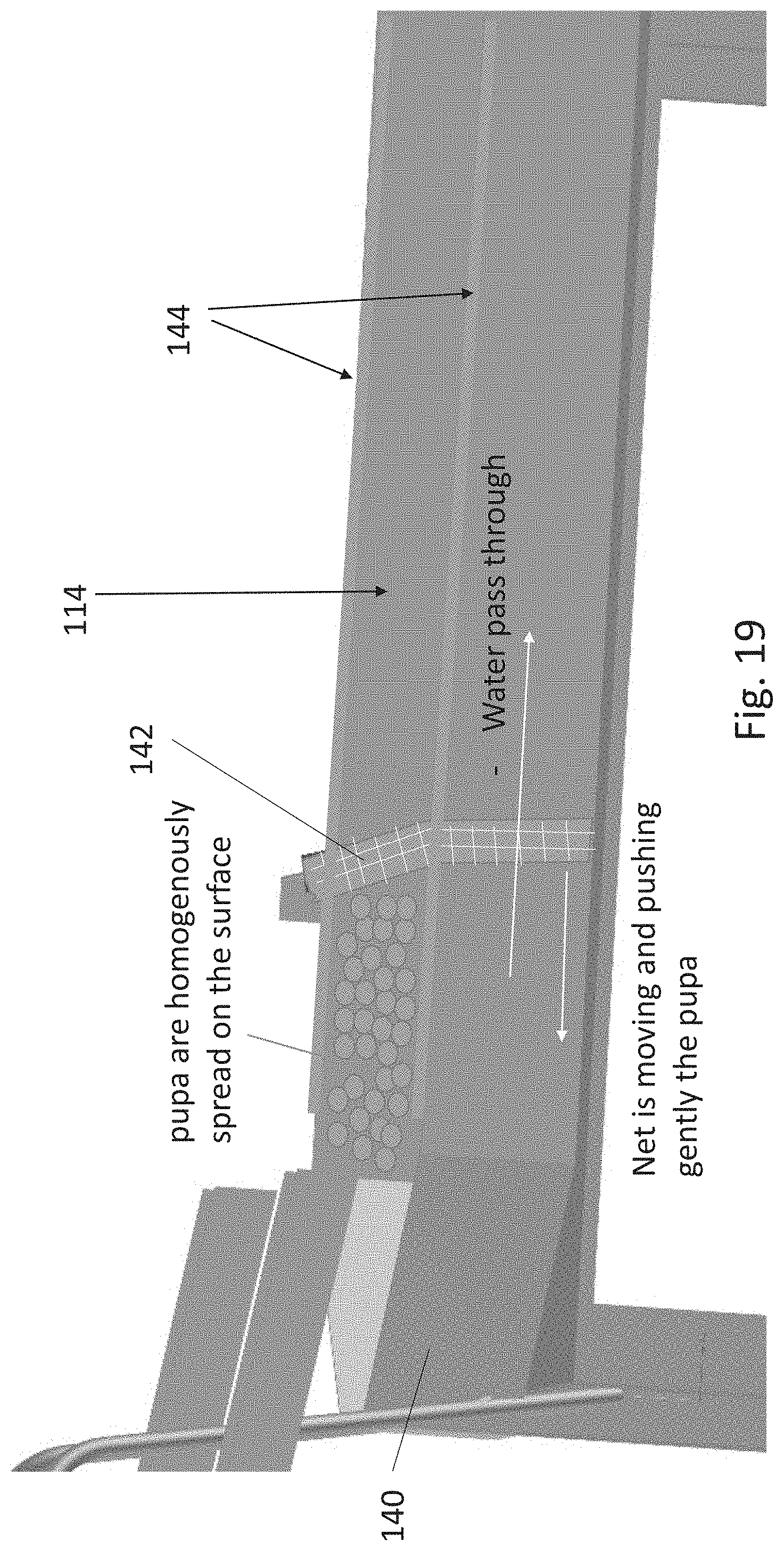
D00016

D00017

D00018

D00019

D00020

D00021

D00022

D00023

D00024

D00025

D00026

D00027

D00028

D00029
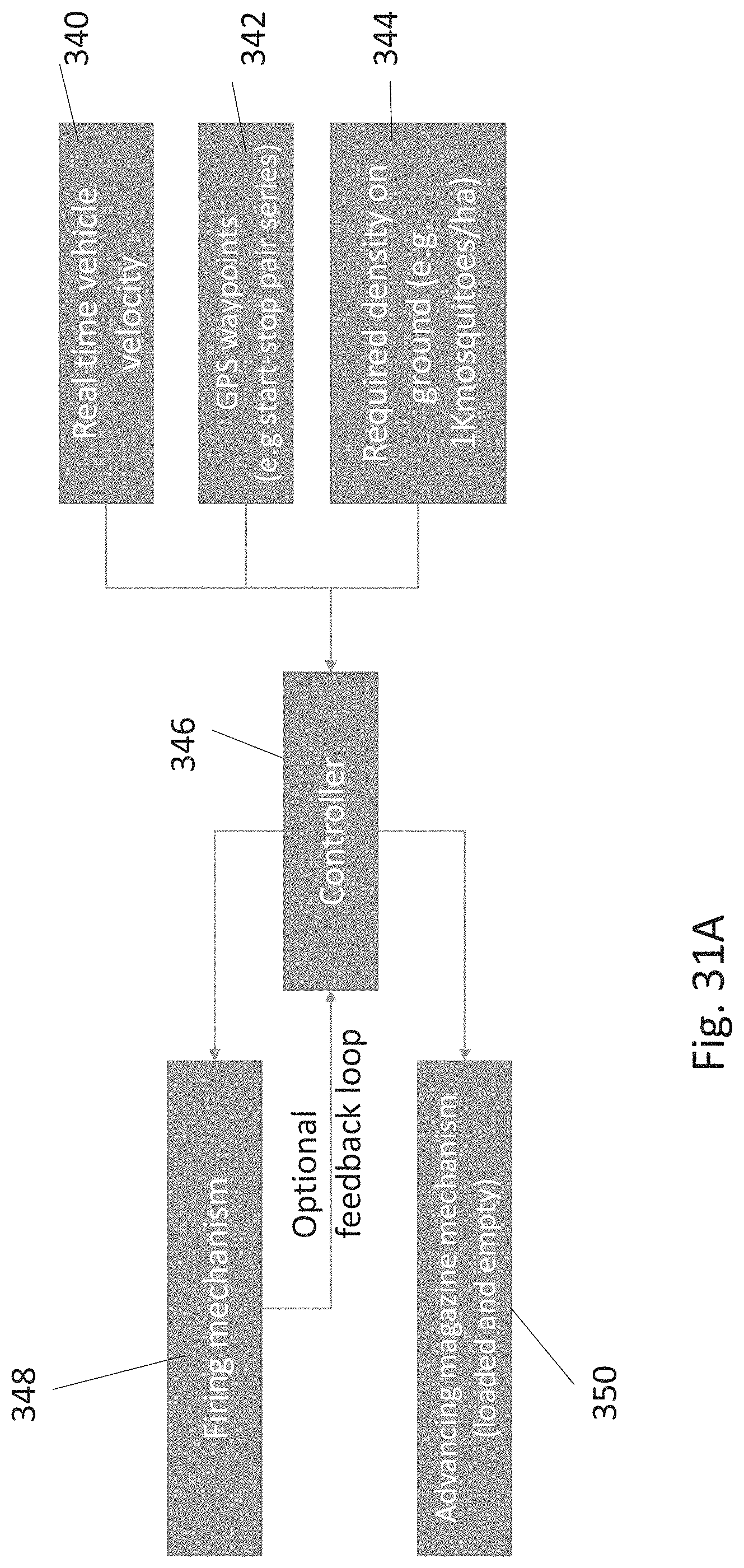
D00030

D00031

D00032

D00033

D00034

D00035
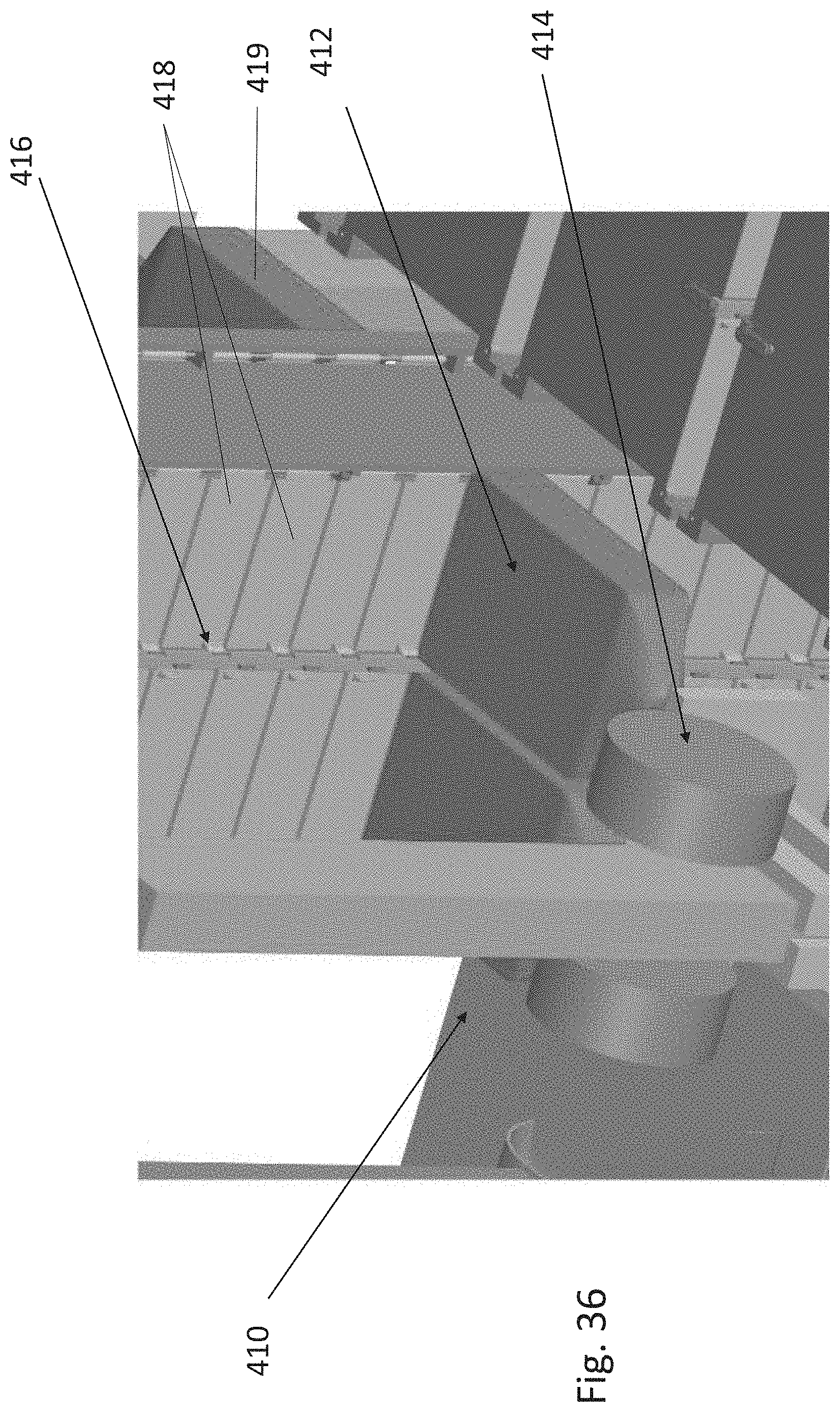
D00036
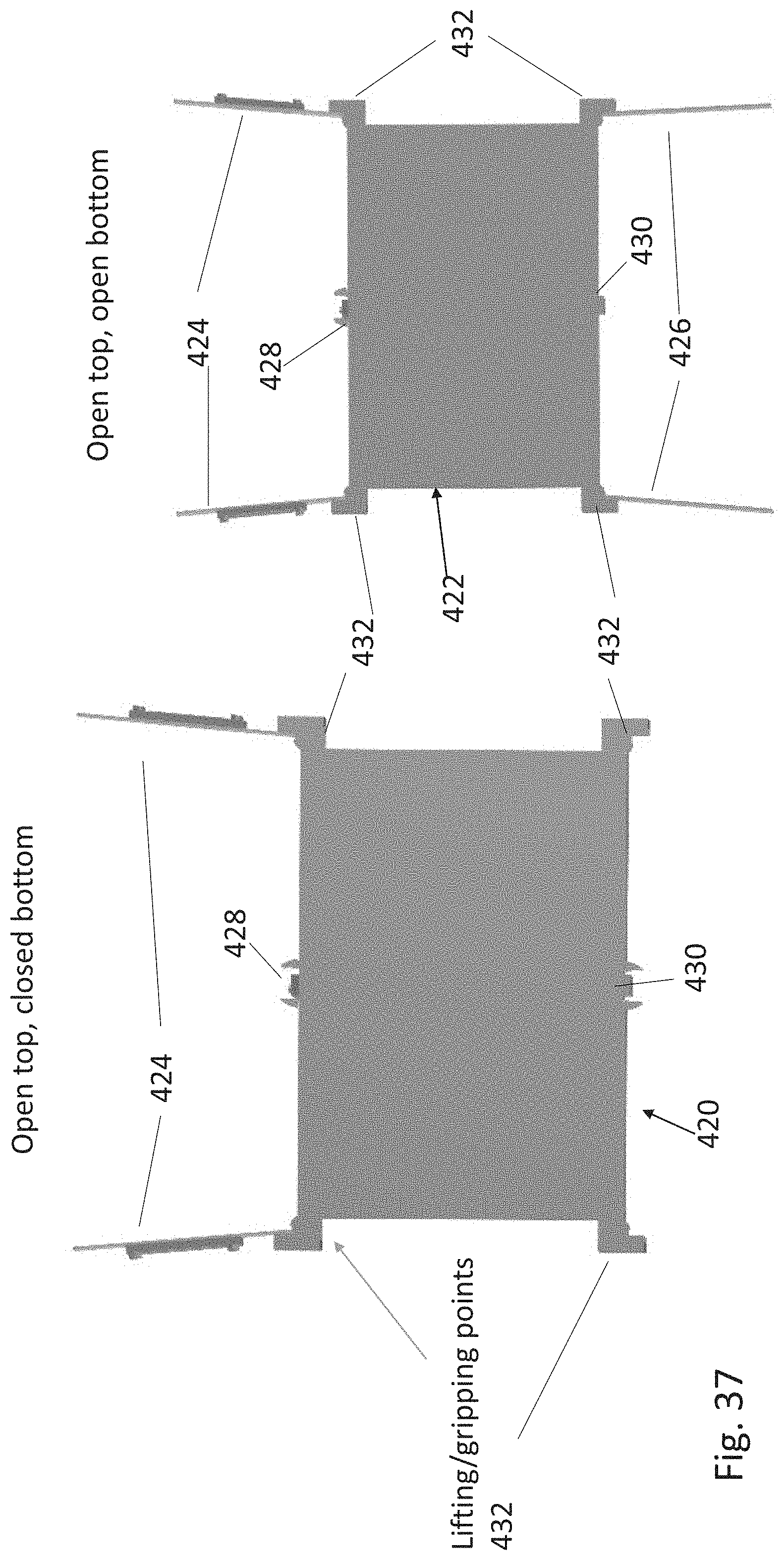
D00037

D00038

D00039

D00040

D00041

D00042

D00043

D00044

D00045

D00046

D00047

D00048

D00049

D00050

D00051

D00052

D00053

D00054

D00055

D00056

D00057

D00058

D00059

D00060

D00061

D00062

D00063

XML
uspto.report is an independent third-party trademark research tool that is not affiliated, endorsed, or sponsored by the United States Patent and Trademark Office (USPTO) or any other governmental organization. The information provided by uspto.report is based on publicly available data at the time of writing and is intended for informational purposes only.
While we strive to provide accurate and up-to-date information, we do not guarantee the accuracy, completeness, reliability, or suitability of the information displayed on this site. The use of this site is at your own risk. Any reliance you place on such information is therefore strictly at your own risk.
All official trademark data, including owner information, should be verified by visiting the official USPTO website at www.uspto.gov. This site is not intended to replace professional legal advice and should not be used as a substitute for consulting with a legal professional who is knowledgeable about trademark law.