Working System And Working Method
HANEDA; Satoshi ; et al.
U.S. patent application number 16/473301 was filed with the patent office on 2020-05-14 for working system and working method. The applicant listed for this patent is HONDA MOTOR CO., LTD.. Invention is credited to Masato FUJIWARA, Satoshi HANEDA, Ryuichi KIMATA, Satoshi ONODERA, Takamasa UDAGAWA, Makoto YAMAMURA.
| Application Number | 20200150647 16/473301 |
| Document ID | / |
| Family ID | 62707279 |
| Filed Date | 2020-05-14 |


| United States Patent Application | 20200150647 |
| Kind Code | A1 |
| HANEDA; Satoshi ; et al. | May 14, 2020 |
WORKING SYSTEM AND WORKING METHOD
Abstract
A working system (100) includes: a working actuator (26) installed on a working machine (1); a camera (21) and a microphone (22) detecting a state of a user changing in accordance with a satisfaction level; a rework determining unit (11) determining whether a rework is needed based on the detected state of the user after a predetermined work is performed by the working machine (1); and an actuator controlling unit (15) controlling the working actuator (26) to perform the rework when it is determined by the rework determining unit (11) that the rework is needed.
| Inventors: | HANEDA; Satoshi; (WAKO-SHI, SAITAMA, JP) ; YAMAMURA; Makoto; (WAKO-SHI, SAITAMA, JP) ; UDAGAWA; Takamasa; (WAKO-SHI, SAITAMA, JP) ; FUJIWARA; Masato; (WAKO-SHI, SAITAMA, JP) ; ONODERA; Satoshi; (MINATO-KU, TOKYO, JP) ; KIMATA; Ryuichi; (MINATO-KU, TOKYO, JP) | ||||||||||
| Applicant: |
|
||||||||||
|---|---|---|---|---|---|---|---|---|---|---|---|
| Family ID: | 62707279 | ||||||||||
| Appl. No.: | 16/473301 | ||||||||||
| Filed: | December 13, 2017 | ||||||||||
| PCT Filed: | December 13, 2017 | ||||||||||
| PCT NO: | PCT/JP2017/044775 | ||||||||||
| 371 Date: | June 25, 2019 |
| Current U.S. Class: | 1/1 |
| Current CPC Class: | G05D 1/0219 20130101; G05D 2201/0208 20130101; A01D 34/76 20130101; G05D 1/0038 20130101; A01D 34/00 20130101; A01D 34/008 20130101; G05D 1/0016 20130101; G05D 1/005 20130101; G05D 1/02 20130101; A01D 2101/00 20130101 |
| International Class: | G05D 1/00 20060101 G05D001/00; A01D 34/00 20060101 A01D034/00; G05D 1/02 20060101 G05D001/02 |
Foreign Application Data
| Date | Code | Application Number |
|---|---|---|
| Dec 27, 2016 | JP | 2016-253720 |
Claims
1-7. (canceled)
8. A working system having a working machine configured to perform a work automatically, comprising: a working actuator installed on the working machine; a user state detecting unit configured to detect a state of a user changing in accordance with a satisfaction level for the work; and an electronic control unit having a microprocessor and a memory, wherein the microprocessor is configured to perform: determining whether a rework is needed based on the state of the user detected by the user state detecting unit after a predetermined work is performed by the working machine; and controlling the working actuator to perform the rework when it is determined that the rework is needed.
9. The working system according to claim 8, wherein the microprocessor is configured to perform determining including estimating the satisfaction level for the work of the user based on the state of the user detected by the user state detecting unit, and determining that the rework is needed when the satisfaction level for the work estimated is equal to or lower than a predetermined value.
10. The working system according to claim 8, wherein the microprocessor is configured to perform determining a work detail based on the state of the user detected by the user state detecting unit, and controlling including controlling the working actuator to perform the rework in accordance with the work detail determined when it is determined that the rework is needed.
11. The working system according to claim 8, wherein the user state detecting unit has at least one of an imaging device, a sound collecting device and a temperature imaging device installed on the working machine.
12. The working system according to claim 8, further comprising a travelling actuator installed on the working machine, wherein the microprocessor is configured to perform controlling including controlling the working actuator and the travelling actuator so that the working machine performs the rework while travelling when it is determined that the rework is needed.
13. The working system according to claim 12, wherein the working machine comprises a lawn mower configured to perform a lawn-mowing work while autonomously traveling in a working area.
14. A working system having a working machine configured to perform a work automatically, comprising: a working actuator installed on the working machine; a user state detecting unit configured to detect a state of a user changing in accordance with a satisfaction level for the work; and an electronic control unit having a microprocessor and a memory, wherein the microprocessor is configured to function as: a rework determining unit configured to determine whether a rework is needed based on the state of the user detected by the user state detecting unit after a predetermined work is performed by the working machine; and an actuator controlling unit configured to control the working actuator to perform the rework when it is determined by the rework determining unit that the rework is needed.
15. The working system according to claim 14, wherein the rework determining unit has a satisfaction level estimating unit configured to estimate the satisfaction level for the work of the user based on the state of the user detected by the user state detecting unit, and configured to determine that the rework is needed when the satisfaction level for the work estimated by the satisfaction level estimating unit is equal to or lower than a predetermined value.
16. The working system according to claim 14, wherein the microprocessor is configured to function as a work detail determining unit configured to determine a work detail based on the state of the user detected by the user state detecting unit, and the actuator controlling unit is configured to control the working actuator to perform the rework in accordance with the work detail determined by the work detail determining unit when it is determined by the rework determining unit that the rework is needed.
17. The working system according to claim 14, wherein the user state detecting unit has at least one of an imaging device, a sound collecting device and a temperature imaging device installed on the working machine.
18. The working system according to claim 14, wherein the microprocessor is configured to function as a travelling actuator installed on the working machine, and the actuator controlling unit is configured to control the working actuator and the travelling actuator so that the working machine performs the rework while travelling when it is determined by the rework determining unit that the rework is needed.
19. The working system according to claim 18, wherein the working machine comprises a lawn mower configured to perform a lawn-mowing work while autonomously traveling in a working area.
20. A working method for performing a work using a working machine configured to perform the work automatically, comprising: detecting a state of a user changing in accordance with a satisfaction level for the work; determining whether a rework after a predetermined work performed by the working machine is needed based on the state of the user detected; and controlling a working actuator installed on the working machine to perform the rework when it is determined that the rework is needed.
21. The working method according to claim 20, wherein the determining whether the rework is needed includes estimating the satisfaction level for the work of the user based on the state of the user detected, and determining that the rework is needed when the satisfaction level for the work estimated is equal to or lower than a predetermined value.
22. The working method according to claim 20, further comprising determining a work detail based on the state of the user detected, wherein the controlling includes controlling the working actuator to perform the rework in accordance with the work detail determined when it is determined that the rework is needed.
23. The working method according to claim 20, wherein the detecting includes at least one of capturing an image of the user, acquiring a speech uttered by the user, and detecting a temperature of the user.
24. The working method according to claim 20, wherein the controlling includes controlling the working actuator and a travelling actuator installed on the working machine so that the working machine performs the rework while travelling when it is determined that the rework is needed.
25. The working method according to claim 24, wherein the working machine comprises a lawn mower configured to perform a lawn-mowing work while autonomously traveling in a working area.
Description
TECHNICAL FIELD
[0001] This invention relates to a working system and a working method having a working machine capable of performing a work automatically.
BACKGROUND ART
[0002] As this type of working machines, there have been known working machines that mow the lawn while autonomously traveling within a working area defined by an area wire (for example, see Patent Literature 1). The working machine described in Patent Literature 1 includes magnetic sensors that detect the strength of a magnetic field generated by a current passing through the area wire, and identifies its own position on the basis of a value detected by the magnetic sensors. Thus, the working machine works while autonomously traveling all over the working area so as not to leave any lawns unmown.
CITATION LIST
Patent Literature
[0003] Patent Literature 1: Japanese Unexamined Patent Publication No. 2016-148937
DISCLOSURE OF INVENTION
Problems to be Solved by the Invention
[0004] The user may not satisfy the state of the working area subjected to lawn mowing by the working machine. In this case, it is necessary to instruct the working machine to perform rework. However, Patent Literature 1 above does not have any description about a method for instructing the working machine to perform rework.
Means for Solving Problem
[0005] An aspect of the present invention is a working system having a working machine configured to perform a work automatically, including: a working actuator installed on the working machine; a user state detecting unit configured to detect a state of a user changing in accordance with a satisfaction level for the work; a rework determining unit configured to determine whether a rework is needed based on the state of the user detected by the user state detecting unit after a predetermined work is performed by the working machine; and an actuator controlling unit configured to control the working actuator to perform the rework when it is determined by the rework determining unit that the rework is needed.
[0006] Another aspect of the present invention is a working method for performing a work using a working machine configured to perform the work automatically, including: detecting a state of a user changing in accordance with a satisfaction level for the work; determining whether a rework after a predetermined work performed by the working machine is needed based on the state of the user detected; and controlling a working actuator installed on the working machine to perform the rework when it is determined that the rework is needed.
Effect of the Invention
[0007] According to the present invention, it becomes possible to easily instruct the working machine to perform rework after the working machine works as necessary.
BRIEF DESCRIPTION OF DRAWINGS
[0008] FIG. 1 is a drawing showing a schematic configuration of a working system according to an embodiment of the present invention;
[0009] FIG. 2A is a block diagram showing a schematic configuration of the working system of FIG. 1;
[0010] FIG. 2B is a block diagram showing a functional configuration of an ECU of FIG. 2A;
[0011] FIG. 3 is a plan view showing an example of a working area for a work by a working machine configuring the working system of FIG. 1;
[0012] FIG. 4 is a flowchart showing an example of a process performed by a CPU of FIG. 2A;
[0013] FIG. 5 is a diagram showing an example of operation of the working system according to the embodiment of the present invention; and
[0014] FIG. 6 is a drawing showing a modification of FIG. 1.
DESCRIPTION OF EMBODIMENT
[0015] Now, a working system according to an embodiment of the present invention will be described with reference to FIGS. 1 to 6. The working system of the present invention can be applied to various types of working machines. In the following, there will be described an example of application of the working system to a lawn mower that is able to mow the lawn while traveling autonomously.
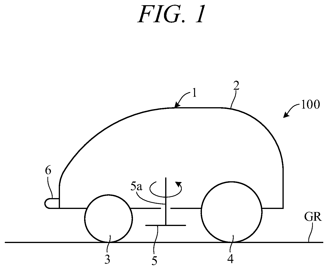
[0016] FIG. 1 is a drawing showing a schematic configuration of the working system 100 according to the embodiment of the present invention, particularly, a side view showing a schematic configuration of a working machine (lawn mower) 1 configuring the working system 100. As shown in FIG. 1, the working machine 1 includes a body 2, a pair of left and right front wheels 3, and a pair of left and right rear wheels 4. The working machine 1 has a weight and size such that any user can carry it with his or her hands. In an example, the working machine 1 has an overall length of about 500 mm, an overall width of about 300 mm, and a height of about 300 mm.
[0017] A disc-shaped, lawn mowing blade 5 supported by a rotating shaft 5a protrudes toward the ground (lawn ground) GR from the bottom of the body 2. The working machine 1 is able to mow the lawn by rotating the blade 5 while traveling on the ground GR. The front end of the body 2 is provided with charging terminals 6 for charging a battery (FIG. 2A) mounted on the body 2.
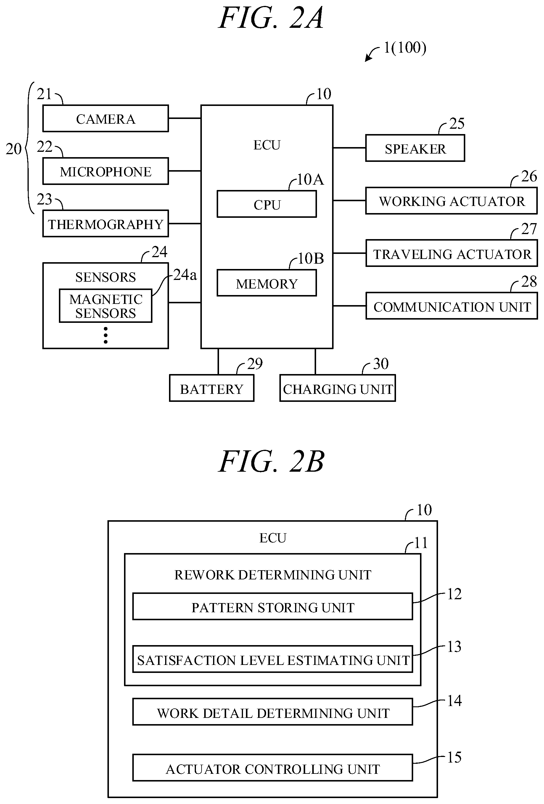
[0018] FIG. 2A is a block diagram showing a schematic configuration of the working machine 1 (working system 100). As shown in FIG. 2A, the working machine 1 includes an electronic control unit (ECU) 10 and also includes a camera 21, a microphone 22, a thermography 23, sensors 24, a speaker 25, a working actuator 26, a traveling actuator 27, a communication unit 28, a battery 29, and a charging unit 30 that are connected to the ECU 10. All these components are mounted on the body 2. The ECU 10 includes a CPU (processor) 10A, a memory 10B such as ROM or RAM, other peripheral circuits, and the like.
[0019] The camera 21, microphone 22, and thermography 23 form a biological information detecting unit 20 that detects biological information of users. Specifically, the camera 21 captures images of the upper-bodies of the users, including the faces, and detects the facial expressions or motions of the users; the microphone 22 acquires speeches uttered by the users, and the speeches acquired by the microphone 22 are recognized by a speech recognition unit (not shown) of the ECU 10; and the thermography 23 detects the surface temperatures of the faces of the users.
[0020] The sensors 24 include a pair of magnetic sensors 24a spaced from each other in the vehicle width direction, and the magnetic sensors 24a detect the magnetic field strength. Although not shown, the sensors 24 also include a Yaw sensor that detects the angular velocity around an axis in the height direction of the working machine 1, a G sensor that detects the acceleration that acts on the working machine 1, an azimuth sensor that detects the azimuth of the working machine 1, a contact sensor that detects whether the working machine 1 has contacted an obstacle, a wheel speed sensor that detects the wheel speed of the left and right rear wheels 4, a GPS sensor that detects the position of the working machine 1, a voltage sensor that detects the remaining voltage of the battery 29, and the like. The speaker 25 outputs a speech to the users. The microphone 22 and speaker 25 allow the working machine 1 to interact with the user.
[0021] The working actuator 26 comprises an electric motor coupled to the rotating shaft 5a. The blade 5 is rotationally driven by driving the working actuator 26. The traveling actuator 27 comprises a pair of electric motors that are disposed inside the left and right rear wheels 4 in the left-right direction and independently drive the left and right rear wheels 4. The working machine 1 can be turned in any direction by making a difference in rotation speed between the left and right rear wheels 4.
[0022] The communication unit 28 includes a transmitting/receiving antenna and a signal processing circuit that processes a signal transmitted or received through the transmitting/receiving antenna. The working machine 1 is able to wirelessly communicate with external devices (e.g., a relay device or server disposed in the same site, mobile terminals carried by the users, etc.) through the communication unit 28. The battery 29 is used as a power supply for supplying power to the electric components of the working machine 1. The charging unit 30 is connected to the charging terminals 6 and battery 29 and stores power supplied from a charging station (FIG. 3) in the battery 29 through the charging terminals 6.
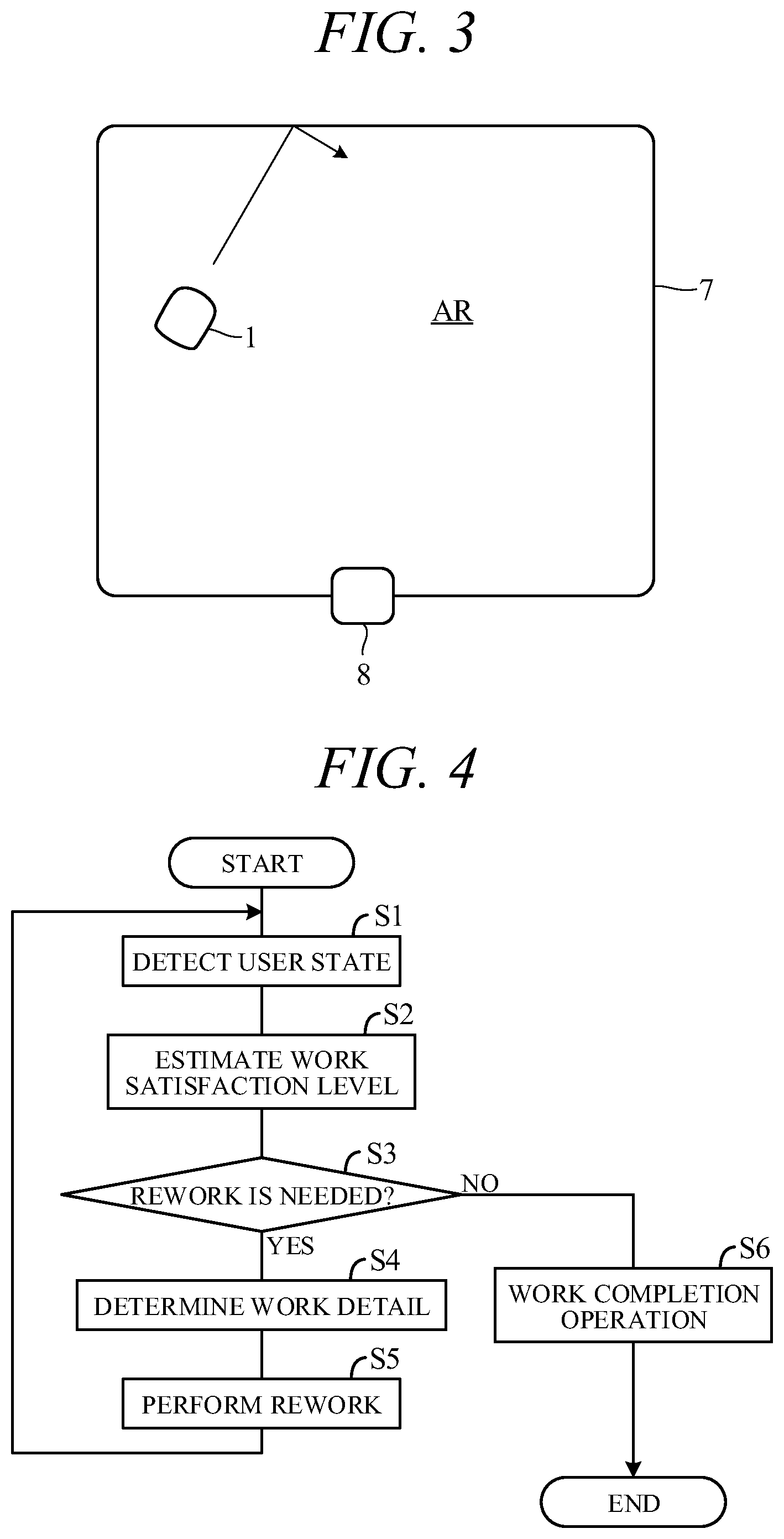
[0023] The working machine 1 thus configured works while autonomously traveling within a predetermined working area. FIG. 3 is a plan view showing an example of a working area AR. The working area AR is defined by an area wire 7 previously installed in the garden (e.g., buried at a predetermined depth from the ground), and the travel range of the working machine 1 is defined by the area wire 7. A magnetic field is generated in the working area AR by passing a current through the area wire 7. The magnetic field strength of the working area AR is detected by the magnetic sensors 24a.
[0024] The magnetic field strength changes in accordance with the distance from the area wire 7. The ECU 10 (CPU 10A) determines whether the working machine 1 has reached the area wire 7, on the basis of signals from the magnetic sensors 24a. If it determines that the working machine 1 has reached the area wire 7, the ECU 10 outputs control signals to the traveling actuator 27 to turn the working machine 1 toward the inside of the working area AR, as shown by an arrow in FIG. 3. As seen above, the ECU 10 outputs control signals to the traveling actuator 27 in accordance with the signals from the magnetic sensors 24a and thus the working machine 1 autonomously travels within the working area AR. At this time, the ECU 10 outputs control signals also to the working actuator 26 and thus the working machine 1 automatically mows the lawn while traveling within the working area AR.
[0025] A charging station 8 for charging the battery 29 is disposed on the area wire 7. If the sensors 24 (e.g., a voltage sensor) detect a voltage shortage of the battery 29 while the working machine 1 works, the ECU 10 outputs control signals to the traveling actuator 27 to return the working machine 1 to the charging station 8, for example, along the area wire 7 and then charges the battery 29. When the charge of the battery 29 is complete, the ECU 10 outputs control signals to the traveling actuator 27 to cause the working machine 1 to leave the charging station 8. The ECU 10 then drives the working actuator 26 to cause the working machine 1 to restart to work.
[0026] As described above, the working area AR is set by installing the area wire 7, and the working machine 1 (ECU 10) works while recognizing the working area AR in accordance with the signals from the magnetic sensors 24a. However, the method for setting and recognizing the working area is not limited to that described above. For example, the ECU 10 may receive a beacon signal through the communication unit 28, and the working machine 1 may work in the working area while recognizing the working area using the received signal. Also, a map of the working area may be previously stored in the memory 10B of the ECU 10, and the working machine 1 may work in the working area while detecting its own position using a GPS sensor or the like. That is, the working area may be set using a working area setting unit other than the area wire 7, and the working machine may work while recognizing the working area using a position detector other than the magnetic sensors.
[0027] When the work of the work machine 1 in the working area AR is complete, the user may not satisfy the work result if some lawns are left unmown or the heights of the lawns are uneven. In this case, it is necessary to instruct the work machine 1 to perform rework. To reduce the load on the user, it is preferred to omit the time and effort for the user to instruct the work machine 1 to perform rework by making troublesome settings and to configure the work machine 1 such that the working machine 1 automatically performs rework in accordance with the work satisfaction level of the user. In view of these points, in the present embodiment, the work machine 1 is configured as follows.
[0028] FIG. 2B is a block diagram showing the functional configuration of the ECU 10. As shown in FIG. 2B, the ECU 10 includes a rework determining unit 11, a work detail determining unit 14, and an actuator controlling unit 15. The rework determining unit 11 includes a pattern storing unit 12 and a satisfaction level estimating unit 13. Among these, the satisfaction level estimating unit 13, work detail determining unit 14, and actuator controlling unit 15 are functions performed by the CPU 10A, and the pattern storing unit 12 is a function performed by the memory 10B.
[0029] The pattern storing unit 12 previously stores data corresponding to the patterns of facial expressions, motions, speeches and facial temperature having correlations with the work satisfaction levels of the user, that is, data corresponding to the facial expression patterns, motion patterns, speech patterns, and facial temperature patterns.
[0030] The facial expression patterns include facial expression patterns expected to occur when the work satisfaction level is high (e.g., facial expressions of joy) and facial expression patterns expected to occur when the work satisfaction level is low (e.g., facial expressions of anger). The pattern storing unit 12 stores image data corresponding to these facial expression patterns. Note that facial expressions of joy or anger are characterized by the angle of mouth, or look of eyes.
[0031] The motion patterns include motion patterns expected to occur when the work satisfaction level is high (e.g., motions, such as a nod of the head and a raise of the thumb) and motion patterns expected to occur when the work satisfaction level is low (e.g., motions, such as a shake of the head and a touch of the user on the lawn with a hand). The pattern storing unit 12 stores image data corresponding to these motion patterns.
[0032] The speech patterns include speech patterns expected to occur when the work satisfaction level is high (e.g., speeches of "OK" and the like) and speech patterns expected to occur when the work satisfaction level is low (e.g., speeches of "try again" and the like). The pattern storing unit 12 stores speech data corresponding to these speech patterns.
[0033] The facial temperature patterns include facial temperature patterns expected to occur when the work satisfaction level is high (e.g., facial temperature distributions in which the average or maximum facial temperature is a predetermined temperature or lower) and facial temperature patterns expected to occur when the work satisfaction level is low (e.g., facial temperature distributions in which the average or maximum facial temperature a predetermined temperature or higher). The pattern storing unit 12 stores temperature data corresponding to these facial temperature patterns.
[0034] The above patterns are previously given points corresponding to the work satisfaction levels. Specifically, a pattern having a high work satisfaction level is given a point of +1, and a pattern having a low work satisfaction level is given a point of -1. A pattern having a higher work satisfaction level may be given a greater positive point, and a pattern having a lower work satisfaction level may be given a smaller negative point (with a greater absolute value). As seen above, the pattern storing unit 12 stores the multiple patterns indicating user states corresponding to the work satisfaction levels (hereafter referred to as "work satisfaction level correspondence patterns") with the points.
[0035] The pattern storing unit 12 also stores multiple patterns corresponding to details of rework (referred to as "work details correspondence patterns"). Specifically, the pattern storing unit 12 stores image data corresponding to motion patterns indicating areas in which rework should be performed, for example, image data corresponding to motions in which the user points a finger at a particular direction, such as a direction toward the east, west, south, or north or a forward, rear, left, or right direction, and motions indicating the entire working area. The pattern storing unit 12 also stores speech data corresponding to speech patterns indicating areas in which rework should be performed, for example, speech data corresponding to speeches indicating a particular direction, such as a direction toward the east, west, south, or north or a forward, rear, left, or right direction, and speeches indicating the entire working area, such as "do it all again". The pattern storing unit 12 also stores image data corresponding to motion patterns indicating an instruction to travel so as to automatically follow the user (e.g., a beckoning motion) and speech data corresponding to speech patterns indicating an automatic follow travel instruction (e.g., speeches of "follow me" and the like).
[0036] The satisfaction level estimating unit 13 estimates the work satisfaction level of the user about a work result obtained by performing the lawn-mowing work once, on the basis of a signal from the biological information detector 20. More specifically, the satisfaction level estimating unit 13 compares the facial expression, motion, speech and facial temperature of the user detected by the biological information detector 20 with the patterns of the facial expression, motion, speech and facial temperature of the user (work satisfaction level correspondence patterns) stored in the pattern storing unit 12 and identifies a work satisfaction level correspondence pattern that the states of the user match. The satisfaction level estimating unit 13 then converts the work satisfaction level into a numerical value using the point of the identified work satisfaction level correspondence pattern. If the user states match multiple work satisfaction level correspondence patterns, the satisfaction level estimating unit 13 calculates the work satisfaction level by summing up the points of the work satisfaction level correspondence patterns.
[0037] The work satisfaction level corresponds to the emotion of the user. For this reason, the satisfaction level estimating unit 13 may estimate the work satisfaction level by estimating the emotion of the user. For example, the satisfaction level estimating unit 13 may categorize the emotions of the user into eight basic emotions (anticipation, joy, acceptance, fear, surprise, sadness, disgust, and anger) and application emotions consisting of adjacent pairs of these emotions using the wheel of emotions of Plutchik, determine an emotion in the wheel of emotions that the emotion of the user matches, on the basis of signals from the camera 21 and microphone 22, and estimate the work satisfaction level from the determined emotion.
[0038] The rework determining unit 11 determines whether rework is needed, in accordance with the work satisfaction level estimated by the satisfaction level estimating unit 13. For example, if the estimated work satisfaction level is equal to or lower than a predetermined value (for example, -1), the rework determining unit 11 determines that rework is needed.
[0039] The work detail determining unit 14 determines details of rework on the basis of a signal received from the biological information detector 20. More specifically, the work detail determining unit 14 compares the motion or speech of the user detected by the biological information detector 20 with the patterns of the motion or speech of the user (work satisfaction level correspondence patterns) stored in the pattern storing unit 12, identifies a work details correspondence pattern that the user states match, and determines the identified work details correspondence pattern as the work details of the work machine 1.
[0040] The actuator controlling unit 15 outputs control signals to the working actuator 26 and traveling actuator 27 to control the operation of the work machine 1 so that the work machine 1 mows the lawn while autonomously traveling within the working area AR. Also, once the work is complete, the actuator controlling unit 15 controls the travel operation of the work machine 1 so that the work machine 1 moves to a position in which the biological information detector 20 can detect the user states. Then, if the rework determining unit 11 determines that rework is needed, the actuator controlling unit 15 outputs control signals to the working actuator 26 and traveling actuator 27 so that the work machine 1 performs the work determined by the work detail determining unit 14. On the other hand, if the rework determining unit 11 determines that rework is not needed, the actuator controlling unit 15 controls the operation of the work machine 1 so that the work machine 1 performs a predetermined work completion operation, such as return to the charge station 8 and the start of a charge.
[0041] FIG. 4 is a flowchart showing an example of a process performed by the CPU 10A in accordance with a previously stored program. The process shown in this flowchart is started, for example, after the work machine 1 performs predetermined work while autonomously traveling.
[0042] First, in step S1, the biological information detector 20 detects the states of the user, that is, the facial expression, motion, speech, and facial temperature of the user and reads detection signals thereof. Then, in step S2, the satisfaction level estimating unit 13 estimates the work satisfaction level of the user on the basis of the detection signals in step S1. Then, in step S3, the rework determining unit 11 determines whether rework is needed, that is, whether the estimated work satisfaction level is equal to or lower than the predetermined value.
[0043] If the determination in step S3 is YES, the process proceeds to step S4, and the work detail determining unit 14 determines details of the rework on the basis of the detection signals in step S1. Then, in step S5, the actuator controlling unit 15 outputs control signals to the working actuator 26 and traveling actuator 27 so that the work machine 1 performs rework corresponding to the work details determined in step S4. When the rework is completed, the process returns to step S1, and a similar process is repeated.
[0044] If it is determined in step S3 that rework is not needed, the process proceeds to step S6. In step S6, the actuator controlling unit 15 performs a predetermined work completion operation, for example, instructs the work machine 1 to return to the charge station 8, thereby ending the process.
[0045] The operation of the working system 100 according to the present embodiment will be described more specifically. FIG. 5 is a plan view showing an example of the operation of the working system 100. When the work machine 1 completes the lawn-mowing work in the working area AR, it approaches a user 200 and detects the states of the user 200 using the biological information detector 20, such as the camera 21 and microphone 22, as shown by a portion A in FIG. 5 (step S1). Note that the user 200 may approach the work machine 1.
[0046] If the work satisfaction level of the user 200 becomes equal to or lower than the predetermined value due to the presence of unmown lawns, the uneven heights of the lawns, or the like, the work machine 1 determines that rework is needed and determines work details on the basis of the motion and speech of the user 200 (step S3.fwdarw.step S4). The work machine 1 then performs rework corresponding to the work details (step S5). For example, if the user 200 points a finger at a predetermined working area AR1 or specifies the predetermined working area AR1 with a speech, the work machine 1 moves to the working area AR1 (a portion B in FIG. 5) while autonomously traveling, as shown by an arrow AW1 in FIG. 5, and performs rework in the working area AR1.
[0047] On the other hand, if the user 200 instructs the work machine 1 to travel so as to automatically follow the user, the work machine 1 follows the movement of the user 200 shown by a dotted arrow AW2 in FIG. 5 and moves to a predetermined working area AR2 (a portion C in FIG. 5), as shown by an arrow AW3 in FIG. 5. Then, when the user 200 instructs the work machine 1 to work in the working area AR2, the work machine 1 performs rework in the working area AR2. If the user 200 instructs the work machine 1 with motion or speech to perform rework all over the working area AR, the work machine 1 performs rework all over the working area AR.
[0048] When the rework is completed, the work machine 1 detects the user states again and estimates the work satisfaction level (step S5.fwdarw.step S1.fwdarw.step S2). If the work satisfaction level is equal to or lower than the predetermined value, the work machine 1 performs rework again. If the work satisfaction level exceeds the predetermined value, the work machine 1 performs a work completion operation, thereby ending the work (step S3.fwdarw.step S6).
[0049] The present embodiment can produce the following advantageous effects:
[0050] (1) The working system 100 having the work machine 1 that works automatically includes the working actuator 26 disposed on the work machine 1, the biological information detector 20 (camera 21, microphone 22, and thermography 23) that detects the user states that change in accordance with the work satisfaction level, the rework determining unit 11 that determines whether rework is needed, on the basis of the user states detected by the biological information detector 20 after the work machine 1 performs predetermined work (lawn mowing while traveling autonomously), and the actuator controlling unit 15 that if the rework determining unit 11 determines that rework is needed, controls the working actuator 26 so that the work machine 1 performs rework (FIGS. 2A, 2B).
[0051] As seen above, in the working system 100 according to the present embodiment, the work machine 1 itself determines whether rework is needed, on the basis of the user states detected by the biological information detector 20 after the lawn mowing is performed once, and automatically performs rework in accordance with the determination result. This eliminates the need for the user to separately perform a troublesome operation to instruct the work machine 1 to perform rework, enabling to easily instruct the work machine 1 to perform rework as necessary.
[0052] (2) The rework determining unit 11 includes the satisfaction level estimating unit 13 that estimates the work satisfaction level of the user on the basis of the user states detected by the biological information detector 20 (FIG. 2B) and, if the work satisfaction level estimated by the satisfaction level estimating unit 13 is equal to or lower than the predetermined value, determines that rework is needed. As seen above, the working system 100 is configured to perform rework in accordance with the work satisfaction level of the user. Thus, if the user is not satisfied with the work result, the working system 100 is able to cause the work machine 1 to automatically perform rework and thus to improve the work satisfaction level of the user.
[0053] (3) The working system 100 also includes the work detail determining unit 14 that determines work details on the basis of the user states detected by the biological information detector 20 (FIG. 2B). If the rework determining unit 11 determines that rework is needed, the actuator controlling unit 15 controls the working actuator 26 to perform rework corresponding to the work details determined by the work detail determining unit 14. This configuration enables to instruct the work machine 1 to perform rework, for example, only in the particular working areas AR1, AR2 of the working area AR, that is, enables the work machine 1 to efficiently perform rework.
[0054] (4) The camera 21, microphone 22, and thermography 23 serving as the biological information detector 20 are disposed on the working machine 1 (FIG. 2A). Thus, the working system 100 is able to recognize the facial expression, motion, speech, and facial temperature of the user. As a result, the working system 100 is able to favorably estimate the work satisfaction level of the user and to properly determine whether rework is needed.
[0055] (5) The working system 100 also includes the traveling actuator 27 disposed on the work machine 1 (FIG. 2A). If the rework determining unit 11 determines that rework is needed, the actuator controlling unit 15 controls the working actuator 26 and traveling actuator 27 so that the work machine 1 performs rework while traveling. Since the work machine 1 is configured to be able to move as described above, the working system 100 is able to cause the work machine 1 to automatically work all over the working area.
[0056] (6) The working machine 1 configuring the working system 100 comprises a lawn mower that mows the lawn while autonomously traveling within the working area AR (FIG. 1). The work machine 1 thus configured may, for example, leave some lawns unmown, and there is a high probability that rework will be needed. For this reason, it is very useful to apply the working system 100 according to the present embodiment.
[0057] (7) A working method using the work machine 1 that automatically performs a work includes detecting the user states that change in accordance with the work satisfaction level (step S1), determining whether rework is needed after the work machine 1 performs predetermined work, on the basis of the detected user states (step S3), and if it is determined that rework is needed, controlling the working actuator 26 disposed on the work machine 1 so that the work machine 1 performs rework (step S5). This method enables to easily instruct the work machine 1 to perform rework as necessary.
[0058] The above embodiment can be modified into various forms, and modifications will be described below. FIG. 6 is a diagram showing a working system 100A as a modification of FIG. 1. In FIG. 6, a work machine 1 and a server 101 are configured to be able to wirelessly communicate with each other through a communication unit. According to this configuration, the ECU 10 of the working machine 1 is able to obtain data from the server 101 as necessary. Accordingly, a part of the ECU 10 (e.g., a pattern storing unit 12) can be disposed in the server 101.
[0059] While, in the above embodiment, the camera 21 as an imaging device, the microphone 22 as a sound collector, and the thermography 23 as a temperature imaging device detect the user states that change in accordance with the work satisfaction level, a user state detector is not limited to this configuration. For example, not all of the imaging device, sound collector, and temperature imaging device but at least one of these may detect the state of the user, that is, the facial expression, motion, speech, or the like of the user. The user state detector may be disposed on an entity (e.g., the wall of a building) other than the working machine.
[0060] While, in the above embodiment, the satisfaction level estimating unit 13 estimates the work satisfaction level of the user by converting the work satisfaction level into a numerical value on the basis of the user states detected by the biological information detector 20, a satisfaction level estimating unit is not limited to the above configuration and, for example, may simply estimate whether the work satisfaction level has been obtained. While, in the above embodiment, the work detail determining unit 14 determines the work details on the basis of the user states detected by the biological information detector 20, a work detail determining unit is not limited to the above configuration and, for example, may determine the work details in accordance with the work satisfaction level estimated by the work satisfaction level estimating unit.
[0061] While, in the above embodiment, the rework determining unit 11 determines whether rework is needed, on the basis of the user states detected by the camera 21, microphone 22, and the like after the work machine 1 mows the lawn, a rework determining unit is not limited to this configuration. For example, it may determine whether rework is needed, by asking the user a question of "Is rework needed?" or the like using speech output from the speaker 25 and recognizing a user response to this question as a speech. If the user is having a conversation with someone, the rework determining unit may determine whether rework is needed, from details of the conversation. Weather detection sensors, such as a sunlight sensor, a temperature/humidity sensor, and a rain sensor, may be disposed on the working machine, and the rework determining unit may determine whether rework is needed, considering information from these sensors.
[0062] Although the rework determining unit 11 determines whether rework is needed and the work machine 1 performs rework, the work satisfaction level of the user may not be improved. Such cases include a case in which a blade 5 as a working device is damaged. In this case, the work machine 1 may determine that some defect exists in itself and make contact with a dealer through the communication unit 28 to request the dealer to maintain the work machine 1. That is, the rework determining unit may determine not only whether rework is needed, but also whether a maintenance request is needed, or the like. Also, the rework determining unit may determine whether rework is needed, on the basis of whether a predetermined state of the user has been detected, regardless of the work satisfaction level. In this case, the work satisfaction level estimating unit may be omitted. Details of rework may be fixed. For example, rework may be always performed all over the working area AR. In this case, the work detail determining unit may be omitted.
[0063] While, in the above embodiment, if the rework determining unit 11 determines that rework is needed, the actuator controlling unit 15 controls the working actuator 26 and traveling actuator 27 so that the work machine 1 performs rework, an actuator controlling unit is not limited to the above configuration and, for example, may control at least the working actuator so that the work machine performs rework.
[0064] While, in the above embodiment, the moving lawn mower is used as the work machine 1, a moving working machine (e.g., a working machine used indoors) other than a lawn mower, or a fixed working machine (e.g., a sprinkler) may be used as a working machine. Accordingly, the traveling actuator and working actuator disposed on the working machine are not limited to the above configuration.
[0065] The above description is only an example, and the present invention is not limited to the above embodiment and modifications, unless impairing features of the present invention. The above embodiment can be combined as desired with one or more of the above modifications. The modifications can also be combined with one another.
REFERENCE SIGNS LIST
[0066] 1 working machine, 11 rework determining unit, 13 satisfaction level estimating unit, 14 work detail determining unit, 15 actuator controlling unit, 20 biological information detecting unit, 21 camera, 22 microphone, 23 thermography, 26 working actuator, 27 traveling actuator, 100, 100A working system
* * * * *
D00000
D00001
D00002
D00003
D00004
XML
uspto.report is an independent third-party trademark research tool that is not affiliated, endorsed, or sponsored by the United States Patent and Trademark Office (USPTO) or any other governmental organization. The information provided by uspto.report is based on publicly available data at the time of writing and is intended for informational purposes only.
While we strive to provide accurate and up-to-date information, we do not guarantee the accuracy, completeness, reliability, or suitability of the information displayed on this site. The use of this site is at your own risk. Any reliance you place on such information is therefore strictly at your own risk.
All official trademark data, including owner information, should be verified by visiting the official USPTO website at www.uspto.gov. This site is not intended to replace professional legal advice and should not be used as a substitute for consulting with a legal professional who is knowledgeable about trademark law.