Optical Lens System And Vehicle Camera
WEI; WENZHE ; et al.
U.S. patent application number 16/744155 was filed with the patent office on 2020-05-14 for optical lens system and vehicle camera. The applicant listed for this patent is JIANGXI LIANCHUANG ELECTRONIC CO., LTD.. Invention is credited to YUMIN BAO, WEIJIAN CHEN, XUMING LIU, KEMIN WANG, WENZHE WEI, JIYONG ZENG.
| Application Number | 20200150386 16/744155 |
| Document ID | / |
| Family ID | 64421532 |
| Filed Date | 2020-05-14 |


View All Diagrams
| United States Patent Application | 20200150386 |
| Kind Code | A1 |
| WEI; WENZHE ; et al. | May 14, 2020 |
OPTICAL LENS SYSTEM AND VEHICLE CAMERA
Abstract
The disclosure provides an optical lens system and a vehicle camera. From an object side to an imaging surface, the optical lens system sequentially includes a first lens having a negative refractive power; a second lens having a positive refractive power; a third lens having a positive refractive power; a fourth lens having a positive refractive power; a fifth lens having a negative refractive power, the fourth lens and the fifth lens constituting a cemented lens; a sixth lens having a positive refractive power; a seventh lens with a negative refractive power; a stop disposed between the first lens and the third lens. The lens of the present disclosure not only has thermal stability, but also has extremely high resolution for the objects that emit or reflect monochromatic lights of different wavelengths, so as to meet the requirements of the driverless vehicle system on the lens.
| Inventors: | WEI; WENZHE; (NANCHANG, CN) ; BAO; YUMIN; (NANCHANG, CN) ; CHEN; WEIJIAN; (NANCHANG, CN) ; LIU; XUMING; (NANCHANG, CN) ; ZENG; JIYONG; (NANCHANG, CN) ; WANG; KEMIN; (NANCHANG, CN) | ||||||||||
| Applicant: |
|
||||||||||
|---|---|---|---|---|---|---|---|---|---|---|---|
| Family ID: | 64421532 | ||||||||||
| Appl. No.: | 16/744155 | ||||||||||
| Filed: | January 15, 2020 |
Related U.S. Patent Documents
| Application Number | Filing Date | Patent Number | ||
|---|---|---|---|---|
| PCT/CN2019/085184 | Apr 30, 2019 | |||
| 16744155 | ||||
| Current U.S. Class: | 1/1 |
| Current CPC Class: | H04N 5/2257 20130101; G02B 13/0045 20130101; G02B 13/006 20130101; G02B 9/64 20130101; G02B 9/60 20130101 |
| International Class: | G02B 9/64 20060101 G02B009/64; H04N 5/225 20060101 H04N005/225 |
Foreign Application Data
| Date | Code | Application Number |
|---|---|---|
| Jun 14, 2018 | CN | 201810614191.9 |
Claims
1. An optical lens system, from an object side to an imaging surface thereof, the optical lens system sequentially comprising: a first lens having a negative refractive power and a concave surface facing the object side: a second lens having a positive refractive power and two convex surfaces; a third lens having a positive refractive power and a convex surface facing the object side; a fourth lens having a positive refractive power and two convex surfaces; a fifth lens having a negative refractive power and two concave surfaces, the fourth lens and the fifth lens constituting a cemented lens; a sixth lens having a positive refractive power, a convex surface facing the object side and a concave surface facing the imaging surface; a seventh lens having a negative refractive power and a concave surface facing the imaging surface; wherein the optical lens system further comprises a stop disposed between the first lens and the third lens, the first lens, the fourth lens and the fifth lens are glass spherical lenses, and the seventh lens is a glass aspheric lens.
2. The optical lens system as claimed in claim 1, wherein the third lens and the fourth lens satisfy the following expression: (dn/dt).sub.3+(dn/dt).sub.4<-2.times.10.sup.6/.degree. C.; where (dn/dt).sub.3 represents a temperature coefficient of refractive index of the third lens, (dn/dt).sub.4 represents a temperature coefficient of refractive index of the fourth lens.
3. The optical lens system as claimed in claim 1, wherein the third lens and the fourth lens satisfy the following expressions: Vd.sub.3+Vd.sub.4>150; .DELTA.Pg,F3+.DELTA.Pg,F4>0.005: where Vd.sub.3 represents the abbe number of the third lens, Vd.sub.4 represents the abbe number of the fourth lens, .DELTA.Pg,F3 represents a deviation of relative partial dispersion from the abbe empirical formula of the third lens, .DELTA.Pg,F4 represents a deviation of relative partial dispersion from the abbe empirical formula of the fourth lens.
4. The optical lens system as claimed in claim 1, wherein the optical lens system satisfies the following expressions: 0.5<.parallel.f.sub.52|-t.sub.52|<13; 0.1<.parallel.f.sub.61|-t.sub.61|<10; where f.sub.52 represents a focal length of an image side surface of the fifth lens, f.sub.61 represents a focal length of an object side surface of the sixth lens, t.sub.52 represents a distance from a vertex of an image side surface of the fifth lens to the imaging surface of the optical lens system, t.sub.61 is a distance from a vertex of an object side surface of the sixth lens to the imaging surface of the optical lens system.
5. The optical lens system as claimed in claim 1, wherein the optical lens system satisfies the following expression: 0.2<IH/.theta.<0.3; where .theta. represents half field angle of the optical lens system, and IH represents an image height when the half field angle is 0.
6. The optical lens system as claimed in claim 1, wherein the third lens and the fourth lens satisfy the following expression: 40<.phi..sub.3+.phi..sub.4<75; where .phi..sub.3 represents a refractive power of the third lens, .phi..sub.4 represents a refractive power of the fourth lens.
7. The optical lens system as claimed in claim 1, wherein the optical lens system satisfies the following expression: 0.5<f.sub.1/r.sub.1<3; where f.sub.1 represents a focal length of the first lens, r.sub.1 represents a radius of curvature of an object side surface of the first lens.
8. The optical lens system as claimed in claim 1, wherein the optical lens system satisfies the following expression: 5<CT.sub.2+CT.sub.3<13; where CT.sub.2 represents a center thickness of the second lens, and CT.sub.3 represents a center thickness of the third lens.
9. The optical lens system as claimed in claim 1, wherein the optical lens system satisfies the following expression: 1<f.sub.3/r.sub.5<4; where f.sub.3 represents a focal length of the third lens, r.sub.5 represents a radius of curvature of an object side surface of the third lens.
10. The optical lens system as claimed in claim 1, wherein the optical lens system satisfies the following expression: -13<f.sub.7/r.sub.13<0; where f.sub.7 represents a focal length of the seventh lens, and r.sub.13 represents a radius of the curvature of an image side surface of the seventh lens.
11. A vehicle camera, comprising an image sensor and an optical lens system, the image sensor being configured to convert optical images formed by the optical lens system into electrical signals; from an object side to an imaging surface, the optical lens system sequentially comprising: a first lens with a negative refractive power, comprising a concave surface facing the object side; a second lens with a positive refractive power, comprising two convex surfaces respectively facing the object side and the imaging surface; a third lens with a positive refractive power, comprising a convex surface facing the object side; an achromatic doublet lens comprising a fourth lens with a positive refractive power and a fifth lens with a negative refractive power, an image side surface of the fourth lens being matched with and bonded to an object side surface of the fifth lens; a sixth lens with a positive refractive power, comprising a convex surface facing the object side and a concave surface facing the imaging surface; a seventh lens with a negative refractive power, comprising a concave surface facing the imaging surface; wherein the optical lens system further comprises a stop disposed between the first lens and the third lens; the first lens, the fourth lens and the fifth lens are glass spherical lenses, and the seventh lens is a glass aspheric lens.
12. The vehicle camera as claimed in claim 11, wherein the third lens and the fourth lens satisfy the following expression: (dn/dt).sub.3+(dn/dt).sub.4<-2.times.10.sup.-6/.degree. C.; where (dn/dt).sub.3 represents a temperature coefficient of refractive index of the third lens, (dn/dt).sub.4 represents a temperature coefficient of refractive index of the fourth lens.
13. The vehicle camera as claimed in claim 11, wherein the third lens and the fourth lens satisfy the following expressions: Vd.sub.3+Vd.sub.4>150; .DELTA.Pg,F3+.DELTA.Pg,F4>0.005; where Vd.sub.3 represents the abbe number of the third lens, Vd.sub.4 represents the abbe number of the fourth lens, .DELTA.Pg,F3 represents a deviation of relative partial dispersion from the abbe empirical formula of the third lens, .DELTA.Pg,F4 represents a deviation of relative partial dispersion from the abbe empirical formula of the fourth lens.
14. The vehicle camera as claimed in claim 11, wherein the optical lens system satisfies the following expressions: 0.5<.parallel.f.sub.52|-t.sub.52|<13: 0.1<.parallel.f.sub.61|-t.sub.61|<10: where f.sub.52 represents a focal length of an image side surface of the fifth lens, f.sub.61 represents a focal length of an object side surface of the sixth lens, t.sub.52 represents a distance from a vertex of an image side surface of the fifth lens to the imaging surface of the optical lens system, t.sub.61 is a distance from a vertex of an object side surface of the sixth lens to the imaging surface of the optical lens system.
15. The vehicle camera as claimed in claim 11, wherein the optical lens system satisfies the following expression: 0.2<IH/.theta.<0.3; where .theta. represents half field angle of the optical lens system, and IH represents an image height when the half field angle is .theta..
16. The vehicle camera as claimed in claim 11, wherein the third lens and the fourth lens satisfy the following expression: 40<.phi..sub.3+.phi..sub.4<75; where .phi..sub.3 represents a refractive power of the third lens, .phi..sub.4 represents a refractive power of the fourth lens.
17. The vehicle camera as claimed in claim 11, wherein the optical lens system satisfies the following expression: 0.5<f.sub.1/r.sub.1<3; 1<f.sub.3/r.sub.5<4; -13<f.sub.7/r.sub.13<0; 5<CT.sub.2+CT.sub.3<13; where f.sub.1 represents a focal length of the first lens, r.sub.1 represents a radius of curvature of an object side surface of the first lens; f.sub.3 represents a focal length of the third lens, r.sub.5 represents a radius of curvature of an object side surface of the third lens; f.sub.7 represents a focal length of the seventh lens, and r.sub.13 represents a radius of the curvature of an image side surface of the seventh lens; CT.sub.2 represents a center thickness of the second lens, and CT.sub.3 represents a center thickness of the third lens.
18. An optical lens system, from an object side to an imaging surface thereof, sequentially comprising: a first lens with a negative refractive power, an object side surface of the first lens being concave; a second lens with a positive refractive power, an object side surface and an image side surface of the second lens each being convex; a third lens with a positive refractive power, an object side surface of the third lens being convex; an achromatic doublet lens, comprising a fourth lens with a positive refractive power and a fifth lens with a negative refractive power, an object side surface and an image side surface of the fourth lens each being convex, an object side surface and an image side surface of the fifth lens each being concave; a sixth lens with a positive refractive power, an object side surface of the sixth lens being convex and an image side surface of the sixth lens being concave; a seventh lens with a negative refractive power, an image side surface of the seventh lens being concave; wherein the optical lens system further comprises a stop disposed between the first lens and the third lens; the first lens, the fourth lens and the fifth lens are glass spherical lenses, and the seventh lens is a glass aspheric lens; wherein the optical lens system satisfies the expression: 0.2<IH/.theta.<0.3, where .theta. represents half field angle of the optical lens system, and IH represents an image height when the half field angle is 0.
19. The optical lens system as claimed in claim 18, wherein the third lens and the fourth lens satisfy the following expressions: (dn/dt)+(dn/dt).sub.4<-2.times.10.sup.-6/.degree. C.; Vd.sub.3+Vd.sub.4>150; .DELTA.Pg,F3+.DELTA.Pg,F4>0.005; 40<.phi..sub.3+.phi..sub.4<75: where (dn/dt).sub.3 represents a temperature coefficient of refractive index of the third lens, (dn/dt).sub.4 represents a temperature coefficient of refractive index of the fourth lens; Vd.sub.3 represents the abbe number of the third lens, Vd.sub.4 represents the abbe number of the fourth lens, .DELTA.Pg,F3 represents a deviation of relative partial dispersion from the abbe empirical formula of the third lens, .DELTA.Pg,F4 represents a deviation of relative partial dispersion from the abbe empirical formula of the fourth lens; .phi..sub.3 represents a refractive power of the third lens, .phi..sub.4 represents a refractive power of the fourth lens.
20. The optical lens system as claimed in claim 19, wherein the optical lens system satisfies the following expressions: 0.5<.parallel.f.sub.52|-t.sub.52|<13; 0.1<.parallel.f.sub.61|-t.sub.61|<10; 0.5<f.sub.1/r.sub.1<3; 5<CT.sub.2+CT.sub.3<13; 1<f.sub.3/r.sub.5<4; -13<f.sub.7/r.sub.13<0; where f.sub.52 represents a focal length of an image side surface of the fifth lens, f.sub.61 represents a focal length of an object side surface of the sixth lens, t.sub.52 represents a distance from a vertex of an image side surface of the fifth lens to the imaging surface of the optical lens system, f.sub.61 is a distance from a vertex of an object side surface of the sixth lens to the imaging surface of the optical lens system; f.sub.1 represents a focal length of the first lens, r.sub.1 represents a radius of curvature of an object side surface of the first lens; CT.sub.2 represents a center thickness of the second lens, and CT.sub.3 represents a center thickness of the third lens; f.sub.3 represents a focal length of the third lens, r.sub.5 represents a radius of curvature of an object side surface of the third lens; f.sub.7 represents a focal length of the seventh lens, and r.sub.13 represents a radius of the curvature of an image side surface of the seventh lens.
Description
CROSS REFERENCE TO RELATED APPLICATION(S)
[0001] This application is a continuation of International Application No. PCT/CN2019/085184, filed on Apr. 30, 2019, titled "OPTICAL LENS SYSTEM". The international Application No. PCT/CN2019/085184 claims priority to a Chinese application No. 201810614191.9 filed on Jun. 14, 2018, titled "OPTICAL LENS SYSTEM". The entirety of the above-mentioned applications is hereby incorporated by reference herein.
TECHNICAL FIELD
[0002] The present disclosure relates to the field of optical lens technologies, and more particularly, to an optical lens system and a vehicle camera.
BACKGROUND
[0003] In recent years, with the promotion of the concept of driverless driving and the continuous maturity of the driverless driving technology, driverless driving may become a trend in the development of automobiles. The key of the driverless driving technology is how to obtain sufficiently accurate road information, so it imposes special requirements for every component of driverless cars.
[0004] A vehicle lens is a key component of the driverless car. It acts as the eyes of the driverless car, and its performance directly affects the safety coefficient of the driverless car. The requirements imposed on the lens by the driverless technology include a small lens front diameter, a strong light transmission ability which is capable of adapting to brightness/darkness changes in the external environment, a high imaging clarity which can effectively distinguish details of the road environment, a good thermal stability which enables the lens has good resolution in high and low temperature environments, and a good resolution for the objects that emit or reflect monochromatic lights of different wavelengths such as signal indicators, highway signs, etc, so as to meet the requirements of a driverless vehicle system.
[0005] However, in the prior art, none of the current optical lenses on the market can meet the above requirements. Therefore, it is imperative to develop a high-performance optical lens that can be cooperated with the driverless vehicle system.
SUMMARY
[0006] Based on the above, the present disclosure aims to provide an optical lens system to meet the requirements imposed on the lens by the driverless driving.
[0007] An optical lens system, from an object side to an imaging surface thereof, the optical lens system sequentially includes:
a first lens having a negative refractive power and a concave surface facing the object side; a second lens having a positive refractive power, whose object side surface and image side surface both are convex surfaces; a third lens having a positive refractive power and a convex surface facing the object side; a fourth lens having a positive refractive power, whose object side surface and image side surface both are convex surfaces; a fifth lens having a negative refractive power, whose object side surface and image side surface both are concave surfaces, the fourth lens and the fifth lens constituting a cemented lens; a sixth lens having a positive refractive power, a convex surface facing the object side and a concave surface facing the imaging surface; a seventh lens having a negative refractive power and a concave surface facing the imaging surface; wherein the optical lens system further comprises a stop disposed between the first lens and the third lens, the first lens, the fourth lens and the fifth lens are glass spherical lenses, and the seventh lens is a glass aspheric lens.
[0008] Compared with the related art, the optical lens system in the present disclosure provides the first lens to the seventh lens, wherein the first lens is configured for light collection and distortion correction, the second lens, the third lens, the fourth lens and the sixth lens are configured for converging the lights, the third lens and the fourth lens also can eliminate heat difference and secondary spectrum, the fifth lens and the fourth lens also can act as a negative lens and a positive lens to eliminate chromatic aberration, the seventh lens can eliminate aberrations and control the exit angle of the chief ray. Therefore, the optical lens system has strong light passing ability, can adapt to the changes in brightness/darkness of the external environment, and also has a relatively high imaging clarity. In addition, by setting the lenses of the optical lens system as glass lenses, the lens system can have better thermal stability performance. By properly distributing the refractive power and selecting specific glass, the lens of the present disclosure has good effect on monochromatic lights of each wavelength in a wide visible light range and improves the resolution of the lens for the objects that emit or reflect monochromatic lights of different wavelengths such as signal indicators, highway signs, etc, so as to meet the requirements of the driverless vehicle system on the lens as much as possible.
[0009] In addition, the optical lens system in the embodiment of the present disclosure also has the following technical features:
[0010] Further, the third lens and the fourth lens satisfy the following expression:
(dn/dt).sub.3+(dn/dt).sub.4<-2.times.10.sup.-6/.degree. C.;
[0011] where (dn/dt).sub.3 represents a temperature coefficient of refractive index of the third lens, (dn/dt).sub.4 represents temperature coefficient of refractive index of the fourth lens.
[0012] Further, the third lens and the fourth lens satisfy the following expressions:
Vd.sub.3+Vd.sub.4>150;
.DELTA.Pg,F3+.DELTA.Pg,F4>0.005; [0013] where Vd.sub.3 represents the abbe number of the third lens, Vd.sub.4 represents the abbe number of the fourth lens, .DELTA.Pg,F3 represents a deviation of relative partial dispersion from the abbe empirical formula of the third lens. .DELTA.Pg,F4 represents a deviation of relative partial dispersion from the abbe empirical formula of the fourth lens.
[0014] Further, the optical lens system satisfies the following expressions:
0.5<.parallel.f.sub.52|-t.sub.52<13;
0.1<.parallel.f.sub.61|-t.sub.61<10:
[0015] where f.sub.52 represents a focal length of an image side surface of the fifth lens, f.sub.61 represents a focal length of an object side surface of the sixth lens, t.sub.52 represents a distance from a vertex of an image side surface of the fifth lens to the imaging surface of the optical lens system, t.sub.61 is a distance from a vertex of an object side surface of the sixth lens to the imaging surface of the optical lens system.
[0016] Further, the optical lens system satisfies the following expression:
0.2<IH/.theta.<0.3;
[0017] where .theta. represents half field angle of the optical lens system, and IH represents an image height when the half field angle is .theta..
[0018] Further, the third lens and the fourth lens satisfy the following expression:
40<.phi..sub.3+.phi..sub.4<75: [0019] where .phi..sub.3 represents a refractive power of the third lens, .phi..sub.4 represents a refractive power of the fourth lens.
[0020] Further, the optical lens system satisfies the following expression:
0.5<f.sub.1/r.sub.1<3: [0021] where f.sub.1 represents a focal length of the first lens, r.sub.1 represents a radius of curvature of an object side surface of the first lens.
[0022] Further, the optical lens system satisfies the following expression:
5<CT.sub.2+CT.sub.3<13; [0023] where CT.sub.2 represents a center thickness of the second lens, and CT.sub.3 represents a center thickness of the third lens.
[0024] Further, the optical lens system satisfies the following expression:
1<f.sub.3/r.sub.5<4; [0025] where f.sub.3 represents a focal length of the third lens, r.sub.5 represents a radius of curvature of an object side surface of the third lens.
[0026] Further, the optical lens system satisfies the following expression:
-13<f.sub.7/r.sub.13<0;
[0027] where f.sub.7 represents a focal length of the seventh lens, and r.sub.13 represents a radius of the curvature of an image side surface of the seventh lens.
[0028] Satisfying the above configuration is beneficial to ensure that the optical lens system has high pixels, good thermal stability, and excellent wide-spectrum imaging performance. In addition, f-.theta. distortion is controlled to increase the magnification of the field of view of the lens, thereby improving the resolution of the edge of the lens, so that it has sufficient resolution after the image of the field of view is flattened and expanded.
BRIEF DESCRIPTION OF THE DRAWINGS
[0029] FIG. 1a is a schematic cross-sectional view of the optical lens system according to a first embodiment of the present disclosure.
[0030] FIG. 1b is a field curvature diagram of the optical lens system according to the first embodiment of the present disclosure.
[0031] FIG. 1c is a distortion diagram of the optical lens system according to the first embodiment of the present disclosure.
[0032] FIG. 1d is an axial chromatic aberration diagram of the optical lens system according to the first embodiment of the present disclosure.
[0033] FIG. 2a is a schematic cross-sectional view of the optical lens system according to a second embodiment of the present disclosure.
[0034] FIG. 2b is a field curvature diagram of the optical lens system according to the second embodiment of the present disclosure.
[0035] FIG. 2c is a distortion diagram of the optical lens system according to the second embodiment of the present disclosure.
[0036] FIG. 2d is an axial chromatic aberration diagram of the optical lens system according to the second embodiment of the present disclosure.
[0037] FIG. 3a is a schematic cross-sectional view of the optical lens system according to a third embodiment of the present disclosure.
[0038] FIG. 3b is a field curvature diagram of the optical lens system according to the third embodiment of the present disclosure.
[0039] FIG. 3c is a distortion diagram of the optical lens system according to the third embodiment of the present disclosure.
[0040] FIG. 3d is an axial chromatic aberration diagram of the optical lens system according to the third embodiment of the present disclosure.
[0041] FIG. 4a is a schematic cross-sectional view of the optical lens system according to a fourth embodiment of the present disclosure.
[0042] FIG. 4b is a field curvature diagram of the optical lens system according to the fourth embodiment of the present disclosure.
[0043] FIG. 4c is a distortion diagram of the optical lens system according to the fourth embodiment of the present disclosure.
[0044] FIG. 4d is an axial chromatic aberration diagram of the optical lens system according to the fourth embodiment of the present disclosure.
[0045] FIG. 5a is a schematic cross-sectional view of the optical lens system according to a fifth embodiment of the present disclosure.
[0046] FIG. 5b is a field curvature diagram of the optical lens system according to the fifth embodiment of the present disclosure.
[0047] FIG. 5c is a distortion diagram of the optical lens system according to the fifth embodiment of the present disclosure.
[0048] FIG. 5d is an axial chromatic aberration diagram of the optical lens system according to the fifth embodiment of the present disclosure.
[0049] FIG. 6a is a schematic cross-sectional view of the optical lens system according to a sixth embodiment of the present disclosure.
[0050] FIG. 6b is a field curvature diagram of the optical lens system according to the sixth embodiment of the present disclosure.
[0051] FIG. 6c is a distortion diagram of the optical lens system according to the sixth embodiment of the present disclosure.
[0052] FIG. 6d is an axial chromatic aberration diagram of the optical lens system according to the sixth embodiment of the present disclosure.
[0053] FIG. 7a is a schematic cross-sectional view of the optical lens system according to a seventh embodiment of the present disclosure.
[0054] FIG. 7b is a field curvature diagram of the optical lens system according to the seventh embodiment of the present disclosure.
[0055] FIG. 7c is a distortion diagram of the optical lens system according to the seventh embodiment of the present disclosure.
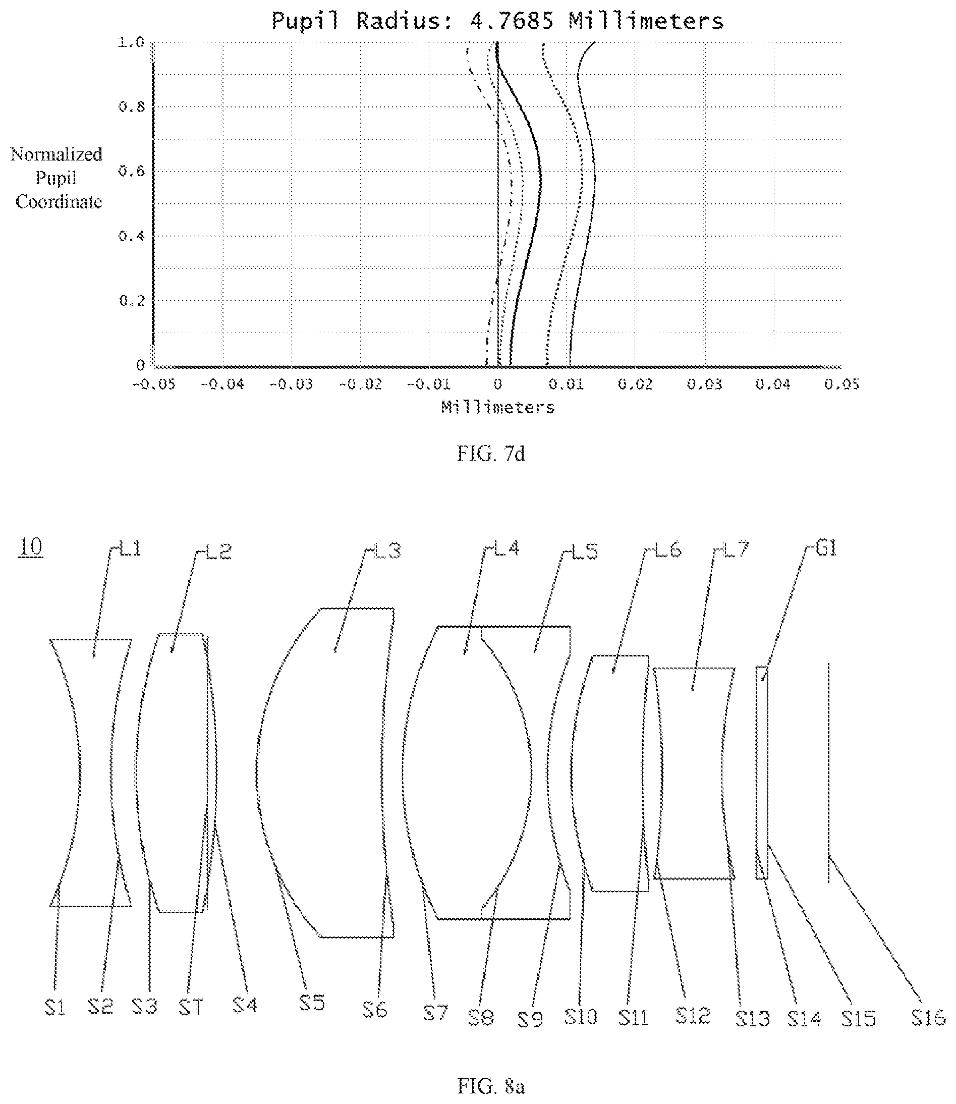
[0056] FIG. 7d is an axial chromatic aberration diagram of the optical lens system according to the seventh embodiment of the present disclosure.
[0057] FIG. 8a is a schematic cross-sectional view of the optical lens system according to an eighth embodiment of the present disclosure.
[0058] FIG. 8b is a field curvature diagram of the optical lens system according to the eighth embodiment of the present disclosure.
[0059] FIG. 8c is a distortion diagram of the optical lens system according to the eighth embodiment of the present disclosure.
[0060] FIG. 8d is an axial chromatic aberration diagram of the optical lens system according to the eighth embodiment of the present disclosure.
[0061] FIG. 9 is a schematic view of a vehicle camera according to an embodiment of the present disclosure.
REFERENCE NUMERALS OF MAIN COMPONENTS
TABLE-US-00001 [0062] first lens L1 second lens L2 third lens L3 fourth lens L4 fifth lens L5 sixth lens L6 seventh lens L7 filter G1 stop ST
[0063] The following embodiments will further illustrate the present disclosure with reference to the above drawings.
DETAILED DESCRIPTION OF PREFERRED EMBODIMENTS
[0064] In order to facilitate the understanding of the present disclosure, the present disclosure will be described more fully hereinafter with reference to the accompanying drawings. Several embodiments of the disclosure are presented in the drawings. However, the disclosure may be embodied in many different forms and is not limited to the embodiments described herein. Rather, these embodiments are provided so that this disclosure will be thorough and comprehensive.
[0065] Unless defined otherwise, all technical and scientific terms used herein have the same meaning as commonly understood by one of ordinary skill in the art to which this invention belongs. The terminology used herein in the description of the present invention is only for the purpose of describing specific embodiments, and is not intended to limit the present disclosure. The term "and/or" as used herein includes any and all combinations of one or more of the associated listed items.
Embodiment 1
[0066] Please refer to FIG. 1a, which is a structural diagram of an optical lens system 10 in a first embodiment of the present disclosure. From an object side to an imaging surface, the optical lens system 10 sequentially includes: a first lens L1 with a negative refractive power, a stop ST, a second lens L2 with a positive refractive power, a third lens L3 with a positive refractive power, a fourth lens L4 with a positive refractive power, a fifth lens L5 with a negative refractive power, a sixth lens L6 with a positive refractive power, a seventh lens L7 with a negative refractive power, and a filter G1. An object side surface S1 of the first lens L1 is a concave surface, the stop ST is positioned between an image side surface S2 of the first lens L1 and an object side surface S3 of the second lens L2. The object side surface S3 and an image side surface S4 of the second lens L2 both are convex surfaces. The third lens L3 includes an object side surface S5 and an image side surface S6, both are convex surfaces. The fourth lens S4 has an object side surface S7 which is convex, and the fifth lens L5 has an image side surface S9 which is concave. An object side surface S10 of the sixth lens L6 is convex, meanwhile an image side surface S11 of the sixth lens L6 is concave. Both of an object side surface S12 and an image side surface S13 of the seventh lens L7 are concave surfaces.
[0067] An image side surface of the fourth lens L4 is matched with and bonded to an object side surface of the fifth lens L5, in other words, the fifth lens L5 and the fourth lens L4 are bonded together to form a cemented lens, which is also called as an achromatic doublet lens.
[0068] The filter G1 includes an object side surface S14 and an image side surface S15, both of which are flat.
[0069] The first lens L1, the third lens L3, the fourth lens L4, the fifth lens L5 and the sixth lens L6 are glass spherical lenses, the second lens L2 and the seventh lens L7 are glass aspheric lenses.
[0070] The shapes of the aspherical surfaces of the optical lens system 10 satisfy the following equation:
z = ch 2 1 + 1 - ( 1 + K ) c 2 h 2 + Bh 4 + Ch 6 + Dh 8 + Eh 10 + Fh 12 , ##EQU00001##
[0071] Where z represents a vector height between a position on the surface and a vertex of the surface along an optical axis of the lens, c represents a curvature of the vertex of the surface, K is a quadratic surface coefficient, h is a distance between the position on the surface and the optical axis, B is a fourth order surface coefficient, C is a sixth order surface coefficient, D is an eighth order surface coefficient, E is a tenth order surface coefficient. F is a twelfth order surface coefficient.
[0072] It should be noted that the above-mentioned aspheric shape equation is not only applicable to the aspheric lenses of this embodiment, but also applicable to the aspheric lenses in the following embodiments of the present disclosure.
[0073] Further, the third lens L3 and the fourth lens L4 satisfy the following expression:
(dn/dt).sub.3+(dn/dt).sub.4<-2.times.10.sup.4/.degree. C.; [0074] where (dn/dt).sub.3 represents a temperature coefficient of refractive index of the third lens L3, (dn/dt).sub.4 represents a temperature coefficient of refractive index of the fourth lens L4.
[0075] It can be understood that, since the temperature coefficients of refractive index of the third lens L3 and the fourth lens L4 in the optical lens system 10 of the present disclosure are both negative values, the focal length of the optical lens system 10 can be increased at high temperature and decreased at low temperature, thereby effectively compensating the thermal expansion of the lens components, such as a lens barrel, a lens holder, and ensuring the optical lens system 10 has a good resolution at high and low temperatures.
[0076] Further, the third lens L3 and the fourth lens L4 satisfy the following expressions:
Vd.sub.3+Vd.sub.4>150;
.DELTA.Pg,F3+.DELTA.Pg,F4>0.005;
[0077] where Vd.sub.3 represents the abbe number of the third lens L3, Vd.sub.4 represents the abbe number of the fourth lens L4, .DELTA.Pg,F3 represents a deviation of relative partial dispersion from the abbe empirical formula of the third lens L3, .DELTA.Pg,F4 represents a deviation of relative partial dispersion from the abbe empirical formula of the fourth lens LA.
[0078] It can be understood that, the low dispersion and high relative partial dispersion of the third lens L3 and the fourth lens L4 of the optical lens system 10 in the present disclosure can effectively correct the secondary spectrum, reduce the difference in focus distance between different wavelengths of lights, and effectively improve the MTF value of different monochromatic lights in the visible light range, so that the lenses of the present disclosure have good effect on monochromatic lights of respective wavelength in the wide visible light range. It is beneficial to improve the resolution of the optical lens system 10 for objects that emit or reflect monochromatic lights of different wavelengths such as signal lights, highway signs, etc.
[0079] Further, the optical lens system 10 satisfies the following expressions:
0.5<.parallel.f.sub.52|-t.sub.52|<13;
0.1<.parallel.f.sub.61|-t.sub.61<10;
[0080] where f.sub.52 represents a focal length of an image side surface of the fifth lens L5, f.sub.61 represents a focal length of an object side surface of the sixth lens L6, t.sub.52 represents a distance from a vertex of an image side surface of the fifth lens L5 to the imaging surface of the optical lens system 10, t.sub.61 represents a distance from a vertex of an object side surface of the sixth lens L6 to the imaging surface of the optical lens system 10. Satisfying this condition can effectively eliminate the ghosting generated by the lenses, and avoid the ghosting of the lenses to interfere with the machine or human eyes recognition.
[0081] Further, the optical lens system 10 satisfies the following expression:
0.2<IH/.theta.<0.3:
[0082] where .theta. represents half field angle of the optical lens system 10, and IH represents an image height when the half field angle is 0. Satisfying this condition, the f-.theta. distortion of the optical lens system 10 can be well controlled, and the imaging deformation caused by the f-.theta. distortion can be effectively reduced.
[0083] Further, the third lens L3 and the fourth lens L4 satisfies the following expression:
40<.phi..sub.3+.phi..sub.4<75; [0084] where .phi..sub.3 represents a refractive power of the third lens L3, .phi..sub.4 represents a refractive power of the fourth lens L4.
[0085] Further, the third lens L3 and the fourth lens IA satisfies the following expression:
0.5<f.sub.1/r.sub.1<3;
[0086] where f.sub.1 represents a focal length of the first lens L1, r.sub.1 represents a radius of curvature of an object side surface of the first lens L1. When the value of f.sub.1/r.sub.1 exceeds an upper limit, it is not conducive to reduce the diameter of the lens; and when the value of f.sub.1/r.sub.1 exceeds a lower limit, it does not facilitate to process the lens.
[0087] Further, the optical lens system 10 satisfies the following expression:
5<CT.sub.2+CT.sub.3<13;
[0088] where CT.sub.2 represents a center thickness of the second lens L2, and CT.sub.3 represents a center thickness of the third lens L3. Satisfying this condition, it may be ensured that the optical lens system 10 can effectively reduce the field curvature and reduce the shift of the focus for lights in different fields of views.
[0089] Further, the optical lens system 10 satisfies the following expression:
1<f.sub.3/r.sub.5<4;
[0090] where f.sub.3 represents a focal length of the third lens L3, r.sub.5 represents a radius of curvature of an object side surface of the third lens L3. Satisfying this condition can ensure that the third lens L3 can converge the lights well, facilitate to reduce the rear lens diameter, thereby reducing the size of the lens.
[0091] Further, the optical lens system 10 satisfies the following expression:
-13<f.sub.7/r.sub.13<0,
[0092] where f.sub.7 represents a focal length of the seventh lens L7, and r.sub.13 represents a radius of the curvature of an image side surface of the seventh lens L7. Satisfying this condition can ensure that the optical lens system 10 can correct aberrations well, and can effectively control the exit angle of the lights. Beyond the range of this expression, it will increase the difficulty of lens processing and aberration correction.
[0093] In summary, the optical lens system 10 in the present disclosure provides the first lens L1 to the seventh lens L7, wherein the first lens L1 is configured for light collection and distortion correction, the second lens L2, the third lens L3, the fourth lens L4 and the sixth lens L6 are configured for converging the lights, the third lens L3 and the fourth lens L4 also can eliminate heat difference and secondary spectrum, the fifth lens L5 and the fourth lens L4 also can act as a negative lens and a positive lens to eliminate chromatic aberration, the difference between the abbe number Vd of the fourth lens L4 and the fifth lens L5 is greater than 30, the seventh lens L7 can eliminate aberrations and control the exit angle of the chief ray. Therefore, the optical lens system 10 has strong light passing ability; can adapt to the changes in brightness/darkness of the external environment, and also has a relatively high imaging clarity. In addition, by setting the lenses of the optical lens system 10 as glass lenses, the lens system can have better thermal stability performance. By properly distributing the refractive power, and enabling the third lens L3 and the fourth lens L4 to use materials with negative temperature index, low dispersion and high relative partial dispersion, the focus shift of the optical lens system 10 caused by changes in ambient temperature can be minimized, the problem of thermal drift can be solved, the secondary spectrum also can be corrected well, so that the focal positions of monochromatic lights of different wavelengths are closer. The lens of the present disclosure not only has reliable thermal stability, but also has good effect on monochromatic lights of each wavelength in a wide visible light range. It is beneficial to improve the resolution of the lens for the objects that emit or reflect monochromatic lights of different wavelengths such as signal indicators, highway signs, etc, so as to meet the requirements of the driverless vehicle system on the lens as much as possible.
[0094] Related parameters of each lens in the optical lens system 10 are shown in Table 1-1.
TABLE-US-00002 TABLE 1-1 Surface Radius of Refractive Abbe NO. Surface type curvature Thickness index number Object Subject Spherical surface Infinity Infinity surface S1 First lens Spherical surface -14.494478 2.371605 1.613 37.01 S2 Spherical surface -63.149885 0.261495 ST Stop Spherical surface Infinity 1.802385 S3 Second lens Aspheric surface 34.746436 4.103308 1.693 53.20 S4 Aspheric surface -74.219015 0.285721 S5 Third lens Spherical surface 18.289763 7.072520 1.497 81.59 S6 Spherical surface -18.289763 2.277053 S7 Fourth lens Spherical surface 18.581112 4.773657 1.593 67.33 S8 Fifth lens Spherical surface -11.880198 0.751239 1.689 31.16 S9 Spherical surface 11.880198 0.452731 S10 Sixth lens Spherical surface 12.035616 3.044081 1.911 35.26 S11 Spherical surface 40.715315 1.599017 S12 Seventh lens Aspheric surface -13.192815 0.802963 1.693 53.20 S13 Aspheric surface 50.505483 1.500000 S14 Filter Spherical surface Infinity 0.400000 1.517 64.20 S15 Spherical surface Infinity 2.027862 S16 The imaging Spherical surface Infinity -- surface
[0095] The parameters of the aspheric surfaces of the second lens L2 and the seventh lens L7 of this embodiment are shown in Table 1-2.
TABLE-US-00003 TABLE 1-2 Surface NO. K B C D E F S3 -1.670138 -8.022639E-05 -4.302874E-07 -1.085510E-08 7.123604E-11 0.000000E+00 S4 -8.862262 -2.201658E-05 -1.618435E-07 -8.234636E-09 9.767447E-11 0.000000E-00 S12 -5.956645 -8.492779E-04 5.495009E-05 -3.232166E-06 1.033001E-07 -1.285605E-09 S13 -16.121277 -3.339555E-04 3.810517E-05 -1.821911E-06 3.618848E-08 -6.152127E-11
[0096] FIG. 1b, FIG. 1c, and FIG. 1d illustrate the field curvature diagram, distortion diagram and axial chromatic aberration diagram of the optical lens system 10 in this embodiment, respectively. As can be seen from FIG. 1b to FIG. 1d, the field curvature, the distortion and the chromatic aberration can be well corrected in this embodiment.
Embodiment 2
[0097] Please refer to FIG. 2a, FIG. 2a is a structural diagram of an optical lens system 10 according to the second embodiment of the present disclosure. The lens structure provided in this embodiment is different from the lens structure in the first embodiment is that: (1) an object side surface and an image side surface of the first lens L1 both are concave surfaces, and an object side surface of the third lens L3 is a convex surface and an image side surface of the third lens L3 is a concave surface, and an object side surface of the seventh lens L7 is a convex surface and an image side surface of the seventh lens L7 is a concave surface; (2) the stop ST is disposed between the second lens L2 and the third lens L3; (3) the second lens L2 is a glass spherical lens; (4) the related parameters of other lenses are different. Related parameters of each lens are shown in Table 2-1.
TABLE-US-00004 TABLE 2-1 Surface Radius of Refractive Abbe NO. Surface type curvature Thickness index number Object Subject Spherical surface Infinity Infinity surface S1 First lens Spherical surface -11.592661 1.163199 1.613 37.01 S2 Spherical surface 19.751587 1.136888 S3 Second lens Spherical surface 22.924887 4.092293 1.723 38.02 S4 Spherical surface -17.734275 -0.968123 ST Stop Spherical surface Infinity 1.166996 S5 Third lens Spherical surface 12.082978 3.674930 1.437 95.10 S6 Spherical surface 33.642106 1.095780 S7 Fourth lens Spherical surface 14.100363 6.880603 1.593 67.33 S8 Fifth lens Spherical surface -9.400656 0.612328 1.689 31.16 S9 Spherical surface 16.477184 1.220307 S10 Sixth lens Spherical surface 19.128073 2.473526 1.911 35.26 S11 Spherical surface 35.740725 0.245258 S12 Seventh lens Aspheric surface 16.489875 5.975151 1.621 63.88 S13 Aspheric surface 12.098150 1.500000 S14 Filter Spherical surface Infinity 0.400000 1.517 64.20 S15 Spherical surface Infinity 2.240201 S16 The imaging Spherical surface Infinity -- surface
[0098] The parameters of the aspheric surfaces of the seventh lens L7 of this embodiment are shown in Table 2-2.
TABLE-US-00005 TABLE 2-2 Surface NO. K B C D E F S12 3.360248 -4.826164E-04 -8.875078E-06 2.124485E-07 -1.378097E-08 2.382802E-10 S13 0.960708 -6.283509E-05 -3.352469E-05 2.144107E-06 -9.533962E-08 1.698379E-09
[0099] FIG. 2b. FIG. 2c, and FIG. 2d illustrate the field curvature diagram, distortion diagram and axial chromatic aberration diagram of the optical lens system 10 in this embodiment, respectively. As can be seen from FIG. 2b to FIG. 2d, the field curvature, the distortion and the chromatic aberration can be well corrected in this embodiment.
Embodiment 3
[0100] Please refer to FIG. 3a, FIG. 3a is a structural diagram of an optical lens system 10 according to the third embodiment of the present disclosure. The lens structure provided in this embodiment is different from the lens structure in the first embodiment is that: (1) an object side surface and an image side surface of the first lens L1 both are concave surfaces, and an object side surface of the third lens L3 is a convex surface and an image side surface of the third lens L3 is a concave surface, and an object side surface of the seventh lens L7 is a convex surface and an image side surface of the seventh lens L7 is a concave surface; (2) the stop ST is disposed between the second lens L2 and the third lens L3; (3) the second lens L2 is a glass spherical lens and the sixth lens L6 is a glass aspherical lens; (4) the related parameters of other lenses are different. Related parameters of each lens are shown in Table 3-1.
TABLE-US-00006 TABLE 3-1 Surface Radius of Refractive Abbe NO. Surface type curvature Thickness index number Object Subject Spherical surface Infinity Infinity surface S1 First lens Spherical surface -11.976029 1.200553 1.613 37.01 S2 Spherical surface 18.442265 1.181351 S3 Second lens Spherical surface 21.411583 4.145002 1.723 38.02 S4 Spherical surface -19.286256 -0.877432 ST Stop Spherical surface Infinity 1.111799 S5 Third lens Spherical surface 11.252093 3.838694 1.437 95.10 S6 Spherical surface 29.187333 0.329973 S7 Fourth lens Spherical surface 14.256602 7.310105 1.593 67.33 S8 Fifth lens Spherical surface -9.549359 0.612328 1.689 31.16 S9 Spherical surface 18.539892 0.782115 S10 Sixth lens Aspheric surface 18.989284 2.670310 1.808 40.92 S11 Aspheric surface 39.330426 0.250289 S12 Seventh lens Aspheric surface 19.327695 5.989484 1.621 63.88 S13 Aspheric surface 12.028573 1.500000 S14 Filter Spherical surface Infinity 0.400000 1.517 64.20 S15 Spherical surface Infinity 2.224803 S16 The imaging Spherical surface Infinity -- surface
[0101] The parameters of the aspheric surfaces of the sixth lens L6 and the seventh lens L7 of this embodiment are shown in Table 3-2.
TABLE-US-00007 TABLE 3-2 Surface NO. K B C D E F S10 -0.227487 6.354141E-06 -5.605356E-06 5.589140E-07 -1.757158E-08 9.634393E-11 S11 4.159960 2.651268E-05 -6.080188E-07 2.382211E-06 -3.633551E-08 -7.768134E-10 S12 2.772528 -5.730588E-04 -1.564007E-06 2.851916E-06 -6.777178E-08 -1.419212E-10 S13 -0.788175 -1.570166E-04 -2.960847E-05 2.581358E-06 -1.101504E-07 1.724799E-09
[0102] FIG. 3b, FIG. 3c, and FIG. 3d illustrate the field curvature diagram, distortion diagram and axial chromatic aberration diagram of the optical lens system 10 in this embodiment, respectively. As can be seen from FIG. 3b to FIG. 3d, the field curvature, the distortion and the chromatic aberration can be well corrected in this embodiment.
Embodiment 4
[0103] Please refer to FIG. 4a, FIG. 4a is a structural diagram of an optical lens system 10 according to the fourth embodiment of the present disclosure. The lens structure provided in this embodiment is different from the lens structure in the first embodiment is that: (1) an object side surface and an image side surface of the first lens L1 both are concave surfaces; (2) the stop ST is disposed between the second lens L2 and the third lens L3; (3) the second lens L2 is a glass spherical lens and the third lens L3 is a glass aspherical lens; (4) the related parameters of other lenses are different. Related parameters of each lens are shown in Table 4-1.
TABLE-US-00008 TABLE 4-1 Surface Radius of Refractive Abbe NO. Surface type curvature Thickness index number Object Subject Spherical surface Infinity Infinity surface S1 First lens Spherical surface -12.919273 1.289841 1.613 37.01 S2 Spherical surface 23.733724 1.026969 S3 Second lens Spherical surface 21.252473 3.599612 1.723 38.02 S4 Spherical surface -32.121515 -0.345944 ST Stop Spherical surface Infinity 1.690004 S5 Third lens Aspheric surface 12.506290 7.143667 1.497 81.56 S6 Aspheric surface -52.754684 0.628636 S7 Fourth lens Spherical surface 16.042089 5.677139 1.593 67.33 S8 Fifth lens Spherical surface -10.081255 0.715993 1.689 31.16 S9 Spherical surface 11.246756 0.422645 S10 Sixth lens Spherical surface 10.742125 3.769487 1.911 35.26 S11 Spherical surface 25.024764 1.226018 S12 Seventh lens Aspheric surface -132.998530 2.250446 1.621 63.88 S13 Aspheric surface 18.349997 0.500000 S14 Filter Spherical surface Infinity 0.400000 1.517 64.20 S15 Spherical surface Infinity 2.506232 S16 The imaging Spherical surface Infinity -- surface
[0104] The parameters of the aspheric surfaces of the third lens L3 and the seventh lens L7 of this embodiment are shown in Table 4-2.
TABLE-US-00009 TABLE 4-2 Surface NO. K B C D E F S5 -0.129101 -2.872881E-05 -2.329265E-07 -1.880421E-09 -6.484697E-12 -9.658702E-13 S6 19.643388 4.654210E-05 -2.957472E-07 3.411484E-09 -2.612202E-10 1.231211E-12 S12 7.745911 -1.174336E-03 -6.115674E-06 1.103782E-06 -5.287868E-08 1.145548E-09 S13 5.080635 -8.256122E-04 -1.841075E-05 2.594343E-06 -1.282417E-07 2.386339E-09
[0105] FIG. 4b, FIG. 4c, and FIG. 4d illustrate the field curvature diagram, distortion diagram and axial chromatic aberration diagram of the optical lens system 10 in this embodiment, respectively. As can be seen from FIG. 4b to FIG. 4d, the field curvature, the distortion and the chromatic aberration can be well corrected in this embodiment.
Embodiment 5
[0106] Please refer to FIG. 5a, FIG. 5a is a structural diagram of an optical lens system 10 according to the fifth embodiment of the present disclosure. The lens structure provided in this embodiment is different from the lens structure in the first embodiment is that: (1) the second lens L2 is a glass spherical lens and the third lens L3 is a glass aspherical lens; (2) the related parameters of other lenses are different. Related parameters of each lens are shown in Table 5-1.
TABLE-US-00010 TABLE 5-1 Surface Radius of Refractive Abbe NO. Surface type curvature Thickness index number Object Subject Spherical surface Infinity Infinity surface S1 First lens Spherical surface -11.768684 1.294693 1.613 37.01 S2 Spherical surface -37.145784 0.116731 ST Stop Spherical surface Infinity 1.410072 S3 Second lens Spherical surface 71.865315 5.678253 1.702 41.14 S4 Spherical surface -71.865315 0.069331 S5 Third lens Aspheric surface 12.904154 6.238990 1.497 81.56 S6 Aspheric surface -21.680249 1.269446 S7 Fourth lens Spherical surface 18.280772 6.154973 1.593 67.33 S8 Fifth lens Spherical surface -11.781805 0.684010 1.689 31.16 S9 Spherical surface 11.781805 0.520732 S10 Sixth lens Spherical surface 11.864835 3.357487 1.911 35.26 S11 Spherical surface 38.183902 1.689353 S12 Seventh lens Aspheric surface -8.717423 0.792207 1.693 53.20 S13 Aspheric surface 36.697089 1.500000 S14 Filter Spherical surface Infinity 0.400000 1.517 64.20 S15 Spherical surface Infinity 1.236688 S16 The imaging Spherical surface Infinity -- surface
[0107] The parameters of the aspheric surfaces of the third lens L3 and the seventh lens L7 of this embodiment are show in Table 5-2.
TABLE-US-00011 TABLE 5-2 Surface NO. K B C D E F S5 -0.061775 -3.830596E-05 -2.344060E-07 -2.866294E-09 3.296568E-11 -1.876436E-12 S6 -3.550114 2.512564E-05 -6.496719E-07 1.316625E-08 -3.262862E-10 9.838649E-13 S12 -7.147404 8.951393E-04 -1.176606E-04 6.271543E-06 -2.267900E-07 3.924972E-09 S13 -30.074227 2.253746E-03 -1.522784E-04 7.617005E-06 -2.700699E-07 4.577218E-09
[0108] FIG. 5b, FIG. 5c, and FIG. 5d illustrate the field curvature diagram, distortion diagram and axial chromatic aberration diagram of the optical lens system 10 in this embodiment, respectively. As can be seen from FIG. 5b to FIG. 5d, the field curvature, the distortion and the chromatic aberration can be well corrected in this embodiment.
Embodiment 6
[0109] Please refer to FIG. 6a, FIG. 6a is a structural diagram of an optical lens system 10 according to the sixth embodiment of the present disclosure. The lens structure provided in this embodiment is different from the lens structure in the first embodiment is that: (1) an object side surface and an image side surface of the first lens L both are concave surfaces; (2) the related parameters of other lenses are different. Related parameters of each lens are shown in Table 6-1.
TABLE-US-00012 TABLE 6-1 Surface Radius of Refractive Abbe NO. Surface type curvature Thickness index number Object Subject Spherical surface Infinity Infinity surface S1 First lens Spherical surface -15.086739 3.764504 1.613 37.01 S2 Spherical surface 7511.960350 0.787493 ST Stop Spherical surface Infinity 0.568907 S3 Second lens Aspheric surface 17.873900 3.581276 1.693 53.20 S4 Aspheric surface -66.254643 3.795931 S5 Third lens Spherical surface 18.922684 5.073042 1.497 81.59 S6 Spherical surface -22.380420 0.200884 S7 Fourth lens Spherical surface 18.637740 4.801748 1.593 67.33 S8 Fifth lens Spherical surface -13.216421 0.698164 1.689 31.16 S9 Spherical surface 13.192973 0.780003 S10 Sixth lens Spherical surface 17.076361 2.643280 1.911 35.26 S11 Spherical surface 102.025137 1.768678 S12 Seventh lens Aspheric surface -10.694324 0.882926 1.693 53.70 S13 Aspheric surface 148.880149 1.500000 S14 Filter Spherical surface Infinity 0.400000 1.517 64.20 S15 Spherical surface Infinity 1.427990 S16 The imaging Spherical surface Infinity -- surface
[0110] The parameters of the aspheric surfaces of the second lens L2 and the seventh lens L7 of this embodiment are shown in Table 6-2.
TABLE-US-00013 TABLE 6-2 Surface NO. K B C D E F S3 -1.024586 -4.179503E-06 1.235109E-06 -4.097853E-08 9.340466E-10 -7.726421E-12 S4 -20.001137 4.736774E-05 1.384022E-06 -4.010289E-08 8.986167E-10 -6.938365E-12 S12 -0.887615 2.034939E-05 6.852168E-06 -9.632577E-07 3.693775E-08 5.187990E-10 S13 -10.065135 1.915262E-04 -2.803897E-06 5.087626E-08 -8.218600E-09 2.166400E-10
[0111] FIG. 6b, FIG. 6c, and FIG. 6d illustrate the field curvature diagram, distortion diagram and axial chromatic aberration diagram of the optical lens system 10 in this embodiment, respectively. As can be seen from FIG. 6b to FIG. 6d, the field curvature, the distortion and the chromatic aberration can be well corrected in this embodiment.
Embodiment 7
[0112] Please refer to FIG. 7a, FIG. 7a is a structural diagram of an optical lens system 10 according to the seventh embodiment of the present disclosure. The lens structure provided in this embodiment is different from the lens structure in the first embodiment is that: (1) the object side surface and image side surface of the first lens L1 both are concave surfaces and an object side surface of the seventh lens L7 is a convex surface and an image side surface of the seventh lens L7 is a concave surface; (2) the stop ST is disposed between the second lens L2 and the third lens L3; (3) the second lens L2 is a glass spherical lens; (4) the related parameters of other lenses are different. Related parameters of each lens are shown in Table 7-1.
TABLE-US-00014 TABLE 7-1 Surface Radius of Refractive Abbe NO. Surface type curvature Thickness index number Object Subject Spherical surface Infinity Infinity surface S1 First lens Spherical surface -11.869604 1.184962 1.689 31.16 S2 Spherical surface 56.436099 0.465043 S3 Second lens Spherical surface 40.362307 1.799362 1.923 20.88 S4 Spherical surface -67.992181 -0.031767 ST Stop Spherical surface Infinity 0.231758 S5 Third lens Spherical surface 13.935701 4.004251 1.678 55.56 S6 Spherical surface -36.567965 0.199991 S7 Fourth lens Spherical surface 14.176259 4.595935 1.593 67.33 S8 Fifth lens Spherical surface -13.594701 0.699995 1.741 27.76 S9 Spherical surface 10.740992 2.295061 S10 Sixth lens Spherical surface 8.816665 3.190814 1.901 37.05 S11 Spherical surface 14.360952 0.919291 S12 Seventh lens Aspheric surface 17.133016 3.891408 1.693 53.20 S13 Aspheric surface 11.144885 1.500000 S14 Filter Spherical surface Infinity 0.400000 1.517 64.20 S15 Spherical surface Infinity 2.508511 S16 The imaging Spherical surface Infinity -- surface
[0113] The parameters of the aspheric surfaces of the seventh lens L7 of this embodiment are shown in Table 7-2.
TABLE-US-00015 TABLE 7-2 Surface NO. K B C D E F S12 7.379160 -1.027395E-03 -1.532344E-05 2.720411E-07 -3.319238E-09 0.000000E+00 S13 3.470672 -6.495477E-04 -2.818808E-05 1.283836E-06 -3.869590E-08 0.000000E+00
[0114] FIG. 7b, FIG. 7c, and FIG. 7d illustrate the field curvature diagram, distortion diagram and axial chromatic aberration diagram of the optical lens system 10 in this embodiment, respectively. As can be seen from FIG. 7b to FIG. 7d, the field curvature, the distortion and the chromatic aberration can be well corrected in this embodiment.
Embodiment 8
[0115] Please refer to FIG. 8a, FIG. 8a is a structural diagram of an optical lens system 10 according to the eighth embodiment of the present disclosure. The lens structure provided in this embodiment is different from the lens structure in the first embodiment is that: (1) the object side surface and image side surface of the first lens L1 both are concave surfaces and an object side surface of the third lens L3 is a convex surface and an image side surface of the third lens L3 is a concave surface and an object side surface of the seventh lens L7 is a convex surface and an image side surface of the seventh lens L7 is a concave surface; (2) the stop ST is disposed between the second lens L2 and the third lens L3; (3) the second lens L2 is a glass spherical lens and the third lens L3 is a glass aspherical lens; (4) the related parameters of other lenses are different. Related parameters of each lens are shown in Table 8-1.
TABLE-US-00016 TABLE 8-1 Surface Radius of Refractive Abbe NO. Surface type curvature Thickness index number Subject Spherical surface Infinity Infinity S1 First lens Spherical surface -13.728598 1.348103 1.613 37.01 S2 Spherical surface 19.460816 1.115384 S3 Second lens Spherical surface 19.434470 3.453031 1.723 38.02 S4 Spherical surface -31.003429 -0.390284 ST Stop Spherical surface Infinity 2.149615 S5 Thirds Aspheric surface 10.793669 5.466395 1.497 81.59 S6 Aspheric surface 113.187699 0.880028 S7 Fourth lens Spherical surface 13.996411 5.585765 1.593 67.33 S8 Fifth lens Spherical surface -9.196558 0.699455 1.689 31.16 S9 Spherical surface 13.686747 1.027338 S10 Sixth lens Spherical surface 13.866547 3.119939 1.911 35.26 S11 Spherical surface 43.336727 0.830557 S12 Seventh lens Aspheric surface 53.858264 2.592158 1.621 63.88 S13 Aspheric surface 11.742482 1.500000 S14 Filter Spherical surface Infinity 0.400000 1.517 64.20 S15 Spherical surface Infinity 2.263113 S16 The imaging Spherical surface Infinity -- surface
[0116] The parameters of the aspheric surfaces of the third lens L3 and the seventh lens L7 of this embodiment are shown in Table 8-2.
TABLE-US-00017 TABLE 8-2 Surface NO. K B C D E F S5 -0.038258 -1.585391E-06 9.106299E-07 -1.604129E-08 2.777369E-10 -6.838692E-13 S6 226.067288 5.993153E-05 2.791742E-06 -9.818705E-08 2.300783E-09 -1.980628E-11 S12 43.893821 -1.107150E-03 -1.971119E-05 1.654027E-06 -7.941819E-08 1.386705E-09 S13 1.207905 -7.848638E-04 -3.034763E-05 2.708641E-06 -1.185474E-07 1.968214E-09
[0117] FIG. 8b, FIG. 8c, and FIG. 8d illustrate the field curvature diagram, distortion diagram and axial chromatic aberration diagram of the optical lens system 10 in this embodiment, respectively. As can be seen from FIG. 8b to FIG. 8d, the field curvature, the distortion and the chromatic aberration can be well corrected in this embodiment.
[0118] Table 9 shows the above eight embodiments and their corresponding optical characteristics. Table 9 includes the system focal length f, the aperture number F # and the system optical total length TTL, and values corresponding to each of the preceding conditional expressions.
TABLE-US-00018 TABLE 9 Embodi- Embodi- Embodi- Embodi- Embodi- Embodi- Embodi- Embodi- Condition ment 1 ment 2 ment 3 ment 4 ment 5 ment 6 ment 7 ment 8 f (mm) 15.488 15.406 15.430 15.430 15.362 15.481 15.259 15.314 F# 1.600 1.600 1.600 1.600 1.600 1.600 1.600 1.600 TTL (mm) 33.5 33.4 33.2 33.5 33.3 33.5 28.3 32.5 .phi..sub.3 + .phi..sub.4 60.287 70.617 69.151 55.924 56.798 61.073 46.333 53.408 (dn/dt).sub.3 + (dn/dt).sub.4 -8.1 .times. 10.sup.-6 -8.3 .times. 10.sup.-6 -8.8 .times. 10.sup.-6 -7.5 .times. 10.sup.-6 -8.1 .times. 10.sup.-6 -9.0 .times. 10.sup.-6 -2.1 .times. 10.sup.-6 -7.5 .times. 10.sup.-6 Vd.sub.3 + Vd.sub.4 180.082 193.588 193.588 180.047 180.047 180.096 150.648 180.047 .DELTA.Pg, F3 + .DELTA.Pg, F4 0.040 0.068 0.068 0.048 0.048 0.049 0.009 0.048 ||f.sub.52|-t.sub.52| 7.331 9.239 12.455 4.202 6.617 8.836 0.690 7.531 ||f.sub.61|-t.sub.61| 3.782 7.570 9.863 0.124 3.091 9.227 3.064 3.948 IH/.theta. 0.270 0.269 0.271 0.270 0.269 0.270 0.271 0.271 f.sub.1/r.sub.1 2.148 1.009 0.970 1.038 2.425 1.621 1.185 0.938 CT.sub.2 + CT.sub.3 11.176 7.767 7.984 10.743 11.917 8.654 5.804 8.919 f.sub.3/r.sub.5 1.073 3.389 3.490 1.684 1.339 1.134 1.100 2.181 f.sub.7/r.sub.13 -0.296 -12.619 -6.209 -1.404 -0.453 -0.096 -5.608 -2.104
[0119] In the above embodiments, the optical system lens provided by the present disclosure can achieve the following optical index: (1) optical total length: TTL<33.5 mm, (2) applicable spectral range: 400 nm.about.700 nm.
[0120] As illustrated in FIG. 9, the present disclosure provides a vehicle camera 100 mounted in a vehicle 20. The vehicle camera 100 includes an image sensor 101 and the optical lens system 10 of any embodiment as described above. The image sensor 101 is used to convert an optical image formed by the optical lens system 10 into electric signals, so that a driverless vehicle system of the vehicle 20 can control the direction or the speed of the vehicle 20 according to the electric signals to implement the functions of driverless driving.
[0121] The above-mentioned embodiments are merely illustrative of several embodiments of the present disclosure, and the description thereof is more specific and detailed, however is not to be construed as limiting the scope of the disclosure. It should be noted that various variations and modifications may be made by those skilled in the art without departing from the spirit and scope of the disclosure. Therefore, the scope of the disclosure should be determined by the appended claims.
* * * * *
D00000
D00001
D00002
D00003
D00004
D00005
D00006
D00007
D00008
D00009
D00010
D00011
D00012


XML
uspto.report is an independent third-party trademark research tool that is not affiliated, endorsed, or sponsored by the United States Patent and Trademark Office (USPTO) or any other governmental organization. The information provided by uspto.report is based on publicly available data at the time of writing and is intended for informational purposes only.
While we strive to provide accurate and up-to-date information, we do not guarantee the accuracy, completeness, reliability, or suitability of the information displayed on this site. The use of this site is at your own risk. Any reliance you place on such information is therefore strictly at your own risk.
All official trademark data, including owner information, should be verified by visiting the official USPTO website at www.uspto.gov. This site is not intended to replace professional legal advice and should not be used as a substitute for consulting with a legal professional who is knowledgeable about trademark law.